WO2017115538A1 - Article absorbant - Google Patents
Article absorbant Download PDFInfo
- Publication number
- WO2017115538A1 WO2017115538A1 PCT/JP2016/080991 JP2016080991W WO2017115538A1 WO 2017115538 A1 WO2017115538 A1 WO 2017115538A1 JP 2016080991 W JP2016080991 W JP 2016080991W WO 2017115538 A1 WO2017115538 A1 WO 2017115538A1
- Authority
- WO
- WIPO (PCT)
- Prior art keywords
- joint
- joint portion
- absorbent article
- diaper
- lateral direction
- Prior art date
- Legal status (The legal status is an assumption and is not a legal conclusion. Google has not performed a legal analysis and makes no representation as to the accuracy of the status listed.)
- Ceased
Links
Images




Classifications
-
- A—HUMAN NECESSITIES
- A61—MEDICAL OR VETERINARY SCIENCE; HYGIENE
- A61F—FILTERS IMPLANTABLE INTO BLOOD VESSELS; PROSTHESES; DEVICES PROVIDING PATENCY TO, OR PREVENTING COLLAPSING OF, TUBULAR STRUCTURES OF THE BODY, e.g. STENTS; ORTHOPAEDIC, NURSING OR CONTRACEPTIVE DEVICES; FOMENTATION; TREATMENT OR PROTECTION OF EYES OR EARS; BANDAGES, DRESSINGS OR ABSORBENT PADS; FIRST-AID KITS
- A61F13/00—Bandages or dressings; Absorbent pads
- A61F13/15—Absorbent pads, e.g. sanitary towels, swabs or tampons for external or internal application to the body; Supporting or fastening means therefor; Tampon applicators
- A61F13/45—Absorbent pads, e.g. sanitary towels, swabs or tampons for external or internal application to the body; Supporting or fastening means therefor; Tampon applicators characterised by the shape
- A61F13/49—Absorbent pads, e.g. sanitary towels, swabs or tampons for external or internal application to the body; Supporting or fastening means therefor; Tampon applicators characterised by the shape specially adapted to be worn around the waist, e.g. diapers, nappies
- A61F13/496—Absorbent pads, e.g. sanitary towels, swabs or tampons for external or internal application to the body; Supporting or fastening means therefor; Tampon applicators characterised by the shape specially adapted to be worn around the waist, e.g. diapers, nappies in the form of pants or briefs
- A61F13/4963—Absorbent pads, e.g. sanitary towels, swabs or tampons for external or internal application to the body; Supporting or fastening means therefor; Tampon applicators characterised by the shape specially adapted to be worn around the waist, e.g. diapers, nappies in the form of pants or briefs characterized by the seam
-
- A—HUMAN NECESSITIES
- A61—MEDICAL OR VETERINARY SCIENCE; HYGIENE
- A61F—FILTERS IMPLANTABLE INTO BLOOD VESSELS; PROSTHESES; DEVICES PROVIDING PATENCY TO, OR PREVENTING COLLAPSING OF, TUBULAR STRUCTURES OF THE BODY, e.g. STENTS; ORTHOPAEDIC, NURSING OR CONTRACEPTIVE DEVICES; FOMENTATION; TREATMENT OR PROTECTION OF EYES OR EARS; BANDAGES, DRESSINGS OR ABSORBENT PADS; FIRST-AID KITS
- A61F13/00—Bandages or dressings; Absorbent pads
- A61F13/15—Absorbent pads, e.g. sanitary towels, swabs or tampons for external or internal application to the body; Supporting or fastening means therefor; Tampon applicators
- A61F13/45—Absorbent pads, e.g. sanitary towels, swabs or tampons for external or internal application to the body; Supporting or fastening means therefor; Tampon applicators characterised by the shape
- A61F13/49—Absorbent pads, e.g. sanitary towels, swabs or tampons for external or internal application to the body; Supporting or fastening means therefor; Tampon applicators characterised by the shape specially adapted to be worn around the waist, e.g. diapers, nappies
- A61F13/49007—Form-fitting, self-adjusting disposable diapers
- A61F13/49009—Form-fitting, self-adjusting disposable diapers with elastic means
- A61F13/49011—Form-fitting, self-adjusting disposable diapers with elastic means the elastic means is located at the waist region
-
- A—HUMAN NECESSITIES
- A61—MEDICAL OR VETERINARY SCIENCE; HYGIENE
- A61F—FILTERS IMPLANTABLE INTO BLOOD VESSELS; PROSTHESES; DEVICES PROVIDING PATENCY TO, OR PREVENTING COLLAPSING OF, TUBULAR STRUCTURES OF THE BODY, e.g. STENTS; ORTHOPAEDIC, NURSING OR CONTRACEPTIVE DEVICES; FOMENTATION; TREATMENT OR PROTECTION OF EYES OR EARS; BANDAGES, DRESSINGS OR ABSORBENT PADS; FIRST-AID KITS
- A61F13/00—Bandages or dressings; Absorbent pads
- A61F13/15—Absorbent pads, e.g. sanitary towels, swabs or tampons for external or internal application to the body; Supporting or fastening means therefor; Tampon applicators
- A61F13/45—Absorbent pads, e.g. sanitary towels, swabs or tampons for external or internal application to the body; Supporting or fastening means therefor; Tampon applicators characterised by the shape
- A61F13/49—Absorbent pads, e.g. sanitary towels, swabs or tampons for external or internal application to the body; Supporting or fastening means therefor; Tampon applicators characterised by the shape specially adapted to be worn around the waist, e.g. diapers, nappies
- A61F13/49058—Absorbent pads, e.g. sanitary towels, swabs or tampons for external or internal application to the body; Supporting or fastening means therefor; Tampon applicators characterised by the shape specially adapted to be worn around the waist, e.g. diapers, nappies characterised by the modular concept of constructing the diaper
- A61F13/4906—Absorbent pads, e.g. sanitary towels, swabs or tampons for external or internal application to the body; Supporting or fastening means therefor; Tampon applicators characterised by the shape specially adapted to be worn around the waist, e.g. diapers, nappies characterised by the modular concept of constructing the diaper the diaper having an outer chassis forming the diaper and an independent absorbent structure attached to the chassis
- A61F13/49061—Absorbent pads, e.g. sanitary towels, swabs or tampons for external or internal application to the body; Supporting or fastening means therefor; Tampon applicators characterised by the shape specially adapted to be worn around the waist, e.g. diapers, nappies characterised by the modular concept of constructing the diaper the diaper having an outer chassis forming the diaper and an independent absorbent structure attached to the chassis the diaper having one or two waist members forming the diaper waist region and an independent absorbent structure attached to the one or two waist members forming the crotch region
-
- A—HUMAN NECESSITIES
- A61—MEDICAL OR VETERINARY SCIENCE; HYGIENE
- A61F—FILTERS IMPLANTABLE INTO BLOOD VESSELS; PROSTHESES; DEVICES PROVIDING PATENCY TO, OR PREVENTING COLLAPSING OF, TUBULAR STRUCTURES OF THE BODY, e.g. STENTS; ORTHOPAEDIC, NURSING OR CONTRACEPTIVE DEVICES; FOMENTATION; TREATMENT OR PROTECTION OF EYES OR EARS; BANDAGES, DRESSINGS OR ABSORBENT PADS; FIRST-AID KITS
- A61F13/00—Bandages or dressings; Absorbent pads
- A61F13/15—Absorbent pads, e.g. sanitary towels, swabs or tampons for external or internal application to the body; Supporting or fastening means therefor; Tampon applicators
- A61F13/45—Absorbent pads, e.g. sanitary towels, swabs or tampons for external or internal application to the body; Supporting or fastening means therefor; Tampon applicators characterised by the shape
- A61F13/49—Absorbent pads, e.g. sanitary towels, swabs or tampons for external or internal application to the body; Supporting or fastening means therefor; Tampon applicators characterised by the shape specially adapted to be worn around the waist, e.g. diapers, nappies
- A61F13/496—Absorbent pads, e.g. sanitary towels, swabs or tampons for external or internal application to the body; Supporting or fastening means therefor; Tampon applicators characterised by the shape specially adapted to be worn around the waist, e.g. diapers, nappies in the form of pants or briefs
-
- A—HUMAN NECESSITIES
- A61—MEDICAL OR VETERINARY SCIENCE; HYGIENE
- A61F—FILTERS IMPLANTABLE INTO BLOOD VESSELS; PROSTHESES; DEVICES PROVIDING PATENCY TO, OR PREVENTING COLLAPSING OF, TUBULAR STRUCTURES OF THE BODY, e.g. STENTS; ORTHOPAEDIC, NURSING OR CONTRACEPTIVE DEVICES; FOMENTATION; TREATMENT OR PROTECTION OF EYES OR EARS; BANDAGES, DRESSINGS OR ABSORBENT PADS; FIRST-AID KITS
- A61F13/00—Bandages or dressings; Absorbent pads
- A61F13/15—Absorbent pads, e.g. sanitary towels, swabs or tampons for external or internal application to the body; Supporting or fastening means therefor; Tampon applicators
- A61F13/56—Supporting or fastening means
-
- A—HUMAN NECESSITIES
- A61—MEDICAL OR VETERINARY SCIENCE; HYGIENE
- A61F—FILTERS IMPLANTABLE INTO BLOOD VESSELS; PROSTHESES; DEVICES PROVIDING PATENCY TO, OR PREVENTING COLLAPSING OF, TUBULAR STRUCTURES OF THE BODY, e.g. STENTS; ORTHOPAEDIC, NURSING OR CONTRACEPTIVE DEVICES; FOMENTATION; TREATMENT OR PROTECTION OF EYES OR EARS; BANDAGES, DRESSINGS OR ABSORBENT PADS; FIRST-AID KITS
- A61F13/00—Bandages or dressings; Absorbent pads
- A61F13/15—Absorbent pads, e.g. sanitary towels, swabs or tampons for external or internal application to the body; Supporting or fastening means therefor; Tampon applicators
- A61F13/56—Supporting or fastening means
- A61F13/5622—Supporting or fastening means specially adapted for diapers or the like
- A61F13/5633—Supporting or fastening means specially adapted for diapers or the like open type diaper
- A61F13/5638—Supporting or fastening means specially adapted for diapers or the like open type diaper adjustable open type diapers
-
- A—HUMAN NECESSITIES
- A61—MEDICAL OR VETERINARY SCIENCE; HYGIENE
- A61F—FILTERS IMPLANTABLE INTO BLOOD VESSELS; PROSTHESES; DEVICES PROVIDING PATENCY TO, OR PREVENTING COLLAPSING OF, TUBULAR STRUCTURES OF THE BODY, e.g. STENTS; ORTHOPAEDIC, NURSING OR CONTRACEPTIVE DEVICES; FOMENTATION; TREATMENT OR PROTECTION OF EYES OR EARS; BANDAGES, DRESSINGS OR ABSORBENT PADS; FIRST-AID KITS
- A61F13/00—Bandages or dressings; Absorbent pads
- A61F13/15—Absorbent pads, e.g. sanitary towels, swabs or tampons for external or internal application to the body; Supporting or fastening means therefor; Tampon applicators
- A61F13/56—Supporting or fastening means
- A61F13/5622—Supporting or fastening means specially adapted for diapers or the like
- A61F13/565—Supporting or fastening means specially adapted for diapers or the like pants type diaper
Definitions
- the present invention relates to an absorbent article.
- the joint strength of the joint portion is set so that the joint portion of the front and rear waist portions can be easily peeled off at the time of replacement. It is assumed that the joint portion between the waist portion and the locking member is set to the same joint strength. If it does so, when a locking member is pulled at the time of wearing of a diaper, there is a possibility that a joined part of a back waist part and a locking member may be damaged.
- the present invention has been made in view of the above problems, and in an open pants-type diaper, an absorbent article that is less likely to be damaged on the open side when worn and that is easily peeled off on the opposite side from the open side when replaced.
- the purpose is to provide.
- a main invention for achieving the above object has a longitudinal direction, a transverse direction intersecting with the longitudinal direction, and a longitudinal direction intersecting with the longitudinal direction and the transverse direction, and the front along the transverse direction.
- An absorbent article comprising: a waistline portion; a rear waistline portion along the lateral direction; and a crotch portion provided between the front waistline portion and the rear waistline portion, wherein the absorbent article in the lateral direction
- An end portion on one side of the rear waistline portion and an end portion on one side of the front waistline portion in the lateral direction are joined by a first joint portion, and on the other side of the rear waistline portion in the lateral direction.
- the end portion is joined by a second joining portion and a retaining member having a retaining portion that can be secured to the front waistline portion when worn, and the joining strength of the second joining portion is that of the first joining portion. It is an absorbent article characterized by being larger than the bonding strength.
- the present invention it is possible to provide an absorbent article in which the open side is less likely to be damaged when worn, and the open side and the opposite side are easily peeled off at the time of replacement.
- FIG. 4A is a schematic cross-sectional view of the front waistline portion
- FIG. 4B is a schematic cross-sectional view of the back waistline portion
- FIG. 4C is a schematic cross-sectional view of the locking member.
- FIG. 5A shows a first joint in Example 1
- FIG. 5B shows a second joint in Example 2.
- FIG. 6A shows a first joint in the second embodiment
- FIG. 6B shows a second joint in the second embodiment.
- FIG. 7A to FIG. 7C are diagrams showing a second joint portion in the third embodiment.
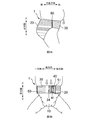
- FIG. 9A is a view of a diaper in a worn state as viewed from the side
- FIG. 9B is a view of the diaper in a worn state as viewed from the front
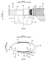
- FIG. 10A is a schematic plan view showing an example of the position of the locking portion when worn
- FIG. 10B is a schematic view when the diaper in the state of FIG. 10A is viewed from above.
- An absorbent article comprising a waistline portion, and a crotch portion provided between the front waistline portion and the rear waistline portion, and an end portion on one side of the rear waistline portion in the lateral direction;
- the one end portion of the front waistline portion in the lateral direction is joined by a first joint portion, and the other end portion of the rear waistline portion in the lateral direction is connected to the front waistline portion when worn.
- Absorption characterized in that it is joined by a latching member having a latchable latching part and a second joint part, and the joint strength of the second joint part is greater than the joint strength of the first joint part. Sex goods. According to such an absorbent article, even if the locking member is pulled when the diaper is worn, the second joint portion (open side) is not easily damaged, and when the diaper is replaced, the first joint portion (open side and The opposite side) can be easily peeled off, and the diaper 1 can be easily replaced.
- each of the first joint and the second joint has a plurality of welding regions, and a plurality of the second joints out of the total area of the second joints.
- the ratio of the area which the said welding area occupies is larger than the ratio of the area which the said several welding area of the said 1st junction part occupies among the area of the whole area
- the absorbent article characterized by the above-mentioned.
- the joint strength of the second joint portion can be made larger than the joint strength of the first joint portion.
- Such an absorbent article wherein a pattern of the plurality of welded areas in the first joint portion is different from a pattern of the plurality of welded areas in the second joint portion.
- the ratio of the area occupied by the welding region in the area of the entire region of the second joint portion is set to a plurality of the first joint portion in the area of the entire region of the first joint portion. It can be made larger than the ratio of the area occupied by the welding region.
- the weld region of the second joint portion has an inner end in the horizontal direction having a predetermined length along the vertical direction. According to such an absorbent article, even when the locking member is pulled in the lateral direction when the absorbent article is worn, and a force acts on the laterally inner end of the welding region of the second joint portion, the end Is unlikely to be the starting point for tears. Therefore, it is possible to make the second joint portion more difficult to break.
- the weld region of the first joint portion has the shortest length in the lateral direction in at least one of the upper end portion and the lower end portion in the longitudinal direction. Goods. According to such an absorbent article, the strength of the upper end and the lower end of the welded region of the first joint is the weakest. Therefore, when a force in the vertical direction is applied to break the first joint portion during replacement of the absorbent article, the upper end portion and the lower end portion of the welding region become the starting point of peeling. Therefore, the first joint portion can be more easily peeled off.
- the end of the locking portion on the side of the second joint portion is located at the end of the crotch portion on the side opposite to the first joint portion. Furthermore, in the state which latched the said latching
- the absorbent article characterized by the above-mentioned. According to such an absorbent article, since the rear waistline portion and the locking member are joined and the second rigid joint portion is located in front of the wearer (abdomen), the wearer's stomach protrudes. A downward displacement of the absorbent article (front waistline portion) can be suppressed.
- Such an absorbent article is characterized in that the rigidity at the second joint portion is greater than the rigidity at the front waistline portion. According to such an absorbent article, the support for the downward displacement of the front waistline portion is more reliable, and the downward displacement of the absorbent article (front waistline portion) due to the protrusion of the wearer's stomach is further suppressed. Is done.
- the number of members overlapping in the second joint portion is greater than the number of members overlapping in the front waistline portion.
- the rigidity in the second joint portion can be made larger than the rigidity in the front waistline portion.
- FIG. 1 is a perspective image view of a single-open pants-type disposable diaper 1 (hereinafter referred to as a diaper).
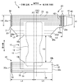
- FIG. 2 is a plan view of the diaper 1 in the unfolded state. In addition, it is a figure of the state which extended the elastic member which the diaper 1 has to such an extent that the wrinkles of the diaper 1 disappear.
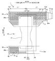
- FIG. 3 is a diagram illustrating the elastic regions X and Y.
- FIG. 4A is a schematic cross-sectional view of the front waistline portion 30,
- FIG. 4B is a schematic cross-sectional view of the back waistline portion 20, and
- FIG. 4C is a schematic cross-sectional view of the locking member 40.
- the diaper 1 has a “longitudinal direction”, a “lateral direction” that intersects the longitudinal direction, and a “front-rear direction” that intersects the longitudinal direction and the lateral direction, and is disposed in the crotch of the wearer to absorb excrement.
- the “absorbent body 10 (inseam)”, the “rear waistline portion 20” covering the back side of the wearer, the “front waistline portion 30” covering the abdomen side of the wearer, and the lateral direction of the rear waistline portion 20 It has a “locking member 40” protruding outward in the lateral direction from the other end.
- the center line RC indicates the center of the rear waistline portion 20 in the lateral direction
- the center line BC indicates a position that is substantially the center of the wearer's body with one leg put in
- the center line AC Indicates the lateral center of the absorbent body 10.
- the center line RC is the same position as the center line BC, and the center lines RC and BC are the other side (right side) in the lateral direction from the center line AC.
- the unfolded state in FIG. 2 is that the first joint 50 and the second joint 51 in FIG. 1 are separated and opened, and the locking member 40 is removed from the front waistline 30 to unfold the entire diaper 1 in a plane. It is in the state. 2, the rear waistline portion 20 and the front waistline portion 30 are disposed such that the longitudinal direction thereof is along the lateral direction of the diaper 1 and is spaced apart in the longitudinal direction. Between these, the absorptive main body 10 (crotch part) is provided so that the longitudinal direction may follow the longitudinal direction of the diaper 1.
- back waistline part 20 is being fixed to the skin side surface of the longitudinal direction one end part of the absorptive main body 10
- front waistline part 30 is being fixed to the skin side surface of the longitudinal direction other end part of the absorptive main body 10.
- the diaper 1 in the unfolded state in FIG. 2 is folded in half at the approximate center in the vertical direction, and the rear waistline portion 20 and the front waistline portion 30 are joined at the first joint portion 50 at the end of one side in the horizontal direction of the diaper 1.
- the leg opening HL1 on one side is formed.
- the rear waistline portion 20 and the front waistline portion 30 are not joined at the end portion on the other side in the lateral direction of the diaper 1, but the end portion on the other side in the lateral direction of the rear waistline portion 20 and the locking member 40 are second. Joined at the joint 51.
- the locking member 40 is locked to the front waistline portion 30, the other leg periphery opening HL2 and the waistline opening HB are formed.
- the absorptive main body 10 (crotch part) has a rectangular shape in plan view, and absorbs and holds liquid 11 and a liquid-permeable surface sheet 12 (for example, nonwoven fabric) that covers the absorbent body 11 from the skin side of the wearer.
- the liquid-impermeable back sheet 13 (for example, a polyethylene film, a polypropylene film, etc.) which covers the absorber 11 from the non-skin side.
- the absorbent body 11 is formed by molding liquid absorbent fibers such as pulp fibers into a predetermined shape such as an hourglass shape, and a superabsorbent polymer is mixed therein.
- the absorbent main body 10 may be provided with a three-dimensional gather portion that prevents side leakage and a leg gather portion that improves the fit around the legs.
- the back waistline part 20 is a planar view shape combining a rectangle and a substantially trapezoid, and is a skin side sheet 21 (for example, a soft sheet such as a nonwoven fabric) located on the skin side of the wearer and a non-skin side located on the non-skin side.
- a sheet 22 (for example, a soft sheet such as a nonwoven fabric) and a plurality of thread rubbers 23 positioned between the skin side sheet 21 and the non-skin side sheet 22 are provided.
- the vertical upper end of the non-skin side sheet 22 is folded back toward the skin so as to cover the upper end of the skin side sheet 21 and the upper end of the absorbent main body 10. This reduces stress on the waistline when worn.
- the lower end portion on one side in the horizontal direction of the rear waistline portion 20 has an inclined portion 20bl that is inclined downward in the vertical direction from the end 20e on one side in the horizontal direction toward the other side.
- the lower end portion on the other side in the lateral direction of the rear waistline portion 20 includes a straight portion 20bs formed substantially parallel to the lower end 30b of the front waistline portion 30, and an inclined portion 20br symmetrical to the inclined portion 20bl with respect to the center line AC. Have.
- the horizontal length L6 of the straight portion 20bs and the inclined portion 20br may be longer than the horizontal length L5 of the inclined portion 20bl (L6> L5).
- the leg opening HL1 on one side is set to a length corresponding to the assumed leg circumference of the wearer and fitted to the wearer's leg, depending on the latching position of the latch member 40.
- the adjustable range of the sizes of the leg opening HL2 and the waist opening HB on the other side can be widened.
- the thread rubber 23 is an elastic member that imparts lateral stretchability to the rear waistline portion 20.
- the plurality of rubber bands 23 are arranged at intervals in the vertical direction, and are arranged along the horizontal direction from the horizontal end 20e on one side of the rear waistline portion 20 to the horizontal end 20e on the other side.
- the rubber thread 23 that overlaps the absorbent body 11 in the vertical direction has a discontinuous portion on the absorbent body 11. Then, the elastic force of the rubber thread 23 does not substantially appear in the first joint portion 50 and the second joint portion 51. Therefore, a region indicated by hatching in FIG. 3 is an elastic region X where the elastic force of the rubber thread 23 is expressed.
- An end Xe1 on one side in the horizontal direction of the elastic region X coincides with an end on the other side (inner side) in the horizontal direction of the first joint portion 50, and an end Xe2 on the other side of the elastic region X is in the lateral direction of the second joint portion 51. Matches one side (inner side) end.
- the distance L1 from the end Xe1 on one side in the horizontal direction of the elastic region X to the center line AC is smaller than the distance L2 from the end Xe2 on the other side in the horizontal direction of the elastic region X to the center line AC (L1). ⁇ L2).
- the center line AC of the absorbent main body 10 is located on one side in the lateral direction with respect to the substantially center line BC of the wearer's body in the state where the wearer's one leg is put in, the locking member When 40 is pulled to the other side in the lateral direction and locked to the front waistline portion 30, the absorbent main body 10 moves to the other lateral side, and the center (AC) of the absorbent main body 10 is the body of the wearer. It approaches the center (BC). Therefore, it is possible to prevent the excrement from leaking and to reduce the uncomfortable feeling when worn. Further, by making the distance L2 longer than the distance L1, the adjustable range of the sizes of the other leg-hole opening HL2 and the trunk-hole opening HB can be widened.
- the distance d from the center line RC of the rear waistline portion 20 to the center line AC of the absorbent main body 10 may be smaller than the difference between the distance L2 and the distance L1 (d ⁇ L2-L1). By doing so, the possibility that the center (AC) of the absorbent main body 10 and the approximate center (BC) of the wearer's body may be further reduced.
- the length H1 of the lateral end 20e on the other side of the rear waistline portion 20 is set to be half of the longitudinal length H3 of the absorbent main body 10 from the lower end 20b of the rear waistline portion 20 to the lower end 30b of the front waistline portion 30. May be reduced (H1 ⁇ H3 / 2).
- the leg opening HL can be made to have a length corresponding to the size of the leg.
- the force of pulling the locking member 40 at the time of locking is easily transmitted to the rear waistline portion 20, which makes it easy to attach.
- the front waistline portion 30 has a rectangular shape in plan view, a skin side sheet 31 (for example, a soft sheet such as a nonwoven fabric) positioned on the skin side of the wearer, and a non-skin side sheet 32 (for example, a nonwoven fabric or the like) positioned on the non-skin side.
- a soft sheet a plurality of thread rubbers 33 positioned between the skin side sheet 31 and the non-skin side sheet 32, and a target region 34 on the non-skin side surface.
- the upper end portion in the vertical direction of the non-skin side sheet 32 is folded back toward the skin side so as to cover the upper end portion of the skin side sheet 31 and the upper end portion of the absorbent main body 10.
- the target region 34 is formed of a member that can be engaged with the locking member 40 (locking portion 41), and is provided in a region on the other side of the center line AC of the absorbent main body 10.
- the lateral length of the front waistline portion 30 is shorter than the lateral length of the rear waistline portion 20.
- the thread rubber 33 is an elastic member that imparts lateral stretchability to the front waistline portion 30, and a plurality of thread rubbers 33 are arranged at intervals in the vertical direction. Further, a rubber thread 33 is provided between the lateral end 30e on one side in the lateral direction of the front waistline portion 30 and the center line AC, and between the lateral end 30e on the other side in the lateral direction and the center line AC. The rubber thread 33 is not provided. The rubber thread 33 is not provided in the region overlapping with the absorbent body 11. As shown in FIG. 3, the region where the rubber thread 33 is arranged between the end of the first joining region 50 on the other side (inner side) in the lateral direction and the center line AC is the elastic region Y. As described above, the thread rubber 33 is not disposed at a portion on the other side in the lateral direction from the center line AC where the locking member 40 is locked, and therefore the locking is easily released due to the expansion and contraction of the thread rubber 33. Can be prevented.
- the distance L3 from the lateral end 30e on one side in the lateral direction of the front waistline 30 to the center line AC is longer than the distance L4 from the centerline AC to the lateral end 30e on the other side in the lateral direction of the front waistline 30. Good (L3> L4).
- the locking member 40 has a substantially trapezoidal shape in plan view, a skin side sheet 42 (for example, non-woven fabric) positioned on the wearer's skin side, a non-skin side sheet 43 (for example, non-woven fabric) positioned on the non-skin side, and a target It has the latching
- FIG. 4C the upper end portion in the vertical direction of the non-skin side sheet 43 is folded toward the skin side so as to cover the upper end portion of the skin side sheet 42.
- the locking portion 41 include a surface fastener including a plurality of locking protrusions (hooks), and examples of the target region 34 include a surface fastener or a nonwoven fabric including a loop that engages with the hook.
- the end on one side of the rear waistline portion 20 in the lateral direction and the end on one side of the front waistline portion 30 in the lateral direction are joined by the first joint 50, and in the lateral direction.
- the other end portion of the rear waistline portion 20 is joined by a locking member 40 having a locking portion 41 that can be locked to the front waistline portion 30 when worn, and a second joint portion 51.
- the bonding method in the first bonding part 50 and the second bonding part 51 is welding (specifically, thermal welding or ultrasonic welding), and the first bonding part 50 and the second bonding part 51 each include a plurality of bonding methods. It has a welding area (concave part).
- the joining method of the 1st junction part 50 and the 2nd junction part 51 is not restricted to joining by welding, For example, joining by an adhesive agent etc. may be sufficient.
- the locking member 40 is removed from the front waistline portion 30 at the end portion on the other side in the lateral direction, and the first end portion on the one side in the lateral direction is removed.
- the joint 50 is peeled off. That is, the second joint portion 51 is not peeled off. Nevertheless, it is assumed that the bonding strength of the second bonding portion 51 is set so as to be easily peeled off at the time of replacement in accordance with the first bonding portion 50. Then, when the locking member 40 is pulled in the lateral direction and the waistline direction of the diaper 1 when the diaper 1 is attached, the second joint portion 51 may be damaged. Conversely, if the bonding strength of the first bonding portion 50 is increased so that the second bonding portion 51 is not damaged, the first bonding portion 50 is difficult to peel off during replacement.
- the bonding strength of the second bonding portion 51 is made larger than the bonding strength of the first bonding portion 50. By doing so, even if the locking member 40 is pulled when the diaper 1 is attached, the second joint portion 51 is not easily damaged. When the diaper 1 is replaced, the first joint portion 50 is easily peeled off, and the diaper 1 is replaced. It becomes easy.
- the joint strengths of the first joint portion 50 and the second joint portion 51 may be individually set in accordance with each application.
- samples 1 and 2 are cut out from the diaper 1 to be measured.
- the sample 1 includes the entire area of the first joint portion 50 and includes a part of the rear waistline portion 20 located on one side of the first joint portion 50 in the lateral direction (the waistline direction) of the diaper 1 and the front side located on the other side.
- the sample 2 includes the entire region of the second joint portion 51 and includes a part of the rear waistline portion 20 located on one side of the second joint portion 51 in the lateral direction (the waistline direction) of the diaper 1 and a relationship located on the other side.
- Part of the stop member 40 Part of the stop member 40.
- sample 1 or sample 2 is set on the upper and lower chucks of a tensile tester (for example, Instron series 5564 manufactured by Instron Corporation).
- a tensile tester for example, Instron series 5564 manufactured by Instron Corporation.
- the rear waistline portion 20 is fixed to one of the upper and lower chucks, and the front waistline portion 30 is fixed to the other so that the first joint portion 50 is located at the center between the chucks.
- the rear waistline portion 20 is fixed to one of the upper and lower chucks, and the locking member 40 is fixed to the other so that the second joint portion 51 is located at the center between the chucks.
- the upper and lower chucks are separated at a predetermined pulling speed (for example, 500 mm / min), and the samples 1 and 2 are pulled.
- the load (N) at that time is acquired.
- n for example, 10
- measurement results are obtained, and an average value of n loads (N) is calculated.
- the average value (N) of sample 1 is set as the bonding strength of the first bonding portion 50
- the average value (N) of sample 2 is set as the bonding strength of the second bonding portion 51, and both values are compared.
- the bonding strength of the entire first bonding portion 50 is not limited to the comparison of the bonding strength of the entire second bonding portion 51.
- the bonding strength of the first bonding portion 50 and the bonding strength of the second bonding portion 51 per unit width in the longitudinal direction of the diaper 1 may be compared.
- the bonding strength (N) obtained by the above measurement method may be converted into a value (for example, N / 25 mm) per unit width (for example, 25 mm) in the vertical direction.
- samples 1 and 2 having a length of 25 mm in the longitudinal direction are cut out from the diaper 1, and each joint strength of sample 1 including a part of the first joint part 50 and sample 2 including a part of the second joint part 51 is obtained.
- the distance between the chucks is continuously separated, and the load when the first joint 50 of the sample 1 and the second joint 51 of the sample 2 are broken is used to join the first joint 50 and the second joint 51. It is good also as intensity.
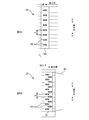
- FIG. 5A shows the first joint 50 in the first embodiment
- FIG. 5B shows the second joint 51 in the first embodiment.
- the number of welding regions 52 and 53 included in the first joint portion 50 and the second joint portion 51 is drawn smaller than the actual number.
- the first joint portion 50 has eight substantially rectangular welding regions 52, specifically, eight so-called saddle-shaped welding regions 52 whose rectangular short sides are curved.
- the eight welding regions 52 are arranged in a line at a predetermined interval d1 in the vertical direction.
- the second bonding portion 51 has 16 welding regions 53 having the same shape and the same size as the welding regions 53 included in the first bonding portion 50.
- the 16 welding regions 53 are arranged in two rows in the horizontal direction while being arranged at a predetermined interval d2 in the vertical direction.
- the pattern of the plurality of weld regions 52 in the first joint portion 50 is different from the pattern of the plurality of weld regions 53 in the second joint portion 51.
- the number of welded regions 53 included in the second joint portion 51 is larger.
- the vertical interval d2 in which the weld regions 53 of the second joint 51 are arranged is narrower than the vertical interval d1 in which the weld regions 52 of the first joint 50 are arranged.
- the ratio (A2 / A1) of the area (A2) occupied by the plurality of welding regions 53 of the second joint portion 51 in the area (A1) of the entire region of the second joint portion 51 is the first joint portion 50. Is larger than the ratio (A4 / A3) of the area (A4) occupied by the plurality of welding regions 52 of the first joint portion 50 in the total area (A3). Therefore, the bonding strength of the second bonding portion 51 is greater than the bonding strength of the first bonding portion 50, the second bonding portion 51 is not easily damaged during mounting, and the first bonding portion 50 is easily peeled off during replacement. .
- Example 2 shows the first joint 50 in the second embodiment
- FIG. 6B shows the second joint 51 in the second embodiment
- the number of the welding regions 52 and 53 is the same (eight) in the first joint portion 50 and the second joint portion 51
- the vertical interval d1 in which the weld regions 52 and 53 are arranged is the same.
- the weld region 52 of the first joint 50 and the weld region 53 of the second joint 51 have the same shape (saddle shape), but compared to the weld region 52 of the first joint 50, the second joint 51.
- the welding region 53 is larger.
- Example 2 the pattern of the plurality of welding regions 52 in the first joint portion 50 is different from the pattern of the plurality of welding regions 53 in the second joint portion 51, and the welding region 52 of the first joint portion 50 is different.
- the welding region 53 of the second joint portion 51 is larger. Therefore, the ratio (A2 / A1) of the area (A2) occupied by the plurality of welding regions 53 of the second joint portion 51 in the area (A1) of the entire region of the second joint portion 51 is the first joint portion 50. Is larger than the ratio (A4 / A3) of the area (A4) occupied by the plurality of welding regions 52 of the first joint portion 50 in the total area (A3).
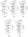
- FIGS. 7A to 7C are diagrams illustrating the second joint portion 51 in the third embodiment.
- the welding region 53 of the second joint portion 51 shown in FIG. 7A has the same substantially rectangular shape (saddle shape) as the welding region 53 of the first embodiment. However, the directions are different, and in the welding region 53 of Example 3, the long side is along the vertical direction.
- the welding region 53 shown in FIG. 7B has a square shape, and the sides are along the vertical direction.
- the welding region 53 shown in FIG. 7C has a triangular shape, and one side of the three sides extends along the vertical direction and is located on the inner side (one side) in the horizontal direction.
- the end 53e on the laterally inner side (one side) of the welding region 53 of the second joint 51 is formed. Force acts. Therefore, if the end 53e is, for example, a vertex of a triangle or a point on an arc, the end 53e becomes a starting point of breakage. Therefore, as in the welding region 53 shown in FIGS. 7A to 7C, the inner end 53 e in the horizontal direction of the welding region 53 may have a predetermined length along the vertical direction. By doing so, the end 53e is less likely to be a starting point of breakage, and the second joint 51 is less likely to be damaged.
- the inner end 53e in the horizontal direction of the welding region 53 is along the vertical direction is not limited to the case where the end 53e and the vertical direction are parallel to each other, and includes the case where the end 53e intersects the vertical direction. . Even in the case of crossing, compared to the case where the end 53e is a point, the end 53e is less likely to be a starting point of breakage, and the second joint portion 51 is less likely to be damaged.
- the shape of the welding region 53 in the third embodiment is not limited to that shown in FIG. 7, and may be, for example, a polygon such as a pentagon, a semicircle, or the like. To be located.
- the ratio of the area occupied by the welded regions 52 and 53 is larger than that of the first joint portion 50 so that the joint strength of the second joint portion 51 is larger than the joint strength of the first joint portion 50. Therefore, it is preferable to make the second joint portion 51 larger. Therefore, as in the first and second embodiments, the number of the welding regions 52 may be reduced or the size of the first bonding portion 50 may be reduced as compared with the second bonding portion 52. Moreover, the shape of the welding area
- Example 4 8A to 8E are diagrams illustrating the first joint portion 50 according to the fourth embodiment.
- the weld region 52 of the first joint 50 shown in FIGS. 8A to 8C has a triangular shape.
- one vertex is positioned on the upper side in the vertical direction
- the welding region 52 of FIG. 8B one vertex is positioned on the lower side in the vertical direction
- the welding region 52 of FIG. It is located in a direction inclined inward (on the other side) in the horizontal direction toward the upper side in the vertical direction.
- the welding region 52 shown in FIG. 8E has a rhombus shape, with one vertex located on the upper side in the vertical direction and one vertex located on the lower side.
- the horizontal length d3 is the shortest at the upper end in the vertical direction
- the horizontal length d3 is the shortest at the lower end in the vertical direction in the welded region 52 of FIG. 8B.
- the horizontal length d3 is the shortest at the upper end and the lower end in the vertical direction. That is, in the welding region 52 of the first joint portion 50 according to the fourth embodiment, the horizontal length d3 of at least one of the upper end portion and the lower end portion in the vertical direction is the shortest. Therefore, in the welding region 52 of the first joint portion 50, the joint strength is the weakest at the upper end portion and the lower end portion in the vertical direction.
- the first joint portion 50 When the diaper is replaced, the first joint portion 50 is peeled off along the vertical direction, and a vertical force acts on the first joint portion 50. Therefore, the upper end part and lower end part of the welding area 52 become the starting point of peeling by weakening the joining strength of the upper end part and the lower end part of the welding area 52 of the first joint part 50. Therefore, the first joint 50 can be easily peeled off, and the diaper 1 can be easily replaced.
- the exchanger of the diaper 1 puts a finger inside the rear waistline portion 20 and the front waistline portion 30 to peel it off. Therefore, at the start of peeling, a force in a direction inclined with respect to the vertical direction from the inner side in the horizontal direction to the outer side acts on the first joint portion 50. For this reason, for example, as in the welding region 52 of FIG. 8C, one of the vertices of the triangle is positioned in a direction inclined outward in the horizontal direction toward the lower side in the vertical direction, and another apex is directed toward the upper side in the vertical direction. And in a direction inclined laterally outward.
- the apex of the welding region 52 becomes the starting point of the peeling, and the first joint portion 50 is more easily peeled off.
- region 52 of FIG. 8A since one of the vertices of a triangle is located in the direction which inclined to the outer side of the horizontal direction toward the upper side of the vertical direction, it is easy to peel off from the lower side of the vertical direction.
- 8B and 8D since the apex of the triangle and the apex of the curved short side are located in a direction inclined outward in the horizontal direction toward the lower side in the vertical direction, the upper side in the vertical direction It is easy to peel off from.
- the ratio of the area occupied by the welded regions 52 and 53 is larger than that of the first joint portion 50 so that the joint strength of the second joint portion 51 is larger than the joint strength of the first joint portion 50. Therefore, it is preferable to make the second joint portion 51 larger. Therefore, as in the first and second embodiments, the number of the welding regions 52 may be reduced or the size of the first bonding portion 50 may be reduced as compared with the second bonding portion 52. Moreover, since it is not necessary to peel off the 2nd junction part 51, it is preferable that the shape of the welding area
- region 53 of the 2nd junction part 51 is a shape shown in Example 3 instead of the shape shown in FIG.
- the number of the welding regions 52 is not limited to the uniform arrangement along the vertical direction, and the number of the welding regions 52 is reduced at the upper end portion and the lower end portion of the first bonding portion 50 as compared with the central portion. Or may be reduced in size. By doing so, since the bonding strength is weak at the upper end portion and the lower end portion of the first bonding portion 50, the first bonding portion 50 is more easily peeled off.
- the method of increasing the bonding strength of the second bonding portion 51 than the bonding strength of the first bonding portion 50 is not limited to the method of increasing the proportion of the area occupied by the welding region 53.
- the bonding strength of each welding region 53 of the second bonding portion 51 may be greater than the bonding strength of each welding region 52 of the first bonding portion 50.
- the number of sheets stacked and the basis weight of fibers are increased in the second bonding portion 51 than in the first bonding portion 50, and the pressure applied during welding is increased or the welding time is increased. Or make it longer.
- the vertical length H ⁇ b> 2 of the second joint portion 51 is shorter than the vertical length H ⁇ b> 4 of the first joint portion 50.
- the length H2 may be equal to the length H4, or the length H2 may be longer than the length H4.
- the length H2 in the vertical direction of the second joint portion 51 may be longer than half the length H1 of the end 20e on the other side in the horizontal direction of the rear waistline portion 20 (H2> H1 / 2).
- FIG. 10A is a schematic plan view showing an example of the position of the locking portion 41 when worn
- FIG. 10B is a schematic view when the diaper 1 in the state of FIG. 10A is viewed from above.
- a so-called pants-type diaper that is, a diaper in which a rear waistline portion and a front waistline portion are joined to each other at both lateral ends, the joint portions are located on both sides of the wearer. And the soft site
- the soft part of the front waistline part receives a downward force from the stomach of the wearer, and the diaper tends to shift downward.
- the first joint portion 50 which is a joint portion between the rear waistline portion 20 and the front waistline portion 30, is one side of the wearer.
- the 2nd junction part 51 which is a junction part of the back waistline part 20 and the latching member 40 is located in a wearer's front (abdomen).
- the end 41 e end on the other side in the lateral direction
- the locking portion 41 on the second joint portion 51 side is the absorbent main body 10 (the crotch portion).
- the second bonding portion 51 is It is located on the front side of the position of one joint 50.
- the rigidity of the second joint portion 51 is relatively high.
- the 2nd junction part 51 with the high rigidity is located in a wearer's front (abdomen)
- the protrusion of a wearer's stomach can be supported by the 2nd junction part 51.
- FIG. Therefore, the position shift to the downward direction of the diaper 1 (front waistline part 30) by the protrusion of a wearer's stomach can be suppressed, and the wearing property of the diaper 1 becomes favorable.
- the bonding strength of the second bonding portion 51 is larger than the bonding strength of the first bonding portion 50, and the rigidity of the second bonding portion 51 is higher. Therefore, the protrusion of the wearer's stomach can be firmly supported by the second joint portion 51, and the downward displacement of the diaper 1 due to the protrusion of the wearer's stomach can be more reliably suppressed.
- the end 34 e on the other side in the horizontal direction of the target region 34 and the end 10 e on the other side in the horizontal direction of the absorbent main body 10 coincide with each other.
- the wearer of the diaper 1 makes the locking portion 41 fit in the target region 34 so that the locking member 40 is firmly locked to the front waistline portion 30. That is, it is highly probable that the end 41e on the other side in the lateral direction of the locking portion 41 is located on the inner side (one side) in the lateral direction than the end 10e on the other side in the lateral direction of the absorbent main body 10. Therefore, as shown in FIG.
- the second joint portion 51 can be positioned in front of the position of the first joint portion 50. it can.
- the rigidity at the second joint portion 51 is larger than the rigidity at the front waistline portion 30. This is because the second bonding portion 51 has a highly rigid welding region 53, whereas the front waistline portion 30 is formed of a skin side sheet 31 such as a soft nonwoven fabric and a non-skin side sheet 32. is there. Even if the second joint portion 51 and the front waistline portion 30 have the same rigidity, in the diaper 1, the second joint portion 51 and the front waistline portion 30 are in the front-rear direction (thickness direction) in front of the wearer. Is superimposed on. Therefore, compared with the underpants type diaper which does not have the 2nd junction part 51 ahead of a wearer, position shift to the lower part of diaper 1 can be controlled.
- the support with respect to the position shift of the front waistline part 30 becomes more reliable, and the diaper 1 by the protrusion of a wearer's stomach is improved.
- the downward displacement is further suppressed.
- segmented the value measured by the Gurley bending resistance by the length of the sample piece can be illustrated, for example.
- the Gurley bending resistance can be measured according to JIS-L1096 using a No. 311 Gurley type flexibility tester manufactured by Yasuda Seiki Seisakusho.
- the two sheets of the skin side sheet 31 and the non-skin side sheet 32 overlap, whereas in the second joint portion 51, FIG. 4B and FIG.
- seat 43 of the latching member 40 have overlapped a total of four sheets. That is, the number of members overlapping in the second joint portion 51 is greater than the number of members overlapping in the front waistline portion 30.
- the rigidity in the 2nd junction part 51 is larger, and the position shift to the downward direction of the diaper 1 by the protrusion of a wearer's stomach can be suppressed more reliably.
- the rigidity of the second joint portion 51 can be made larger than the rigidity of the front waistline portion 30.
- the longitudinal length H2 of the second joint portion 51 is shorter than the longitudinal length H1 of the end portion on the other lateral side of the rear waistline portion 20.
- it may be equal to the length H1. That is, you may provide the 2nd junction part 51 ranging from the upper end of the edge part of the horizontal direction other side of the back waistline part 20 to a lower end.
- the elastic member included in the diaper 1 is not limited to a thread-like elastic member such as rubber thread, but may be a sheet-like elastic member, for example.
- segmented into three parts was illustrated, it is not restricted to this, The diaper in which the back waistline part 20 and the front waistline part 30 were formed integrally, the back waistline part 20, the front waistline part 30 and a diaper in which the absorbent main body 10 is integrally formed.
- the wear object of the diaper 1 is made into the infant in the said embodiment, adults, such as elderly people, are good also as a wear object.
- the absorbent article is not limited to being used as a diaper, but may be used as a sanitary product, for example.
- the lengths H1 to H4, L1 to L6, d, and d1 to d3 shown in FIGS. 2, 3, 5, 6, and 8 are compared with each other. This is a comparison in a state where the portion 20 and the front waistline portion 30 are extended.
- the “extended state” refers to a state in which the absorbent main body 10 is extended in the vertical direction, and the rear waistline portion 20 and the front waistline portion 30 are extended in the horizontal direction.
- a state in which the longitudinal dimension of the absorbent main body 10 is elongated in the longitudinal direction until the longitudinal dimension is the same as or close to the longitudinal dimension of the topsheet 12, and the lateral direction of the rear waistline portion 20 A state in which the size of the skin side sheet 21 and the non-skin side sheet 22 are the same as, or close to, the length in the lateral direction, and the front waistline portion. 30 is a state in which the lateral dimension is extended in the lateral direction until the lateral dimension of the skin-side sheet 31 and the lateral dimension of the non-skin-side sheet 32 are the same or close to these dimensions. .
- SYMBOLS 1 Diaper (absorbent article), 10 absorptive main body (crotch lower part), 11 absorber, 12 surface sheet, 13 back sheet, 20 back waistline part, 21 skin side sheet, 22 non-skin side sheet, 23 thread rubber, 30 Front waistline part, 31 skin side sheet, 32 non-skin side sheet, 33 thread rubber, 34 target area, 40 locking member, 41 locking part, 42 skin side sheet, 43 non skin side sheet, 50 first joint part, 51 2nd joint part, 52 welding area
Landscapes
- Health & Medical Sciences (AREA)
- Epidemiology (AREA)
- Engineering & Computer Science (AREA)
- Biomedical Technology (AREA)
- Heart & Thoracic Surgery (AREA)
- Vascular Medicine (AREA)
- Life Sciences & Earth Sciences (AREA)
- Animal Behavior & Ethology (AREA)
- General Health & Medical Sciences (AREA)
- Public Health (AREA)
- Veterinary Medicine (AREA)
- Absorbent Articles And Supports Therefor (AREA)
Abstract
L'invention concerne un article absorbant (1) comprenant : une partie de taille avant (30) qui possède une direction longitudinale, une direction latérale, et une direction avant-arrière, et qui se situe le long de la direction latérale ; une partie de taille arrière (20) située le long de la direction latérale ; et une partie d'entrejambe (10) disposée entre la partie de taille avant (30) et la partie de taille arrière (20). Une partie d'extrémité se situant sur un côté de la partie de taille arrière (10), dans la direction latérale, et une partie d'extrémité se situant sur un côté de la partie de taille avant (30), dans la direction latérale, sont liaisonnées par une première partie de liaison (50). Une partie d'extrémité se situant sur l'autre côté de la partie de taille arrière (10), dans la direction latérale, est liaisonnée par une seconde partie de liaison (51) à un élément de blocage (40) comprenant une partie de blocage (41) pouvant se bloquer sur la partie de taille avant (30) lors du port de l'article absorbant. Cet article absorbant est caractérisé en ce que la force de liaison de la seconde partie de liaison (51) est supérieure à la force de liaison de la première partie de liaison (50).
Priority Applications (3)
| Application Number | Priority Date | Filing Date | Title |
|---|---|---|---|
| EP16881518.1A EP3372213B1 (fr) | 2015-12-28 | 2016-10-19 | Article absorbant |
| US16/066,314 US20190008703A1 (en) | 2015-12-28 | 2016-10-19 | Absorbent article |
| CN201680076693.XA CN108430418B (zh) | 2015-12-28 | 2016-10-19 | 吸收性物品 |
Applications Claiming Priority (2)
| Application Number | Priority Date | Filing Date | Title |
|---|---|---|---|
| JP2015256834A JP6412861B2 (ja) | 2015-12-28 | 2015-12-28 | 吸収性物品 |
| JP2015-256834 | 2015-12-28 |
Publications (1)
| Publication Number | Publication Date |
|---|---|
| WO2017115538A1 true WO2017115538A1 (fr) | 2017-07-06 |
Family
ID=59224927
Family Applications (1)
| Application Number | Title | Priority Date | Filing Date |
|---|---|---|---|
| PCT/JP2016/080991 Ceased WO2017115538A1 (fr) | 2015-12-28 | 2016-10-19 | Article absorbant |
Country Status (6)
| Country | Link |
|---|---|
| US (1) | US20190008703A1 (fr) |
| EP (1) | EP3372213B1 (fr) |
| JP (1) | JP6412861B2 (fr) |
| CN (1) | CN108430418B (fr) |
| TW (1) | TW201731471A (fr) |
| WO (1) | WO2017115538A1 (fr) |
Cited By (1)
| Publication number | Priority date | Publication date | Assignee | Title |
|---|---|---|---|---|
| JP2018183486A (ja) * | 2017-04-27 | 2018-11-22 | 日本製紙クレシア株式会社 | パンツタイプ吸収性物品 |
Families Citing this family (4)
| Publication number | Priority date | Publication date | Assignee | Title |
|---|---|---|---|---|
| JP6427484B2 (ja) * | 2015-12-28 | 2018-11-21 | ユニ・チャーム株式会社 | 吸収性物品 |
| JP6789273B2 (ja) * | 2018-10-01 | 2020-11-25 | ユニ・チャーム株式会社 | 吸収性物品 |
| IT201900019785A1 (it) * | 2019-10-25 | 2021-04-25 | Fameccanica Data Spa | Procedimento e apparecchiatura per la produzione di articoli sanitari assorbenti e relativo articolo sanitario assorbente |
| JP7535023B2 (ja) * | 2021-09-17 | 2024-08-15 | 大王製紙株式会社 | 使い捨て着用物品 |
Citations (6)
| Publication number | Priority date | Publication date | Assignee | Title |
|---|---|---|---|---|
| JPH045826U (fr) | 1990-05-01 | 1992-01-20 | ||
| JPH0631721U (ja) * | 1992-10-08 | 1994-04-26 | トーヨー衛材株式会社 | パンツ型使い捨ておむつ |
| JP2003339772A (ja) * | 2002-05-29 | 2003-12-02 | Crecia Corp | パンツ型使い捨ておむつ |
| JP2008104874A (ja) * | 2006-09-29 | 2008-05-08 | Daio Paper Corp | 紙おむつ及びその製造における外装シート部分の形成方法 |
| JP2011147608A (ja) * | 2010-01-21 | 2011-08-04 | Unicharm Corp | パンツ型の使い捨て着用物品 |
| JP2012125483A (ja) * | 2010-12-17 | 2012-07-05 | Kao Corp | 使い捨ておむつ |
Family Cites Families (4)
| Publication number | Priority date | Publication date | Assignee | Title |
|---|---|---|---|---|
| CN101568314A (zh) * | 2006-12-22 | 2009-10-28 | Sca卫生用品公司 | 裤型吸收物品以及制造裤型吸收物品的方法 |
| CN103876897B (zh) * | 2006-12-22 | 2015-11-18 | Sca卫生用品公司 | 裤型吸收物品以及制造裤型吸收物品的方法 |
| JP5065793B2 (ja) * | 2007-07-31 | 2012-11-07 | 大王製紙株式会社 | パンツ型使い捨て紙おむつ |
| CN103237533B (zh) * | 2010-11-30 | 2015-09-02 | 花王株式会社 | 一次性尿布及其制造方法 |
-
2015
- 2015-12-28 JP JP2015256834A patent/JP6412861B2/ja active Active
-
2016
- 2016-10-19 US US16/066,314 patent/US20190008703A1/en not_active Abandoned
- 2016-10-19 CN CN201680076693.XA patent/CN108430418B/zh active Active
- 2016-10-19 EP EP16881518.1A patent/EP3372213B1/fr active Active
- 2016-10-19 WO PCT/JP2016/080991 patent/WO2017115538A1/fr not_active Ceased
- 2016-11-21 TW TW105138098A patent/TW201731471A/zh unknown
Patent Citations (6)
| Publication number | Priority date | Publication date | Assignee | Title |
|---|---|---|---|---|
| JPH045826U (fr) | 1990-05-01 | 1992-01-20 | ||
| JPH0631721U (ja) * | 1992-10-08 | 1994-04-26 | トーヨー衛材株式会社 | パンツ型使い捨ておむつ |
| JP2003339772A (ja) * | 2002-05-29 | 2003-12-02 | Crecia Corp | パンツ型使い捨ておむつ |
| JP2008104874A (ja) * | 2006-09-29 | 2008-05-08 | Daio Paper Corp | 紙おむつ及びその製造における外装シート部分の形成方法 |
| JP2011147608A (ja) * | 2010-01-21 | 2011-08-04 | Unicharm Corp | パンツ型の使い捨て着用物品 |
| JP2012125483A (ja) * | 2010-12-17 | 2012-07-05 | Kao Corp | 使い捨ておむつ |
Non-Patent Citations (1)
| Title |
|---|
| See also references of EP3372213A4 |
Cited By (1)
| Publication number | Priority date | Publication date | Assignee | Title |
|---|---|---|---|---|
| JP2018183486A (ja) * | 2017-04-27 | 2018-11-22 | 日本製紙クレシア株式会社 | パンツタイプ吸収性物品 |
Also Published As
| Publication number | Publication date |
|---|---|
| JP2017118968A (ja) | 2017-07-06 |
| EP3372213B1 (fr) | 2021-02-17 |
| CN108430418A (zh) | 2018-08-21 |
| US20190008703A1 (en) | 2019-01-10 |
| JP6412861B2 (ja) | 2018-10-24 |
| CN108430418B (zh) | 2021-09-28 |
| EP3372213A4 (fr) | 2018-12-26 |
| TW201731471A (zh) | 2017-09-16 |
| EP3372213A1 (fr) | 2018-09-12 |
Similar Documents
| Publication | Publication Date | Title |
|---|---|---|
| JP5568369B2 (ja) | パンツ型吸収性物品 | |
| JP5614899B2 (ja) | パンツ型吸収性物品 | |
| JP6407693B2 (ja) | 使い捨て着用物品 | |
| JP6412861B2 (ja) | 吸収性物品 | |
| JP5866045B1 (ja) | 吸収性物品 | |
| KR20170036041A (ko) | 일회용 기저귀 | |
| AU2015293070B2 (en) | Disposable diaper | |
| WO2006093295A1 (fr) | Article jetable a porter sur le corps | |
| CN103997998B (zh) | 一次性穿着物品 | |
| JP6415318B2 (ja) | 開放型の使い捨て着用物品 | |
| JP2018199061A (ja) | 吸収性物品 | |
| JP5721395B2 (ja) | 吸収性物品 | |
| JP3211442U (ja) | パンツ型の着用物品 | |
| CN108430415B (zh) | 吸收性物品 | |
| JP3210619U (ja) | パンツ型吸収性物品 | |
| JP2016002391A (ja) | パンツ型吸収性物品 | |
| JP2017086565A (ja) | 使い捨ておむつ | |
| JP2016010433A (ja) | パンツ型吸収性物品 | |
| JP6316707B2 (ja) | パンツ型吸収性物品 | |
| JP6567816B2 (ja) | 使い捨てのおむつ | |
| JP2019177294A (ja) | 使い捨ておむつ | |
| JP6272106B2 (ja) | パンツ型の着用物品 | |
| JP2008055001A (ja) | 紙おむつ | |
| JP3210618U (ja) | パンツ型吸収性物品 | |
| JP6181365B2 (ja) | 吸収性物品 |
Legal Events
| Date | Code | Title | Description |
|---|---|---|---|
| 121 | Ep: the epo has been informed by wipo that ep was designated in this application |
Ref document number: 16881518 Country of ref document: EP Kind code of ref document: A1 |
|
| WWE | Wipo information: entry into national phase |
Ref document number: 2016881518 Country of ref document: EP |
|
| NENP | Non-entry into the national phase |
Ref country code: DE |