WO2017115594A1 - Outil électrique - Google Patents
Outil électrique Download PDFInfo
- Publication number
- WO2017115594A1 WO2017115594A1 PCT/JP2016/084954 JP2016084954W WO2017115594A1 WO 2017115594 A1 WO2017115594 A1 WO 2017115594A1 JP 2016084954 W JP2016084954 W JP 2016084954W WO 2017115594 A1 WO2017115594 A1 WO 2017115594A1
- Authority
- WO
- WIPO (PCT)
- Prior art keywords
- motor
- switch
- circuit
- electric tool
- switching element
- Prior art date
- Legal status (The legal status is an assumption and is not a legal conclusion. Google has not performed a legal analysis and makes no representation as to the accuracy of the status listed.)
- Ceased
Links
Images


Classifications
-
- H—ELECTRICITY
- H02—GENERATION; CONVERSION OR DISTRIBUTION OF ELECTRIC POWER
- H02P—CONTROL OR REGULATION OF ELECTRIC MOTORS, ELECTRIC GENERATORS OR DYNAMO-ELECTRIC CONVERTERS; CONTROLLING TRANSFORMERS, REACTORS OR CHOKE COILS
- H02P29/00—Arrangements for regulating or controlling electric motors, appropriate for both AC and DC motors
- H02P29/0016—Control of angular speed of one shaft without controlling the prime mover
- H02P29/0022—Controlling a brake between the prime mover and the load
-
- B—PERFORMING OPERATIONS; TRANSPORTING
- B24—GRINDING; POLISHING
- B24B—MACHINES, DEVICES, OR PROCESSES FOR GRINDING OR POLISHING; DRESSING OR CONDITIONING OF ABRADING SURFACES; FEEDING OF GRINDING, POLISHING, OR LAPPING AGENTS
- B24B23/00—Portable grinding machines, e.g. hand-guided; Accessories therefor
- B24B23/02—Portable grinding machines, e.g. hand-guided; Accessories therefor with rotating grinding tools; Accessories therefor
-
- B—PERFORMING OPERATIONS; TRANSPORTING
- B25—HAND TOOLS; PORTABLE POWER-DRIVEN TOOLS; MANIPULATORS
- B25F—COMBINATION OR MULTI-PURPOSE TOOLS NOT OTHERWISE PROVIDED FOR; DETAILS OR COMPONENTS OF PORTABLE POWER-DRIVEN TOOLS NOT PARTICULARLY RELATED TO THE OPERATIONS PERFORMED AND NOT OTHERWISE PROVIDED FOR
- B25F5/00—Details or components of portable power-driven tools not particularly related to the operations performed and not otherwise provided for
- B25F5/02—Construction of casings, bodies or handles
-
- H—ELECTRICITY
- H02—GENERATION; CONVERSION OR DISTRIBUTION OF ELECTRIC POWER
- H02P—CONTROL OR REGULATION OF ELECTRIC MOTORS, ELECTRIC GENERATORS OR DYNAMO-ELECTRIC CONVERTERS; CONTROLLING TRANSFORMERS, REACTORS OR CHOKE COILS
- H02P29/00—Arrangements for regulating or controlling electric motors, appropriate for both AC and DC motors
- H02P29/02—Providing protection against overload without automatic interruption of supply
- H02P29/024—Detecting a fault condition, e.g. short circuit, locked rotor, open circuit or loss of load
- H02P29/027—Detecting a fault condition, e.g. short circuit, locked rotor, open circuit or loss of load the fault being an over-current
-
- B—PERFORMING OPERATIONS; TRANSPORTING
- B23—MACHINE TOOLS; METAL-WORKING NOT OTHERWISE PROVIDED FOR
- B23D—PLANING; SLOTTING; SHEARING; BROACHING; SAWING; FILING; SCRAPING; LIKE OPERATIONS FOR WORKING METAL BY REMOVING MATERIAL, NOT OTHERWISE PROVIDED FOR
- B23D45/00—Sawing machines or sawing devices with circular saw blades or with friction saw discs
- B23D45/16—Hand-held sawing devices with circular saw blades
-
- B—PERFORMING OPERATIONS; TRANSPORTING
- B24—GRINDING; POLISHING
- B24B—MACHINES, DEVICES, OR PROCESSES FOR GRINDING OR POLISHING; DRESSING OR CONDITIONING OF ABRADING SURFACES; FEEDING OF GRINDING, POLISHING, OR LAPPING AGENTS
- B24B27/00—Other grinding machines or devices
- B24B27/06—Grinders for cutting-off
- B24B27/08—Grinders for cutting-off being portable
-
- B—PERFORMING OPERATIONS; TRANSPORTING
- B24—GRINDING; POLISHING
- B24B—MACHINES, DEVICES, OR PROCESSES FOR GRINDING OR POLISHING; DRESSING OR CONDITIONING OF ABRADING SURFACES; FEEDING OF GRINDING, POLISHING, OR LAPPING AGENTS
- B24B47/00—Drives or gearings; Equipment therefor
- B24B47/10—Drives or gearings; Equipment therefor for rotating or reciprocating working-spindles carrying grinding wheels or workpieces
- B24B47/12—Drives or gearings; Equipment therefor for rotating or reciprocating working-spindles carrying grinding wheels or workpieces by mechanical gearing or electric power
-
- B—PERFORMING OPERATIONS; TRANSPORTING
- B24—GRINDING; POLISHING
- B24B—MACHINES, DEVICES, OR PROCESSES FOR GRINDING OR POLISHING; DRESSING OR CONDITIONING OF ABRADING SURFACES; FEEDING OF GRINDING, POLISHING, OR LAPPING AGENTS
- B24B47/00—Drives or gearings; Equipment therefor
- B24B47/26—Accessories, e.g. stops
-
- B—PERFORMING OPERATIONS; TRANSPORTING
- B27—WORKING OR PRESERVING WOOD OR SIMILAR MATERIAL; NAILING OR STAPLING MACHINES IN GENERAL
- B27G—ACCESSORY MACHINES OR APPARATUS FOR WORKING WOOD OR SIMILAR MATERIALS; TOOLS FOR WORKING WOOD OR SIMILAR MATERIALS; SAFETY DEVICES FOR WOOD WORKING MACHINES OR TOOLS
- B27G19/00—Safety guards or devices specially adapted for wood saws; Auxiliary devices facilitating proper operation of wood saws
- B27G19/02—Safety guards or devices specially adapted for wood saws; Auxiliary devices facilitating proper operation of wood saws for circular saws
- B27G19/04—Safety guards or devices specially adapted for wood saws; Auxiliary devices facilitating proper operation of wood saws for circular saws for manually-operated power-driven circular saws
Definitions
- the present invention relates to a power tool.
- the power source 203 forms a closed circuit with the armature 204 and the field coil 205 constituting the motor, and the armature 204
- the tip tool was operated by rotating the tool.
- the trigger switch 202 is turned off, the armature 204 is disconnected from the power source 203 and forms a closed circuit with the brake coil 206.
- the rotation of the armature 204 was braked by the current flowing through the brake coil 206, and the operation of the tip tool was stopped.
- an object of the present invention is to provide an electric tool that can stop a motor even when a trigger switch is on.
- An electric power tool of the present invention is rotated by electric power supplied from a power source and is housed in a housing, a control unit that controls rotation of the motor, and on / off of power supply from the power source to the motor.
- the second braking means can be used without switching the on-state switch off.
- the power supply from the power source to the motor is cut off by a signal from the control unit to brake the motor. Therefore, the driving of the electric tool can be stopped quickly, and unexpected damage to the workpiece can be prevented. Further, when the control unit detects the end of work on the workpiece, the motor can be braked to stop driving the electric tool before turning off the trigger switch.
- the second braking means stops the supply of the electric power from the power source to the motor.
- the motor is quickly braked and the driving of the electric tool is stopped.
- the predetermined signal is a signal output by the control unit when a change greater than a predetermined value related to the motor is detected.
- the predetermined change or more is a change amount of at least one of a rotation speed, a current value, and a position. Therefore, the control unit brakes the motor in response to a predetermined change or more, and can quickly stop the operation of the electric tool without switching the switch off.
- a control circuit including the control unit is provided, the first braking unit is a first closed circuit generated when the switch is switched, and the second braking unit is generated by the control unit.
- the first closed circuit and the second closed circuit are generated in the control circuit.
- the second closed circuit includes a switching element that is turned on by the predetermined signal.
- the first braking means has a brake coil and brakes the motor.
- the braking force of the motor is generated by the coil current flowing through the brake coil, the motor is braked, and the operation of the electric tool is stopped without switching the switch off.
- the motor is a motor with a brush.
- the control unit detects a change greater than or equal to a predetermined value related to the motor, the second braking unit brakes the motor even when the switch is turned on, so that the electric tool can be stopped quickly.
- the second braking means brakes the motor using a brake coil of the first braking means.
- the electric tool can be made small and lightweight.
- the motor is a brushless motor.
- the control unit detects a change greater than or equal to a predetermined value related to the motor, the second braking unit brakes the motor even when the switch is turned on, so that the electric tool can be stopped quickly.
- the electric tool of the present invention since two motor braking means are provided, even if the switch cannot be turned off, the motor is reliably braked and the electric tool is quickly stopped. obtain.
- the circuit diagram of the motor of the conventional electric tool The circuit diagram of the electric tool which concerns on the 1st Embodiment of this invention.
- movement of the electric tool shown in FIG. FIG. 3 is a control waveform diagram of the electric tool shown in FIG. 2.
- the power tool 1 houses a drive circuit 11 including a motor 20 as shown in FIG.
- a control circuit 30 that controls the motor 20 is provided in the drive circuit 11.
- a tip tool is connected to the rotating shaft of the motor 20, and the tip tool is driven by the rotation of the motor 20.
- a power supply PS commercial power supplies AC power to form a first current path IP 1 is connected to the trigger switch 12 in series.
- the motor 20 is a motor with a brush, and includes an armature 21, a field coil 22, and a brake coil 23.
- the armature 21 is provided with a rotating shaft of the motor 20.
- the armature 21 is also referred to as a rotor, a rotor, or an armature.
- Field coil 22 is connected to the armature 21 and the series included in the first current path IP 1.
- the armature 21 is rotated by the magnetic flux generated by the current flowing through the field coil 22.
- the brake coil 23 is connected in series with the armature 21 and brakes the rotation of the armature 21 by a magnetic flux generated by a current flowing through the brake coil 23.
- the field coil 22 and the brake coil 23 are not electrically connected to the armature 21 at the same time.
- the brake coil 23 is a part of the first braking means.
- the trigger switch 12 has an on-contact (ON in FIG. 2) and an off-contact (OFF in FIG. 2), and can be manually switched on and off by an operator to change the contact connected to the motor 20. It is.
- the trigger switch 12 connects the motor 20 to the power source PS when in the on state (when the on contact is selected), and disconnects the motor 20 from the power source PS when it is in the off state (when the off contact is selected).
- On contact of the trigger switch 12 is connected to the first current path IP 1, OFF contact is connected to the second current path IP 2 below.
- the trigger switch 12 is an example of a switch.
- the control circuit 30 includes a control power supply circuit 31, a zero cross detection circuit 32, a rotation speed detection circuit 33 that detects the rotation speed of the motor 20, a current detection circuit 34 that detects a motor current, an acceleration sensor 35, The first switching element 36, the brake control circuit 37, and the microcomputer 38 are included.
- the microcomputer 38 is an example of a control unit.
- the control power supply circuit 31 is a half-wave rectifier circuit including a Zener diode Z, a resistor R1, a diode D1, and a capacitor C1.
- the Zener diode Z has a cathode connected to the first potential G1, an anode connected to the output terminal, and a resistor R1 connected to the anode of the diode D1.
- the cathode of the diode D1 is connected to the node N1 of the first current path IP.
- a capacitor C1 is connected in parallel to the Zener diode Z.
- the Zener diode Z generates a reference voltage Vcc at the output terminal when a voltage higher than the breakdown voltage is applied between the cathode and the anode.
- the reference voltage Vcc is supplied to the microcomputer via the output terminal.
- the zero cross detection circuit 32 includes resistors R2 and R3 and a photocoupler P1. On the input side, between the first current path IP 1 node N1 first potential G1, and the light emitting portion of the resistor R2 and the photocoupler P1 are connected in series. On the output side, the resistor R3 and the light receiving portion of the photocoupler P1 are connected in series between the first potential G1 and Vcc. The zero cross detection circuit 32 detects the zero cross of the AC voltage and outputs it to the microcomputer 38.
- the rotation speed detection circuit 33 includes a rotation speed sensor 40 that detects the rotation speed of the motor 20 and an AC amplification circuit 41 that amplifies the output from the rotation speed sensor 40.
- the AC amplifier circuit 41 includes resistors R4, R5, R6, and R7 and capacitors C2 and C3.
- a resistor R4, a transistor T1, and a resistor R5 are sequentially connected in series between the first potential G1 and Vcc.
- the transistor T1 has a collector connected to the resistor R4 and an emitter connected to the resistor R5.
- a capacitor C2 is connected in parallel to the resistor R5.
- a resistor R6 and a resistor R7 are further connected in series, and a node N2 connecting the resistor R6 and the resistor R7 is connected to the base of the transistor T1.
- the rotation speed sensor 40 has one terminal connected to Vcc and the other terminal connected to the base of the transistor T1 via the capacitor C3 and the node N2.
- the current detection circuit 34 includes a shunt resistor connected in series with the first current path IP 1 and detects a motor current flowing through the motor 20.
- the output of the current detection circuit 34 is input to the microcomputer 38 via the resistor R8.
- the acceleration sensor 35 detects a change in the position of the electric power tool 1, for example, detects the gravitational acceleration when the electric power tool 1 is dropped, and outputs it to the microcomputer 38.
- the first switching element 36 is made of a triac switch the first current path IP 1 on-off are serially connected to the first current path IP 1 (energized state, de-energized state).
- the first switching element 36 is turned on (energized state) by a gate signal input from the microcomputer 38 to the gate terminal of the triac via the resistor R9.
- the rotation angle of the motor is controlled by controlling the conduction angle of the triac according to the input timing of the gate signal.
- the brake control circuit 37 includes a second switching element 45 and a phototriac 46.
- the second switching element 45 includes a triac, and is connected in series between a node N3 between the power source PS and the trigger switch 12 and the brake coil.
- the second switching element 45 is turned on, the trigger switch 12 in the on state, the armature 21 and the brake coil 23 of the motor 20 are sequentially connected in series, and the brake current path of the motor 20 is connected to the second current path IP 2.
- the closed circuit generated at this time that is, the closed circuit including the ON contact, the second switching element 45, the brake coil 23, and the armature 21 is an example of the second closed circuit in the present invention.
- the input portion of the phototriac 46 is connected in series with the resistor R10 between the output terminal of the microcomputer 38 and Vcc.
- the output portion of the phototriac 46 has two resistors R11 and R12 connected to both sides, connected in parallel to the second switching element 45, and one terminal of the output portion connected to the gate terminal of the triac.
- the second switching element 45 is switched on and off.
- the brake control circuit 37 is a part of the second braking means.
- the microcomputer 38 is supplied with power from the control power supply circuit 31 and adjusts the conduction angle of the first switching element 36 based on the output from the zero cross detection circuit 32, the rotation speed detection circuit 33, the current detection circuit 34, or the acceleration sensor 35. To control the rotation of the motor 20.
- the brake control circuit 37 brakes the rotation of the motor 20 and stops the operation of the tip tool.
- the change of the motor 20 more than a predetermined value is an excessive change in the motor 20 due to, for example, a rapid change in the rotation speed of the armature 21 due to the tip tool biting into the machining member (immediately before the kickback occurs) or a load fluctuation of the machining member. For example, the amount of movement of the electric tool 1 including the motor 20 generated when the electric current or kickback occurs or when the electric tool is dropped.
- microcomputer 38 one end of the field coil 22 is connected via a resistor R13 in order to detect the on / off of the trigger switch 12.
- the microcomputer 38 is an example of a control unit.
- Vcc is supplied from the control power supply circuit 31 to predetermined locations of the microcomputer 38 and the control circuit 30.
- a switch-on signal is input to the microcomputer 38 via the resistor R13.
- the microcomputer 38 inputs a gate signal to the gate terminal of the first switching element 36, the first switching element 36 is turned on.
- the first current path IP 1 is energized, the current starts to flow through the armature 21 and the field coil 22 in the motor 20, the rotation of the armature 21 is started by the magnetic flux generated by the field coil 22, and the motor 20 is activated.
- the microcomputer 38 periodically outputs an ON signal for turning on the first switching element 36 to the first switching element 36 in synchronization with the power supply voltage.
- the microcomputer 38 gradually widens the conduction angle of the first switching element 36 by changing the timing at which a gate signal is output from the zero-cross point of the AC power detected by the zero-cross detection circuit 32 to the first switching element 36. Then, control is performed so that the rotation speed of the armature 21 becomes the target rotation speed.
- the microcomputer 38 monitors the rotation speed of the armature 21 detected by the rotation speed detection circuit 33.
- the microcomputer 38 widens the conduction angle of the first switching element 36 when the rotation speed of the armature 21 is lower than the target rotation speed, while the first switching element 36 when the rotation speed of the armature 21 is higher than the target rotation speed.
- phase control is performed by controlling the input timing of the gate signal to the zero cross point, and constant rotation speed control is performed so that the rotation speed of the armature 21 is always constant (step S2).
- the worker turns off the trigger switch 12 (connects the armature 21 to the off contact). Then, a closed circuit including an off contact, a brake coil 23, and an armature 21 is formed in the drive circuit 11.
- the closed circuit formed at this time is an example of the first closed circuit in the present invention.
- the first braking means is means for generating a braking force on the armature 21 by mechanical operation.
- the first closed circuit is part of the first braking means.
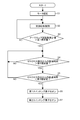
- step S1 When the operator switches on the trigger switch 12, the motor 20 is started in the same manner as in normal work (step S1).
- the microcomputer 38 performs phase control and performs constant rotation speed control so that the rotation speed of the armature 21 is always constant (step S2).
- step S3 the microcomputer 38 compares the amount of decrease in the armature rotation number per unit time with the first specified value to determine the occurrence of kickback (step S3).
- the first predetermined value is a value corresponding to a change in the armature rotational speed that occurs only when the kickback state is entered, and is a value that does not occur in normal work.
- step S3 if the amount of decrease in the number of rotations of the armature 21 per unit time is greater than the first specified value, it is determined that kickback has occurred or may occur (step S3: YES), and the microcomputer 38 Sets the predetermined change detection flag to 1 and proceeds to step S4. On the other hand, when the amount of decrease in the rotational speed per unit time is less than the first specified value, the process returns to step S2, the constant rotational speed control is performed, and the occurrence of the kickback phenomenon is monitored.
- step S4 after the predetermined change detection flag becomes 1, it is determined whether or not the elapsed time from the first occurrence of zero crossing is longer than the second specified value (step S4).
- the second specified value corresponds to the minimum time interval at which the first switching element 36 can be switched on by the input of the gate signal from the zero cross.
- step S4 when the elapsed time from the occurrence of zero crossing is longer than the second specified value (step S4: YES), the process proceeds to step S5.
- step S5 it is determined whether or not the elapsed time is smaller than a third specified value.
- the third specified value is set to a time interval between the zero cross and the zero cross, that is, a time interval shorter than a half cycle of the AC voltage in order to stop the motor 20 reliably in a short time.
- step S5 when the elapsed time is smaller than the third specified value (step S5: YES), the process proceeds to step S6.
- step S ⁇ b> 6 a gate signal is input from the microcomputer 38 to the first switching element 36 to turn on the first switching element 36.
- step S ⁇ b> 6 a gate signal is input from the microcomputer 38 to the first switching element 36 to turn on the first switching element 36.
- a voltage is applied across the second switching element 45.
- step S ⁇ b> 6 a gate signal is input to the second switching element 45 from the microcomputer 38 via the phototriac 46 to turn on the second switching element 45.
- a closed circuit is formed by the on-state trigger switch 12 (on contact), the armature 21, the brake coil 23, and the second switching element 45.
- the closed circuit formed at this time is an example of the second closed circuit in the present invention.
- the magnetic flux generated by the current flowing through the brake coil 23 is added to the magnetic flux generated by the current flowing through the armature 21, and the direction of rotation of the armature 21 is opposite based on the current flowing through the brake coil 23.
- Directional braking force is generated.
- the second braking means in the present invention is a series of flows from when the gate signal is input from the microcomputer 38 to the first switching element 36 to form the second closed circuit and to apply the braking force to the armature 21. It is.
- the second braking means is means for causing the armature 21 to generate a braking force by electronic control.
- the second closed circuit is part of the second braking means.
- step S3 the occurrence of kickback is detected by comparing the amount of decrease in the armature rotational speed per unit time with the first specified value, and the acceleration acting on the housing 10 of the electric tool including the motor 20 by the acceleration sensor 35. It is also possible to detect and compare the detected acceleration with a preset acceleration corresponding to the occurrence of kickback. Further, based on the motor current detected by the current detection circuit 34 detects an overload or overcurrent to the motor 20, by applying a current to the brake coil 23 by the second current path IP 2, the rotation of the armature 21 You can also brake.
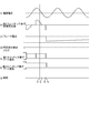
- the microcomputer 38 When the operator switches on the trigger switch 12, the microcomputer 38 turns on the first switching element 36 and starts the motor 20. At this time, since the microcomputer 38 controls the phase of the first switching element 36 with respect to the AC voltage applied to the motor 20, the armature 21 of the motor 20 rotates at the target rotational speed (corresponding to steps S1 and S2, FIG. 4 (a), (e)).
- step S3 the microcomputer 38 detects the occurrence of a kickback (step S3: YES), a predetermined change detection flag is set to 1 from 0 (see FIG. 4 (d)).
- the microcomputer 38 first detects the zero cross of the AC power at the time t 2 , and determines the elapsed time from the time t 2 in steps S 4 and S 5 in FIG. .
- the microcomputer 38 is in the ON state by applying a gate signal to the first switching element 36 (See FIG. 4E).
- the second switching element is a voltage shown in FIG. 4 (b) is applied at time t 4, on the microcomputer 38, the second switching element by inputting a gate signal to the second switching element The state is set (FIG. 4B).
- current flows through the second current path IP 2
- current braking current
- the brake coil 23 see FIG. 4 (c)
- a braking force for braking the rotation of the armature 21 is generated, and the rotation of the motor 20 is stopped.
- the microcomputer 38 detects a kickback stops the application of the gate signal to the first switching element 36.
- the first current path IP 1 is disconnected from the power supply PS.
- the brake current continuously flows while causing a loss due to the resistance component of the second current path IP 2 , so that the braking force continuously acts on the armature 21 to ensure that Stop the rotation of the armature 21.
- the microcomputer 38 detects an overcurrent of the motor current or a drop of the housing 10, the rotation of the motor 20 is braked without turning off the trigger switch 12.
- the operation of the tool 1 can be stopped. That is, when a change of a predetermined value or more is detected in the state (rotation speed, current value, position, etc.) regarding the electric power tool 1, the motor 20 can be braked quickly.
- a current for braking the rotation of the armature 21 can flow through the brake coil 23 regardless of whether the trigger switch 12 is turned off or the second switching element 45 is turned on by the brake control circuit 37. . That is, in this configuration, since the brake coil 23 is shared by both the first braking means and the second braking means, the circuit of the electric tool 1 can be configured in a compact and inexpensive manner.
- a drive circuit 101 is provided in the housing 100 using a commercial power source PS that supplies AC power as a power source.
- the drive circuit 101 includes a rectifier circuit 110, an inverter circuit 120, a brushless motor 130, and a microcomputer 140, and controls driving of the brushless motor 130.
- the rectifier circuit 110 is formed of a diode bridge, and rectifies the output L1 so that the line L1 is on the high potential side and the line L2 is on the low potential side.
- the brushless motor 130 includes a rotor 131 having a permanent magnet and a stator 132.
- the stator 132 is star-connected with a U-phase winding, a V-phase winding, and a W-phase winding.
- the brushless motor 130 is an example of a motor.
- the high potential line L1 between the rectifier circuit 110 and the inverter circuit 120 is provided with a trigger switch 151 that can be switched by an operator and that turns on / off the power supply to the brushless motor 130.
- a capacitor 154 is provided between the rectifier circuit 110 and the inverter circuit 120.
- the inverter circuit 120 includes six switching elements Q1 to Q6.
- the first, second, and third switching elements Q1, Q2, and Q3 are disposed on the high potential line L1 side, and the fourth potential is on the low potential line L2 side.
- the fifth and sixth switching elements Q4, Q5, Q6 are arranged. Further, the first switching element Q1 and the fourth switching element Q4 are connected in series between the high potential line L1 and the low potential line L2, and the second switching element Q2 and the fifth switching element Q5 are connected in series.
- the third switching element Q3 and the sixth switching element Q6 are connected in series.
- a node Vu between the first switching element Q1 and the fourth switching element Q4 is connected to the U-phase winding via the first wiring L4.
- a node Vv between the second switching element Q2 and the fifth switching element Q5 is connected to the U-phase winding via the second wiring L5.
- a node Vw between the third switching element Q3 and the sixth switching element Q6 is connected to the W-phase winding via the third wiring L6.
- the first wiring L4 includes a first auxiliary switch 152 that can be switched on and off.
- the first auxiliary switch is a mechanical switch and electrically connects the node Vu to the U-phase winding when turned on.
- the first auxiliary switch 152 When the first auxiliary switch 152 is turned off, it electrically connects the U-phase winding to the V-phase winding via the resistor R20.
- the third wiring L6 has a second auxiliary switch 153 that can be switched on and off.
- the second auxiliary switch is a mechanical switch, and when turned on, electrically connects node Vw to the W-phase winding.
- the W-phase winding is electrically connected to the V-phase winding via the resistor R21.
- the first auxiliary switch 152 and the second auxiliary switch 153 are configured to be switched on and off in conjunction with the on / off of the trigger switch 151 by the operator. That is, when the trigger switch 151 is turned on by the operator, both the first auxiliary switch 152 and the second auxiliary switch 153 are turned on in conjunction with each other. On the other hand, when the trigger switch 151 is turned off by the operator, both the first auxiliary switch 152 and the second auxiliary switch 153 are turned off in conjunction with each other.
- the trigger switch 151 and the first and second auxiliary switches 152 and 153 may be linked simultaneously.
- the trigger switch 151, the first auxiliary switch 152, and the second auxiliary switch 153 are examples of switches.
- the microcomputer 140 can operate by supplying power from the switching power supply circuit 141.
- the switching power supply circuit 141 is connected to the power supply PS and operates when the trigger switch 151 is turned on.
- the microcomputer 140 controls the rotation of the brushless motor 130 by controlling the switching operation of the inverter circuit 120 based on the output of the hall element 142 provided in the brushless motor 130.
- the microcomputer 140 is an example of a control unit.
- the trigger switch 151, the first and second auxiliary switches 152 and 153, and the stator 132 are examples of the first braking means.
- the microcomputer 140 and the stator 132 are an example of a second braking unit.
- the inverter circuit 120 When the operator switches on the trigger switch 151, power is supplied to the inverter circuit 120, and the inverter circuit 120 starts a switching operation by a control signal from the microcomputer 140. At this time, since the first and second auxiliary switches 152 and 153 are also turned on, the nodes Vu, Vv, and Vw in the inverter circuit 120 perform the switching operations of the first to sixth switching elements Q1 to Q6. Accordingly, the brushless motor 130 is started by being connected to the corresponding U-phase, V-phase, and W-phase windings.
- the microcomputer 140 detects the rotational speed of the rotor 131 based on the output of the hall element 142, and controls the switching operation of the inverter circuit 120 so that the rotational speed of the rotor 131 maintains a predetermined number (step S12).
- the worker turns off the trigger switch 151 and stops supplying power to the inverter circuit 120 and the microcomputer 140.
- the trigger switch 151 is switched, the first and second auxiliary switches 152 and 153 are simultaneously turned off, the U-phase winding is electrically connected to the V-phase winding via the resistor R20, and the W-phase is connected via the resistor R21.
- the phase winding is electrically connected to the V phase winding. Accordingly, the U-phase, V-phase, and W-phase windings are connected to each other in the stator 132, and a closed circuit is formed together with the trigger switch 151 (off contact) in the off state and the resistors R20 and R21.
- the closed circuit formed at this time is an example of the first closed circuit in the present invention.
- the trigger switch 151 When the trigger switch 151 is turned off, the rotor 131 continues to rotate, but a current flows through the first closed circuit due to a magnetic flux change based on the rotation of the rotor 131 including a permanent magnet. Accordingly, electric current is consumed when a current flows through the first closed circuit, that is, the winding of the stator 132, and a braking force acts on the rotation of the rotor 131.
- a series of flows for applying the braking force to the rotor 131 after the trigger switch 151 is turned off is an example of the first braking means in the present invention.
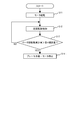
- the brushless motor 130 is activated by a control signal from the microcomputer 140 as in the normal operation (step S11).
- the microcomputer 140 controls the switching operation of the inverter circuit 120 so that the rotation number of the rotor 131 maintains a predetermined number (step S12).
- the microcomputer 140 compares the amount of decrease in the rotor speed per unit time with the fourth specified value to determine the occurrence of kickback (step S13).
- the fourth predetermined value is a value corresponding to a change in the rotational speed of the rotor 131 that occurs only when the kickback state is entered, and is a value that does not occur in normal work.
- step S13 when the amount of decrease in the rotational speed of the rotor 131 per unit time is greater than the fourth specified value, it is determined that kickback has occurred or has occurred (step S13: YES), and the microcomputer 140 proceeds to step S14. Then, all of the first to third switching elements Q1 to Q3 on the high potential line side are turned off by the control signal from the microcomputer 140 to the inverter circuit 120, and the fourth to sixth switching elements Q4 to Q6 on the low potential line side are turned off. One of them, for example, the sixth switching element Q6 is turned off, and the fourth and fifth switching elements Q4 and Q5 are turned on.
- the closed circuit (second circuit) including the low potential line L2, the fourth switching element Q4, the trigger switch 151 (ON contact) in the ON state, the U-phase winding and the V-phase winding of the stator 132, and the fifth switching element Q5 Closed circuit), the electric power generated by the rotation of the rotor 131 is consumed in this closed circuit (converted into heat) to brake the rotation of the rotor 131 (step S14).
- the braking force generated at this time can be changed by turning on / off the fourth switching element Q4 with a PWM signal from the microcomputer 140 and changing the duty ratio during the ON period. As the duty ratio of the ON period becomes longer, the period during which the regenerative current flows becomes longer, so that the braking force increases and the brushless motor 130 can be stopped more quickly.
- step S13 the occurrence of kickback is detected by comparing the amount of decrease in the rotor speed per unit time with the fourth specified value, as well as the acceleration acting on the electric tool 2 detected by the acceleration sensor provided in the housing 10. It can also be performed based on. Further, a current detection circuit is provided in the low potential line L2, and based on the detected motor current, an overload or overcurrent to the brushless motor 130 is detected, the rotation of the rotor 131 is braked, and the electric tool 2 is stopped. You can also.
- the first auxiliary switch 152 and the second auxiliary switch 153 are switched off in conjunction with the trigger switch 151 being switched from on to off.
- the U-phase winding and W-phase winding of the stator 132 and the resistors R20 and R21 are connected in series to form a closed circuit.
- the trigger switch 151 is turned from on to off, a motor current flows in the closed circuit, power is consumed by the resistors R20 and R21, and the motor current gradually decreases. Therefore, when the trigger switch 151 is manually turned off by the operator, the closed circuit operates as a soft brake for the brushless motor 130 and suppresses a sudden braking of the brushless motor 130.
- the microcomputer 140 detects an overcurrent of the motor current or the housing 100 is dropped, even if the trigger switch cannot be turned off, the rotation of the brushless motor 130 is braked, The operation of the power tool can be stopped. That is, when a change of a predetermined value or more is detected in the state (rotation speed, current value, position, etc.) regarding the electric tool, the motor can be braked promptly.
- PS Power source, 1, 2 ... Electric tool, 10,100 ... Housing, 11,101 ... Drive circuit, 12,151 ... Switch, 20 ... Motor with brush, 23 ... Brake coil, 37 ... Brake control circuit, 38,140 ... Microcomputer, 120 ... Inverter circuit, 130 ... Brushless motor
Landscapes
- Engineering & Computer Science (AREA)
- Mechanical Engineering (AREA)
- Power Engineering (AREA)
- Stopping Of Electric Motors (AREA)
- Portable Power Tools In General (AREA)
- Control Of Motors That Do Not Use Commutators (AREA)
Abstract
Priority Applications (4)
| Application Number | Priority Date | Filing Date | Title |
|---|---|---|---|
| CN201680077014.0A CN108602182B (zh) | 2015-12-28 | 2016-11-25 | 电动工具 |
| EP16881574.4A EP3398724B1 (fr) | 2015-12-28 | 2016-11-25 | Outil électrique |
| JP2017558891A JP6701533B2 (ja) | 2015-12-28 | 2016-11-25 | 電動工具 |
| US16/067,049 US10630223B2 (en) | 2015-12-28 | 2016-11-25 | Power tool |
Applications Claiming Priority (2)
| Application Number | Priority Date | Filing Date | Title |
|---|---|---|---|
| JP2015-257446 | 2015-12-28 | ||
| JP2015257446 | 2015-12-28 |
Publications (1)
| Publication Number | Publication Date |
|---|---|
| WO2017115594A1 true WO2017115594A1 (fr) | 2017-07-06 |
Family
ID=59224858
Family Applications (1)
| Application Number | Title | Priority Date | Filing Date |
|---|---|---|---|
| PCT/JP2016/084954 Ceased WO2017115594A1 (fr) | 2015-12-28 | 2016-11-25 | Outil électrique |
Country Status (5)
| Country | Link |
|---|---|
| US (1) | US10630223B2 (fr) |
| EP (1) | EP3398724B1 (fr) |
| JP (1) | JP6701533B2 (fr) |
| CN (1) | CN108602182B (fr) |
| WO (1) | WO2017115594A1 (fr) |
Cited By (4)
| Publication number | Priority date | Publication date | Assignee | Title |
|---|---|---|---|---|
| JP2019098454A (ja) * | 2017-11-30 | 2019-06-24 | 工機ホールディングス株式会社 | 打撃作業機 |
| JP2021509638A (ja) * | 2017-09-21 | 2021-04-01 | ロベルト・ボッシュ・ゲゼルシャフト・ミト・ベシュレンクテル・ハフツングRobert Bosch Gmbh | 工作機械装置、工作機械、及び、工作機械装置を運転するための方法 |
| US20230206368A1 (en) * | 2021-12-29 | 2023-06-29 | Advanced Micro Devices, Inc. | Disabling selected ip |
| JP2024509079A (ja) * | 2021-02-19 | 2024-02-29 | フェストール・ゲゼルシャフト・ミト・ベシュレンクテル・ハフツング | 被加工物を切断するための丸鋸の使用時に定置式ベース構造に対して移動する刃を備えた丸鋸、及びそのような丸鋸のキックバック状態の検出方法 |
Families Citing this family (16)
| Publication number | Priority date | Publication date | Assignee | Title |
|---|---|---|---|---|
| DK3621777T3 (da) * | 2017-07-24 | 2022-10-17 | Festool Gmbh | Elektroværktøj og fremgangsmåde til detektion af en tilbageslagshændelse af et elektroværktøj |
| CN109765048A (zh) * | 2017-11-02 | 2019-05-17 | 南京德朔实业有限公司 | 电动工具以及电动工具反冲的检测方法 |
| DE102018216544A1 (de) * | 2018-09-27 | 2020-04-23 | Robert Bosch Gmbh | Vorrichtung und Verfahren zur sicheren Ablaufsteuerung einer Handwerkzeugmaschine |
| US12506422B2 (en) | 2019-04-25 | 2025-12-23 | Milwaukee Electric Tool Corporation | Motor braking coil for a power tool |
| WO2020251838A1 (fr) | 2019-06-10 | 2020-12-17 | Milwaukee Electric Tool Corporation | Freinage de moteur utilisant une résistance sélectivement connectable |
| CN218788734U (zh) | 2019-12-18 | 2023-04-04 | 米沃奇电动工具公司 | 动力工具及用于动力工具的制动系统 |
| EP3854556B1 (fr) * | 2020-01-22 | 2024-03-06 | Andreas Stihl AG & Co. KG | Procédé de fonctionnement d'un appareil d'usinage guidé à la main et appareil d'usinage guidé à la main |
| JP2021191110A (ja) * | 2020-05-29 | 2021-12-13 | 株式会社マキタ | 電動作業機 |
| SE544811C2 (en) | 2020-10-19 | 2022-11-29 | Husqvarna Ab | A hand-held electrically powered cut-off tool with a kickback mitigation function |
| EP4488006A3 (fr) | 2020-10-19 | 2025-03-26 | Husqvarna AB | Outil de coupure électrique portatif avec fonction d'atténuation de rebond |
| EP4292211A4 (fr) | 2021-02-10 | 2024-10-23 | Techtronic Cordless GP | Dispositif et procédé de freinage de moteur |
| US12090592B2 (en) * | 2021-06-15 | 2024-09-17 | Milwaukee Electric Tool Corporation | Drop detection in power tools |
| WO2023097281A1 (fr) | 2021-11-24 | 2023-06-01 | Milwaukee Electric Tool Corporation | Meuleuse comprenant une détection améliorée et une détection de composant |
| US12134155B2 (en) | 2022-02-28 | 2024-11-05 | Milwaukee Electric Tool Corporation | Power tool including fall detection and autostop |
| CN118805088A (zh) * | 2022-02-28 | 2024-10-18 | 弗劳恩霍夫应用研究促进协会 | 电子元件 |
| SE547813C2 (en) * | 2023-12-22 | 2025-12-02 | Husqvarna Ab | Chainsaw and method for controlling the braking of a chainsaw |
Citations (7)
| Publication number | Priority date | Publication date | Assignee | Title |
|---|---|---|---|---|
| JPS61159176U (fr) * | 1985-03-23 | 1986-10-02 | ||
| JPH03212118A (ja) * | 1990-01-16 | 1991-09-17 | Tachi S Co Ltd | モータの過負荷保護方法および過負荷保護装置 |
| JPH05192027A (ja) * | 1991-11-22 | 1993-08-03 | Sawafuji Electric Co Ltd | 電動式芝刈り機 |
| JPH11215871A (ja) * | 1998-01-27 | 1999-08-06 | Matsushita Electric Works Ltd | モータ制御装置 |
| GB2485276A (en) * | 2010-11-04 | 2012-05-09 | Bosch Gmbh Robert | Switching off an electrical machine tool electronically when a current limit is reached |
| JP2013192512A (ja) * | 2012-03-21 | 2013-09-30 | Kubota Corp | 草刈機 |
| JP2014069301A (ja) * | 2012-10-01 | 2014-04-21 | Ikura Seiki Co Ltd | 可搬形動力工具 |
Family Cites Families (18)
| Publication number | Priority date | Publication date | Assignee | Title |
|---|---|---|---|---|
| JPS6349113Y2 (fr) | 1986-07-10 | 1988-12-16 | ||
| US5063319A (en) * | 1989-05-15 | 1991-11-05 | Black & Decker, Inc. | Universal motor with secondary winding wound with the run field winding |
| IT1258950B (it) * | 1992-06-05 | 1996-03-11 | Black & Decker Inc | Dispositivo di frenatura controllata per motori elettrici, in particolare di utensili portatili |
| US5444318A (en) * | 1994-02-22 | 1995-08-22 | Black & Decker Inc. | Motor with permanent magnet actuated brake |
| US5677586A (en) * | 1994-08-25 | 1997-10-14 | Emerson Electric Co. | Commutation of a universal motor operating in brake mode |
| US6037729A (en) * | 1997-02-06 | 2000-03-14 | Black & Decker Inc. | Apparatus and method for braking electric motors |
| US6236177B1 (en) * | 1998-06-05 | 2001-05-22 | Milwaukee Electric Tool Corporation | Braking and control circuit for electric power tools |
| JP2002027770A (ja) | 2000-07-07 | 2002-01-25 | Hitachi Koki Co Ltd | ブレーキ機能付整流子モータ |
| DE10234397A1 (de) * | 2002-07-23 | 2004-01-29 | C. & E. Fein Gmbh & Co Kg | Gebremster Reihenschlussmotor und Verfahren zum Bremsen eines Reihenschlussmotors |
| US6680596B1 (en) * | 2002-10-10 | 2004-01-20 | S-B Power Tool Corporation | Electric motor having regenerative braking |
| US7023159B2 (en) * | 2002-10-18 | 2006-04-04 | Black & Decker Inc. | Method and device for braking a motor |
| CN201030495Y (zh) * | 2004-04-13 | 2008-03-05 | 布莱克和戴克公司 | 低外形电动磨光机 |
| JP4735325B2 (ja) * | 2006-02-27 | 2011-07-27 | パナソニック電工株式会社 | 電動工具用制御駆動回路 |
| JP4609489B2 (ja) * | 2007-12-25 | 2011-01-12 | パナソニック電工株式会社 | 電動工具 |
| JP5462575B2 (ja) | 2009-10-05 | 2014-04-02 | 株式会社マキタ | 電動工具 |
| JP5351752B2 (ja) * | 2009-12-28 | 2013-11-27 | 株式会社マキタ | 電動工具 |
| JP6155175B2 (ja) * | 2013-11-18 | 2017-06-28 | 株式会社マキタ | 電動工具の制動装置 |
| EP2947765B1 (fr) * | 2014-05-20 | 2020-08-26 | Black & Decker Inc. | Freinage électronique destiné à un moteur universel dans un outil électrique |
-
2016
- 2016-11-25 WO PCT/JP2016/084954 patent/WO2017115594A1/fr not_active Ceased
- 2016-11-25 EP EP16881574.4A patent/EP3398724B1/fr active Active
- 2016-11-25 CN CN201680077014.0A patent/CN108602182B/zh active Active
- 2016-11-25 US US16/067,049 patent/US10630223B2/en active Active
- 2016-11-25 JP JP2017558891A patent/JP6701533B2/ja active Active
Patent Citations (7)
| Publication number | Priority date | Publication date | Assignee | Title |
|---|---|---|---|---|
| JPS61159176U (fr) * | 1985-03-23 | 1986-10-02 | ||
| JPH03212118A (ja) * | 1990-01-16 | 1991-09-17 | Tachi S Co Ltd | モータの過負荷保護方法および過負荷保護装置 |
| JPH05192027A (ja) * | 1991-11-22 | 1993-08-03 | Sawafuji Electric Co Ltd | 電動式芝刈り機 |
| JPH11215871A (ja) * | 1998-01-27 | 1999-08-06 | Matsushita Electric Works Ltd | モータ制御装置 |
| GB2485276A (en) * | 2010-11-04 | 2012-05-09 | Bosch Gmbh Robert | Switching off an electrical machine tool electronically when a current limit is reached |
| JP2013192512A (ja) * | 2012-03-21 | 2013-09-30 | Kubota Corp | 草刈機 |
| JP2014069301A (ja) * | 2012-10-01 | 2014-04-21 | Ikura Seiki Co Ltd | 可搬形動力工具 |
Non-Patent Citations (1)
| Title |
|---|
| See also references of EP3398724A4 * |
Cited By (5)
| Publication number | Priority date | Publication date | Assignee | Title |
|---|---|---|---|---|
| JP2021509638A (ja) * | 2017-09-21 | 2021-04-01 | ロベルト・ボッシュ・ゲゼルシャフト・ミト・ベシュレンクテル・ハフツングRobert Bosch Gmbh | 工作機械装置、工作機械、及び、工作機械装置を運転するための方法 |
| US12151331B2 (en) | 2017-09-21 | 2024-11-26 | Robert Bosch Gmbh | Machine tool device for open-loop and/or closed-loop control of at least one machine tool function of a machine tool |
| JP2019098454A (ja) * | 2017-11-30 | 2019-06-24 | 工機ホールディングス株式会社 | 打撃作業機 |
| JP2024509079A (ja) * | 2021-02-19 | 2024-02-29 | フェストール・ゲゼルシャフト・ミト・ベシュレンクテル・ハフツング | 被加工物を切断するための丸鋸の使用時に定置式ベース構造に対して移動する刃を備えた丸鋸、及びそのような丸鋸のキックバック状態の検出方法 |
| US20230206368A1 (en) * | 2021-12-29 | 2023-06-29 | Advanced Micro Devices, Inc. | Disabling selected ip |
Also Published As
| Publication number | Publication date |
|---|---|
| CN108602182B (zh) | 2022-03-01 |
| US20190013762A1 (en) | 2019-01-10 |
| EP3398724A4 (fr) | 2019-09-25 |
| US10630223B2 (en) | 2020-04-21 |
| JP6701533B2 (ja) | 2020-05-27 |
| EP3398724A1 (fr) | 2018-11-07 |
| EP3398724B1 (fr) | 2023-01-04 |
| CN108602182A (zh) | 2018-09-28 |
| JPWO2017115594A1 (ja) | 2018-10-18 |
Similar Documents
| Publication | Publication Date | Title |
|---|---|---|
| JP6701533B2 (ja) | 電動工具 | |
| JP5743085B2 (ja) | 電動工具 | |
| JP5242974B2 (ja) | 電動工具 | |
| JP3207985U (ja) | モータ駆動システム | |
| CN102640413B (zh) | 具有改进特性的可控直流电机 | |
| US9768713B2 (en) | Electric tool | |
| JP5327514B2 (ja) | 電動工具 | |
| CN100539389C (zh) | 手持式或固定式电动工具和其驱动单元的运行方法 | |
| JP5777924B2 (ja) | 単相直巻整流子電動機の駆動装置 | |
| JP2011016210A (ja) | 電動工具 | |
| JP2015188996A (ja) | 電動工具 | |
| WO2015093056A1 (fr) | Dispositif de commande d'entraînement de moteur, outil électrique et procédé de commande d'entraînement de moteur | |
| JP7124716B2 (ja) | モータ駆動装置、および電動パワーステアリング装置 | |
| KR101690000B1 (ko) | 브레이크를 구비한 전동기 | |
| JP2013111734A (ja) | 電動工具 | |
| JP7074074B2 (ja) | モータ駆動装置、および電動パワーステアリング装置 | |
| JP5808780B2 (ja) | ステッピングモータの回路システムの異常検知装置 | |
| US12506422B2 (en) | Motor braking coil for a power tool | |
| JP5843962B2 (ja) | 安全回路を備えた電気機械 | |
| JP2005176454A (ja) | モータ制御装置およびそれを用いた電動工具 | |
| JP5981321B2 (ja) | 電動工具 | |
| WO2016031715A1 (fr) | Circuit d'attaque de moteur et outil électrique | |
| WO2023074825A1 (fr) | Machine de travail | |
| JP6421835B2 (ja) | 電動工具 | |
| JP2008504974A (ja) | インパクトレンチ |
Legal Events
| Date | Code | Title | Description |
|---|---|---|---|
| 121 | Ep: the epo has been informed by wipo that ep was designated in this application |
Ref document number: 16881574 Country of ref document: EP Kind code of ref document: A1 |
|
| ENP | Entry into the national phase |
Ref document number: 2017558891 Country of ref document: JP Kind code of ref document: A |
|
| NENP | Non-entry into the national phase |
Ref country code: DE |
|
| WWE | Wipo information: entry into national phase |
Ref document number: 2016881574 Country of ref document: EP |
|
| ENP | Entry into the national phase |
Ref document number: 2016881574 Country of ref document: EP Effective date: 20180730 |