WO2017122487A1 - Dispositif pare-soleil - Google Patents
Dispositif pare-soleil Download PDFInfo
- Publication number
- WO2017122487A1 WO2017122487A1 PCT/JP2016/087314 JP2016087314W WO2017122487A1 WO 2017122487 A1 WO2017122487 A1 WO 2017122487A1 JP 2016087314 W JP2016087314 W JP 2016087314W WO 2017122487 A1 WO2017122487 A1 WO 2017122487A1
- Authority
- WO
- WIPO (PCT)
- Prior art keywords
- board
- slider
- guide groove
- state
- boards
- Prior art date
- Legal status (The legal status is an assumption and is not a legal conclusion. Google has not performed a legal analysis and makes no representation as to the accuracy of the status listed.)
- Ceased
Links
Images




Classifications
-
- B—PERFORMING OPERATIONS; TRANSPORTING
- B60—VEHICLES IN GENERAL
- B60J—WINDOWS, WINDSCREENS, NON-FIXED ROOFS, DOORS, OR SIMILAR DEVICES FOR VEHICLES; REMOVABLE EXTERNAL PROTECTIVE COVERINGS SPECIALLY ADAPTED FOR VEHICLES
- B60J7/00—Non-fixed roofs; Roofs with movable panels, e.g. rotary sunroofs
Definitions
- the present invention relates to a multi-plate sunshade device that opens and closes an opening formed in a roof of a vehicle or the like by a plurality of slidable boards.
- sunshade devices to prevent direct sunlight from directly entering the vehicle interior from the sunroof.
- a sunshade device a plurality of rectangular boards (sunshade panels) are provided so as to be slidable in the vehicle front-rear direction, and a drive source is connected to the sunshade panel located at the forefront so that each sunshade panel is interlocked.
- a multi-plate sunshade device that opens and closes an inner opening of a roof (see, for example, Patent Document 1 by the present applicant).
- a plurality of boards overlap each other vertically in one of the openings (for example, the rear of the vehicle) in the stowed state in which the opening is opened, and move forward while being connected to each other in the unfolded state in which the opening is closed.
- a plurality of boards are arranged in the front-rear direction. For this reason, the front board engages with the rear board during the closing operation that shifts from the retracted state to the expanded state, and the front board engages with the rear board during the open operation that shifts from the expanded state to the retracted state. Both boards need to be detachably connected so as to be released.
- a support bracket extends in the front-rear direction at the left and right edges of the board, and a cam pin that protrudes horizontally at the rear end of the support bracket, and the front end of the base of the support bracket
- a connecting mechanism is employed which is formed by a cam groove that extends obliquely downward and rearward on the inner side surface of the cam groove and that has a lower end that opens rearward.
- the upper surface of the front board (more precisely, the upper surface of the support bracket) is placed on the lower surface of the rear board (exactly, the lower surface of the support bracket) in the accommodation position during the opening / closing operation.
- the front board slides below the rear board.
- a semicircular sliding contact portion projects from the lower surface of the support bracket of the rear board, and a clearance is provided between the boards, thereby preventing sliding contact between the boards other than the sliding contact portion.
- a clearance is generated between the boards adjacent in the vertical direction even in the storage state overlapping in the vertical direction, and the height of the board in the storage state is increased. This problem becomes more prominent as the size of one board is reduced and the number of boards is increased in order to reduce the area of the board accommodating portion.
- an object of the present invention is to provide a sunshade device that can reduce the height of a board in a stored state while suppressing sliding contact between the boards.
- the sunshade device (10) is slidably provided to open and close the opening (4), and overlaps each other in the vertical direction behind the opening to open the opening.
- a plurality of boards (11) that can be in a stowed state and a deployed state that closes the opening in the front-rear direction, and an engaged state provided at the front of a rear board among the boards that are lined up in the front-rear direction
- An engaging portion (46) that is disengaged from the engaged portion of the rear board when shifting from the unfolded state to the retracted state, a front slider (32) provided at the front portion of each board, rear A rear slider (42) provided in the front, a guide groove (52B) extending in the front-rear direction to guide the front slider and the rear slider
- the rear slider of the front board is a portion other than the curved portion of the guide groove. Slide Therefore, when the front board slides at a position overlapping the rear board, a clearance is formed between the boards, and sliding contact between the boards is suppressed.
- the front board or its front slider and rear slider may be in contact with the rear board or its front slider and rear slider. Therefore, the clearance between both boards is smaller than the clearance at the time of sliding, and the board height in the stored state is reduced.
- the guide groove (52) may have a sloped portion (64) that slopes toward the rear slider housing portion toward the rear side behind the curved portion (63).
- the rear slider when the board moves forward, the rear slider passes through the inclined portion, so that the rear part of the moving front board has a clearance between the rear part of the rear board in the storage position.
- the rear slider when the board moves backward, the rear slider passes through the inclined portion, so that the rear part of the moving front board reduces the clearance between the rear part of the rear board in the storage position.
- the front slider accommodating portion (61) may extend vertically from the top (63b) of the curved portion (63).
- This configuration makes it possible to maximize the clearance when the front board slides while overlapping the rear board.
- the rear slider accommodating portion (62) may be configured to extend in the vertical direction from the rear end of the inclined portion (64).
- the clearance between the rear portions of both boards can be increased from the moment when the front board overlapping the rear board moves forward from the housed position. Further, when the board moves rearward, the rear slider on the rear board pushes into the rear slider housing part when the rear slider on the front board moves rearward on the inclined portion of the guide groove. That is, it is possible to easily realize a configuration in which the front board is superposed on the rear board to be stored.
- the front slider of the rear board in the storage position can be restricted from moving forward by the restriction member.
- the engaged portion is provided on the lower surface of the front slider, the engaging portion is provided on the upper surface of the rear slider, and the engaging portion is engaged with the engaged portion.
- the front slider and the rear slider are preferably integrated into the guide groove.
- the engaged portion is configured integrally with the front slider and the engaging portion is configured integrally with the rear slider, the component configuration can be simplified. Further, since the front slider and the rear slider that are engaged with each other are integrally received in the guide groove, it is possible to suppress the disengagement of both due to an impact or the like.
- a drive source for driving the board in the front-rear direction via a power transmission member coupled to the board provided in the foremost position in the unfolded state.
- the sunshade device can be motorized with a simple configuration.
- Rear cross-sectional view of the sunshade device in the unfolded state (cross-section VIII-VIII in Fig. 1)
- Explanatory drawing of operating procedure of sunshade device Explanatory drawing of operating procedure of sunshade device
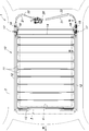
- FIG. 1 is a plan view of the roof of a vehicle 1 (automobile) to which the sunshade device 10 is applied.
- the roof outer plate 2 of the vehicle 1 is formed with a rectangular opening (hereinafter referred to as an outer opening 3) indicated by a virtual line.
- the outer opening 3 is closed by a glass panel.
- the ceiling on the passenger compartment side is constituted by an interior plate arranged below the roof outer plate 2. Also on the interior plate, a rectangular opening (hereinafter referred to as an inner opening 4) indicated by a virtual line smaller than the outer opening 3 is formed below the outer opening 3.
- the inner opening 4 is opened and closed by a plurality of (in this embodiment, ten) boards 11 (sunshade panels), thereby switching between lighting and shading from the outer opening 3.
- a plate-type sunshade device 10 is attached.
- FIG. 2 is a perspective view of the sunshade device 10 in a state where the inner opening 4 is closed (a state where all the boards 11 are unfolded), and FIG. 3 is a state where the inner opening 4 is opened (a state where all the boards 11 are accommodated).
- 2 is a perspective view of the sunshade device 10 of FIG.
- the sunshade device 10 has a pair of left and right guide frames 12 extending in the front-rear direction.
- the guide frame 12 is disposed along the side edge of the inner opening 4 at a position that cannot be seen from the side of the passenger compartment outside the left and right side edges of the inner opening 4.
- the front ends of the left and right guide frames 12 are connected to each other by a front frame 13 disposed in front of the front edge of the inner opening 4.
- the rear portion of the guide frame 12 is connected to each other by a rear frame 14 disposed behind the rear edge of the inner opening 4.
- the rear end of the guide frame 12 extends further to the rear than the rear frame 14, and the storage position behind the inner opening 4 with the plurality of boards 11 stacked in the vertical direction with the inner opening 4 opened. It can be stored in.
- Each board 11 can slide back and forth along the guide frame 12.
- Each board 11 includes a board body 15 made of resin.
- a fabric 16 matched to the interior board is attached so as to wrap the front and rear edges of the board main body 15 (see FIG. 5).
- all the boards 11 are arranged in the front-rear direction.
- the front end of the board 11 is provided with an overlapping portion 11 a that is biased upward by the thickness of the board 11.
- the two boards 11 adjacent to each other in the front and rear are arranged in a state where the overlapping portion 11a of the rear board 11 overlaps the rear end of the front board 11 so that light leakage does not occur between them. It has become.
- the board 11 located at the foremost position in the unfolded state (hereinafter referred to as the frontmost board 11) is located at the bottom position in the retracted state and is located at the rearmost position in the unfolded state (hereinafter referred to as the last board 11).
- the board 11) is located at the top in the stored state.
- “overlapping each other” means that two boards 11 adjacent to each other in the vertical direction are overlapped with each other, and it is not necessarily the most forward board 11 located at the bottom and the rearmost board 11 located at the top. It does not mean that the board 11 overlaps in plan view.
- the frontmost board 11 and the rearmost board 11 are stored so as to overlap each other in plan view, thereby reducing the front and rear dimensions of the storage space.
- the sunshade device 10 is electrically operated.
- a drive source 20 for opening and closing the board 11 is disposed behind the plurality of boards 11.
- the drive source 20 includes an electric motor and a speed reduction mechanism.
- the drive source 20 is connected to the left and right guide frames 12 via a drive pipe 21 and an idle pipe 22.
- the sunshade device 10 may be manually operated.
- FIG. 4 is a perspective view showing a part of the sunshade device 10 in an exploded manner
- FIG. 5 is an enlarged perspective view showing a main part thereof. 4 and 5
- a push-pull cable 23 having a front end coupled to the foremost board 11 is accommodated in the left and right drive pipes 21 so as to be movable in the axial direction.
- the drive source 20 slides the frontmost board 11 back and forth along the guide frame 12 by simultaneously pushing and pulling the left and right push-pull cables 23 (feeding forward and pulling back backward).
- the push-pull cable 23 is used as a power transmission member that transmits the power of the drive source 20, but a rack belt, a wire cable, or the like may be used.
- the two boards 11 adjacent to each other in the vertical direction are: They are connected to each other by a connecting mechanism.
- the drive source 20 pulls back the push-pull cable 23 and the frontmost board 11 in the unfolded state is slid rearward to house the plurality of boards 11, the two boards 11 adjacent to each other in the front-rear direction.
- the connection is maintained by the connection mechanism until the rear board 11 reaches the storage position.
- the connection by the connection mechanism is released and the connection can be made in the vertical direction. Details of the coupling mechanism will be described later.
- the left and right front sliders 30 are provided on the front portion of the board 11 so as to protrude sideways.
- left and right rear sliders 40 are provided so as to protrude sideways.
- the front slider 30 and the rear slider 40 are portions that are slidably held in the front-rear direction by the guide frame 12.
- the front slider 30 and the rear slider 40 are formed of resin as a separate member from the board main body 15 and are attached to the board main body 15.
- the board main body portions 15 of all the boards 11 have the same shape and the same dimensions.
- the front slider 30 and the rear slider 40 may be formed integrally with the board main body 15.
- the push-pull cable 23 is coupled to the front slider 30 of the frontmost board 11.
- a board holder 17 that urges and holds the boards 11 downward is attached in order to suppress rattling of the plurality of boards 11 in the storage positions overlapping each other.
- the board holder 17 is configured to urge the arm member 18 provided to be rotatable about an axis extending in the front-rear direction downward by a torsion coil spring 19. The arm member 18 contacts the upper surface of the rearmost (uppermost) board 11 in the storage position.
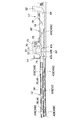
- FIG. 6 is a side view showing the rear portion of the sunshade device 10 in the housed state
- FIG. 7 is a sectional view taken along line VII-VII in FIG.
- the guide frame 12 is integrally formed on the inner side in the vehicle width direction of the frame base 51, which is fixed to the roof outer plate 2, and opens inward.
- a guide rail 53 having a U-shaped cross section for defining the guide groove 52.
- the guide rail 53 defines an inner guide groove 52A having a relatively large vertical dimension inside the vehicle width direction, and defines an outer guide groove 52B having a relatively small vertical dimension outside the vehicle width direction.
- a cable guide portion 55 is provided that defines a cable insertion hole 54 for the push-pull cable 23 above the guide groove 52.
- the cable insertion hole 54 opens inward, and a cable guide rail 57 that defines an inward cable guide groove 56 above the guide groove 52 is formed in the frame base on the inner side of the cable insertion hole 54.
- 51 is provided integrally.
- the guide frame 12 has a certain cross-sectional shape, and can be constituted by an extruded product such as an aluminum alloy.
- the front slider 30 (hereinafter referred to as the first front slider 30 ⁇ / b> A) of the foremost board 11 has an extended portion 33 that extends forward and then extends upward. It is integrally formed.
- a cable holder 34 that holds the front end of the push-pull cable 23 is coupled to the extended portion 33.
- a portion connecting the cable holder 34 and the extending portion 33 is a cable slider 35 slidably held by a cable guide rail 57.
- the first front slider 30A is received in the inner guide groove 52A and guided by the guide rail 53, protrudes outward from the first front slider base 31A, and is received in the outer guide groove 52B.
- the first front slider end portion 32 ⁇ / b> A is guided by the guide rail 53.
- the first front slider end portion 32 ⁇ / b> A has a substantially parallelogram side view shape having a front surface and a rear surface inclined rearward toward the upper side.
- the front slider 30 (hereinafter referred to as the second front slider 30B) of the board 11 from the second to the rear from the front also has an inner guide groove similar to the first front slider 30A. It has a second front slider base 31B received in 52A and a second front slider end 32B received in the outer guide groove 52B.
- the shape of the second front slider end portion 32B is different from that of the first front slider end portion 32A.
- the second front slider end portion 32B has a shape corresponding to the front upper portion of the first front slider end portion 32A having a front surface inclined rearwardly upward, and has a height lower than that of the first front slider end portion 32A. It is said.
- the rear surface of the second front slider end portion 32B is substantially vertical, and an engagement recess 36 is formed on the lower surface of the second front slider end portion 32B.
- the engaging recess 36 has a substantially vertical front surface and an inclined rear surface inclined forward toward the upper side.
- the lower part of the front surface of the engagement recess 36 is an inclined front surface 36a that is inclined forward and downward.
- the inclined front surface 36a is parallel to the front surface of the second front slider end portion 32B.
- the front board 11 housed in the lower part is formed in the portion where the inclined front surface 36 a of the second front slider end 32 B of the rear board 11 housed in the upper part is formed.
- the upper part of the second front slider end 32B enters. Thereby, even if the vertical dimension of the second front slider end portion 32B is larger than the thickness of the board 11, the vertical dimension occupied by one of the second front slider end portions 32B that overlaps vertically in the stored state is reduced, and in the stored state.
- the rear slider 40 (hereinafter referred to as the first rear slider 40A) of the rearmost board 11 is the rear slider 40 (hereinafter referred to as the first slider) of the board 11 from the second to the forefront. 2) and the same shape as the rear slider 40B.
- the rear sliders 40 of all the boards 11 project rearward from the rear slider base 41 (first rear slider base 41A and second rear slider base 41B) received in the inner guide groove 52A, and from the rear slider base 41 to the outside. It has a rear slider end 42 (first rear slider end 42A and second rear slider end 42B) received in the guide groove 52B.
- the rear slider end portion 42 has a shape corresponding to the rear lower portion of the first front slider end portion 32A having a rear surface inclined rearwardly upward, and has a lower height than the first front slider end portion 32A. Yes.
- the front surface of the rear slider end portion 42 is substantially vertical, and an engagement convex portion 46 that forms a complementary shape with the engagement concave portion 36 is formed on the front side of the upper surface of the rear slider end portion 42.
- the engaging convex part 46 has a substantially vertical front surface and an inclined rear surface inclined forward in the upward direction.
- the first rear slider end portion 42A of the rearmost board 11 does not need to have the engaging convex portion 46, and may have the same shape as the first front slider end portion 32A.
- the height occupied by one second front slider end portion 32 ⁇ / b> B in the housed state is equal to or slightly larger than the thickness of the board 11. Further, the height of the rear slider end 42 is equal to or slightly larger than the thickness of the board 11. With these settings, the board 11 is superposed vertically with no gap in the housed state.
- FIG. 8 is a cross-sectional view taken along the line VIII-VIII in FIG. 1, and shows a rear cross-section of the sunshade device 10 in the unfolded state.
- the guide frame 12 is cut out at the rear inner side, and the receiving frame 60 is attached to the guide frame 12 so as to fit into the cut-out portion.
- the housing frame 60 connects the front board 11 and the rear board 11 by disengaging the second rear slider end part 42B of the front board 11 and the second front slider end part 32B of the rear board 11; This is a member for releasing the connection and accommodating the second front slider end portion 32B which is a part of the second front slider 30B and the rear slider end portion 42 which is a part of the rear slider 40.
- the housing frame 60 defines an outer guide groove 52B so as to extend rearward, is connected to the front portion of the defined outer guide groove 52B, and extends forward from the front portion of the outer guide groove 52B.
- the rear slider accommodating portion 62 is connected to the rear portion of the defined outer guide groove 52B and extends upward from the rear portion of the outer guide groove 52B.
- the arm member 18 of the board holder 17 described above is provided between the front slider accommodating portion 61 and the rear slider accommodating portion 62.
- the housing frame 60 defines an outer guide groove 52B at the front portion to which the front slider housing portion 61 is connected so as to have an upwardly projecting curved portion 63 on the front slider housing portion 61 side.
- the “curved portion 63 protruding upward” means that the outer guide groove 52B extending rearward is refracted or curved upward, then refracted or curved downward, and refracted or curved upward so as to extend backward again. Therefore, it means that the front and back portions have a mountain shape. That is, the curved portion 63 is a portion where both the bottom surface and the ceiling surface of the outer guide groove 52B protrude or dent upward, and the groove is curved, and only one of the bottom surface and the ceiling surface protrudes or ridges. It does not mean a recessed part.
- the curved portion 63 of the outer guide groove 52B includes a front inclined portion 63a that bends upward from the main portion of the outer guide groove 52B that extends substantially horizontally rearward and tilts upward toward the rear, and a front inclined portion. It has a top part 63b bent downward from the part 63a and extending substantially horizontally rearward, and a rear inclined part 63c bent downward from the top part 63b and inclined downward toward the rear.
- the rear inclined portion 63c is connected to the main portion of the outer guide groove 52B extending rearward in a manner of bending upward.
- the length of the ceiling surface of the top portion 63b in the front-rear direction is longer than the length in the front-rear direction of the front slider accommodating portion 61, and the front slider accommodating portion 61 directly extends to the curved portion 63 of the outer guide groove 52B so as to extend upward from the top portion 63b. Connected.
- the housing frame 60 defines an outer guide groove 52 ⁇ / b> B so as to have an inclined portion 64 that is inclined upward, which is the rear slider housing portion 62 side toward the rear behind the curved portion 63.
- the inclined portion 64 forms the rear end portion of the outer guide groove 52B, and the rear slider accommodating portion 62 is directly connected to the rear end of the inclined portion 64 and extends upward from the rear end of the inclined portion 64.
- the inclined portion 64 of the outer guide groove 52B is bent upward from the main portion of the outer guide groove 52B extending rearward and is inclined upward and bent rearward in parallel with the front inclined portion 63a. And connected to the rear slider accommodating portion 62.
- the inclined portion 64 may be curved so that the main portion of the outer guide groove 52B extending rearward and the rear slider accommodating portion 62 are smoothly connected.
- the connecting portion of the outer guide groove 52B with the front slider accommodating portion 61 is a portion for guiding the slide of the second front slider end portion 32B and also a portion for accommodating the second front slider end portion 32B.
- the engaging convex portion 46 of the front board 11 engages / disengages with respect to the engaging concave portion 36 of the rear board 11, and the developed state
- the two boards 11 lined up and down are connected and disconnected from each other. That is, the engagement recess 36 which is an engaged portion provided integrally with the second front slider 30B of the rear board 11 and the engagement portion provided integrally with the second rear slider 40B of the front board 11 are provided.
- a coupling mechanism is configured by a certain engaging convex portion 46 and the curved portion 63 (more precisely, the rear inclined portion 63c) of the outer guide groove 52B.
- the front inclined portion 63a of the bending portion 63 does not constitute a coupling mechanism, and is provided to prevent the front portions of the boards 11 that are vertically stacked in the storage state from slidingly contacting each other.
- the front lower portion of the engaging position 36 of the second front slider end portion 32 ⁇ / b> B is the inclined front surface 36 a, so that the front board 11 at the lowermost position of the storage position is the front side.
- the front part of the rear board 11 stored upward at the initial stage of sliding to the upper side is pushed upward, but the second front slider end 32B of the front board 11 overlaps the second front of the rear board 11 that overlaps the upper part.
- the rear board 11 When sliding forward from the slider end 32B, the rear board 11 comes down, and the clearance between the boards 11 can be reduced again.
- the front inclined portion 63a is provided in front of the top portion 63b that forms the connection portion between the outer guide groove 52B and the front slider accommodating portion 61, the rear board 11 that has started to move forward is first (2)
- the front slider end portion 32B descends the front inclined portion 63a.
- the front part of the rear board 11 and the front part of the rear board 11 at the lowermost position of the storage position may come into sliding contact. Absent.
- the first front slider end portion 32A of the frontmost board 11 does not pass through the bending portion 63 because the cable holder 34 is coupled as described with reference to FIGS. . Accordingly, the storage position of the first front slider end portion 32A is in front of the curved portion 63 of the outer guide groove 52B as shown in FIG. Further, since the foremost board 11 has the same dimensions as the other boards 11, the accommodation position of the first rear slider end portion 42A of the forefront board 11 is also the connection between the rear slider accommodation part 62 and the outer guide groove 52B. It becomes more forward than the part.
- the rear end of the main portion of the outer guide groove 52B (the front end of the curved portion 63 and the front end of the inclined portion 64) is the first front slider end portion 32A and the first rear slider end portion 42A of the frontmost board 11. It is in the storage position.
- the inclined portion 64 of the outer guide groove 52B is provided in order to prevent the rear portions of the boards 11 that are vertically stacked in the housed state from slidingly contacting each other. That is, the rear slider end portion 42 (42A, 42B) of the board 11 from the second to the rearmost from the front is accommodated in the rear slider accommodating portion 62 so as to overlap vertically when the board 11 is in the accommodating position. When the foremost board 11 starts sliding forward, the rear slider end 42 of the board 11 moves obliquely downward. Thereby, when the front board 11 slides under the back board 11, the sliding contact of the rear parts of the board 11 is suppressed. Further, the inclined portion 64 also functions as a cam groove for pushing up the rear slider end portion 42 accommodated in the lower portion of the rear slider accommodating portion 62 during the opening operation for accommodating the board 11.
- the front slider accommodating portion 61 and the rear slider accommodating portion 62 are inclined slightly rearward from the outer guide groove 52B upward. This is because the board 11 has an overlapping portion 11a at the front end, and does not overlap in the vertical direction if it is stacked without any gap in the vertical direction. When the board 11 does not have the overlapping portion 11a, the front slider accommodating portion 61 and the rear slider accommodating portion 62 may extend vertically upward.
- the front slider accommodating portion 61 and the rear slider accommodating portion 62 extend in parallel to each other. Therefore, it becomes possible for the second front slider end portion 32 ⁇ / b> B and the rear slider end portion 42 to have the same length in the front-rear direction of the board 11 accommodated in the front slider accommodating portion 61 and the rear slider accommodating portion 62. Is easy to manufacture and assemble.
- the lower front slider end portion 32 ⁇ / b> B which is the lowermost of the second front slider end portions 32 ⁇ / b> B in the storage position, is formed in a portion defining the front slider storage portion 61 of the storage frame 60.
- a restricting device 70 is provided that restricts the forward movement of the second front slider end 32B at the top 63b of the outer guide groove 52B.
- the regulating device 70 includes a plate-like guide member 71 attached to the housing frame 60, a movable member 72 provided so as to be movable in the vertical direction along the guide member 71, and a biasing member that biases the movable member 72 downward. 73.
- the movable member 72 includes a restricting portion 74 that protrudes downward on the front side and a drive portion 75 that protrudes downward on the rear side.
- the urging member 73 is constituted by a torsion coil spring attached to a shaft portion formed on the housing frame 60. One end of the urging member 73 is held by the housing frame 60, and the other end of the urging member 73 abuts on the upper surface of the movable member 72 to urge the movable member 72 downward.
- the restricting portion 74 retreats upward from the protruding position (the state shown in FIG. 8) protruding into the outer guide groove 52B at the front end of the top portion 63b and the outer guide groove 52B. It moves up and down between the retracted positions (the state shown in FIG. 10D).
- the lower surface of the restricting portion 74 faces the front inclined portion 63a when in the protruding position.
- the drive unit 75 retreats from the outer guide groove 52B to the protruding position (the state shown in FIG. 8) that protrudes to the outer guide groove 52B at the rear end of the top 63b. It moves up and down between the retracted positions (the states shown in FIGS. 9C and 10D).
- the lower surface of the drive unit 75 faces the rear inclined portion 63c when it is in the protruding position.
- FIGS. 9 and 10 are side views showing the rear portion of the sunshade device 10 corresponding to FIG. 6 in order to explain the operating procedure of the sunshade device 10.
- 9 and 10 only the fourth board 11 from the front from the frontmost board 11 is shown.
- the state shown in FIG. 9 (A) is changed to the state shown in FIG. 10 (F) in order, and at the time of opening operation for storing the board 11 in the expansion state, In FIG. 10 (F), the state transitions sequentially to the state shown in FIG. 9 (A).
- FIG. 9A shows a state where all the boards 11 are in the storage position.
- the second front slider end 32B of the second to fourth boards 11 from the front is housed in the lower part of the front slider housing 61, and the second rear slider end 42B of the second to fourth boards 11 from the front is
- the lower slider 62 is accommodated in the lower part of the rear slider accommodating part 62. All the boards 11 are arranged in parallel with the guide frame 12.
- the second front slider end portion 32B of the second board 11 from the front before the second front slider end portion 32B is arranged in the forefront among the boards 11 accommodated in the front slider accommodating portion 61 includes the outer guide groove 52B and the front slider. It is in the connection part with the accommodating part 61.
- the restricting portion 74 since the restricting portion 74 is in the protruding position where it protrudes into the outer guide groove 52B, the forward movement of the second board 11 from the front is restricted.
- the rearward movement of the second board 11 from the front can also be restricted by the presence of the drive unit 75 behind the second front slider end 32B, but the second rear slider end 42B is accommodated in the rear slider. It is regulated by being accommodated in the part 62.
- the foremost board 11 When the foremost board 11 is driven forward from this state, as shown in FIG. 9B, the foremost board 11 has the first front slider end portion 32A and the second rear slider end portion 42B. While being guided by the main portion of the outer guide groove 52B, it slides forward while being parallel to the guide frame 12, and the second rear slider end portion 42B reaches the rear end (front end of the main portion) of the curved portion 63. .
- the foremost board 11 When the foremost board 11 is further driven forward, as shown in FIG. 9C, the second rear slider end portion 42B of the forefront board 11 rises the rear inclined portion 63c, and the drive unit 75 is pushed upward to drive the restricting portion 74 to the retracted position and engage with the second front slider end portion 32B of the second board 11 from the front. More specifically, the vertical front wall of the engaging convex portion 46 of the foremost board 11 shown in FIG. 6 engages with the vertical front wall of the engaging concave portion 36 of the second board 11 from the front. . In this state, the frontmost board 11 is in a state where the rear portion is lifted upward and is inclined with respect to the guide frame 12.
- the second rear slider end portion 42B of the forefront board 11 and the second front of the second board 11 from the front are provided.
- the slider end 32B is united with the top 63b to move forward.
- the restricting portion 74 cannot move downward and remains at the retracted position.
- the second rear slider end portion 42B descends the inclined portion 64 of the outer guide groove 52B, the front portion is lifted upward and inclined with respect to the guide frame 12.
- the second rear slider end portion 42B of the frontmost board 11 and the second board 11 from the front are integrated.
- the second front slider end portion 32B moves down the front inclined portion 63a and moves to the front end (rear end of the main portion) of the bending portion 63.
- the frontmost board 11 and the second board 11 from the front are again in parallel with the guide frame 12.
- the restricting portion 74 moves to the lower protruding position. As a result, the forward movement of the second front slider end 32B of the third board 11 from the front is restricted.
- FIG. 10F when the foremost board 11 is driven forward, as shown in FIG. 10F, the second board 11 from the front moves the second front slider end portion 32B and the second rear slider end portion 42B.
- FIG. 9 (FIG. 9) in which the second rear slider end portion 42B reaches the rear end (front end of the main portion) of the curved portion 63 while sliding forward while being guided by the main portion of the outer guide groove 52B. A state corresponding to B) is obtained.
- the second rear slider end portion 42B of the frontmost board 11 and the second board 11 from the front are integrated.
- the second front slider end portion 32B moves up the front inclined portion 63a and reaches the rear end (front end of the top portion 63b) of the front inclined portion 63a while pushing up the restricting portion 74 and moving it to the retracted position.
- the driving unit 75 that moves up and down in synchronization with the regulating unit 74 is also retracted from the outer guide groove 52B.
- the second rear slider end portion 42B of the second board 11 from the front is located at the rear end of the main portion of the outer guide groove 52B (the front end of the inclined portion 64).
- the second rear slider end portion 42B of the frontmost board 11 and the second front slider end portion 32B of the second board 11 from the front are the top portions 63b.
- the driving unit 75 and the regulating unit 74 cannot move downward and remain in the retracted position.
- the second board 11 from the front has the second rear slider end part 42B ascends the inclined part 64 and reaches the lower end of the rear slider accommodating part 62, so that the second and subsequent boards 11 from the front to the second rear side.
- the slider end portion 42B is pushed upward in the rear slider accommodating portion 62 and cannot slide any further.
- the sunshade device 10 is slidably provided to open and close the inner opening 4, and overlaps with each other in the vertical direction behind the inner opening 4 to form the inner opening 4.
- the board 11 includes a plurality of boards 11 that can be in an open storage state and an unfolded state in which the inner opening 4 is closed in the front-rear direction.
- an engagement recess 36 is provided in the front portion of the rear board 11 among the boards 11 arranged in the front-rear direction in the unfolded state, and the front of the boards 11 lined up in the front-back direction in the unfolded state.
- the rear portion of the board 11 engages with the engagement recess 36 of the rear board 11 during the closing operation for shifting from the retracted state to the expanded state, while the rear board 11 is engaged during the opening operation for shifting from the expanded state to the retracted state.
- An engagement convex portion 46 that is disengaged from the engagement concave portion 36 is provided.
- a front slider 30 having a front slider end portion 32 is provided at the front portion of each board 11, and a rear slider 40 having a rear slider end portion 42 is provided at the rear portion of each board 11. 7 and 8, the sunshade device 10 extends in the front-rear direction, and is connected to a guide groove 52 that guides the front slider 30 and the rear slider 40, and an outer guide groove 52B of the guide groove 52.
- the plurality of front slider end portions 32 are connected to the front slider accommodating portion 61 and the outer guide groove 52B so as to overlap each other in the vertical direction.
- a rear slider accommodating portion 62 that accommodates them so as to overlap each other.
- the outer guide groove 52 ⁇ / b> B has a projecting curved portion 63 on the front slider housing portion 61 side at the connection portion with the front slider housing portion 61.
- the front board 11 or its front slider end 32 and rear slider end 42 may be in contact with the rear board 11 or its front slider end 32 and rear slider end 42. Therefore, the clearance between the upper and lower boards 11 is smaller than the clearance at the time of sliding, and the height of the board 11 in the stored state is reduced. Accordingly, the sunshade device 10 can reduce the height of the board 11 in the housed state while suppressing sliding contact between the boards 11.
- the outer guide groove 52 ⁇ / b> B of the present embodiment has an inclined portion 64 that is inclined toward the rear slider accommodating portion 62 toward the rear side behind the curved portion 63. Therefore, when the board 11 moves forward, the rear slider end portion 42 passes through the inclined portion 64 of the outer guide groove 52B (FIGS. 9C to 10D), so A clearance is formed between the rear part of the board 11 and the rear part of the rear board 11 in the storage position. On the other hand, when the board 11 moves rearward, the rear slider end portion 42 passes through the inclined portion 64 of the outer guide groove 52B (FIGS. 10D to 9C), and moves forward. The rear part of the board 11 reduces the clearance with the rear part of the rear board 11 in the storage position. Thus, the structure which makes small the height of the board 11 of a accommodated state is easily implement
- the front slider accommodating portion 61 of the present embodiment extends upward from the top portion 63 b of the curved portion 63. Therefore, when the front board 11 slides in a state where it overlaps with the rear board 11 (FIGS. 9A to 9B and FIGS. 10E to 10F), the clearance becomes the largest. Sliding contact is suppressed.
- the rear slider accommodating portion 62 of this embodiment extends upward from the rear end of the inclined portion 64. For this reason, the clearance between the rear portions of the boards 11 that overlap vertically is increased from the moment when the front board 11 that overlaps the rear board 11 moves forward from the housed position shown in FIG. 10 (D)).
- the rear slider end portion 42 of the front board 11 moves rearward along the inclined portion 64 of the outer guide groove 52B (FIGS. 10D to 9C). ))
- FIGS. 9 (A) to 9 (B) and FIGS. 10 (E) to 10 (F) when the front board 11 is moving in a position where it overlaps the rear board 11, the rear board 11 in the storage position In the board 11, the rear slider end portion 42 is restricted from moving rearward by the rear slider accommodating portion 62, and does not move rearward.
- the rear board 11 in the storage position can move forward if the rear slider end portion 42 is not restricted from moving forward.
- FIGS. 9 (A) to 9 (B) and FIGS. 10 (E) to 10 (F) when the front board 11 is moving in a position where it overlaps the rear board 11, the rear board 11 in the storage position In the board 11, the rear slider end portion 42 is restricted from moving rearward by the rear slider accommodating portion 62, and does not move rearward.
- the rear board 11 in the storage position can move forward if the rear slider end portion 42 is not restricted from moving forward.
- the sunshade device 10 has a protruding position and an outer guide groove that protrude into the outer guide groove 52 ⁇ / b> B in front of the connection portion of the curved portion 63 with the front slider accommodating portion 61.
- the restricting portion 74 moves the rear board. 9 is required to be in the projecting position in order to restrict the forward movement of the board 11, but the engaging convex part 46 of the front board 11 moving forward is engaged with the engaging concave part 36 of the rear board 11.
- the restricting portion 74 needs to be positioned at the retracted position in order to cancel the movement restriction. In this embodiment, as shown in FIGS.
- the sunshade device 10 includes a biasing member 73 that biases the restricting portion 74 toward the protruding position, and a rear slider end portion 42 that slides forward is a curved portion.
- a drive unit 75 that is driven by the slider end 42 to move the restricting unit 74 to the retracted position side when the vehicle passes over 63 is further provided. Therefore, the drive unit 75 using the operation of the rear slider end 42 that slides forward can move the restricting unit 74 to the retracted position with a simple configuration without requiring an additional drive source.
- the engagement recess 36 is provided on the lower surface of the front slider end portion 32, and the engagement protrusion 46 is provided on the upper surface of the rear slider end portion 42.
- the front slider end portion 32 and the rear slider end portion 42 are integrally received in the outer guide groove 52B. Therefore, the component configuration is simplified. Further, since the front slider end portion 32 and the rear slider end portion 42 engaged with each other are integrally received in the outer guide groove 52B, it is possible to suppress the release of the engagement of both due to an impact or the like.
- a drive source 20 is provided for driving the board 11 in the front-rear direction via a push-pull cable 23 coupled to the board 11 provided in the foremost position in the unfolded state.
- the sunshade apparatus 10 is motorized with a simple configuration.
- the sunshade device 10 is applied to the roof of the vehicle 1, but it can also be applied to roofs other than the vehicle 1, walls, and the like.
- the some board 11 may take the accommodation state which overlaps up and down in the vehicle rear of the inner opening 4, you may take the accommodation state in the vehicle front.
- the board 11 stored first at the time of opening operation is positioned above, and the board 11 stored later overlaps below the board 11 at the storage position. It may be.
- the front slider accommodating portion 61 and the rear slider accommodating portion 62 may be configured to extend downward from the outer guide groove 52B, and the curved portion 63 protrudes downward.
- the specific configuration, arrangement, quantity, angle, and the like of each member and part can be changed as appropriate without departing from the spirit of the present invention.
- not all the constituent elements shown in the above embodiment are necessarily essential, and can be appropriately selected.
- Sunshade device 11 Board 30 Front slider 30A First front slider (frontmost board) 30B Second front slider (second to last board from the front) 32A First front slider end (frontmost board) 32B Second front slider end (second to last board from front) 36 Engaging recess (engaged part) 40 Rear slider 40A First rear slider (last board) 40B 2nd rear slider (board 2nd to front) 42A First rear slider end (the last board) 42B Second rear slider end (second board from the back to the foremost board) 46 Engagement convex part (engagement part) 52 guide groove 52B outer guide groove 61 front slider accommodating portion 62 rear slider accommodating portion 63 curved portion 63b top portion 64 inclined portion 72 movable member 73 biasing member 74 regulating portion (regulating member) 75 Drive unit (drive member)
Landscapes
- Engineering & Computer Science (AREA)
- Mechanical Engineering (AREA)
- Fittings On The Vehicle Exterior For Carrying Loads, And Devices For Holding Or Mounting Articles (AREA)
- Curtains And Furnishings For Windows Or Doors (AREA)
Abstract
L'invention concerne un dispositif pare-soleil, dans lequel le contact glissant entre des panneaux est supprimé et la hauteur des panneaux dans un état rentré est réduite. Parmi les panneaux (11) disposés dans une relation avant-arrière dans un état déployé, un panneau arrière (11) présente un évidement de mise en prise (36) situé dans la partie avant du panneau arrière (11), et un panneau avant (11) présente une protubérance de mise en prise (46) située dans la partie arrière du panneau avant (11). Une section contenant un coulisseau avant (61) et une section contenant un coulisseau arrière (62) sont reliées à une rainure de guidage extérieure (52B) pour guider l'extrémité du coulisseau avant (32) et l'extrémité du coulisseau arrière (42) de chacun des panneaux (11). La section de la rainure de guidage extérieure (52B), à laquelle est reliée la section contenant un coulisseau avant (61), comprend une section incurvée (63) qui fait saillie en direction de la section contenant un coulisseau avant (61). Ainsi, lorsque le panneau avant (11) coulisse à travers la position où le panneau avant (11) chevauche le panneau arrière (11), un dégagement est formé entre les panneaux pour éviter un contact glissant entre les panneaux (11) et, dans un état rentré, le dégagement entre les panneaux est réduit afin de diminuer la hauteur des panneaux rentrés.
Priority Applications (1)
| Application Number | Priority Date | Filing Date | Title |
|---|---|---|---|
| JP2017561554A JP6491766B2 (ja) | 2016-01-14 | 2016-12-14 | サンシェード装置 |
Applications Claiming Priority (2)
| Application Number | Priority Date | Filing Date | Title |
|---|---|---|---|
| JP2016005588 | 2016-01-14 | ||
| JP2016-005588 | 2016-01-14 |
Publications (1)
| Publication Number | Publication Date |
|---|---|
| WO2017122487A1 true WO2017122487A1 (fr) | 2017-07-20 |
Family
ID=59312112
Family Applications (1)
| Application Number | Title | Priority Date | Filing Date |
|---|---|---|---|
| PCT/JP2016/087314 Ceased WO2017122487A1 (fr) | 2016-01-14 | 2016-12-14 | Dispositif pare-soleil |
Country Status (2)
| Country | Link |
|---|---|
| JP (1) | JP6491766B2 (fr) |
| WO (1) | WO2017122487A1 (fr) |
Cited By (1)
| Publication number | Priority date | Publication date | Assignee | Title |
|---|---|---|---|---|
| JP7219835B1 (ja) | 2022-03-28 | 2023-02-08 | 八千代工業株式会社 | 車両のルーフモジュール |
Citations (3)
| Publication number | Priority date | Publication date | Assignee | Title |
|---|---|---|---|---|
| JPS62149422U (fr) * | 1986-03-14 | 1987-09-21 | ||
| JPH0328918U (fr) * | 1989-07-31 | 1991-03-22 | ||
| JP2008006983A (ja) * | 2006-06-29 | 2008-01-17 | Yachiyo Industry Co Ltd | 車両のサンシェード装置 |
-
2016
- 2016-12-14 JP JP2017561554A patent/JP6491766B2/ja active Active
- 2016-12-14 WO PCT/JP2016/087314 patent/WO2017122487A1/fr not_active Ceased
Patent Citations (3)
| Publication number | Priority date | Publication date | Assignee | Title |
|---|---|---|---|---|
| JPS62149422U (fr) * | 1986-03-14 | 1987-09-21 | ||
| JPH0328918U (fr) * | 1989-07-31 | 1991-03-22 | ||
| JP2008006983A (ja) * | 2006-06-29 | 2008-01-17 | Yachiyo Industry Co Ltd | 車両のサンシェード装置 |
Cited By (4)
| Publication number | Priority date | Publication date | Assignee | Title |
|---|---|---|---|---|
| JP7219835B1 (ja) | 2022-03-28 | 2023-02-08 | 八千代工業株式会社 | 車両のルーフモジュール |
| WO2023188783A1 (fr) * | 2022-03-28 | 2023-10-05 | 八千代工業株式会社 | Module de toit de véhicule |
| JP2023144279A (ja) * | 2022-03-28 | 2023-10-11 | 八千代工業株式会社 | 車両のルーフモジュール |
| US12502939B2 (en) | 2022-03-28 | 2025-12-23 | Yachiyo Industry Co., Ltd. | Roof module for vehicle |
Also Published As
| Publication number | Publication date |
|---|---|
| JP6491766B2 (ja) | 2019-03-27 |
| JPWO2017122487A1 (ja) | 2018-09-13 |
Similar Documents
| Publication | Publication Date | Title |
|---|---|---|
| CN102205856B (zh) | 车辆的行李舱盖装置 | |
| JP5168114B2 (ja) | 車両用サンシェード装置 | |
| EP1813475B1 (fr) | Dispositif de recouvrement | |
| JP5040373B2 (ja) | 車両用サンシェード装置 | |
| JP6491766B2 (ja) | サンシェード装置 | |
| JP2014234017A (ja) | ロールシェード装置 | |
| JP4747814B2 (ja) | サンシェードパネル装置 | |
| JP4826381B2 (ja) | 車両のトノカバー装置 | |
| JP5060538B2 (ja) | サンシェード装置 | |
| JP2014234018A (ja) | ロールシェード装置 | |
| JP4796838B2 (ja) | 車両のサンシェード装置 | |
| JP2010201956A (ja) | 自動車用サンシェード装置 | |
| JP4250178B2 (ja) | 多板サンシェード装置 | |
| JP4203515B2 (ja) | 車両のサンシェード装置 | |
| JP4574539B2 (ja) | 多板サンシェード装置 | |
| JP4246759B2 (ja) | 多板サンシェード装置 | |
| JP2011079448A (ja) | サンシェード装置 | |
| JP2009083644A (ja) | サンシェード装置 | |
| JP2006044637A (ja) | 車両用サンシェード装置 | |
| JP2007302034A (ja) | シェード装置 | |
| JP2006168575A (ja) | 車両用サンシェード装置 | |
| JP4581840B2 (ja) | 車両用サンシェード装置 | |
| JP2009083633A (ja) | サンシェード装置 | |
| JP4840123B2 (ja) | サンバイザ装置 | |
| JP2007283924A (ja) | 車両のトノカバー装置 |
Legal Events
| Date | Code | Title | Description |
|---|---|---|---|
| 121 | Ep: the epo has been informed by wipo that ep was designated in this application |
Ref document number: 16885089 Country of ref document: EP Kind code of ref document: A1 |
|
| ENP | Entry into the national phase |
Ref document number: 2017561554 Country of ref document: JP Kind code of ref document: A |
|
| NENP | Non-entry into the national phase |
Ref country code: DE |
|
| 122 | Ep: pct application non-entry in european phase |
Ref document number: 16885089 Country of ref document: EP Kind code of ref document: A1 |