WO2017122558A1 - 便座便蓋装置 - Google Patents
便座便蓋装置 Download PDFInfo
- Publication number
- WO2017122558A1 WO2017122558A1 PCT/JP2017/000037 JP2017000037W WO2017122558A1 WO 2017122558 A1 WO2017122558 A1 WO 2017122558A1 JP 2017000037 W JP2017000037 W JP 2017000037W WO 2017122558 A1 WO2017122558 A1 WO 2017122558A1
- Authority
- WO
- WIPO (PCT)
- Prior art keywords
- toilet
- toilet seat
- toilet lid
- lid
- seat
- Prior art date
- Legal status (The legal status is an assumption and is not a legal conclusion. Google has not performed a legal analysis and makes no representation as to the accuracy of the status listed.)
- Ceased
Links
Images



Classifications
-
- A—HUMAN NECESSITIES
- A47—FURNITURE; DOMESTIC ARTICLES OR APPLIANCES; COFFEE MILLS; SPICE MILLS; SUCTION CLEANERS IN GENERAL
- A47K—SANITARY EQUIPMENT; ACCESSORIES THEREFOR, e.g. TOILET ACCESSORIES
- A47K13/00—Seats or covers for all kinds of closets
-
- A—HUMAN NECESSITIES
- A47—FURNITURE; DOMESTIC ARTICLES OR APPLIANCES; COFFEE MILLS; SPICE MILLS; SUCTION CLEANERS IN GENERAL
- A47K—SANITARY EQUIPMENT; ACCESSORIES THEREFOR, e.g. TOILET ACCESSORIES
- A47K13/00—Seats or covers for all kinds of closets
- A47K13/10—Devices for raising and lowering ; Collapsible or rotating seats or covers
-
- A—HUMAN NECESSITIES
- A47—FURNITURE; DOMESTIC ARTICLES OR APPLIANCES; COFFEE MILLS; SPICE MILLS; SUCTION CLEANERS IN GENERAL
- A47K—SANITARY EQUIPMENT; ACCESSORIES THEREFOR, e.g. TOILET ACCESSORIES
- A47K13/00—Seats or covers for all kinds of closets
- A47K13/12—Hinges
Definitions
- the present invention relates to a toilet seat toilet lid device.
- This application claims priority based on Japanese Patent Application No. 2016-006411 filed on Jan. 15, 2016, the contents of which are incorporated herein by reference.
- a flush toilet has a main body portion installed on a toilet bowl, and a toilet seat and a toilet lid provided so as to be rotatable with respect to the main body portion (Patent Documents below) 1).
- the toilet seat and toilet lid are electrically opened and closed by a single unit equipped with a toilet seat opening and closing motor and a toilet lid opening and closing motor. Both the toilet seat opening and closing motor and the toilet lid opening and closing motor are provided in both units.
- a single pivot shaft is connected and a toilet seat and a toilet lid are pivotally supported by the pivot shaft is known.
- a toilet seat or toilet lid opening / closing motor is selectively driven to open and close the toilet seat or toilet lid.
- a toilet seat opening / closing motor is provided in one unit
- a toilet lid opening / closing motor is provided in another unit
- a toilet seat pivot shaft and a toilet lid opening / closing shaft connected to the toilet seat opening / closing motor are provided.
- the pivot axis of the toilet lid connected to the motor is provided separately.
- the pivot axis of the toilet lid is arranged behind the pivot axis of the toilet seat.
- the toilet seat opening / closing motor and the toilet lid opening / closing motor are collectively provided in one unit, and therefore the size of the unit increases. There is a point.
- the toilet lid extends to the rear side (opposite to the seated person of the flush toilet), so the toilet lid There is a problem that the length in the front-rear direction increases and the toilet lid becomes larger.
- the present invention has been made in view of the above circumstances, and provides a toilet seat toilet lid device that can be made compact.
- a toilet seat toilet lid device includes a toilet seat and a toilet lid, a toilet seat driving device, a toilet seat rotating shaft, a toilet lid driving device, a toilet lid rotating shaft, Is provided.
- the toilet seat and the toilet lid are provided to be rotatable between a standing state and a lying state with respect to the toilet.
- the toilet seat drive device rotates the toilet seat.
- the toilet seat rotation shaft extends from the toilet seat drive device to one side in the width direction of the toilet bowl, and supports the toilet seat in a rotatable manner and supports the toilet lid.
- the toilet lid driving device rotates the toilet lid.
- the toilet lid rotating shaft extends from the toilet lid driving device to the other side in the width direction of the toilet bowl, and supports the toilet lid rotatably and supports the toilet seat.
- the toilet seat rotation axis and the toilet lid rotation axis are arranged on the same axis along the width direction of the toilet.
- the toilet seat rotating shaft that rotatably supports the toilet seat and the toilet lid rotating shaft that rotatably supports the toilet lid are arranged on the same axis along the width direction of the toilet bowl. ing. Therefore, the length and height in the horizontal direction orthogonal to the width direction of the toilet bowl can be suppressed, rather than the toilet seat rotation axis and the toilet lid rotation axis being arranged offset from the axis. Further, for example, when the toilet seat driving device for rotating the toilet seat rotation shaft and the toilet lid driving device for rotating the toilet lid rotation shaft are arranged in a distributed manner, the toilet seat toilet lid can be installed rather than collectively installed in one place. It can be set as the structure which suppressed the magnitude
- the toilet seat is formed with a toilet seat side fitting hole in which the toilet seat rotation shaft is disposed and a toilet seat side support hole in which the toilet lid rotation shaft is disposed.
- the toilet lid is formed with a toilet lid side support hole in which the toilet seat rotation shaft is disposed and a toilet lid side fitting hole in which the toilet lid rotation shaft is disposed.
- the toilet seat rotating shaft is fitted and arranged in the toilet seat side fitting hole so as to be able to rotate together with the toilet seat, and is slidably arranged in the toilet lid side support hole.
- the toilet lid rotation shaft is slidably disposed in the toilet seat side support hole, and is fitted and disposed in the toilet lid side fitting hole so as to be able to rotate together with the toilet lid.
- the toilet seat rotation shaft is fitted and disposed in the toilet seat side fitting hole formed in the toilet seat so that it can rotate together with the toilet seat. Therefore, when the toilet seat rotating shaft rotates, the toilet seat rotates together with the toilet seat rotating shaft.
- the toilet lid rotation shaft is slidably disposed in a toilet seat side support hole formed in the toilet seat. Therefore, the toilet seat slides around the toilet lid rotation axis. Therefore, the toilet seat smoothly rotates between the standing state and the lying state.
- the toilet lid rotation shaft is fitted and disposed in a toilet lid side fitting hole formed in the toilet lid so that it can rotate together with the toilet lid. Therefore, when the toilet lid rotating shaft rotates, the toilet lid rotates together with the toilet lid rotating shaft.
- the toilet seat rotation shaft is slidably disposed in a toilet lid side support hole formed in the toilet lid. Therefore, the toilet lid slides around the toilet seat rotation axis. Accordingly, the toilet lid smoothly rotates between the standing state and the lying state.
- the toilet seat rotating shaft includes an oval toilet seat rotating shaft portion and a perfect circular toilet seat rotating shaft portion.
- the ellipse toilet seat rotating shaft portion is disposed in the toilet seat side fitting hole and is formed in a substantially oval cross section.
- the perfect toilet seat rotation shaft portion is disposed in the toilet lid side support hole and has a perfect circular cross section.
- the toilet lid rotation shaft includes a perfect circular toilet lid rotation shaft portion and an oval toilet lid rotation shaft portion.
- the round toilet lid rotation shaft portion is disposed in the toilet seat side support hole and has a perfect circular cross section.
- the ellipse toilet lid rotation shaft portion is disposed in the toilet lid side fitting hole and has a substantially oval cross section.
- the toilet seat side fitting hole is formed in a substantially oval cross section corresponding to the shape of the oval toilet seat rotating shaft portion.
- the toilet seat side support hole is formed in a perfect circular cross section that is slightly larger than the round toilet lid rotation shaft portion. At least a part of the toilet lid side support hole is formed in a perfect circular cross section that is slightly larger than the perfect toilet seat rotation shaft portion. At least a part of the toilet lid side fitting hole is formed in a substantially oval cross section corresponding to the shape of the oval toilet lid rotating shaft portion.
- the ellipse toilet seat pivoting shaft portion of the toilet seat pivoting shaft is fitted into the toilet seat side fitting hole formed in a substantially oval cross section corresponding to the shape of the ellipse toilet seat pivoting shaft portion. Has been placed. Therefore, when the toilet seat rotation shaft rotates, the toilet seat reliably rotates together with the toilet seat rotation shaft. Further, the true toilet seat rotating shaft portion of the toilet lid rotating shaft is slidably disposed in a toilet seat side support hole formed in a perfectly circular cross section slightly larger than the true toilet lid rotating shaft portion. Yes. Therefore, the toilet seat slides reliably around the toilet lid rotation axis.
- the ellipse toilet lid pivoting shaft portion of the toilet lid pivoting shaft has at least a part of the toilet lid side fitting hole formed in a substantially oval cross section corresponding to the shape of the ellipse toilet lid pivoting shaft portion. Are fitted and arranged. Therefore, when the toilet lid rotation shaft rotates, the toilet lid reliably rotates together with the toilet lid rotation shaft.
- the round toilet lid pivoting shaft part of the toilet seat pivoting shaft is slidable in the toilet lid side support hole formed at least partially in a perfect circle shape with a slightly larger cross section than the perfect toilet seat pivoting shaft portion. Is arranged. Therefore, the toilet lid slides reliably around the toilet seat rotation axis.
- FIG. 3 is a cross-sectional view taken along line AA in FIG. 2. It is a perspective view of the toilet seat rotation axis
- FIG. 5 is a cross-sectional view of the vicinity of the toilet lid rotating shaft in a state where the toilet seat and the toilet lid of the toilet seat toilet lid device according to the embodiment of the present invention are closed.
- FIG. 6 is a cross-sectional view of the vicinity of the toilet lid rotation shaft in a state where the toilet seat is closed and the toilet lid is opened according to the embodiment of the present invention.
- FIG. 5 is a cross-sectional view of the vicinity of the toilet seat rotation axis in a state where the toilet seat is closed and the toilet lid is opened in the toilet seat toilet lid device according to the embodiment of the present invention. It is sectional drawing of the toilet seat vicinity axis
- FIG. 6 is a cross-sectional view of the vicinity of the toilet lid rotation shaft in a state where the toilet seat and toilet lid of the toilet seat toilet lid device according to the embodiment of the present invention are opened.
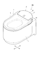
- FIG. 1 is a perspective view of a flush toilet equipped with a toilet seat toilet lid device according to an embodiment of the present invention.
- the flush toilet 100 includes a toilet bowl body (toilet bowl) 1 made of earthenware and a toilet seat unit (toilet seat toilet lid device) 2 installed on the toilet bowl body 1.
- FIG. 2 is a perspective view of the toilet seat unit 2.
- the toilet seat unit 2 has a main body 3 and a toilet lid 7.
- the main body 3 is attached to the upper surface of the rear part of the toilet body 1.
- the toilet lid 7 is provided so as to be rotatable with respect to the main body 3.
- the direction in which the face of the user sitting on the toilet seat 6 faces is the front side
- the direction in which the user seated on the toilet seat 6 faces is the rear side.
- the horizontal direction orthogonal to the front-rear method is the left-right direction (width direction of the flush toilet 100), the right side (one side in the width direction) is the right side when viewed from the user, and the left side (the other side in the width direction) when viewed from the user Side) is the left side.
- the main body 3 includes a toilet seat motor (toilet seat driving device) 31, a toilet seat rotation shaft 40, a toilet lid motor (toilet lid driving device) 32, a toilet lid rotation shaft 50, and a housing portion 33. is doing.
- the toilet seat motor 31 rotates the toilet seat 6.
- the toilet seat rotation shaft 40 is connected to the toilet seat motor 31.
- the toilet lid motor 32 rotates the toilet lid 7.
- the toilet lid rotation shaft 50 is connected to the toilet lid motor 32.
- the casing 33 accommodates the toilet seat motor 31, the toilet seat rotation shaft 40, the toilet lid motor 32, and the toilet lid rotation shaft 50.
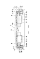
- FIG. 3 is a cross-sectional view taken along the line AA in FIG.
- a support base 34 is fixed with screws 34S on the right side
- a support base 35 is fixed with screws 35S on the left side.
- the support bases 34 and 35 are spaced apart in the left-right direction.
- the toilet seat motor 31 is fixed to the support base 34 by screws (not shown).
- a toilet lid motor 32 is fixed to the support base 35 by screws (not shown).
- the toilet seat motor 31 and the toilet lid motor 32 are provided to be separated from each other in the left-right direction.
- FIG. 4 is a perspective view of the toilet seat rotating shaft 40.
- FIG. 5 is a perspective view of the toilet lid rotation shaft 50.
- the toilet seat rotation shaft 40 includes a proximal end shaft portion 41, a toilet seat fitting shaft portion (oval toilet seat rotation shaft portion) 42, and a toilet lid support shaft portion (round flight). Lid rotation shaft portion) 43.
- the proximal shaft portion 41 is connected to the toilet seat motor 31 and extends to the right side.
- the toilet seat fitting shaft portion 42 extends to the right side continuously to the proximal end shaft portion 41.
- the toilet lid support shaft portion 43 extends to the right side continuously to the toilet seat fitting shaft portion 42.
- the proximal end shaft portion 41 is formed in a circular shape when viewed in cross section.
- the toilet seat fitting shaft portion 42 is formed in a substantially oval shape in cross-sectional view. In the state in which the toilet seat 6 and the toilet lid 7 shown in FIG. 2 are closed, the toilet seat fitting shaft portion 42 has a substantially oval shape that is long in the vertical direction.
- the toilet seat fitting shaft part 42 has a pair of flat surface parts 42A and a curved surface part 42B.
- the pair of flat surface portions 42A are spaced apart from each other (disposed in the front-rear direction in the state shown in FIG. 2) and formed in a planar shape.
- the curved surface portion 42B is formed in a curved shape by connecting the ends of the pair of flat surface portions 42A.
- the toilet lid support shaft portion 43 is formed in a perfect circle shape in cross section.
- the central axis of the toilet lid support shaft portion 43 and the central axis of the toilet seat fitting shaft portion 42 are disposed on the same axis O1 along the left-right direction.
- the toilet lid rotation shaft 50 includes a proximal end shaft portion 51, a toilet seat support shaft portion (round toilet seat rotation shaft portion) 52, and a toilet lid fitting shaft portion (oval).
- a toilet lid rotation shaft portion) 53 As shown in FIGS. 3 and 5, the toilet lid rotation shaft 50 includes a proximal end shaft portion 51, a toilet seat support shaft portion (round toilet seat rotation shaft portion) 52, and a toilet lid fitting shaft portion (oval).
- a toilet lid rotation shaft portion) 53 As shown in FIGS. 3 and 5, the toilet lid rotation shaft 50 includes a proximal end shaft portion 51, a toilet seat support shaft portion (round toilet seat rotation shaft portion) 52, and a toilet lid fitting shaft portion (oval).
- a toilet lid rotation shaft portion) 53 As shown in FIGS. 3 and 5, the toilet lid rotation shaft 50 includes a proximal end shaft portion 51, a toilet seat support shaft portion (round toilet seat rotation shaft portion) 52, and a toilet lid fitting shaft portion (oval).
- a toilet lid rotation shaft portion 53
- the proximal shaft 51 is connected to the toilet lid motor 32 and extends to the left.
- the proximal end shaft portion 51 is formed in a circular shape in sectional view.
- the toilet seat support shaft portion 52 extends to the left continuously from the proximal shaft portion 51.
- the toilet seat support shaft portion 52 is formed in a perfect circle shape in cross section.
- the toilet lid fitting shaft portion 53 extends to the left side continuously to the toilet seat support shaft portion 52.
- the toilet lid fitting shaft portion 53 is formed in a substantially oval shape in cross section. In the state in which the toilet seat 6 and the toilet lid 7 shown in FIG. 2 are closed, the toilet lid fitting shaft portion 53 has a substantially oval shape that is long in the front-rear direction.
- the toilet lid fitting shaft portion 53 has a pair of flat surface portions 53A and a curved surface portion 53B.
- the pair of flat portions 53A are arranged apart from each other (disposed in the vertical direction in the state shown in FIG. 2) and formed in a planar shape.
- the curved surface portion 53B is formed in a curved shape by connecting the ends of the pair of flat surface portions 53A.
- the central axis of the toilet lid fitting shaft part 53 and the central axis of the toilet seat support shaft part 52 are arranged on the same axis O1 along the left-right direction.
- the toilet seat motor 31, the toilet lid motor 32, the toilet seat rotating shaft 40, and the toilet lid rotating shaft 50 are disposed on the same axis O1 along the left-right direction.
- FIG. 6 is a perspective view of the toilet seat 6 as viewed from the left side.
- FIG. 7 is a perspective view of the toilet seat 6 as viewed from the right side.
- the toilet seat 6 is formed in a substantially annular shape in plan view, and shaft support arm portions 60 ⁇ / b> R and 60 ⁇ / b> L extending rearward are provided on both left and right sides of the rear portion of the toilet seat 6. Yes.
- the shaft support arm 60R extends rearward from the right side of the rear part of the toilet seat 6.
- the shaft support arm 60R is formed with a through hole 61R penetrating in the left-right direction.
- the through hole 61R of the shaft support arm 60R is formed by communicating an inner (left) inner hole 62R and an outer (right) outer hole (toilet seat side fitting hole) 63R.
- the inner hole 62R is formed in a circular shape in a cross-sectional view corresponding to the shape of the base end shaft portion 41 (see FIG. 4; the same applies hereinafter) of the toilet seat rotation shaft 40.
- the outer hole 63R is formed in an oval shape in sectional view corresponding to the shape of the toilet seat fitting shaft portion 42 (see FIG. 4; the same applies hereinafter) of the toilet seat rotating shaft 40.
- the outer hole 63R has a substantially oval shape that is long in the vertical direction.
- the outer hole portion 63R is a curved surface formed by connecting a pair of planar portions 63A that are spaced apart from each other in the front-rear direction and formed in a planar shape, and ends of the pair of planar portions 63A. It is formed with the part 63B.
- FIG. 8 is a sectional view of the vicinity of the toilet seat fitting shaft portion 42 of the toilet seat rotating shaft 40 in a state where the toilet seat 6 and the toilet lid 7 are closed.
- the toilet seat fitting shaft portion 42 of the toilet seat rotating shaft 40 is fitted in the outer hole 63R.
- the toilet seat fitting shaft portion 42 is fitted by a pair of flat surface portions 63A and a pair of curved surface portions 63B of the outer hole portion 63R. Thereby, the toilet seat 6 can rotate together with the toilet seat rotating shaft 40.
- the through hole 61L of the shaft support arm 60L is formed by communicating an inner (right) inner hole 62L and an outer (left) outer hole 63L. .
- the inner hole 62L is formed in a circular shape in sectional view corresponding to the shape of the proximal end shaft portion 51 (see FIG. 5; the same applies hereinafter) of the toilet lid rotation shaft 50.
- the outer hole portion (toilet seat side support hole) 63L is formed in a perfect circle shape in sectional view that is slightly larger than the shape of the toilet seat support shaft portion 52 (see FIG. 5; the same applies hereinafter) of the toilet lid rotation shaft 50. .
- the toilet seat support shaft portion 52 of the toilet lid rotation shaft 50 is slidable in the outer hole portion 63L.
- FIG. 9 is a perspective view of the toilet lid 7 as viewed from the lower left.
- FIG. 10 is a perspective view of the toilet lid 7 as viewed from the lower right.
- the toilet lid 7 has an upper surface portion 71 and a side wall portion 72.
- the upper surface portion 71 forms the upper surface.
- the side wall portion 72 hangs downward from the edge portion of the upper surface portion 71.
- rear extension portions 73R and 73L extending rearward are provided on both the left and right sides of the upper surface portion 71.
- shaft support wall portions 74 ⁇ / b> R and 74 ⁇ / b> L extending rearward are also provided at the rear portion of the side wall portion 72.
- bulge portions 75R and 75L swelled toward the opposite shaft support wall portions 74L and 74R, respectively.
- slide portions 76R and 76L that are slidable in the front-rear direction are provided adjacent to the bulging portions 75R and 75L.
- a support hole (a toilet lid side support hole) 80R and a fitting hole (a toilet lid side fitting hole) 80L extending in the left-right direction are formed at the lower ends of the bulging portions 75R and 75L, respectively.
- the upper portion 81A of the support hole 80R is formed in a perfect circle shape in cross section that swells upward.
- the upper portion 81A of the support hole 80R has a perfect circle shape in cross-section, slightly larger than the shape of the toilet lid support shaft portion 43 (see FIG. 4; the same applies hereinafter) of the toilet seat rotation shaft 40.
- the lower portion of the support hole 80R has a shape that is continuous with the upper portion 81A, and is formed by a pair of flat portions 81B that are spaced apart in the front-rear direction and formed in a flat shape.
- the separation distance between the pair of flat portions 81B is slightly longer than the diameter of the toilet lid support shaft portion 43 of the toilet seat rotation shaft 40. Thereby, the toilet lid support shaft portion 43 of the toilet seat rotation shaft 40 is slidable in the support hole 80R.
- the upper portion of the fitting hole 80L has a shape corresponding to the toilet lid fitting shaft portion 53 (see FIG. 5; the same applies hereinafter) of the toilet lid rotating shaft 50.
- the upper portion of the fitting hole 80L is formed by a pair of curved surface portions 81C that are spaced apart in the front-rear direction and formed in a curved shape, and an upper flat surface portion 81D that is formed in a planar shape by connecting the upper portions of the curved surface portions 81C.
- a lower flat surface portion 81 ⁇ / b> E formed in a planar shape is continuously provided below the curved surface portion 81.
- FIG. 11 is a cross-sectional view of the toilet lid rotating shaft 50 and its vicinity in the vicinity of the toilet lid fitting shaft portion 53 when the toilet seat 6 and the toilet lid 7 are closed.
- the toilet lid fitting shaft portion 53 of the toilet lid rotating shaft 50 is fitted in the fitting hole 80L.
- the toilet lid fitting shaft portion 53 is fitted by the upper surfaces of the pair of curved surface portions 81C, the upper flat surface portion 81D, and the slide portion 76L.
- the toilet lid 7 can rotate together with the toilet lid rotation shaft 50.
- the toilet seat rotation shaft 40 and the toilet lid rotation shaft 50 are inserted into the support hole 80R and the fitting hole 80L, respectively.
- the toilet seat pivot shaft 40 and the toilet lid pivot shaft 50 are supported by the toilet lid 7 by sliding the slide portions 76R and 76L rearward to the positions shown in FIGS.
- An operation unit (not shown; the same applies hereinafter) is provided separately from or on the toilet seat unit 2 itself shown in FIG.
- the operation unit is provided with an input unit (not shown; the same applies hereinafter) for opening and closing the toilet seat 6 and the toilet lid 7.
- the toilet seat unit 2 is provided with a control unit (not shown; the same applies hereinafter).
- the control unit When the opening signal and the closing signal of the toilet seat 6 are input from the input unit, the control unit outputs the opening operation signal and the closing operation signal to the toilet seat motor 31 (see FIG. 2, the same applies hereinafter). Further, when the opening signal and the closing signal of the toilet lid 7 are input from the input unit, the control unit outputs the opening operation signal and the closing operation signal to the toilet lid motor 32 (see FIG. 2, the same applies hereinafter).
- the operation of the toilet seat unit 2 will be described.
- the input unit An open signal is output to the control unit.
- the control unit outputs an opening operation signal to the toilet lid motor 32.
- FIG. 12 is a cross-sectional view of the vicinity of the toilet lid rotation shaft 50 when the toilet seat 6 is closed and the toilet lid 7 is opened.
- FIG. 13 is a cross-sectional view of the vicinity of the toilet seat rotating shaft 40 when the toilet seat 6 is closed and the toilet lid 7 is opened.
- the toilet lid motor 32 rotates the toilet lid rotation shaft 50 in the opening direction.
- the toilet lid 7 fitted to the toilet lid fitting shaft portion 53 of the toilet lid turning shaft 50 rotates and opens together with the toilet lid turning shaft 50.
- FIG. 13 on the toilet seat rotation shaft 40 side, the toilet lid 7 supported by the toilet lid support shaft portion 43 of the toilet seat rotation shaft 40 slides around the toilet lid support shaft portion 43. .
- the input unit When the user inputs an operation for opening the toilet seat 6 to the input unit, the input unit outputs an opening signal of the toilet seat 6 to the control unit.
- the control unit outputs an opening operation signal to the toilet seat motor 31.
- FIG. 14 is a cross-sectional view of the vicinity of the toilet seat rotation shaft 40 when the toilet seat 6 and the toilet lid 7 are opened.
- FIG. 15 is a cross-sectional view of the vicinity of the toilet lid rotation shaft 50 when the toilet seat 6 and the toilet lid 7 are opened.
- the input unit In a state where the toilet seat 6 and the toilet lid 7 are opened (standing state), when the user inputs an operation for closing the toilet seat 6 to the input unit, the input unit outputs a closing signal of the toilet seat 6 to the control unit.
- the control unit outputs a closing operation signal to the toilet seat motor 31.
- the toilet seat motor 31 rotates the toilet seat rotating shaft 40 in the closing direction when a closing operation signal is input.
- the toilet seat 6 fitted to the toilet seat fitting shaft portion 42 of the toilet seat turning shaft 40 rotates together with the toilet seat turning shaft 40 and closes.
- the toilet seat 6 supported by the toilet seat support shaft portion 52 of the toilet lid rotation shaft 50 slides around the toilet seat support shaft portion 52.
- the input unit When the user inputs an operation for closing the toilet lid 7 to the input unit, the input unit outputs a closing signal of the toilet lid 7 to the control unit.
- the control unit outputs a closing operation signal to the toilet lid motor 32.
- the toilet lid motor 32 rotates the toilet lid rotation shaft 50 in the closing direction.
- the toilet lid 7 fitted to the toilet lid fitting shaft portion 53 of the toilet lid turning shaft 50 rotates together with the toilet lid turning shaft 50 and closes.
- the toilet lid 7 supported by the toilet lid support shaft portion 43 of the toilet seat pivot shaft 40 slides around the toilet lid support shaft portion 43. .
- the user inputs the operation for closing the toilet lid 7 without inputting the operation for closing the toilet seat 6 so that the toilet seat 6 and the toilet lid 7 are simultaneously closed. It may be.
- the toilet seat pivot shaft 40 that pivotably supports the toilet seat 6 and the toilet lid pivot shaft 50 that pivotally supports the toilet lid 7 are provided on the flush toilet 100. It arrange
- the toilet seat motor 31 that rotates the toilet seat rotation shaft 40 and the toilet lid motor 32 that rotates the toilet lid rotation shaft 50 are arranged apart from each other in the left-right direction,
- the height, width, and the like of the main body portion 3 can be suppressed rather than collectively installing the toilet seat motor and the toilet lid motor. Therefore, the length, height, and size of the flush toilet 100 in the front-rear direction can be suppressed, and the overall configuration can be made compact.
- the toilet seat rotating shaft 40 is fitted and disposed in an outer hole 63R formed in the toilet seat 6, when the toilet seat rotating shaft 40 rotates, the toilet seat 6 rotates together with the toilet seat rotating shaft 40. Move. Further, since the toilet lid rotation shaft 50 is slidably disposed in the outer hole 63L formed in the toilet seat 6, the toilet seat 6 slides around the toilet lid rotation shaft 50. Therefore, the toilet seat 6 smoothly rotates between the standing state and the lying state.
- the toilet lid rotating shaft 50 is fitted and disposed in the fitting hole 80L formed in the toilet lid 7, when the toilet lid rotating shaft 50 rotates, together with the toilet lid rotating shaft 50, The toilet lid 7 rotates. Further, since the toilet seat rotating shaft 40 is slidably disposed in a support hole 80R formed in the toilet lid 7, the toilet lid 7 slides around the toilet seat rotating shaft 40. Accordingly, the toilet lid 7 smoothly rotates between the standing state and the lying state.
- the toilet seat fitting shaft portion 42 of the toilet seat rotating shaft 40 is fitted and disposed in an outer hole 63R formed in a substantially oval cross section corresponding to the shape of the toilet seat fitting shaft portion 42. Therefore, when the toilet seat rotating shaft 40 rotates, the toilet seat 6 rotates reliably together with the toilet seat rotating shaft 40.
- the toilet seat support shaft portion 52 of the toilet lid rotation shaft 50 is slidably disposed in an outer hole portion 63 ⁇ / b> R formed in a perfectly circular cross section slightly larger than the toilet lid support shaft portion 43. Therefore, the toilet seat 6 slides reliably around the toilet lid rotation shaft 50.
- the toilet lid fitting shaft portion 53 of the toilet lid rotating shaft 50 is fitted into a fitting hole 80 ⁇ / b> L formed at least partially in a substantially oval cross section corresponding to the shape of the toilet lid fitting shaft portion 53. Has been placed. Therefore, when the toilet lid rotation shaft 50 rotates, the toilet lid 7 reliably rotates together with the toilet lid rotation shaft 50. Further, the toilet lid support shaft portion 43 of the toilet seat rotation shaft 40 is slidably disposed in a support hole 80 ⁇ / b> R formed at least partially in a perfectly circular cross section slightly larger than the toilet lid support shaft portion 43. Yes. Therefore, the toilet lid 7 slides reliably around the toilet seat rotation axis 40.
- flush toilet 100 is not limited to the above-described embodiment, and can be appropriately changed or replaced without departing from the gist of the present invention.
- Toilet body (toilet) 2 Toilet seat unit (toilet seat toilet lid device) 3 ... Main body 6 ; Toilet seat 7 ... Toilet lid 31 ... Toilet seat motor (toilet seat drive device) 32 ... Toilet lid motor (toilet lid drive device) 33 ... Case 40 ... Toilet seat rotation shaft 41 ... Base end shaft portion 42 ... Toilet seat fitting shaft portion (oval toilet seat rotation shaft portion) 43 ... Toilet lid support shaft (round toilet lid rotation shaft) 50: Toilet lid rotation shaft 51 ... Base end shaft portion 52 ... Toilet seat support shaft portion (round toilet seat rotation shaft portion) 53 ... Toilet lid fitting shaft (oval toilet lid rotation shaft) 60R, 60L ... Shaft support arms 61R, 61L ... Through holes 62R, 62L ...
Landscapes
- Health & Medical Sciences (AREA)
- Public Health (AREA)
- Toilet Supplies (AREA)
Abstract
便座便蓋装置(2)は、便器に対して起立状態と倒伏状態との間を回動可能に設けられる便座(6)及び便蓋(7)と、便座(6)を回動させる便座駆動装置(31)と、便座駆動装置(31)から便器の幅方向の一方側に延び、便座(6)を回動自在に支持するとともに便蓋(7)を支持する便座回動軸(40)と、便蓋(7)を回動させる便蓋駆動装置(32)と、便蓋駆動装置(32)から便器の幅方向の他方側に延び、便蓋(7)を回動自在に支持するとともに便座(6)を支持する便蓋回動軸(50)と、を備え、便座回動軸(40)と便蓋回動軸(50)とは、便器の幅方向に沿って、同一軸線(O1)上に配置されている。
Description
本発明は、便座便蓋装置に関するものである。
本願は、2016年1月15日に出願された特願2016-006411号に基づき優先権を主張し、その内容をここに援用する。
本願は、2016年1月15日に出願された特願2016-006411号に基づき優先権を主張し、その内容をここに援用する。
従来から、水洗式便器として、便器の上に設置される本体部と、本体部に対して回動可能に設けられた便座及び便蓋と、を備えたものが知られている(下記特許文献1参照)。
また、便座及び便蓋を電動で開閉させるものとして、一のユニット内に便座開閉用のモータ及び便蓋開閉用のモータが設けられ、便座開閉用のモータ及び便蓋開閉用のモータの両方に一の回動軸が連結され、便座及び便蓋が回動軸に軸支されたものが知られている。
便座開閉用のモータまたは便蓋開閉用のモータが選択的に駆動されることで、便座または便蓋が開閉する構成とされている。
便座開閉用のモータまたは便蓋開閉用のモータが選択的に駆動されることで、便座または便蓋が開閉する構成とされている。
また、一のユニット内に便座開閉用のモータが設けられ、他のユニット内に便蓋開閉用のモータが設けられ、便座開閉用のモータに連結された便座の回動軸と便蓋開閉用のモータに連結された便蓋の回動軸とが、別々に設けられたものもある。一般的に、便蓋の回動軸が、便座の回動軸よりも後方に配置されている。
しかしながら、一の回動軸で便座及び便蓋を回動させる構成では、一のユニット内に便座開閉用のモータ及び便蓋開閉用のモータがまとめて設けられるため、ユニットが大型化するという問題点がある。
また、便座の回動軸と便蓋の回動軸とが別々の構成では、便蓋が便座の回動軸よりも後方(水洗式便器の着座者と反対側)まで延びるため、便蓋の前後方向の長さが大きくなり、便蓋が大型化してしまうという問題点がある。
そこで、本発明は、上記事情に鑑みてなされたものであり、コンパクトに構成することができる便座便蓋装置を提供する。
(1)本発明の第一の態様によれば、便座便蓋装置は、便座及び便蓋と、便座駆動装置と、便座回動軸と、便蓋駆動装置と、便蓋回動軸と、を備える。便座及び便蓋は、便器に対して起立状態と倒伏状態との間を回動可能に設けられる。便座駆動装置は、前記便座を回動させる。便座回動軸は、前記便座駆動装置から前記便器の幅方向の一方側に延び、前記便座を回動自在に支持するとともに前記便蓋を支持する。便蓋駆動装置は、前記便蓋を回動させる。便蓋回動軸は、前記便蓋駆動装置から前記便器の幅方向の他方側に延び、前記便蓋を回動自在に支持するとともに前記便座を支持する。前記便座回動軸と前記便蓋回動軸とは、前記便器の幅方向に沿って、同一軸線上に配置されている。
上記した構成によれば、便座を回動自在に支持する便座回動軸及び便蓋を回動自在に支持する便蓋回動軸は、便器の幅方向に沿って、同一軸線上に配置されている。よって、便座回動軸と便蓋回動軸とが軸線からずれて配置されているよりも、便器の幅方向に直交する水平方向の長さや、高さを抑えた構成とすることができる。
また、例えば、便座回動軸を回動させる便座駆動装置と便蓋回動軸を回動させる便蓋駆動装置とを分散して配置すると、一箇所にまとめて設置するよりも、便座便蓋装置の大きさを抑えた構成とすることができる。
したがって、便器の幅方向に直交する水平方向の長さや、高さ、大きさを抑えて、全体としてコンパクトな構成とすることができる。
また、例えば、便座回動軸を回動させる便座駆動装置と便蓋回動軸を回動させる便蓋駆動装置とを分散して配置すると、一箇所にまとめて設置するよりも、便座便蓋装置の大きさを抑えた構成とすることができる。
したがって、便器の幅方向に直交する水平方向の長さや、高さ、大きさを抑えて、全体としてコンパクトな構成とすることができる。
(2)上記(1)の便座便蓋装置において、前記便座には、前記便座回動軸が配置される便座側嵌合孔及び前記便蓋回動軸が配置される便座側支持孔が形成されている。前記便蓋には、前記便座回動軸が配置される便蓋側支持穴及び前記便蓋回動軸が配置される便蓋側嵌合穴が形成されている。前記便座回動軸は、前記便座側嵌合孔に嵌合配置されて前記便座と共回り可能とされるとともに、前記便蓋側支持穴に摺動自在に配置されている。前記便蓋回動軸は、前記便座側支持孔に摺動自在に配置されるとともに、前記便蓋側嵌合穴に嵌合配置されて前記便蓋と共回り可能とされている。
上記した構成によれば、便座回動軸は便座に形成された便座側嵌合孔に嵌合配置されて便座と共回り可能とされている。よって、便座回動軸が回動する際には、便座回動軸とともに便座が回動する。また、便蓋回動軸は便座に形成された便座側支持孔に摺動自在に配置されている。よって、便座は便蓋回動軸周りを摺動する。したがって、便座は、起立状態と倒伏状態との間を滑らかに回動する。
また、便蓋回動軸は便蓋に形成された便蓋側嵌合穴に嵌合配置されて便蓋と共回り可能とされている。よって、便蓋回動軸が回動する際には、便蓋回動軸とともに便蓋が回動する。
また、便座回動軸は便蓋に形成された便蓋側支持穴に摺動自在に配置されている。よって、便蓋は便座回動軸周りを摺動する。したがって、便蓋は、起立状態と倒伏状態との間を滑らかに回動する。
また、便蓋回動軸は便蓋に形成された便蓋側嵌合穴に嵌合配置されて便蓋と共回り可能とされている。よって、便蓋回動軸が回動する際には、便蓋回動軸とともに便蓋が回動する。
また、便座回動軸は便蓋に形成された便蓋側支持穴に摺動自在に配置されている。よって、便蓋は便座回動軸周りを摺動する。したがって、便蓋は、起立状態と倒伏状態との間を滑らかに回動する。
(3)上記(2)の便座便蓋装置において、前記便座回動軸は、長円便座回動軸部と、真円便座回動軸部と、を有する。長円便座回動軸部は、前記便座側嵌合孔に配置され断面略長円状に形成されている。真円便座回動軸部は、前記便蓋側支持穴に配置され断面真円状に形成されている。前記便蓋回動軸は、真円便蓋回動軸部と、長円便蓋回動軸部と、を有する。真円便蓋回動軸部は、前記便座側支持孔に配置され断面真円状に形成されている。長円便蓋回動軸部は、前記便蓋側嵌合穴に配置され断面略長円状に形成されている。前記便座側嵌合孔は、前記長円便座回動軸部の形状に対応した断面略長円状に形成されている。前記便座側支持孔は、前記真円便蓋回動軸部よりも僅かに大きい断面真円状に形成されている。前記便蓋側支持穴の少なくとも一部は、前記真円便座回動軸部よりも僅かに大きい断面真円状に形成されている。前記便蓋側嵌合穴の少なくとも一部は、前記長円便蓋回動軸部の形状に対応した断面略長円状に形成されている。
上記した構成によれば、便座回動軸の長円便座回動軸部は、長円便座回動軸部の形状に対応した断面略長円状に形成された便座側嵌合孔に嵌合配置されている。よって、便座回動軸が回動する際には、便座回動軸とともに便座が確実に回動する。また、便蓋回動軸の真円便座回動軸部は、真円便蓋回動軸部よりも僅かに大きい断面真円状に形成された便座側支持孔に摺動自在に配置されている。よって、便座は便蓋回動軸周りを確実に摺動する。
また、便蓋回動軸の長円便蓋回動軸部は、少なくとも一部が長円便蓋回動軸部の形状に対応した断面略長円状に形成された便蓋側嵌合穴に嵌合配置されている。よって、便蓋回動軸が回動する際には、便蓋回動軸とともに便蓋が確実に回動する。また、便座回動軸の真円便蓋回動軸部は、少なくとも一部が真円便座回動軸部よりも僅かに大きい断面真円状に形成された便蓋側支持穴に摺動自在に配置されている。よって、便蓋は便座回動軸周りを確実に摺動する。
また、便蓋回動軸の長円便蓋回動軸部は、少なくとも一部が長円便蓋回動軸部の形状に対応した断面略長円状に形成された便蓋側嵌合穴に嵌合配置されている。よって、便蓋回動軸が回動する際には、便蓋回動軸とともに便蓋が確実に回動する。また、便座回動軸の真円便蓋回動軸部は、少なくとも一部が真円便座回動軸部よりも僅かに大きい断面真円状に形成された便蓋側支持穴に摺動自在に配置されている。よって、便蓋は便座回動軸周りを確実に摺動する。
上記した便座便蓋装置によれば、コンパクトな構成とすることができる。
本発明の一実施形態である便座装置について説明する。
図1は、本発明の一実施形態に係る便座便蓋装置を備えた水洗式便器の斜視図である。
図1に示すように、水洗式便器100は、陶器製の便器本体(便器)1と、便器本体1に設置された便座ユニット(便座便蓋装置)2と、を備えている。
図1は、本発明の一実施形態に係る便座便蓋装置を備えた水洗式便器の斜視図である。
図1に示すように、水洗式便器100は、陶器製の便器本体(便器)1と、便器本体1に設置された便座ユニット(便座便蓋装置)2と、を備えている。
(便座ユニット)
図2は、便座ユニット2の斜視図である。
図1及び図2に示すように、便座ユニット2は、本体部3と、便蓋7と、を有している。本体部3は、便器本体1の後部の上面に取り付けられる。便蓋7は、本体部3に対して回動可能に設けられている。
ここで、便座6に着座する使用者の顔が向く方向を前側とし、便座6に着座する使用者の背中が向く方向を後側とする。この前後方法に直交する水平方向を左右方向(水洗式便器100の幅方向)として、使用者から見て右側(幅方向の一方側)を右側とし、使用者から見て左側(幅方向の他方側)を左側とする。
図2は、便座ユニット2の斜視図である。
図1及び図2に示すように、便座ユニット2は、本体部3と、便蓋7と、を有している。本体部3は、便器本体1の後部の上面に取り付けられる。便蓋7は、本体部3に対して回動可能に設けられている。
ここで、便座6に着座する使用者の顔が向く方向を前側とし、便座6に着座する使用者の背中が向く方向を後側とする。この前後方法に直交する水平方向を左右方向(水洗式便器100の幅方向)として、使用者から見て右側(幅方向の一方側)を右側とし、使用者から見て左側(幅方向の他方側)を左側とする。
(本体部)
本体部3は、便座モータ(便座駆動装置)31と、便座回動軸40と、便蓋モータ(便蓋駆動装置)32と、便蓋回動軸50と、筐体部33と、を有している。便座モータ31は、便座6を回動させる。便座回動軸40は、便座モータ31に連結されている。便蓋モータ32は、便蓋7を回動させる。便蓋回動軸50は、便蓋モータ32に連結されている。筐体部33は、便座モータ31、便座回動軸40、便蓋モータ32及び便蓋回動軸50を収容する。
本体部3は、便座モータ(便座駆動装置)31と、便座回動軸40と、便蓋モータ(便蓋駆動装置)32と、便蓋回動軸50と、筐体部33と、を有している。便座モータ31は、便座6を回動させる。便座回動軸40は、便座モータ31に連結されている。便蓋モータ32は、便蓋7を回動させる。便蓋回動軸50は、便蓋モータ32に連結されている。筐体部33は、便座モータ31、便座回動軸40、便蓋モータ32及び便蓋回動軸50を収容する。
図3は、図2のA-A断面図である。
図3に示すように、筐体部33の上面33Aの裏側において、右側には支持台34が螺子34Sで固定され、左側には支持台35が螺子35Sで固定されている。支持台34,35は、左右方向に離間して配置されている。
図3に示すように、筐体部33の上面33Aの裏側において、右側には支持台34が螺子34Sで固定され、左側には支持台35が螺子35Sで固定されている。支持台34,35は、左右方向に離間して配置されている。
支持台34には便座モータ31が不図示の螺子により固定されている。支持台35には便蓋モータ32が不図示の螺子により固定されている。このように、便座モータ31と便蓋モータ32とは、互いに左右方向に離間して設けられている。
(便座回動軸)
図4は、便座回動軸40の斜視図である。図5は、便蓋回動軸50の斜視図である。
図3及び図4に示すように、便座回動軸40は、基端軸部41と、便座嵌合軸部(長円便座回動軸部)42と、便蓋支持軸部(真円便蓋回動軸部)43と、を有している。基端軸部41は、便座モータ31に連結され右側に延びる。便座嵌合軸部42は、基端軸部41に連続して右側に延びる。便蓋支持軸部43は、便座嵌合軸部42に連続して右側に延びる。
図4は、便座回動軸40の斜視図である。図5は、便蓋回動軸50の斜視図である。
図3及び図4に示すように、便座回動軸40は、基端軸部41と、便座嵌合軸部(長円便座回動軸部)42と、便蓋支持軸部(真円便蓋回動軸部)43と、を有している。基端軸部41は、便座モータ31に連結され右側に延びる。便座嵌合軸部42は、基端軸部41に連続して右側に延びる。便蓋支持軸部43は、便座嵌合軸部42に連続して右側に延びる。
基端軸部41は、断面視円形状に形成されている。便座嵌合軸部42は、断面視略長円状に形成されている。図2に示す便座6及び便蓋7が閉じた状態で便座嵌合軸部42は、上下方向に長い略長円状をなしている。
図4に示すように、便座嵌合軸部42は、一対の平面部42Aと、曲面部42Bと、を有している。一対の平面部42Aは、互いに離間して配置され(図2に示す状態で前後方向に離間して配置され)平面状に形成されている。曲面部42Bは、一対の平面部42Aの端部同士を連結し曲面状に形成されている。
便蓋支持軸部43は、断面視真円状に形成されている。便蓋支持軸部43の中心軸と便座嵌合軸部42の中心軸とは、左右方向に沿って、同一軸線O1上に配置されている。
(便蓋回動軸)
図3及び図5に示すように、便蓋回動軸50は、基端軸部51と、便座支持軸部(真円便座回動軸部)52と、便蓋嵌合軸部(長円便蓋回動軸部)53と、を有している。
図3及び図5に示すように、便蓋回動軸50は、基端軸部51と、便座支持軸部(真円便座回動軸部)52と、便蓋嵌合軸部(長円便蓋回動軸部)53と、を有している。
基端軸部51は、便蓋モータ32に連結され左側に延びている。基端軸部51は、断面視円形状に形成されている。便座支持軸部52は、基端軸部51に連続して左側に延びている。便座支持軸部52は、断面視真円状に形成されている。便蓋嵌合軸部53は、便座支持軸部52に連続して左側に延びている。便蓋嵌合軸部53は、断面視略長円状に形成されている。図2に示す便座6及び便蓋7が閉じた状態で、便蓋嵌合軸部53は、前後方向に長い略長円状をなしている。
図5に示すように、便蓋嵌合軸部53は、一対の平面部53Aと、曲面部53Bと、を有している。一対の平面部53Aは、互いに離間して配置され(図2に示す状態で上下方向に離間して配置され)平面状に形成されている。曲面部53Bは、一対の平面部53Aの端部同士を連結し曲面状に形成されている。便蓋嵌合軸部53の中心軸と便座支持軸部52の中心軸とは、左右方向に沿って、同一軸O1線上に配置されている。
図2及び図3に示すように、便座モータ31、便蓋モータ32、便座回動軸40及び便蓋回動軸50は、左右方向に沿って、同一軸線O1上に配置されている。
(便座)
図6は、便座6を左側から見た斜視図である。図7は、便座6を右側から見た斜視図である。
図6及び図7に示すように、便座6は、平面視略環状に形成されている、便座6の後部の左右両側には、後方に延出した軸支持腕部60R,60Lが設けられている。
図6は、便座6を左側から見た斜視図である。図7は、便座6を右側から見た斜視図である。
図6及び図7に示すように、便座6は、平面視略環状に形成されている、便座6の後部の左右両側には、後方に延出した軸支持腕部60R,60Lが設けられている。
軸支持腕部60Rは、便座6の後部の右側から後方に延びている。軸支持腕部60Rには、左右方向に貫通する貫通孔61Rが形成されている。
軸支持腕部60Rの貫通孔61Rは、内側(左側)の内側孔部62Rと、外側(右側)の外側孔部(便座側嵌合孔)63Rとが連通して形成されている。
内側孔部62Rは、便座回動軸40の基端軸部41(図4参照。以下同じ。)の形状に対応して断面視円形状に形成されている。
外側孔部63Rは、便座回動軸40の便座嵌合軸部42(図4参照。以下同じ。)の形状に対応して、断面視長円状に形成されている。便座6が閉じた状態で、外側孔部63Rは、上下方向に長い略長円状をなしている。換言すると、外側孔部63Rは、互いに前後方向に離間して配置され平面状に形成された一対の平面部63Aと、一対の平面部63Aの端部同士を連結し曲面状に形成された曲面部63Bとで形成されている。
図8は、便座6及び便蓋7が閉じた状態において、便座回動軸40の便座嵌合軸部42付近の断面図である。
図8に示すように、便座回動軸40の便座嵌合軸部42は、外側孔部63Rに嵌合されている。詳細には、便座嵌合軸部42は、外側孔部63Rの一対の平面部63A及び一対の曲面部63Bにより嵌合されている。これにより、便座6は便座回動軸40と共回り可能とされている。
図8に示すように、便座回動軸40の便座嵌合軸部42は、外側孔部63Rに嵌合されている。詳細には、便座嵌合軸部42は、外側孔部63Rの一対の平面部63A及び一対の曲面部63Bにより嵌合されている。これにより、便座6は便座回動軸40と共回り可能とされている。
図6及び図7に示すように、軸支持腕部60Lの貫通孔61Lは、内側(右側)の内側孔部62Lと、外側(左側)の外側孔部63Lとが連通して形成されている。
内側孔部62Lは、便蓋回動軸50の基端軸部51(図5参照。以下同じ。)の形状に対応して断面視円形状に形成されている。
外側孔部(便座側支持孔)63Lは、便蓋回動軸50の便座支持軸部52(図5参照。以下同じ。)の形状よりも僅かに大きい断面視真円状に形成されている。これにより、便蓋回動軸50の便座支持軸部52は、外側孔部63L内を摺動可能とされている。
(便蓋)
図9は、便蓋7を左下方から見た斜視図である。図10は、便蓋7を右下方から見た斜視図である。
図9及び図10に示すように、便蓋7は、上面部71と、側壁部72と、を有している。上面部71は、上面を形成する。側壁部72は、上面部71の縁部から下方に垂下する。上面部71の左右両側には、後方に延出した後方延出部73R,73Lが設けられている。また、側壁部72の後部にも、後方に延出した軸支持壁部74R,74Lが設けられている。
図9は、便蓋7を左下方から見た斜視図である。図10は、便蓋7を右下方から見た斜視図である。
図9及び図10に示すように、便蓋7は、上面部71と、側壁部72と、を有している。上面部71は、上面を形成する。側壁部72は、上面部71の縁部から下方に垂下する。上面部71の左右両側には、後方に延出した後方延出部73R,73Lが設けられている。また、側壁部72の後部にも、後方に延出した軸支持壁部74R,74Lが設けられている。
軸支持壁部74R,74Lの内面(幅方向内側の面)には、それぞれ反対側の軸支持壁部74L,74Rに向かって膨らんだ膨出部75R,75Lがそれぞれ設けられている。膨出部75R,75Lの下方には、膨出部75R,75Lと隣接して前後方向にスライド可能なスライド部76R,76Lが設けられている。膨出部75R,75Lの下端には、左右方向に延びる支持穴(便蓋側支持穴)80R及び嵌合穴(便蓋側嵌合穴)80Lがそれぞれ形成されている。
図9に示すように、便蓋7が閉じた状態で、支持穴80Rの上部81Aは、上方に向かって膨らむ断面視真円状に形成されている。支持穴80Rの上部81Aは、便座回動軸40の便蓋支持軸部43(図4参照。以下同じ。)の形状よりも僅かに大きいに断面視真円状とされている。
支持穴80Rの下部は、上部81Aに連続した形状であり、前後方向に離間して配置され平面状に形成された一対の平面部81Bで形成されている。一対の平面部81Bの離間距離は、便座回動軸40の便蓋支持軸部43の直径よりも僅かに長い。これにより、便座回動軸40の便蓋支持軸部43は、支持穴80R内を摺動可能とされている。
図10に示すように、嵌合穴80Lの上部は、便蓋回動軸50の便蓋嵌合軸部53(図5参照。以下同じ。)に対応した形状とされている。嵌合穴80Lの上部は、前後方向に離間して配置され曲面状に形成された一対の曲面部81C、及び曲面部81Cの上部同士を連結し平面状に形成された上平面部81Dで形成されている。曲面部81の下部には、平面状に形成された下平面部81Eが連続して設けられている。
図11は、便座6及び便蓋7が閉じた状態において、便蓋回動軸50の便蓋嵌合軸部53付近の断面図である。
図11に示すように、便蓋回動軸50の便蓋嵌合軸部53は、嵌合穴80Lに嵌合されている。詳細には、便蓋嵌合軸部53は、一対の曲面部81C、上平面部81D及びスライド部76Lの上面により嵌合されている。これにより、便蓋7は便蓋回動軸50と共回り可能とされている。
図11に示すように、便蓋回動軸50の便蓋嵌合軸部53は、嵌合穴80Lに嵌合されている。詳細には、便蓋嵌合軸部53は、一対の曲面部81C、上平面部81D及びスライド部76Lの上面により嵌合されている。これにより、便蓋7は便蓋回動軸50と共回り可能とされている。
図9及び図10に示す位置からスライド部76R,76Lを前方に移動させた状態で、支持穴80R及び嵌合穴80Lに、それぞれ便座回動軸40及び便蓋回動軸50を挿入する。そして、図8及び図9に示す位置までスライド部76R,76Lを後方にスライドさせることで、便座回動軸40及び便蓋回動軸50は、便蓋7に支持されている。
図1に示す便座ユニット2とは別にまたは便座ユニット2自体に、操作部(不図示。以下同じ。)が設けられている。操作部には、便座6及び便蓋7の開閉を操作する入力部(不図示。以下同じ。)が設けられている。
便座ユニット2内には、制御部(不図示。以下同じ。)が設けられている。制御部は、入力部からの便座6の開信号、閉信号が入力されると、便座モータ31(図2参照。以下同じ。)に開動作信号、閉動作信号を出力する。また、制御部は、入力部からの便蓋7の開信号、閉信号が入力されると、便蓋モータ32(図2参照。以下同じ。)に開動作信号、閉動作信号を出力する。
次に、上記の便座ユニット2の動作について説明する。
図8及び図11に示すように、便座6及び便蓋7が閉じた状態(倒伏状態)から、使用者が、入力部に便蓋7を開ける操作を入力すると、入力部は便蓋7の開信号を制御部に出力する。制御部は、便蓋モータ32に開動作信号を出力する。
図8及び図11に示すように、便座6及び便蓋7が閉じた状態(倒伏状態)から、使用者が、入力部に便蓋7を開ける操作を入力すると、入力部は便蓋7の開信号を制御部に出力する。制御部は、便蓋モータ32に開動作信号を出力する。
図12は、便座6が閉じて便蓋7が開いた状態において、便蓋回動軸50付近の断面図である。図13は、便座6が閉じて便蓋7が開いた状態において、便座回動軸40付近の断面図である。
便蓋モータ32は、開動作信号が入力されると、便蓋回動軸50を開方向に回動させる。これにより、図12に示すように、便蓋回動軸50の便蓋嵌合軸部53に嵌合された便蓋7は、便蓋回動軸50とともに回動して開く。一方、図13に示すように、便座回動軸40側では、便座回動軸40の便蓋支持軸部43に支持された便蓋7は、便蓋支持軸部43の周りを摺動する。
便蓋モータ32は、開動作信号が入力されると、便蓋回動軸50を開方向に回動させる。これにより、図12に示すように、便蓋回動軸50の便蓋嵌合軸部53に嵌合された便蓋7は、便蓋回動軸50とともに回動して開く。一方、図13に示すように、便座回動軸40側では、便座回動軸40の便蓋支持軸部43に支持された便蓋7は、便蓋支持軸部43の周りを摺動する。
使用者が、入力部に便座6を開ける操作を入力すると、入力部は便座6の開信号を制御部に出力する。制御部は、便座モータ31に開動作信号を出力する。
図14は、便座6及び便蓋7が開いた状態において、便座回動軸40付近の断面図である。図15は、便座6及び便蓋7が開いた状態において、便蓋回動軸50付近の断面図である。
便座モータ31は、開動作信号が入力されると、便座回動軸40を開方向に回動させる。これにより、図14に示すように、便座回動軸40の便座嵌合軸部42に嵌合された便座6は、便座回動軸40とともに回動して開く。一方、図15に示すように、便蓋回動軸50側では、便蓋回動軸50の便座支持軸部52に支持された便座6は、便座支持軸部52の周りを摺動する。
便座モータ31は、開動作信号が入力されると、便座回動軸40を開方向に回動させる。これにより、図14に示すように、便座回動軸40の便座嵌合軸部42に嵌合された便座6は、便座回動軸40とともに回動して開く。一方、図15に示すように、便蓋回動軸50側では、便蓋回動軸50の便座支持軸部52に支持された便座6は、便座支持軸部52の周りを摺動する。
この便座6及び便蓋7が開いた状態(起立状態)において、使用者が入力部に便座6を閉じる操作を入力すると、入力部は便座6の閉信号を制御部に出力する。制御部は、便座モータ31に閉動作信号を出力する。
便座モータ31は、閉動作信号が入力されると、便座回動軸40を閉方向に回動させる。これにより、図13に示すように、便座回動軸40の便座嵌合軸部42に嵌合された便座6は、便座回動軸40とともに回動して閉じる。一方、図12に示すように、便蓋回動軸50側では、便蓋回動軸50の便座支持軸部52に支持された便座6は、便座支持軸部52の周りを摺動する。
使用者が入力部に便蓋7を閉じる操作を入力すると、入力部は便蓋7の閉信号を制御部に出力する。制御部は、便蓋モータ32に閉動作信号を出力する。
便蓋モータ32は、閉動作信号が入力されると、便蓋回動軸50を閉方向に回動させる。これにより、図11に示すように、便蓋回動軸50の便蓋嵌合軸部53に嵌合された便蓋7は、便蓋回動軸50とともに回動して閉じる。一方、図8に示すように、便座回動軸40側では、便座回動軸40の便蓋支持軸部43に支持された便蓋7は、便蓋支持軸部43の周りを摺動する。
なお、便座6及び便蓋7が閉じた状態から、使用者が、便蓋7を開ける操作を入力せずに便座6を開ける操作を入力することで、便座6及び便蓋7が同時に開く構成であってもよい。また、便座6及び便蓋7が開いた状態から、使用者が、便座6を閉じる操作を入力せずに便蓋7を閉じる操作を入力することで、便座6及び便蓋7が同時に閉じる構成であってもよい。
このように構成された水洗式便器100では、便座6を回動自在に支持する便座回動軸40及び便蓋7を回動自在に支持する便蓋回動軸50は、水洗式便器100の左右方向に沿って、同一軸線O1上に配置されている。よって、便座回動軸40と便蓋回動軸50とが、水洗式便器100の左右方向に沿って、同一軸線O1上に配置されていない場合よりも、水洗式便器100の前後方向の長さや、本体部3の高さを抑えた構成とすることができる。
また、便座回動軸40を回動させる便座モータ31と便蓋回動軸50を回動させる便蓋モータ32とは左右方向に離間して配置されているため、本体部3内の一箇所に便座モータ及び便蓋モータをまとめて設置するよりも、本体部3の高さや幅等の大きさを抑えた構成とすることができる。
したがって、水洗式便器100の前後方向の長さや、高さ、大きさを抑えて、全体としてコンパクトな構成とすることができる。
また、便座回動軸40を回動させる便座モータ31と便蓋回動軸50を回動させる便蓋モータ32とは左右方向に離間して配置されているため、本体部3内の一箇所に便座モータ及び便蓋モータをまとめて設置するよりも、本体部3の高さや幅等の大きさを抑えた構成とすることができる。
したがって、水洗式便器100の前後方向の長さや、高さ、大きさを抑えて、全体としてコンパクトな構成とすることができる。
また、便座回動軸40は便座6に形成された外側孔部63Rに嵌合配置されているため、便座回動軸40が回動する際には、便座回動軸40とともに便座6が回動する。また、便蓋回動軸50は便座6に形成された外側孔部63Lに摺動自在に配置されているため、便座6は便蓋回動軸50周りを摺動する。よって、便座6は、起立状態と倒伏状態との間を滑らかに回動する。
また、便蓋回動軸50は便蓋7に形成された嵌合穴80Lに嵌合配置されているため、便蓋回動軸50が回動する際には、便蓋回動軸50とともに便蓋7が回動する。また、便座回動軸40は便蓋7に形成された支持穴80Rに摺動自在に配置されているため、便蓋7は便座回動軸40周りを摺動する。よって、便蓋7は、起立状態と倒伏状態との間を滑らかに回動する。
便座回動軸40の便座嵌合軸部42は、便座嵌合軸部42の形状に対応した断面略長円状に形成された外側孔部63Rに嵌合配置されている。よって、便座回動軸40が回動する際には、便座回動軸40とともに便座6が確実に回動する。また、便蓋回動軸50の便座支持軸部52は、便蓋支持軸部43よりも僅かに大きい断面真円状に形成された外側孔部63Rに摺動自在に配置されている。よって、便座6は便蓋回動軸50周りを確実に摺動する。
また、便蓋回動軸50の便蓋嵌合軸部53は、少なくとも一部が便蓋嵌合軸部53の形状に対応した断面略長円状に形成された嵌合穴80Lに嵌合配置されている。よって、便蓋回動軸50が回動する際には、便蓋回動軸50とともに便蓋7が確実に回動する。また、便座回動軸40の便蓋支持軸部43は、少なくとも一部が便蓋支持軸部43よりも僅かに大きい断面真円状に形成された支持穴80Rに摺動自在に配置されている。よって、便蓋7は便座回動軸40周りを確実に摺動する。
なお、本発明に係る水洗式便器100は、上述した実施形態に限定されるものではなく、本発明の要旨を逸脱しない範囲で適宜の変更や置換等が可能である。
上記した便座便蓋装置によれば、コンパクトな構成とすることができる。
1…便器本体(便器)
2…便座ユニット(便座便蓋装置)
3…本体部
6…便座
7…便蓋
31…便座モータ(便座駆動装置)
32…便蓋モータ(便蓋駆動装置)
33…筐体部
40…便座回動軸
41…基端軸部
42…便座嵌合軸部(長円便座回動軸部)
43…便蓋支持軸部(真円便蓋回動軸部)
50…便蓋回動軸
51…基端軸部
52…便座支持軸部(真円便座回動軸部)
53…便蓋嵌合軸部(長円便蓋回動軸部)
60R,60L…軸支持腕部
61R,61L…貫通孔
62R,62L…内側孔部
63R…外側孔部(便座側嵌合孔)
63L…外側孔部(便座側支持孔)
75R,75L…膨出部
76R,76L…スライド部
80R…支持穴(便蓋側支持穴)
80L…嵌合穴(便蓋側嵌合穴)
100…水洗式便器
O1…軸線
2…便座ユニット(便座便蓋装置)
3…本体部
6…便座
7…便蓋
31…便座モータ(便座駆動装置)
32…便蓋モータ(便蓋駆動装置)
33…筐体部
40…便座回動軸
41…基端軸部
42…便座嵌合軸部(長円便座回動軸部)
43…便蓋支持軸部(真円便蓋回動軸部)
50…便蓋回動軸
51…基端軸部
52…便座支持軸部(真円便座回動軸部)
53…便蓋嵌合軸部(長円便蓋回動軸部)
60R,60L…軸支持腕部
61R,61L…貫通孔
62R,62L…内側孔部
63R…外側孔部(便座側嵌合孔)
63L…外側孔部(便座側支持孔)
75R,75L…膨出部
76R,76L…スライド部
80R…支持穴(便蓋側支持穴)
80L…嵌合穴(便蓋側嵌合穴)
100…水洗式便器
O1…軸線
Claims (3)
- 便器に対して起立状態と倒伏状態との間を回動可能に設けられる便座及び便蓋と、
前記便座を回動させる便座駆動装置と、
前記便座駆動装置から前記便器の幅方向の一方側に延び、前記便座を回動自在に支持するとともに前記便蓋を支持する便座回動軸と、
前記便蓋を回動させる便蓋駆動装置と、
前記便蓋駆動装置から前記便器の幅方向の他方側に延び、前記便蓋を回動自在に支持するとともに前記便座を支持する便蓋回動軸と、を備え、
前記便座回動軸と前記便蓋回動軸とは、前記便器の幅方向に沿って、同一軸線上に配置されている便座便蓋装置。 - 前記便座には、前記便座回動軸が配置される便座側嵌合孔及び前記便蓋回動軸が配置される便座側支持孔が形成され、
前記便蓋には、前記便座回動軸が配置される便蓋側支持穴及び前記便蓋回動軸が配置される便蓋側嵌合穴が形成され、
前記便座回動軸は、前記便座側嵌合孔に嵌合配置されて前記便座と共回り可能とされるとともに、前記便蓋側支持穴に摺動自在に配置され、
前記便蓋回動軸は、前記便座側支持孔に摺動自在に配置されるとともに、前記便蓋側嵌合穴に嵌合配置されて前記便蓋と共回り可能とされている請求項1に記載の便座便蓋装置。 - 前記便座回動軸は、前記便座側嵌合孔に配置され断面略長円状に形成された長円便座回動軸部と、前記便蓋側支持穴に配置され断面真円状に形成された真円便座回動軸部と、を有し、
前記便蓋回動軸は、前記便座側支持孔に配置され断面真円状に形成された真円便蓋回動軸部と、前記便蓋側嵌合穴に配置され断面略長円状に形成された長円便蓋回動軸部と、を有し、
前記便座側嵌合孔は、前記長円便座回動軸部の形状に対応した断面略長円状に形成され、
前記便座側支持孔は、前記真円便蓋回動軸部よりも僅かに大きい断面真円状に形成され、
前記便蓋側支持穴の少なくとも一部は、前記真円便座回動軸部よりも僅かに大きい断面真円状に形成され、
前記便蓋側嵌合穴の少なくとも一部は、前記長円便蓋回動軸部の形状に対応した断面略長円状に形成されている請求項2に記載の便座便蓋装置。
Priority Applications (3)
| Application Number | Priority Date | Filing Date | Title |
|---|---|---|---|
| EP17738313.0A EP3403559A4 (en) | 2016-01-15 | 2017-01-04 | Toilet seat / TOILET COVER DEVICE |
| US16/069,504 US10463208B2 (en) | 2016-01-15 | 2017-01-04 | Toilet seat/toilet lid device |
| CN201780006358.7A CN108471916A (zh) | 2016-01-15 | 2017-01-04 | 便座便盖装置 |
Applications Claiming Priority (2)
| Application Number | Priority Date | Filing Date | Title |
|---|---|---|---|
| JP2016-006411 | 2016-01-15 | ||
| JP2016006411A JP6737599B2 (ja) | 2016-01-15 | 2016-01-15 | 便座便蓋装置 |
Publications (1)
| Publication Number | Publication Date |
|---|---|
| WO2017122558A1 true WO2017122558A1 (ja) | 2017-07-20 |
Family
ID=59310972
Family Applications (1)
| Application Number | Title | Priority Date | Filing Date |
|---|---|---|---|
| PCT/JP2017/000037 Ceased WO2017122558A1 (ja) | 2016-01-15 | 2017-01-04 | 便座便蓋装置 |
Country Status (6)
| Country | Link |
|---|---|
| US (1) | US10463208B2 (ja) |
| EP (1) | EP3403559A4 (ja) |
| JP (1) | JP6737599B2 (ja) |
| CN (1) | CN108471916A (ja) |
| TW (1) | TW201729740A (ja) |
| WO (1) | WO2017122558A1 (ja) |
Cited By (1)
| Publication number | Priority date | Publication date | Assignee | Title |
|---|---|---|---|---|
| CN107951438A (zh) * | 2017-11-24 | 2018-04-24 | 常州剑湖金城车辆设备有限公司 | 自动消毒坐便器座盖组合体 |
Families Citing this family (7)
| Publication number | Priority date | Publication date | Assignee | Title |
|---|---|---|---|---|
| JP1608415S (ja) * | 2018-01-22 | 2021-07-05 | ||
| WO2019188600A1 (ja) * | 2018-03-27 | 2019-10-03 | 株式会社Lixil | 便座装置 |
| CN108577646A (zh) * | 2018-04-10 | 2018-09-28 | 张卫 | 马桶盖选择开关 |
| CN110946490A (zh) * | 2018-09-26 | 2020-04-03 | 松下家电研究开发(杭州)有限公司 | 一种电子坐便盖 |
| US10743729B1 (en) * | 2019-01-08 | 2020-08-18 | Birahim Tendeng | Automatic toilet seat lifting system |
| JP7390950B2 (ja) * | 2020-03-24 | 2023-12-04 | 株式会社Lixil | 便座装置および便座装置の組立方法 |
| JP7442358B2 (ja) * | 2020-03-24 | 2024-03-04 | 株式会社Lixil | 便座装置 |
Citations (3)
| Publication number | Priority date | Publication date | Assignee | Title |
|---|---|---|---|---|
| JPH01101948A (ja) * | 1987-10-15 | 1989-04-19 | Tatsuo Sonozaki | 便座の上下回動装置 |
| JPH0367194U (ja) * | 1989-10-31 | 1991-06-28 | ||
| JP2014217779A (ja) | 2014-07-25 | 2014-11-20 | Toto株式会社 | 便座装置 |
Family Cites Families (7)
| Publication number | Priority date | Publication date | Assignee | Title |
|---|---|---|---|---|
| JPH0619439B2 (ja) | 1989-08-04 | 1994-03-16 | 株式会社東芝 | Spect装置 |
| ITBS20020034U1 (it) * | 2002-03-13 | 2003-09-15 | Saniplast Spa | Cerniera con effetto ammortizzante per coperchi di w.c. |
| CN100345510C (zh) * | 2002-05-31 | 2007-10-31 | 东陶机器株式会社 | 便器座或便器盖的开闭装置及开闭装置的传达单元 |
| JP4017952B2 (ja) * | 2002-09-27 | 2007-12-05 | Toto株式会社 | トイレ装置における開閉部材の着脱構造 |
| JP4338174B2 (ja) | 2003-01-24 | 2009-10-07 | Toto株式会社 | 便座又は便蓋の位置検出装置 |
| JP2008099950A (ja) * | 2006-10-20 | 2008-05-01 | Toto Ltd | 暖房便座装置及びトイレ装置 |
| JP5036292B2 (ja) * | 2006-12-15 | 2012-09-26 | Toto株式会社 | 便座装置 |
-
2016
- 2016-01-15 JP JP2016006411A patent/JP6737599B2/ja active Active
-
2017
- 2017-01-04 WO PCT/JP2017/000037 patent/WO2017122558A1/ja not_active Ceased
- 2017-01-04 CN CN201780006358.7A patent/CN108471916A/zh active Pending
- 2017-01-04 EP EP17738313.0A patent/EP3403559A4/en not_active Withdrawn
- 2017-01-04 US US16/069,504 patent/US10463208B2/en active Active
- 2017-01-05 TW TW106100286A patent/TW201729740A/zh unknown
Patent Citations (3)
| Publication number | Priority date | Publication date | Assignee | Title |
|---|---|---|---|---|
| JPH01101948A (ja) * | 1987-10-15 | 1989-04-19 | Tatsuo Sonozaki | 便座の上下回動装置 |
| JPH0367194U (ja) * | 1989-10-31 | 1991-06-28 | ||
| JP2014217779A (ja) | 2014-07-25 | 2014-11-20 | Toto株式会社 | 便座装置 |
Non-Patent Citations (1)
| Title |
|---|
| See also references of EP3403559A4 |
Cited By (1)
| Publication number | Priority date | Publication date | Assignee | Title |
|---|---|---|---|---|
| CN107951438A (zh) * | 2017-11-24 | 2018-04-24 | 常州剑湖金城车辆设备有限公司 | 自动消毒坐便器座盖组合体 |
Also Published As
| Publication number | Publication date |
|---|---|
| JP2017124108A (ja) | 2017-07-20 |
| JP6737599B2 (ja) | 2020-08-12 |
| EP3403559A1 (en) | 2018-11-21 |
| CN108471916A (zh) | 2018-08-31 |
| US10463208B2 (en) | 2019-11-05 |
| TW201729740A (zh) | 2017-09-01 |
| US20190000284A1 (en) | 2019-01-03 |
| EP3403559A4 (en) | 2019-08-21 |
Similar Documents
| Publication | Publication Date | Title |
|---|---|---|
| JP6737599B2 (ja) | 便座便蓋装置 | |
| US10662665B2 (en) | Lift assembly for a spa cover | |
| EP1814752B1 (fr) | Aerateur de systeme de ventilation de l'habitacle d'un vehicule | |
| JP5964885B2 (ja) | ファンレス扇風機 | |
| USD988485S1 (en) | Portable folding toilet seat with a ring | |
| JP2004337612A5 (ja) | ||
| CN105982412A (zh) | 收纳箱的把手安装构造 | |
| ES2317488T3 (es) | Cabezal de alcachofa. | |
| WO2014132531A1 (ja) | 局部洗浄装置付き便器 | |
| ES2256809T3 (es) | Montaje ajustable de una primera pieza estructural y una segunda pieza estructural, en particular para automoviles. | |
| WO2021130263A1 (fr) | Élément de garnissage de véhicule comprenant un élément fonctionnel et un aérateur | |
| JP6570881B2 (ja) | 工作機械のカバー開閉装置 | |
| JP2020199947A (ja) | カップホルダ | |
| WO2019187331A1 (ja) | 便座装置およびトイレ装置 | |
| JP2022085562A5 (ja) | ||
| USD560665S1 (en) | Retractable and adjustable diagnostic panel | |
| JP6438231B2 (ja) | 自動折り畳み便蓋 | |
| JP2018177342A (ja) | 飲料用容器の栓体 | |
| JP2014217779A (ja) | 便座装置 | |
| GB2578493A (en) | Lift assembly for a spa cover | |
| JP7101017B2 (ja) | 開閉装置 | |
| JP6766632B2 (ja) | 乗物シート用カバー体 | |
| JP7100290B2 (ja) | 排水弁装置 | |
| CN110934528B (zh) | 便器装置 | |
| JP7424808B2 (ja) | 便座 |
Legal Events
| Date | Code | Title | Description |
|---|---|---|---|
| 121 | Ep: the epo has been informed by wipo that ep was designated in this application |
Ref document number: 17738313 Country of ref document: EP Kind code of ref document: A1 |
|
| NENP | Non-entry into the national phase |
Ref country code: DE |
|
| WWE | Wipo information: entry into national phase |
Ref document number: 2017738313 Country of ref document: EP |
|
| ENP | Entry into the national phase |
Ref document number: 2017738313 Country of ref document: EP Effective date: 20180816 |