WO2017122807A1 - Dispositif de climatisation de véhicule - Google Patents
Dispositif de climatisation de véhicule Download PDFInfo
- Publication number
- WO2017122807A1 WO2017122807A1 PCT/JP2017/001096 JP2017001096W WO2017122807A1 WO 2017122807 A1 WO2017122807 A1 WO 2017122807A1 JP 2017001096 W JP2017001096 W JP 2017001096W WO 2017122807 A1 WO2017122807 A1 WO 2017122807A1
- Authority
- WO
- WIPO (PCT)
- Prior art keywords
- lower case
- door
- air
- vehicle
- rotation shaft
- Prior art date
- Legal status (The legal status is an assumption and is not a legal conclusion. Google has not performed a legal analysis and makes no representation as to the accuracy of the status listed.)
- Ceased
Links
Images






Classifications
-
- B—PERFORMING OPERATIONS; TRANSPORTING
- B60—VEHICLES IN GENERAL
- B60H—ARRANGEMENTS OF HEATING, COOLING, VENTILATING OR OTHER AIR-TREATING DEVICES SPECIALLY ADAPTED FOR PASSENGER OR GOODS SPACES OF VEHICLES
- B60H1/00—Heating, cooling or ventilating devices
Definitions
- the present invention relates to an air conditioner for a vehicle, and more particularly to an air conditioner for a vehicle that incorporates a heat exchanger for cooling and a heat exchanger for heating and can be stacked and assembled.
- Patent Document 1 As a conventionally known laminated vehicle air conditioner, for example, there is one described in Patent Document 1. This includes a case that is divided into at least three parts, ie, upper, middle, and lower in the vehicle vertical direction on a substantially parallel dividing plane, and these cases are stacked in the vehicle vertical direction to form one case. A technical idea of a vehicle air conditioner is disclosed.
- a cooling heat exchanger and a heating heat exchanger are accommodated, and an inside / outside air switching door, a blow mode switching door, and an air mixing door that form an air passage that passes or bypasses them.
- the technical idea of a vehicle air conditioner is disclosed in which air passage opening / closing doors such as these are provided and the rotation shafts of these air passage opening / closing doors are rotatably sandwiched between the end faces of two cases out of three cases. Has been.
- the vehicle air conditioner can be assembled by a simple operation in which the air conditioner and the airway opening / closing door are sequentially stacked in one direction from the bottom to the top. Thereby, reduction of the assembly man-hour of a vehicle air conditioner is realizable.
- an object of the present invention is to provide a vehicle air conditioner that has few restrictions on the shape and layout of the case and door and has good assemblability.
- a vehicle air conditioner according to an aspect of the present invention.
- -A lower case disposed below the vehicle in the vertical direction;
- An upper case stacked above the lower case along the vehicle vertical direction to form an internal space with the lower case;
- a door having a rotation shaft, rotatably disposed in the internal space and controlling an airflow flowing through the internal space, and one or both ends of the rotation shaft accommodated in the internal space; , It is characterized by providing.
- the door includes one or two or more of an inside / outside air switching door, an air mix door, and a mode door for controlling the air flow in the vehicle air conditioner.
- both ends of the rotation shaft of the door cannot be held between the case end surfaces, and at least one end is accommodated in the internal space of the case. Therefore, the position (height) of the door and the position (height) of the case end surface are They may not be the same, and there are advantages such as an increased degree of freedom in the shape of the case, easy manufacture of the case, and improved accuracy of the entire apparatus.
- the vehicle air conditioner of the present invention is further provided on the inner space side of the lower case, and the rotating shaft accommodated in the inner space when the door is disposed in the inner space. It is good also as providing the rotation axis
- vehicle air conditioner according to the present invention is further provided in the lower case on the side of the inner space, and is configured to rotate at one end or both ends of the rotating shaft accommodated in the inner space. It is good also as providing a dynamic shaft support part.
- At least one end of the rotation shaft is placed on the rotation shaft support portion during the assembly of the apparatus, so that the assembling property in the assembly from the upper side is improved, and further, the rotation after the assembly is also rotated.
- the whole structure is simplified and a reduction in manufacturing cost is expected.
- the vehicle air conditioner according to the present invention further includes a lever that is fitted to the rotation shaft and transmits a driving force from the outside of the lower case and / or the upper case to the rotation shaft. May be a feature.
- the vehicle air conditioner of the present invention is further fitted from the outside of the rotating shaft and the lower case and / or the upper case to restrict movement of the door in the axial direction of the rotating shaft.
- a stopper may be provided.
- the vehicle air conditioner of the present invention there is no restriction on the shape or layout of the case or the door, such as the case where the end of the case supporting the rotation shaft does not need to be configured at the same position (height) as the rotation shaft. It is possible to provide a vehicle air conditioner that has few and good assemblability.
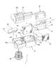
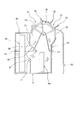
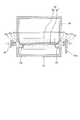
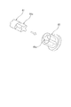
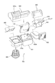
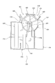
- 1 is an exploded view of a first embodiment of the present invention. It is a typical sectional view of a 1st embodiment of the present invention. It is a typical sectional view of the rotation axis support structure of a 1st embodiment of the present invention. It is a fragmentary perspective view of the rotating shaft support structure of the 1st Embodiment of this invention. It is a fragmentary perspective view of the rotating shaft support structure of the 1st Embodiment of this invention. It is a fragmentary perspective view of the rotating shaft support structure of the 1st Embodiment of this invention. It is a fragmentary perspective view of the rotating shaft support structure of the 1st Embodiment of this invention. It is typical sectional drawing of the rotating shaft support structure of the 2nd Embodiment of this invention.
- FIG. 1 is a perspective view of a vehicle air conditioner according to a first embodiment of the present invention
- FIG. 2 is an exploded view
- FIG. 3 is a view of the vehicle air conditioner 1 of FIG. It is typical sectional drawing.
- the vehicle air conditioner 1 is mounted in front of the interior of a vehicle, and is roughly divided into a blower mechanism (left side in FIG. 1) that sends an air flow, and a temperature condition that cools and heats the air flow. 1 and a part of the lower case 10, a part of the first upper case 20, a blower 80, an inside / outside air switching door 90, etc. Part, first upper case 20, second upper case 30, cooling heat exchanger 40, heating heat exchanger 50, air mix door 60, mode door 70 (also referred to as air distribution door), etc. Configure the mechanism.
- FIG. 3 shows a schematic cross-sectional view on the temperature conditioning mechanism side.
- the inside / outside air switching door 90, the air mix door 60, and the mode door 70 may be collectively referred to as an air passage switching door or simply a door.
- the lower case 10 has a box-like shape that is disposed below the vehicle in the vertical direction, has a space inside, and is open at the top.
- the plurality of upper cases are stacked one layer above the lower case 10 along the vertical direction of the vehicle, the lower part is opened, and the upper case is combined with the lower case 10 to form an internal space.
- a case 20 and a second upper case 30 are provided.
- the blower mechanism side has, in the first upper case 20, an outside air introduction port (not shown) for guiding air outside the vehicle and an inside air introduction port 20a for guiding the air inside the vehicle.
- the temperature conditioning mechanism side includes a first upper case 20, a defrost opening 21, a second upper case 30, and a vent opening 31 for blowing air toward the driver's upper body. And a foot opening 32 for blowing air to the feet.
- the inside / outside air switching door 90 adjusts the ratio of the air taken into the vehicle air conditioner 1 between the outside air introduced from the outside air inlet (not shown) and the inside air introduced from the inside air inlet 20a.
- the cross section is shown as a rotary door having an arc-shaped outer peripheral portion, fan-shaped portions at both ends thereof, and a rotating shaft 91 penetrating through the center portions of the fan-shaped portions on both sides. Provided upstream. The support structure of the rotation shaft 91 of the inside / outside air switching door 90 will be described later.
- the blower 80 guides the air introduced from the outside air inlet (not shown) and / or the inside air inlet 20a to the cooling heat exchanger 40.
- the blower 80 includes an impeller and a motor that rotates the impeller, and is mounted on the blower mechanism side of the lower case 10.
- the cooling heat exchanger 40 is disposed in an internal space formed by the lower case 10 and the first upper case 20, and is connected to a known refrigeration cycle. Air that flows through the internal space is circulated. It is possible to cool.
- the heating heat exchanger 50 is an internal space formed by the lower case 10 and the second upper case 30 and is arranged behind the cooling heat exchanger 40 in the front-rear direction of the vehicle. It is connected, and it is possible to heat all or part of the air that has flowed through the cooling heat exchanger 40.
- the air mix door 60 uses an airflow (cold air) that bypasses the heating heat exchanger 50 and an airflow that passes through the heating heat exchanger 50 (air) (air) that passes through the cooling heat exchanger 40 and is sent to the mode door 70.
- the ratio with warm air is adjusted.
- it is shown as a cantilever door having a rotating shaft 61 and a closing portion 62 extending from the rotating shaft 61, and between the cooling heat exchanger 40 and the heating heat exchanger 50. Is provided.
- a support structure for the rotation shaft 61 of the air mix door 60 will be described later.
- the mode door 70 distributes the conditioned air to a desired outlet for the air conditioned by the vehicle air conditioner 1.
- the cross section is shown as a rotary door including an outer peripheral portion having an arc shape, fan-shaped portions at both ends thereof, and a rotating shaft 71 penetrating through the center portions of the fan-shaped portions on both sides, and a defrost opening 21, the vent opening 31 and the foot opening 32 are provided in the vicinity, and an opening for ventilation is appropriately provided on the outer peripheral portion.
- a support structure for the rotation shaft 71 of the mode door 70 will be described later.
- FIG. 4 is a schematic cross-sectional view of the rotating shaft support structure of the first embodiment of the vehicle air conditioner according to the present invention, and a cut surface at a plane orthogonal to the plane A shown in FIG. Is. 5, 6 and 7 are partial perspective views of the rotating shaft support structure of the first embodiment of the vehicle air conditioner of the present invention.
- air mix door mounting holes 63 a and 63 b and mode door mounting holes 73 a and 73 b are provided on the left and right side surfaces of the right portion (temperature conditioning mechanism side) of the lower case 10.
- the rotation shaft 61 of the air mix door 60 is formed to be shorter than the left and right inner widths of the lower case 10, and both ends of the rotation shaft 61 are installed in the internal space of the vehicle air conditioner.
- the lower case 10 is provided with rotating shaft placement portions 13 a and 13 b that protrude inward of the lower case 10.
- FIG. 5 is a partial perspective view of the rotating shaft support structure of the first embodiment of the present invention, showing a part of the inner wall surface of the lower case 10 from the inner space side of the vehicle air conditioner.
- the rotating shaft mounting portion 13a (13b) protrudes from the air mix door mounting hole 63a (63b) to the inside of the lower case 10 and has a concave upper surface so that the rotating shaft 61 can be stably mounted. It is formed in a cross-sectional shape.
- one end (right end) of the rotating shaft 61 is stepped, and the tip portion 61a has a substantially cross-shaped cross section.
- the tip portion 61a has two steps. Are inserted into a stopper 65 having a substantially cross-shaped hole 65a at the end of the narrow diameter side.
- the other end (left end) of the rotating shaft 61 is stepped, the tip portion 61b is formed in a substantially cross shape, and the tip portion 61b has two steps.
- a thick cylinder formed from a cylinder has a flat plate portion 66a and is inserted into a lever 66 having a substantially cross-shaped hole 66b at the end of the narrow diameter side.
- the rotation shaft 61 can be rotated integrally by fitting the both ends of the rotation shaft 61 with the substantially cross-shaped portion of the stopper 65 and the lever 66.
- the end on the narrow side is freely fitted in a well-known manner while maintaining airtightness with the air mix door mounting hole 63a of the lower case 10, and the axial movement of the rotary shaft 61 is restricted. is doing.
- the end portion of the cylindrical portion of the lever 66 is freely fitted to the air mix door mounting hole 63b of the lower case 10 in a well-known manner while maintaining airtightness.
- a known mechanism such as a method using a link (Japanese Patent Application Laid-Open No. 2004-189110) may be used in addition to providing a substantially cross-shaped portion.
- rotation shaft placement portions 13a and 13b are provided at positions away from the rotation shaft 61 when the assembly is completed.
- the rotation shaft 71 of the mode door 70 is provided with a stopper 75, lever, and mode door mounting holes 73a, 73b on the right side portion of the lower case 10 (temperature conditioning mechanism side).
- the inside / outside air switching door 90 is supported by a similar structure using the inside / outside air switching door mounting holes 93a, 93b on the left side portion (air blowing mechanism side) of the lower case 10, and a stopper and lever (not shown) are used. It is attached with the same structure using.
- FIG. 3 the airflow is indicated by arrows.
- the outside air and / or the inside air introduced into the space formed by the lower case 10, the first upper case 20, and the second upper case 30 from the inside / outside air switching door 90 is directed toward the cooling heat exchanger 40 by the blower 80. And circulated.
- the airflow that has passed through the cooling heat exchanger 40 is guided by the air mix door 60 in the direction of the heating heat exchanger 50 or in the direction not passing through the heating heat exchanger 50 (an alternative route).
- the airflow in both directions can be blown by appropriately changing the mixing ratio.
- the turning position of the air mix door 60 can be performed by turning the turning shaft 61 by turning the flat plate portion 66a of the lever 66 by a drive mechanism (not shown).
- the airflow passing through the heating heat exchanger 50 is heated by the heating heat exchanger 50, becomes warm air, and reaches a space (air mix space) where the mode door 70 is disposed.
- the airflow that bypasses the heat exchanger 50 for heating reaches the space (air mix space) in which the mode door 70 is arranged without being heated by the heat exchanger 50 for heating, with the cold air.
- both hot air and cold air are present, they merge in the space (air mix space) in which the mode door 70 is disposed, and the temperatures are harmonized.
- the airflow flows out to a plurality of openings of the defrost opening 21, the vent opening 31, the foot opening 32, or a combination thereof depending on the rotational position of the mode door 70.
- the turning position of the mode door 70 can be performed by turning the turning shaft 71 by turning the flat plate portion of the lever with a drive mechanism (not shown).
- the lower case 10 is placed on a horizontal plane with the opening facing up.
- the cooling heat exchanger 40 is placed on the lower case 10 in an upright position so that the airflow direction is the vehicle front-rear direction. Further, the heat exchanger 50 for heating is similarly placed in a standing position.
- both ends of the rotation shaft 61 of the air mix door 60 are mounted on the rotation shaft mounting portions 13 a and 13 b of the lower case 10.
- the stopper 65 is moved closer to the left side of the lower case 10 and the lever 66 is moved closer to the right side of the lower case 10, so that both end portions 61 a and 61 b of the rotating shaft 61 are connected to the hole 65 a of the stopper 65 and the hole 66 a of the lever 66. Further, the cylindrical portions of the stopper 65 and the lever 66 on the narrow diameter side are fitted into the mounting holes 63a and 63b of the lower case 10 so as to be rotatable.
- the mode door 70 is assembled to the lower case 10 in the same manner as the air mix door 60.
- the second upper case 30 is moved from above and brought into close contact with the lower case 10.
- the fitting part P2 (refer FIG. 3) of the lower case 10 and the 2nd upper case 30, it is desirable to take a conventionally known airtight countermeasure.
- the inside / outside air switching door 90 is assembled to the lower case 10 in the same manner as the air mix door 60 on the air blowing mechanism side.
- the first upper case 20 is moved from above and brought into close contact with the lower case 10 to firmly fix the cooling heat exchanger 40. It is also desirable to take a conventionally known airtight countermeasure for the fitting portion P1 between the lower case 10 and the first upper case 20 and the fitting portion P3 between the first upper case 20 and the second upper case 30.
- the main elements of the vehicle air conditioner can be assembled sequentially from above, which is extremely effective for improving work efficiency and automation (robotization).
- the step of inserting the stopper and the lever may be performed from the left-right direction after the first upper case and the second upper case are assembled.
- rotation shaft placement portions 13a and 13b for temporarily supporting the rotation shaft 61 of the air mix door 60 during assembly are provided, and the rotation shaft placement portions 13a and 13b are rotated after the assembly is completed.
- the rotating shaft 61 is held in such a state that one or both rotating shaft mounting portions can be rotated with a well-known bearing function in this portion even after the assembly is completed. It is good also as a rotating shaft support part.
- the rotation shaft is placed on the rotation shaft support portion during the assembly of the apparatus, the assemblability in the assembly from above becomes better, and further, the support of the rotation shaft can be supported after the assembly.
- the overall structure may be simplified and the manufacturing cost may be reduced.
- the door shape also made the air mix door 60 cantilever and the mode door 70 and the inside / outside air switching door 90 a rotary type, it is not limited to this, butterfly type which provided the obstruction
- the second upper case 30 and the first upper case 20 are assembled in the order of assembling order, but the order may be reversed from the situation such as pre-assembly of other components. In some cases, efficiency can be increased.
- the air mix door 60, the mode door 70, or the inside / outside air switching door 90 is sequentially assembled, it may be pre-assembled in the lower case 10 in advance. The advantage that the final assembly is simplified can also be considered.
- FIG. 8 is a schematic cross-sectional view of the rotating shaft support structure in this embodiment of the vehicle air conditioner of the present invention.
- the air mix door 160 will be described, but it can also be applied to other mode doors and inside / outside air switching doors.
- the rotation shaft 161 of the air mix door 160 is formed shorter than the left and right inner widths of the lower case 110, and both ends of the rotation shaft 161 are installed in the internal space of the vehicle air conditioner. Become. Further, the rotation shaft 161 is mounted on rotation shaft mounting portions 113 a and 113 b provided inside the lower case 110. However, the position of the rotating shaft 161 is not a mounting hole provided in the lower case 110, but bearing portions 169a and 169b (split bearings) that are vertically divided into fitting portions between the lower case 110 and the second upper case 130. (Also called). Since other structures are the same as those of the first embodiment, description thereof is omitted. *
- both ends of the rotation shaft 161 of the air mix door 160 are mounted on the rotation shaft mounting portions 113 a and 113 b of the lower case 110.
- the stopper 165 is moved closer to the left side of the lower case 110, the lever 166 is moved closer to the right side of the lower case 110, both ends of the rotating shaft 161 are inserted into the stopper 165 and the lever 166, and the stopper 165 and lever 166 are moved further.
- the lower side of the cylindrical portion on the narrow diameter side is rotatably mounted on the bearing portions 169a and 169b on the lower case 110 side. In this state, the movement of the rotating shaft 161 in the axial direction is restricted by the stopper 165.
- the rotation shaft 161 is separated from the rotation shaft mounting portions 113a and 113b, and does not come into contact with the rotation shaft mounting portions 113a and 113b.
- the rotation shaft 161 of the air mix door 160 is provided with the bearing portions 169a and 169b that are vertically divided into the fitting portions between the lower case 110 and the second upper case 130 via the stopper 165 and the lever 166. Is supported rotatably.
- FIG. 9 is a schematic view of this embodiment of the vehicle air conditioner of the present invention.
- the air mix door 260 will be described, but it can also be applied to other mode doors and inside / outside air switching doors.
- the structure of the lower case 210 is such that one side (right side) wall surface is high and the other side (left side) wall surface is low.
- the rotation shaft 261 of the air mix door 260 is formed shorter than the left and right inner widths of the lower case 210, and both ends of the rotation shaft 261 are installed in the internal space of the vehicle air conditioner.
- the rotation shaft placement portions 213a and 213b are provided inside the lower case 210, and the rotation shaft 261 is placed during the assembly.
- one end (right end) is inserted into the lever 266 inserted into the mounting hole 263 provided in the lower case 210, and the other end (left end) is the lower case 210 and the second upper case 230. It is inserted in the stopper 265 mounted on the bearing part 269 provided in the fitting part. That is, the first embodiment and the second embodiment are mixed.
- FIG. 10 is a schematic diagram of this embodiment of the vehicle air conditioner of the present invention.
- the air mix door 360 will be described, but it can also be applied to other mode doors and inside / outside air switching doors.
- the rotation shaft 316 has such a length that only one end (right end) exists inside the lower case 310 and the other end (left end) extends to the outside of the lower case 310.
- the structure of the lower case 310 is such that the one side (right side) wall surface is high and the other side (left side) wall surface is low, and the rotation shaft placing portion 313 is provided only on one side (right side) inside the lower case 310, On the other side, a bearing portion 369 is provided between the lower case 310 and the second upper case 330.
- one end is inserted into the lever 366 inserted into the mounting hole 363 provided in the lower case 310.
- the other end (left end) is placed on a lower portion of a bearing portion 369 (split bearing) provided in a fitting portion between the lower case 310 and the second upper case 330, and further protrudes out of the lower case 310.
- a stopper 365 is inserted into the tip of the rotating shaft 361.
- FIG. 1 is a perspective view of a vehicle air conditioner according to this embodiment of the present invention in common with the first embodiment
- FIG. 11 is an exploded view
- FIG. 12 is a vehicle air conditioner of FIG. 1 according to this embodiment.
- FIG. 13 is a schematic cross-sectional view of the rotating shaft support structure of this embodiment.
- FIG. 13 is a cross-sectional view taken along a plane orthogonal to the plane A shown in FIG. It is a thing.
- FIG. 14 is a partial assembly view of the rotating shaft of this embodiment.
- the vehicle air conditioner 400 is installed in front of the interior of the vehicle, and is installed so that the front-rear direction in FIG. 1 is the traveling direction of the vehicle.
- a blower mechanism left side in FIG. 1
- a temperature conditioning mechanism right side in FIG. 1 that cools and heats the airflow.
- a part of the lower case 410, the first upper part A part of the case 420, a blower 480, an inside / outside air switching door 490, and the like constitute a blowing mechanism
- a part of the lower case 410, a part of the first upper case 420, a second upper case 430, and a cooling heat exchanger 440 constitute a temperature harmony mechanism.
- the lower case 410 has a box shape that is disposed below the vehicle in the vertical direction, has a space inside, and is open at the top.
- the plurality of upper cases are stacked one layer above the lower case 410 along the vertical direction of the vehicle, the lower part is opened, and are combined with the lower case 410 to form an internal space.
- a case 420 and a second upper case 430 are provided.
- the blower mechanism side has, in the first upper case 420, an outside air introduction port (not shown) for guiding air outside the vehicle and an inside air introduction port 420a for guiding the air inside the vehicle.
- the temperature conditioning mechanism side has a first upper case 420, a defrost opening 421, a second upper case 430, a vent opening 431 for blowing air toward the driver's upper body, And a foot opening 432 for blowing air to the feet.
- a foot duct 495 may be added to the vehicle air conditioner 400 later as needed.
- the inside / outside air switching door 490 adjusts the ratio between the outside air introduced from the outside air inlet (not shown) and the inside air introduced from the inside air inlet 420a with respect to the air taken into the vehicle air conditioner 400.
- the cross section is shown as a rotary door having an arc-shaped outer peripheral portion, fan-shaped portions at both ends thereof, and a rotation shaft penetrating the central portion of the fan-shaped portions on both sides, and upstream of the blower 480.
- the rotation shaft of the inside / outside air switching door 490 is rotatably held in any one of the first to fourth embodiments, and is a rotation drive source (not shown) at a lever portion protruding from the lower case 410 to the outside. Concatenated with As is well known, the inside / outside air switching door 490 can be stopped at an intermediate position.
- the blower 480 guides the air introduced from the outside air inlet (not shown) and / or the inside air inlet 420a to the cooling heat exchanger 440.
- the blower 480 includes an impeller and a motor that rotates the impeller, and is mounted on the blower side of the lower case 410.
- the cooling heat exchanger 440 is disposed in an internal space formed by the lower case 410 and the first upper case 420 and is connected to a well-known refrigeration cycle. Air that flows through the internal space is circulated. It is possible to cool.
- the heating heat exchanger 450 is an internal space formed by the lower case 410 and the second upper case 430, and is disposed behind the cooling heat exchanger 440 in the front-rear direction of the vehicle. It is connected, and it is possible to heat all or part of the air flowing through the cooling heat exchanger 440.
- the air mix door 460 passes the cooling heat exchanger 440 and the air sent to the mode door 470.
- the air mix door 460 bypasses the heating heat exchanger 450 (cold air) and the air flow passing through the heating heat exchanger 450 ( The ratio with warm air is adjusted.
- the cross section is shown as a rotary door including an outer peripheral portion having an arc shape, fan-shaped portions at both ends thereof, and a rotating shaft 461 extending from the center portion of the fan-shaped portions on both sides, and the heating heat Provided above the exchanger 450.
- the support structure of the rotation shaft 461 of the air mix door 460 will be described later.
- the mode door 470 distributes conditioned air to a desired outlet for the air conditioned by the vehicle air conditioner 400.
- the cross section is shown as a rotary door comprising an outer peripheral portion having an arc shape, fan-shaped portions at both ends thereof, and a rotating shaft 471 extending from the center portion of the fan-shaped portions on both sides, and a defrost opening 421, the vent opening 431, and the foot opening 432 are provided in the vicinity, and an opening for ventilation is appropriately provided on the outer periphery.
- a support structure for the rotation shaft 471 of the mode door 470 will be described later.
- the rotation shaft 461 of the air mix door 460 and the rotation shaft 471 of the mode door 470 are arranged on the same axis, but can be independently rotated.
- mounting holes 463a and 463b common to the air mix door and the mode door are provided on the left and right side surfaces of the right portion (temperature conditioning mechanism side) of the lower case 410.
- the air mix door 460 and the mode door 470 are formed shorter than the left and right inner widths of the lower case 410.
- the lower case 410 is provided with rotating shaft placing portions 413a and 413b having a shape protruding inside the lower case 410.
- One end (left end) 461a of the rotation shaft 461 of the air mix door 460 has a cylindrical hole 464 to which a lever 466 is integrally pivotably coupled on the left side, and the mode door 470 on the right side.
- the one end 471a has a cylindrical hole portion into which the end 471a is freely fitted.
- the other end (right end) 461b is fitted to one end (right end) 471b of the rotation shaft 471 of the mode door 470 so as to freely rotate.
- one end (left end) 471a of the rotation shaft 471 of the mode door 470 is freely fitted to the right of the rotation shaft right end 461a of the air mix door 460
- the other end ( (Right end) 471b has a cylindrical hole portion 474 to which a lever 476 is integrally pivotally coupled on the right side, and one end 461b of the air mix door 460 is freely fitted on the left side. It has a cylindrical hole.
- the rotation shaft placement portions 413a and 413b are arranged on the upper surface so that the air mix door rotation shaft 461a and the mode door rotation shaft 471b can be stably placed, respectively.
- the rotation shaft 461 is coupled to the lever 466 so that the rotation shaft 461 can rotate integrally with the lever 466 at one end (left end), and the rotation shaft 471 is integrated with the lever 476 at one end (right end). It is pivotally connected.
- rotation shaft placement portions 413a and 413b are provided at positions away from the rotation shaft 461 when the assembly is completed.
- this portion may have a well-known bearing function and be a rotatable state so as to be a rotation shaft support portion that holds the rotation shafts 461 and 471. .
- FIG. 13 the airflow is indicated by arrows.
- the outside air and / or the inside air introduced into the space formed by the lower case 410, the first upper case 420, and the second upper case 430 from the inside / outside air switching door 490 is directed toward the cooling heat exchanger 440 by the blower 480. And circulated.
- the airflow that has passed through the cooling heat exchanger 440 is guided by the air mix door 460 toward the heating heat exchanger 450 or in a direction that does not pass through the heating heat exchanger 450 (an alternative route).
- the airflow directed in both directions can be blown by appropriately changing the mixing ratio.
- the rotation position of the air mix door 460 can be performed by rotating the rotation shaft 461 by turning the flat plate portion 466a of the lever 466 by a driving mechanism (not shown).
- the airflow that passes through the heat exchanger for heating 450 is heated by the heat exchanger for heating 450, becomes warm air, and reaches a space (air mix space) where the mode door 470 is disposed.
- the airflow that bypasses the heat exchanger for heating 450 reaches the space (air mix space) in which the mode door 470 is arranged without being heated by the heat exchanger for heating 450, with cold air.
- both hot air and cold air are present, they merge in the space (air mix space) in which the mode door 470 is disposed, and the temperatures are harmonized.
- the airflow flows out to a plurality of openings of the defrost opening 421, the vent opening 431, the foot opening 432, or a combination thereof depending on the rotation position of the mode door 470.
- the turning position of the mode door 470 can be performed by turning the turning shaft 471 by turning the flat plate portion 476a of the lever 476 by a driving mechanism (not shown).
- the lower case 410 is placed on a horizontal plane with the opening facing up.
- the cooling heat exchanger 440 is placed on the lower case 410 in an upright position so that the airflow direction is the vehicle longitudinal direction. Further, the heat exchanger 450 for heating is similarly placed in a standing position.
- the air mix door 460 and the mode door 470 are pre-assembled so as to be pivotable to form a door assembly. 413a and 413b.
- an example of a method of pre-assembly is to move the mode door 470 from the air mix door 460 to a lower position with the mode door 470 slightly shifted from the air mix door 460.
- the door 470 may be moved.
- the second upper case 430 is moved from above and fitted with the lower case 410. Furthermore, it is desirable to take a conventionally known airtight countermeasure for the fitting portion P42 between the lower case 410 and the second upper case 430.
- the inside / outside air switching door 490 is assembled to the lower case 410 on the air blowing mechanism side by any one of the methods of the first to fourth embodiments.
- the first upper case 420 is moved from above and brought into close contact with the lower case 410 to firmly fix the cooling heat exchanger 440. Furthermore, it is desirable to take a conventionally known airtight countermeasure for the fitting portion P41 between the lower case 410 and the first upper case 420 and the fitting portion P43 between the first upper case 420 and the second upper case 130.
- the main elements (except for some pre-assembled elements) of the vehicle air conditioner can be assembled sequentially from above, which is extremely effective for work efficiency and automation (robotization). .
- the cooling heat exchanger 440 and the heating heat exchanger 450 are provided along the vehicle front-rear direction, but may be provided along the vehicle left-right direction. In that case, the air mix door 460 extends in the vehicle front-rear direction. Such an arrangement may be effective depending on the space situation in the vehicle.
- the door shape is a rotary type for both the air mix door 460 and the mode door 470. Any type of door may be used. An appropriate mold may be selected based on the request for airflow control and the manufacturing cost.
- the second upper case 430 and the first upper case 420 are assembled in the order of assembly in the order of assembly, but the order is reversed from the situation such as pre-assembly of other components. Also good. In some cases, efficiency can be increased.
- the upper case has been described as the first upper case and the second upper case.
- the upper case may be further subdivided to increase the number of the upper cases to 3 or more.
- the number of members is increased by changing the air blowing mechanism side of the first upper case to the third upper case.
- the assemblability is improved and the number of assembling steps or time can be reduced, it is effective in reducing the overall cost.
- the lower case has been described as being placed on the horizontal surface with the opening side up, but before the lower case is placed, the impeller is placed above the impeller.
- the lower case may be moved from above and fixed.
- the vehicle air conditioner including the blower can be stacked and assembled from the bottom to the top.
- the vehicle air conditioner according to the present invention is an invention that can be industrially manufactured and can be used as an object of commerce, and thus can be used industrially with economic value.
Landscapes
- Physics & Mathematics (AREA)
- Thermal Sciences (AREA)
- Engineering & Computer Science (AREA)
- Mechanical Engineering (AREA)
- Air-Conditioning For Vehicles (AREA)
Abstract
[Problème] L'invention vise à proposer un dispositif de climatisation de véhicule qui présente peu de restrictions en termes de forme et de disposition de boîtiers et de trappes et qui est facile à assembler. [Solution] Un dispositif de climatisation de véhicule selon l'invention comporte: un boîtier inférieur disposé du côté inférieur dans la direction verticale d'un véhicule; des boîtiers supérieurs empilés sur le boîtier inférieur suivant la direction verticale du véhicule et formant un espace interne avec le boîtier inférieur; et des trappes, possédant chacune un axe de rotation et disposées de façon pivotante à l'intérieur de l'espace interne, régulant ainsi un flux d'air s'écoulant à travers l'espace interne, une ou les deux extrémités de l'axe de rotation étant logées à l'intérieur de l'espace interne.
Applications Claiming Priority (2)
| Application Number | Priority Date | Filing Date | Title |
|---|---|---|---|
| JP2016018394 | 2016-01-15 | ||
| JP2016-018394 | 2016-08-30 |
Publications (1)
| Publication Number | Publication Date |
|---|---|
| WO2017122807A1 true WO2017122807A1 (fr) | 2017-07-20 |
Family
ID=59311194
Family Applications (1)
| Application Number | Title | Priority Date | Filing Date |
|---|---|---|---|
| PCT/JP2017/001096 Ceased WO2017122807A1 (fr) | 2016-01-15 | 2017-01-13 | Dispositif de climatisation de véhicule |
Country Status (1)
| Country | Link |
|---|---|
| WO (1) | WO2017122807A1 (fr) |
Citations (6)
| Publication number | Priority date | Publication date | Assignee | Title |
|---|---|---|---|---|
| JPS6111413U (ja) * | 1984-06-27 | 1986-01-23 | 株式会社デンソー | 気流切換弁 |
| JPH02120210U (fr) * | 1989-03-15 | 1990-09-27 | ||
| JPH0377705U (fr) * | 1989-11-30 | 1991-08-06 | ||
| JP2000046410A (ja) * | 1998-07-28 | 2000-02-18 | Denso Corp | 空気通路切替装置 |
| JP2000198342A (ja) * | 1999-01-07 | 2000-07-18 | Denso Corp | 車両用空調装置 |
| JP2004243826A (ja) * | 2003-02-12 | 2004-09-02 | Denso Corp | 空気通路切替装置 |
-
2017
- 2017-01-13 WO PCT/JP2017/001096 patent/WO2017122807A1/fr not_active Ceased
Patent Citations (6)
| Publication number | Priority date | Publication date | Assignee | Title |
|---|---|---|---|---|
| JPS6111413U (ja) * | 1984-06-27 | 1986-01-23 | 株式会社デンソー | 気流切換弁 |
| JPH02120210U (fr) * | 1989-03-15 | 1990-09-27 | ||
| JPH0377705U (fr) * | 1989-11-30 | 1991-08-06 | ||
| JP2000046410A (ja) * | 1998-07-28 | 2000-02-18 | Denso Corp | 空気通路切替装置 |
| JP2000198342A (ja) * | 1999-01-07 | 2000-07-18 | Denso Corp | 車両用空調装置 |
| JP2004243826A (ja) * | 2003-02-12 | 2004-09-02 | Denso Corp | 空気通路切替装置 |
Similar Documents
| Publication | Publication Date | Title |
|---|---|---|
| JP5473449B2 (ja) | 車両用空調装置 | |
| JP4395523B2 (ja) | 車両空調装置用吹出しモードドアおよびそれを用いた車両空調装置 | |
| JP4561693B2 (ja) | 車両用空調装置の空気通路開閉装置 | |
| JP6341114B2 (ja) | 車両用空調装置 | |
| JP2009202687A (ja) | 車両用空調装置 | |
| JPWO2017022652A1 (ja) | 車両用空調装置 | |
| WO2014058009A1 (fr) | Dispositif de conditionnement d'air pour véhicule | |
| JP6234747B2 (ja) | 車両用空調装置 | |
| JP2015016783A (ja) | 車両用空調装置 | |
| JP4013688B2 (ja) | 車両用空調装置 | |
| JP2005225445A (ja) | 自動車用空調装置 | |
| JP4755931B2 (ja) | 車両用空調装置の空気取入構造 | |
| JP6310660B2 (ja) | 車両用空調装置 | |
| JP6262790B2 (ja) | 車両用空調装置及びその組み付け方法 | |
| JP2002019448A (ja) | 車両用空調装置 | |
| JP4783942B2 (ja) | 自動車用空調装置 | |
| JP2006341772A (ja) | 空調装置のリンクプレート支持構造 | |
| JP2012158219A (ja) | 車両用空調装置 | |
| JP2006341707A (ja) | 車両用空調装置 | |
| JP2004276624A (ja) | 空気流路開閉用ドアリンク機構および車両用空調装置 | |
| JP2021003958A (ja) | 空調装置 | |
| KR20140073172A (ko) | 차량용 후석 공조장치 | |
| JP2010208596A (ja) | 車両用空調装置のドア構造 | |
| JP2005082112A (ja) | 車両用空調ユニット | |
| JP2006036004A (ja) | 車両用空調ユニット |
Legal Events
| Date | Code | Title | Description |
|---|---|---|---|
| 121 | Ep: the epo has been informed by wipo that ep was designated in this application |
Ref document number: 17738559 Country of ref document: EP Kind code of ref document: A1 |
|
| NENP | Non-entry into the national phase |
Ref country code: DE |
|
| 122 | Ep: pct application non-entry in european phase |
Ref document number: 17738559 Country of ref document: EP Kind code of ref document: A1 |
|
| NENP | Non-entry into the national phase |
Ref country code: JP |