WO2017122811A1 - Bord de haut-parleur - Google Patents
Bord de haut-parleur Download PDFInfo
- Publication number
- WO2017122811A1 WO2017122811A1 PCT/JP2017/001109 JP2017001109W WO2017122811A1 WO 2017122811 A1 WO2017122811 A1 WO 2017122811A1 JP 2017001109 W JP2017001109 W JP 2017001109W WO 2017122811 A1 WO2017122811 A1 WO 2017122811A1
- Authority
- WO
- WIPO (PCT)
- Prior art keywords
- fiber
- elastomer
- entangled body
- fibers
- speaker
- Prior art date
- Legal status (The legal status is an assumption and is not a legal conclusion. Google has not performed a legal analysis and makes no representation as to the accuracy of the status listed.)
- Ceased
Links
Images




Classifications
-
- H—ELECTRICITY
- H04—ELECTRIC COMMUNICATION TECHNIQUE
- H04R—LOUDSPEAKERS, MICROPHONES, GRAMOPHONE PICK-UPS OR LIKE ACOUSTIC ELECTROMECHANICAL TRANSDUCERS; ELECTRIC HEARING AIDS; PUBLIC ADDRESS SYSTEMS
- H04R1/00—Details of transducers, loudspeakers or microphones
- H04R1/02—Casings; Cabinets ; Supports therefor; Mountings therein
-
- H—ELECTRICITY
- H04—ELECTRIC COMMUNICATION TECHNIQUE
- H04R—LOUDSPEAKERS, MICROPHONES, GRAMOPHONE PICK-UPS OR LIKE ACOUSTIC ELECTROMECHANICAL TRANSDUCERS; ELECTRIC HEARING AIDS; PUBLIC ADDRESS SYSTEMS
- H04R7/00—Diaphragms for electromechanical transducers; Cones
- H04R7/16—Mounting or tensioning of diaphragms or cones
- H04R7/18—Mounting or tensioning of diaphragms or cones at the periphery
- H04R7/20—Securing diaphragm or cone resiliently to support by flexible material, springs, cords, or strands
-
- H—ELECTRICITY
- H04—ELECTRIC COMMUNICATION TECHNIQUE
- H04R—LOUDSPEAKERS, MICROPHONES, GRAMOPHONE PICK-UPS OR LIKE ACOUSTIC ELECTROMECHANICAL TRANSDUCERS; ELECTRIC HEARING AIDS; PUBLIC ADDRESS SYSTEMS
- H04R9/00—Transducers of moving-coil, moving-strip, or moving-wire type
- H04R9/02—Details
Definitions
- This invention relates to the edge for speakers provided with the fiber entanglement body.
- Patent Document 1 Conventionally, a speaker edge having polyurethane elastomer fibers and paper pulp and formed by papermaking has been proposed (for example, see Patent Document 1).
- airtightness is improved by filling a gap of paper pulp with polyurethane elastomer fibers (that is, improvement in air resistance defined by JISP8117: 2009).
- the air resistance is a time required for a predetermined volume of air to permeate per unit area and unit pressure difference, and the higher the air resistance, the more difficult the gas passes.
- an object of the present invention is to provide an edge for a speaker that can improve the air permeability resistance with a simple configuration as an example.
- the speaker edge according to claim 1 includes a fiber entangled body in which at least elastomer fibers are entangled, and is located on the front surface or the back surface of the fiber entangled body.
- the elastomer fiber is characterized in that a flat portion along the front surface or the back surface is formed.
- FIG. 2 is a cross-sectional view taken along line XX in FIG. It is a schematic diagram which shows the fiber entanglement body of the said edge for speakers. It is a top view which expands and shows the said fiber entanglement body. It is sectional drawing which expands and shows the said fiber entanglement body, and a perspective view which shows one fiber which comprises this fiber entanglement body. It is a top view which shows the net
- FIG. 6 is a schematic diagram illustrating a fiber entangled body of a speaker edge according to Embodiment 2.
- FIG. FIG. 6 is a cross-sectional view illustrating a speaker edge according to a third embodiment.
- 10 is an enlarged photograph showing a speaker edge according to Example 4.
- FIG. 6 is a schematic diagram illustrating a fiber entangled body of a speaker edge according to Embodiment 2.
- FIG. 6 is a cross-sectional view illustrating a speaker edge according to a third embodiment.
- 10 is an enlarged photograph showing a speaker edge according to Example 4.
- the speaker edge according to the embodiment of the present invention includes a plate-like fiber entangled body in which at least elastomer fibers are entangled, and the elastomer fiber located on the front surface, back surface, near the front surface or near the back surface of the fiber entangled body has a surface or A flat portion along the back surface is formed.
- the plane portion is formed in the elastomer fiber means that the cross section of the elastomer fiber is formed in an oval shape (such as an oval shape or a rounded rectangular shape) having a longitudinal direction in one direction of the fiber entangled body. Means that.
- at least a part of the side surface of the elastomer fiber in which the flat portion is formed is formed in an oval shape (such as an oval shape or a rounded rectangular shape) whose longitudinal direction is the extending direction of the elastomer fiber.
- the area of the elastomer fiber when the fiber entangled body is viewed in plan can be increased as compared with a fiber entangled body having only the elastomer fiber extending in a columnar shape. Therefore, it becomes difficult for gas to pass through the fiber entangled body in the direction perpendicular to the surface (thickness direction), and the air permeability resistance of the speaker edge can be improved.
- the elastomer fiber is easily deformed, and, for example, by applying heat or pressure to the fiber entangled body, the flat portion can be easily formed, and the air resistance can be improved with a simple configuration.
- the same plane part may be formed not only on the surface of the fiber entangled body, the back surface, the vicinity of the front surface, or the elastomer fiber positioned in the vicinity of the back surface, but also on the elastomer fiber positioned in the center portion in the perpendicular direction.
- the fiber entangled body may have unevenness
- the fiber entangled body has a plastic fiber.
- the Young's modulus of the speaker edge can be improved and good acoustic characteristics can be obtained.
- the mass of the elastomer fiber may be equal to or less than the mass of the plastic fiber.
- the equivalent circle diameter of the cross section of the plastic fiber is preferably smaller than the equivalent circle diameter of the cross section of the elastomer fiber. As a result, the Young's modulus can be prevented from becoming too high.
- the equivalent circle diameter of the cross section means the diameter of a circle having the same area as the cross section. That is, a small equivalent circle diameter of a cross section is synonymous with a small cross sectional area.
- the fiber entangled body includes a plurality of fiber bundles each composed of at least two elastomer fibers, and the plurality of fiber bundles are entangled.
- the plurality of fiber bundles are entangled.
- the elastic modulus may be deteriorated due to light (ultraviolet rays) as an environmental factor, but the fiber entanglement is formed by forming a fiber entangled body with a fiber bundle. A decrease in the elastic modulus of the body can be suppressed.
- the elastomer fiber preferably has a fiber length (length in the extending direction) of 5 mm or less.
- the second layer may be formed of a film.
- the fiber entangled body may have natural fibers. Thereby, the Young's modulus of the speaker edge can be appropriately adjusted, and good acoustic characteristics can be obtained.
- a speaker device includes the speaker edge according to any one of the above, a diaphragm, a frame that supports the diaphragm via the speaker edge, a voice coil, and a magnetic circuit. .
- the speaker device of the present embodiment by improving the air permeability resistance of the edge with a simple configuration, good acoustic characteristics can be obtained and the speaker device can be reduced in cost.
- the edge since the edge includes the fiber entangled body, the entire edge can be reduced in weight, and the ratio of the sound pressure obtained with respect to the power supplied to the speaker device (the efficiency of the speaker device) can be improved. . Therefore, power consumption of the speaker device during sound emission can be suppressed.
- a moving body includes the above-described speaker device, and the speaker device is attached to an attached body.
- the mounted body is, for example, a door body, an instrument panel, a pillar, or the like, and may be a portion suitable for mounting in the moving body.
- the mobile body of the present invention since the power consumption of the speaker device is suppressed as described above, the battery capacity of the mobile body is unlikely to decrease. Therefore, when the moving body is, for example, an electric vehicle including a battery and a motor, the cruising distance is unlikely to be shortened even if music or the like is reproduced by the speaker device.
- FIG. 1 is a plan view showing a speaker edge 1A according to Embodiment 1 of the present invention
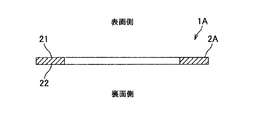
- FIG. 2 is a cross-sectional view taken along line XX of FIG. 1
- FIG. 4 is a schematic view showing the fiber entangled body 2A
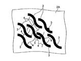
- FIG. 4 is an enlarged plan view showing the fiber entangled body 2A
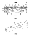
- FIG. 5 is an enlarged sectional view showing the fiber entangled body 2A
- FIG. 6 is a perspective view showing one elastomer fiber 3 constituting 2A
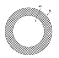
- FIG. 6 is a plan view showing a net M for forming a fiber entangled body 2A
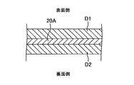
- FIG. 7 shows a fiber entangled body 2A. It is sectional drawing which shows the type
- the speaker edge 1 ⁇ / b> A is configured to be a single layer by a single plate-like fiber entangled body 2 ⁇ / b> A, and has a roll-like cross-sectional shape by a mold or the like, for example. After being formed into a speaker device, it is used for a speaker device (not shown).
- the speaker device is provided, for example, on a vehicle door as a moving body.
- the fiber entangled body 2A is formed in an annular shape in plan view, and a diaphragm (not shown) is provided in the center hole.
- the fiber entangled body 2 ⁇ / b> A is formed by entangled elastomer fibers 3 and plastic fibers 4, and is provided with an additive 5.
- the additive 5 include an ultraviolet absorber and an antioxidant.
- FIG. 4 only the elastomer fiber 3 is shown, and the plastic fiber 4 and the additive 5 are omitted.
- the “front side” of the speaker edge 1A and the fiber entangled body 2A means the sound emission side in the speaker device, and the “back side” means the opposite side.
- the elastomer fiber 3 is an elastic fiber such as an ether-based polyurethane fiber, and its equivalent circle diameter is about 38 to 45 ⁇ m and the melting temperature is 200 ° C. or less. Moreover, the fiber length (length in the extending direction) of the elastomer fiber 3 is 5 mm or less.
- the fiber entangled body 2A two elastomer fibers 3 are in close contact to form a fiber bundle 30, and a plurality of fiber bundles 30 are entangled. As shown in FIG. 5 (A), on the front side and the back side of the elastomer fiber 3 located on the front surface 21 (or the vicinity of the front surface 21) of the fiber entangled body 2A, a flat portion 31 along the front surface 21 is formed.
- the cross section of these elastomer fibers 3 is formed in an oval shape (oval shape, rounded rectangular shape) having a long diameter in one direction in the plane of the fiber entangled body 2A.
- the width of the flat portion 31 (the horizontal dimension in FIG. 5) is, for example, 40 to 50 ⁇ m.
- FIG. 5B shows a single elastomer fiber 3 on which the flat surface portion 31 is formed.
- the elastomer fiber 3 is formed with a flat portion 31 so that a part of the side surface of the elastomer fiber 3 is flat, and the flat surface portion 31 has an extension direction of the elastomer fiber as a longitudinal direction on the side surface of the elastomer fiber 3. It is formed in an oval shape (such as an oval shape or a rounded rectangular shape).
- the planar portion 31 is formed on the elastomer fiber 3 positioned closest to the front surface side and the elastomer fiber 3 positioned next to the front surface side.
- the elastomer fiber 3 may be formed with a flat portion, and it is sufficient that the flat portion is formed at least on the elastomer fiber 3 positioned on the most surface side.
- FIG. 5 for convenience of explanation, it is schematically illustrated that the elastomer fibers 3 are regularly arranged, but actually the elastomer fibers 3 are randomly arranged.
- the flat portion 31 is formed on the elastomer fiber 3 on the back surface 22 side of the fiber entangled body 2A as well as on the front surface 21 side.
- the ether-based polyurethane fiber as the elastomer fiber 3 is easily deteriorated by breaking the ether bond by ultraviolet rays as an environmental factor, and the ether-based polyurethane fiber elastic modulus decreases due to the deterioration.
- the plastic fiber 4 is, for example, a polyethylene fiber, a polypropylene fiber, a polyethylene terephthalate fiber, a polyamide fiber, or the like, and is a fiber having a higher Young's modulus than the elastomer fiber 3, and a fiber whose cross-sectional shape is less likely to be deformed than the elastomer fiber 3. is there.
- the plastic fiber 4 has an equivalent circle diameter of, for example, 4 to 10 ⁇ m, and a glass transition temperature of, for example, 250 ° C. or more. If the equivalent circle diameter of the plastic fiber 4 is too small, the speaker edge may easily absorb water due to capillary action when water enters the speaker device.
- the equivalent circle diameter of the plastic fiber 4 is too large, the Young's modulus of the entire speaker edge becomes too high, and the acoustic characteristics in the low frequency band may be deteriorated. As a decrease in acoustic characteristics in the low frequency band, the lowest resonance frequency is generated on the high frequency band side in the low frequency band.
- the ratio of the mass of the elastomer fiber 3 and the mass of the plastic fiber 4 is, for example, 90:10 to 50:50, and the mass of the elastomer fiber 3 is larger. .
- the Young's modulus of the speaker edge can be adjusted.
- the additive 5 is, for example, an ultraviolet absorber and is dispersed at an appropriate density in the fiber entangled body 2A.
- the fiber entangled body 2A with the ultraviolet absorbent as the additive, it is possible to suppress the elastomer fiber 3 from being deteriorated by the ultraviolet rays and the elastic modulus of the fiber entangled body 2A from being lowered.
- the elastomer fiber 3, the plastic fiber 4, and the additive 5 are dispersed in an appropriate solvent (for example, water) to obtain a stock solution, and a net M as shown in FIG. 6 is immersed in a tank that stores the stock solution.
- an appropriate solvent for example, water
- the mesh M is formed in an annular shape like the fiber entangled body 2A, and the mesh has an appropriate fineness.
- the central portion M1 of the net M may be a hole or a plate. In the case where the central portion M1 is a plate, it is preferable to have water repellency so that the stock solution does not remain on the plate during paper making.
- the elastomer fiber 3, the plastic fiber 4 and the additive 5 By lifting the net M immersed in the tank, the elastomer fiber 3, the plastic fiber 4 and the additive 5 remain on it. By heating the mesh M from above (front side) and below (back side) of the mesh M or sucking water from below, the elastomer fibers 3, the plastic fibers 4 and the additive 5 are dried, and before deformation.
- the fiber entangled body 20A is formed.
- the elastomer fiber 3 extends in a columnar shape and does not have a flat portion.
- the fiber entangled body 20A before deformation is sandwiched from both the front and back surfaces by a pair of molds D1 and D2, and heated and pressed.
- the heating temperature at this time is higher than the glass transition temperature of the elastomer fiber 3 and lower than the melting temperature, and may be higher or lower than the glass transition temperature of the plastic fiber 4.
- the elastomer fiber 3 located in the vicinity of the front surface 21 and the back surface 22 of the fiber entangled body 20 ⁇ / b> A is deformed, and the flat portion 31 is formed.
- the fiber entangled body 2A is formed, and the manufacture of the speaker edge 1A is completed.
- the fiber length of the elastomer fiber 3 is 5 mm or less, the elastomer fiber 3 is prevented from protruding from the outer periphery of the molds D1 and D2, and the elastomer fiber 3 from the desired outer shape of the speaker edge 1A is reduced.
- the protrusion can be suppressed.
- the fiber entangled body 20A Before the fiber entangled body 20A is sandwiched between the pair of molds D1 and D2, the fiber entangled body 20A may not be completely dried, and the fibers are heated and pressed using the pair of molds D1 and D2. The entangled body 20A may be dried.
- the planar portion 31 is formed on the elastomer fiber 3, so that the elastomer fiber 3 when the fiber entangled body 2 ⁇ / b> A is viewed in plan compared to a fiber entangled body having only the elastomer fiber extending in a columnar shape.
- the area can be increased. Therefore, it becomes difficult for gas to pass in the direction perpendicular to the fiber entangled body 2A, and the air resistance of the speaker edge 1A can be improved.
- the planar portion 31 can be formed on the elastomer fiber 3, and the air resistance can be improved with a simple configuration.
- the fiber entangled body 2A has the plastic fiber 4, and the mass of the elastomer fiber 3 is smaller than the mass of the plastic fiber 4, so that the Young's modulus is moderately improved and is not excessively high. Acoustic characteristics can be obtained.
- the equivalent circle diameter of the cross section of the plastic fiber 4 is smaller than the equivalent circle diameter of the cross section of the elastomer fiber 3, the Young's modulus can be prevented from becoming too high.
- the fiber entangled body 2A includes a plurality of fiber bundles 30 composed of two elastomer fibers 3, even if one elastomer fiber 3 is degraded by ultraviolet rays, the other elastomer fiber 3 is not degraded. Moreover, the fall of the elastic modulus of 2 A of fiber entanglement bodies can be suppressed.
- FIG. 8 is a schematic diagram illustrating the fiber entangled body 2B of the speaker edge according to the second embodiment.
- the ratio of the mass of the elastomer fiber 3 and the mass of the plastic fiber 4 is, for example, 49:51 to 10:90, and the mass of the elastomer fiber 3 is smaller. .
- the plastic fiber 4 having a relatively small equivalent circle diameter (in particular, the plastic fiber 4 having a smaller equivalent circle diameter than the elastomer fiber 3) is used for the fiber entangled body 2B of the speaker edge.
- FIG. 9 is a cross-sectional view illustrating the speaker edge 1 ⁇ / b> C according to the third embodiment.
- the speaker edge 1C includes a first layer L1 formed of the fiber entangled body 2C and a second layer L2 stacked on the surface side of the first layer L1.
- the fiber entangled body 2C has, for example, the same configuration as the fiber entangled body 2A of Example 1 or the fiber entangled body 2B of Example 2. That is, the mass ratio between the elastomer fiber 3 and the plastic fiber 4 in the fiber entangled body 2C may be set appropriately.
- the second layer L2 is constituted by a second fiber entangled body 5 in which fibers different from the elastomer fiber 3 are entangled.
- the 2nd fiber entangled body 5 shall be formed with the fiber similar to the natural fiber, such as a pulp, and the plastic fiber 4, for example.
- the second fiber entangled body 5 may be provided with an additive such as an ultraviolet absorber.
- the second layer L2 only needs to have a thickness that makes it difficult to transmit ultraviolet rays to the back side by reflecting or absorbing ultraviolet rays irradiated from the front side.
- the first layer L1 and the second layer L2 may be formed integrally by making one so as to overlap the other, or may be bonded after making each independently.
- the second layer L2 is not limited to the one constituted by the second fiber entangled body 5, and may be constituted by a film.
- the film may be made of, for example, a vinyl chloride-based or polyamide-based material, and is preferably light and has an appropriate Young's modulus.
- a film shall be affixed on the fiber entanglement body 2C.
- the second layer L2 is overlapped on the surface side of the first layer L1, so that the first layer L1 is protected from ultraviolet rays irradiated from the surface side, and the fiber entanglement constituting the first layer L1 It is possible to make the elastomer fiber 3 of the body 2C difficult to deteriorate and to suppress a decrease in the elastic modulus of the fiber entangled body 2C.
- the present invention is not limited to the first to third embodiments, but includes other configurations and the like that can achieve the object of the present invention.
- the following modifications are also included in the present invention.
- the fiber entangled bodies 2A to 2C have the elastomer fibers 3, the plastic fibers 4, and the additive 5.
- the fiber entangled body is one in which at least the elastomer fibers 3 are entangled.
- the plastic fiber 4 and the additive 5 may be omitted.
- the equivalent circle diameter of the cross section of the plastic fiber 4 is smaller than the equivalent circle diameter of the cross section of the elastomer fiber 3, but these equivalent circle diameters are appropriately set according to the required Young's modulus. Any value is acceptable.
- the equivalent circle diameter of the plastic fiber may be greater than or equal to the equivalent circle diameter of the elastomer fiber.
- the fiber bundle 30 is constituted by the two elastomer fibers 3, but the fiber bundle may be constituted by three or more elastomer fibers 3.
- the fiber bundle is not configured. May be.
- the planar portion 31 is formed on the elastomer fiber 3 located in the vicinity of the front surface 21 and the back surface 22 of the fiber entangled body 2A.
- the planar portion is an elastomer fiber located near the surface. 3 may be formed only on the elastomeric fiber 3, or may be formed only on the elastomer fiber 3 located in the vicinity of the back surface.
- the plane part shall be formed in both the surface side and back surface side of the elastomer fiber 3, the plane part may be formed only in the surface side, and the back surface side It may be formed only.
- the fiber length of the elastomer fiber 3 is 5 mm or less.
- the fiber length of the elastomer fiber may be an appropriate length according to the properties of the elastomer fiber, the manufacturing method, and the like. .
- the elastomer fibers are not easily entangled during paper making and easily dispersed, or if the elastomer fibers are difficult to protrude from the outer periphery of the mold during heating and pressurization, use an elastomer fiber having a fiber length longer than 5 mm. Also good.
- ether-based polyurethane fibers that are easily deteriorated by ultraviolet rays are exemplified as the elastomer fibers 3.
- the material is not limited to ultraviolet rays, for example, other than water, temperature, and the like.
- the second layer L2 has an appropriate material, thickness, etc. according to environmental factors that cause degradation of the elastomer fiber. It only has to be.
- a third layer for protecting the first layer from the environmental factor may be provided on the back side of the first layer.
- the fiber entangled body 2A in Example 1 is a combination of two or more fibers of a fiber having a large length, a fiber having a small length, a fiber having a large equivalent circle diameter in cross section, or a fiber having a small equivalent circle diameter in cross section.
- Such two or more fibers may be natural fibers such as pulp.
- an elastomer fiber or a plastic fiber may be added in order to adjust the rigidity of the edge.
- the ratio of the mass of the two or more fibers to the mass of the elastomer fiber or the plastic fiber is 90:10 to 50:50, and the mass of the two or more fibers is larger.
- fibers examples include wood pulp fibers such as sulfite pulp and kraft pulp, non-wood pulp fibers such as bamboo and straw, chemical fibers and synthetic fibers composed of rayon, nylon, vinylon, polyester, acrylic, silk and wool Animal fibers such as manila hemp and cotton, organic fibers composed of graphite, mineral fibers composed of silicon carbide, etc. (glass fibers, carbon fibers, ceramic fibers), minerals composed of basalt, etc. Examples include fibers. Examples of natural fibers here include wood pulp fibers, non-wood pulp fibers, plant fibers, and animal fibers.
- Example 1 the paper product was formed into a plate shape and then formed into a roll shape with a mold. At the stage of forming the paper product, the paper product was formed using a net having a roll-shaped cross section, and dried. It is also possible to do only with the process.
- Example 4 is a fiber entangled body composed of only polyurethane fibers having a fiber length of 5 mm as elastomer fibers, and a flat portion is formed on the elastomer fibers by pressurization and heating as described above.
- a fiber entangled body is composed of the same polyurethane fiber as in Example 4 as an elastomer fiber and a polyamide fiber having a fiber diameter of 0.9 T (decitex) and a fiber length of 5 mm as a plastic fiber, as described above.
- a flat portion is formed on the elastomer fiber by pressurization and heating.
- the mass ratio of polyurethane fiber to polyamide fiber is 8: 2.
- the fiber entangled body is composed of only polyurethane fibers having a fiber length of 5 mm as elastomer fibers, and no flat portion is formed on the elastomer fibers.
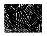
- FIG. 10 shows an enlarged photograph of the surface of the speaker edge of Example 4 as described above.
- the enlarged photograph in FIG. 10 is taken with an electron microscope, and the photographing conditions are shown in the lower left part of the photograph.
- This photo was taken at a magnification of 150 times, but the ratio of the dimensions to the original size in FIG. 10 is different from this magnification.
- the dimensions of each part are shown in the scale bar at the lower right of the photo. As shown.
- the air permeability resistance of the speaker edge was evaluated by the test method described in JISP8117: 2009.
- the respective air resistances were 568 sec in Example 4, 62 sec in Example 5, and 1 sec in Comparative Example 1. That is, good values were obtained with the speaker edges of Examples 4 and 5 in which the flat portion was formed on the elastomer fiber, and the air resistance was insufficient with the speaker edge of Comparative Example 1 in which the flat portion was not formed. It became the value.
- the edge for a speaker of Example 4 which did not contain polyamide fiber as a plastic fiber was particularly good.
- Example 4 the Young's modulus of the speaker edge was evaluated.
- the respective Young's moduli were 3.68 ⁇ 10 7 N / m 2 in Example 4 and 7.99 ⁇ 10 7 N / m 2 in Example 5. That is, the Young's modulus could be improved by including the polyamide fiber as the plastic fiber in the speaker edge of Example 5.
Landscapes
- Engineering & Computer Science (AREA)
- Physics & Mathematics (AREA)
- Acoustics & Sound (AREA)
- Signal Processing (AREA)
- Multimedia (AREA)
- Diaphragms For Electromechanical Transducers (AREA)
Abstract
L'invention concerne un bord de haut-parleur capable d'améliorer la résistance à la perméabilité à l'air avec une configuration simple. La formation de parties plates (31) au moyen de fibres élastomères (3) permet aux superficies des fibres élastomères (3) d'être importantes dans une vue en plan du corps à fibres entrelacées (2A), comparé aux corps à fibres entrelacées qui ont uniquement des fibres élastomères s'étendant suivant des formes cylindriques. Ainsi, un gaz est moins susceptible de s'infiltrer dans la direction orthogonale à la surface du corps à fibres entrelacées (2A), et la résistance à la perméabilité à l'air d'un bord de haut parleur (1A) peut être améliorée. Par application de chaleur et de pression sur le corps à fibres entrelacées (2A), les parties planes (31) peuvent être formées au moyen des fibres élastomères (3) et ainsi, la résistance à la perméabilité à l'air peut être améliorée avec une configuration simple.
Priority Applications (1)
| Application Number | Priority Date | Filing Date | Title |
|---|---|---|---|
| JP2017561203A JP6549253B2 (ja) | 2016-01-15 | 2017-01-13 | スピーカ用エッジ |
Applications Claiming Priority (2)
| Application Number | Priority Date | Filing Date | Title |
|---|---|---|---|
| JP2016006307 | 2016-01-15 | ||
| JP2016-006307 | 2016-01-15 |
Publications (1)
| Publication Number | Publication Date |
|---|---|
| WO2017122811A1 true WO2017122811A1 (fr) | 2017-07-20 |
Family
ID=59311120
Family Applications (1)
| Application Number | Title | Priority Date | Filing Date |
|---|---|---|---|
| PCT/JP2017/001109 Ceased WO2017122811A1 (fr) | 2016-01-15 | 2017-01-13 | Bord de haut-parleur |
Country Status (2)
| Country | Link |
|---|---|
| JP (1) | JP6549253B2 (fr) |
| WO (1) | WO2017122811A1 (fr) |
Citations (3)
| Publication number | Priority date | Publication date | Assignee | Title |
|---|---|---|---|---|
| JPH0353936A (ja) * | 1989-07-21 | 1991-03-07 | Onkyo Corp | 振動部品用積層材料とスピーカ振動部品 |
| JPH0738991A (ja) * | 1993-07-26 | 1995-02-07 | Matsushita Electric Ind Co Ltd | スピーカ用エッジおよびその製造方法 |
| JP2004328795A (ja) * | 1999-03-03 | 2004-11-18 | Onkyo Corp | スピーカー用部材およびその製造方法 |
-
2017
- 2017-01-13 WO PCT/JP2017/001109 patent/WO2017122811A1/fr not_active Ceased
- 2017-01-13 JP JP2017561203A patent/JP6549253B2/ja not_active Expired - Fee Related
Patent Citations (3)
| Publication number | Priority date | Publication date | Assignee | Title |
|---|---|---|---|---|
| JPH0353936A (ja) * | 1989-07-21 | 1991-03-07 | Onkyo Corp | 振動部品用積層材料とスピーカ振動部品 |
| JPH0738991A (ja) * | 1993-07-26 | 1995-02-07 | Matsushita Electric Ind Co Ltd | スピーカ用エッジおよびその製造方法 |
| JP2004328795A (ja) * | 1999-03-03 | 2004-11-18 | Onkyo Corp | スピーカー用部材およびその製造方法 |
Also Published As
| Publication number | Publication date |
|---|---|
| JP6549253B2 (ja) | 2019-07-24 |
| JPWO2017122811A1 (ja) | 2018-11-01 |
Similar Documents
| Publication | Publication Date | Title |
|---|---|---|
| CN1247046C (zh) | 扬声器 | |
| US7344001B2 (en) | Speaker diaphragm and speaker structure | |
| US7849958B2 (en) | Vibration system part for speaker device and manufacturing method thereof | |
| US8369560B2 (en) | Damper and loudspeaker using the same | |
| US11716570B2 (en) | Speaker diaphragm and method of producing speaker diaphragm | |
| US11432072B2 (en) | Speaker diaphragm and production method thereof | |
| CN102543061A (zh) | 薄膜机械阻抗与微穿孔板声阻抗结合的宽频吸声结构 | |
| CN103369449A (zh) | 喇叭振动片的制造方法 | |
| CN101931841A (zh) | 音圈骨架及扬声器 | |
| JP5327268B2 (ja) | 電気音響変換器及び振動板 | |
| JP2011078094A (ja) | 振動板及びそれを利用したスピーカー | |
| WO2017122811A1 (fr) | Bord de haut-parleur | |
| JP2005223807A (ja) | 振動板、その製造方法、および、スピーカ装置 | |
| JP2005223806A (ja) | 振動板、その製造方法、および、スピーカ装置 | |
| JP2016107977A (ja) | 共鳴構造不織布を用いたフードインシュレーター及びこれの製造方法 | |
| CN221873422U (zh) | 具有支撑骨架的吸声橡胶板 | |
| KR101103942B1 (ko) | 저주파수 음역 소음 제어용 흡음판 적층 구조 | |
| CN113518289B (zh) | 具有抗噪层导线的喇叭振动片及其制造方法 | |
| DE10303244B3 (de) | Lautsprecher | |
| CN205847553U (zh) | 用于喇叭振动片的弹性复合结构 | |
| JPH0257096A (ja) | 音響装置用振動板 | |
| CN205510391U (zh) | 具有局部不对称导线通道的多层导线弹波 | |
| JP2002010390A (ja) | スピーカ用エッジ | |
| JP2008085984A (ja) | 電気音響変換器及び振動板 | |
| JP2014187642A (ja) | スピーカ用振動板 |
Legal Events
| Date | Code | Title | Description |
|---|---|---|---|
| 121 | Ep: the epo has been informed by wipo that ep was designated in this application |
Ref document number: 17738563 Country of ref document: EP Kind code of ref document: A1 |
|
| WWE | Wipo information: entry into national phase |
Ref document number: 2017561203 Country of ref document: JP |
|
| NENP | Non-entry into the national phase |
Ref country code: DE |
|
| 122 | Ep: pct application non-entry in european phase |
Ref document number: 17738563 Country of ref document: EP Kind code of ref document: A1 |