WO2017122811A1 - スピーカ用エッジ - Google Patents
スピーカ用エッジ Download PDFInfo
- Publication number
- WO2017122811A1 WO2017122811A1 PCT/JP2017/001109 JP2017001109W WO2017122811A1 WO 2017122811 A1 WO2017122811 A1 WO 2017122811A1 JP 2017001109 W JP2017001109 W JP 2017001109W WO 2017122811 A1 WO2017122811 A1 WO 2017122811A1
- Authority
- WO
- WIPO (PCT)
- Prior art keywords
- fiber
- elastomer
- entangled body
- fibers
- speaker
- Prior art date
- Legal status (The legal status is an assumption and is not a legal conclusion. Google has not performed a legal analysis and makes no representation as to the accuracy of the status listed.)
- Ceased
Links
Images




Classifications
-
- H—ELECTRICITY
- H04—ELECTRIC COMMUNICATION TECHNIQUE
- H04R—LOUDSPEAKERS, MICROPHONES, GRAMOPHONE PICK-UPS OR LIKE ACOUSTIC ELECTROMECHANICAL TRANSDUCERS; ELECTRIC HEARING AIDS; PUBLIC ADDRESS SYSTEMS
- H04R1/00—Details of transducers, loudspeakers or microphones
- H04R1/02—Casings; Cabinets ; Supports therefor; Mountings therein
-
- H—ELECTRICITY
- H04—ELECTRIC COMMUNICATION TECHNIQUE
- H04R—LOUDSPEAKERS, MICROPHONES, GRAMOPHONE PICK-UPS OR LIKE ACOUSTIC ELECTROMECHANICAL TRANSDUCERS; ELECTRIC HEARING AIDS; PUBLIC ADDRESS SYSTEMS
- H04R7/00—Diaphragms for electromechanical transducers; Cones
- H04R7/16—Mounting or tensioning of diaphragms or cones
- H04R7/18—Mounting or tensioning of diaphragms or cones at the periphery
- H04R7/20—Securing diaphragm or cone resiliently to support by flexible material, springs, cords, or strands
-
- H—ELECTRICITY
- H04—ELECTRIC COMMUNICATION TECHNIQUE
- H04R—LOUDSPEAKERS, MICROPHONES, GRAMOPHONE PICK-UPS OR LIKE ACOUSTIC ELECTROMECHANICAL TRANSDUCERS; ELECTRIC HEARING AIDS; PUBLIC ADDRESS SYSTEMS
- H04R9/00—Transducers of moving-coil, moving-strip, or moving-wire type
- H04R9/02—Details
Definitions
- This invention relates to the edge for speakers provided with the fiber entanglement body.
- Patent Document 1 Conventionally, a speaker edge having polyurethane elastomer fibers and paper pulp and formed by papermaking has been proposed (for example, see Patent Document 1).
- airtightness is improved by filling a gap of paper pulp with polyurethane elastomer fibers (that is, improvement in air resistance defined by JISP8117: 2009).
- the air resistance is a time required for a predetermined volume of air to permeate per unit area and unit pressure difference, and the higher the air resistance, the more difficult the gas passes.
- an object of the present invention is to provide an edge for a speaker that can improve the air permeability resistance with a simple configuration as an example.
- the speaker edge according to claim 1 includes a fiber entangled body in which at least elastomer fibers are entangled, and is located on the front surface or the back surface of the fiber entangled body.
- the elastomer fiber is characterized in that a flat portion along the front surface or the back surface is formed.
- FIG. 2 is a cross-sectional view taken along line XX in FIG. It is a schematic diagram which shows the fiber entanglement body of the said edge for speakers. It is a top view which expands and shows the said fiber entanglement body. It is sectional drawing which expands and shows the said fiber entanglement body, and a perspective view which shows one fiber which comprises this fiber entanglement body. It is a top view which shows the net
- FIG. 6 is a schematic diagram illustrating a fiber entangled body of a speaker edge according to Embodiment 2.
- FIG. FIG. 6 is a cross-sectional view illustrating a speaker edge according to a third embodiment.
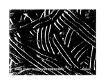
- 10 is an enlarged photograph showing a speaker edge according to Example 4.
- FIG. 6 is a schematic diagram illustrating a fiber entangled body of a speaker edge according to Embodiment 2.
- FIG. 6 is a cross-sectional view illustrating a speaker edge according to a third embodiment.
- 10 is an enlarged photograph showing a speaker edge according to Example 4.
- the speaker edge according to the embodiment of the present invention includes a plate-like fiber entangled body in which at least elastomer fibers are entangled, and the elastomer fiber located on the front surface, back surface, near the front surface or near the back surface of the fiber entangled body has a surface or A flat portion along the back surface is formed.
- the plane portion is formed in the elastomer fiber means that the cross section of the elastomer fiber is formed in an oval shape (such as an oval shape or a rounded rectangular shape) having a longitudinal direction in one direction of the fiber entangled body. Means that.
- at least a part of the side surface of the elastomer fiber in which the flat portion is formed is formed in an oval shape (such as an oval shape or a rounded rectangular shape) whose longitudinal direction is the extending direction of the elastomer fiber.
- the area of the elastomer fiber when the fiber entangled body is viewed in plan can be increased as compared with a fiber entangled body having only the elastomer fiber extending in a columnar shape. Therefore, it becomes difficult for gas to pass through the fiber entangled body in the direction perpendicular to the surface (thickness direction), and the air permeability resistance of the speaker edge can be improved.
- the elastomer fiber is easily deformed, and, for example, by applying heat or pressure to the fiber entangled body, the flat portion can be easily formed, and the air resistance can be improved with a simple configuration.
- the same plane part may be formed not only on the surface of the fiber entangled body, the back surface, the vicinity of the front surface, or the elastomer fiber positioned in the vicinity of the back surface, but also on the elastomer fiber positioned in the center portion in the perpendicular direction.
- the fiber entangled body may have unevenness
- the fiber entangled body has a plastic fiber.
- the Young's modulus of the speaker edge can be improved and good acoustic characteristics can be obtained.
- the mass of the elastomer fiber may be equal to or less than the mass of the plastic fiber.
- the equivalent circle diameter of the cross section of the plastic fiber is preferably smaller than the equivalent circle diameter of the cross section of the elastomer fiber. As a result, the Young's modulus can be prevented from becoming too high.
- the equivalent circle diameter of the cross section means the diameter of a circle having the same area as the cross section. That is, a small equivalent circle diameter of a cross section is synonymous with a small cross sectional area.
- the fiber entangled body includes a plurality of fiber bundles each composed of at least two elastomer fibers, and the plurality of fiber bundles are entangled.
- the plurality of fiber bundles are entangled.
- the elastic modulus may be deteriorated due to light (ultraviolet rays) as an environmental factor, but the fiber entanglement is formed by forming a fiber entangled body with a fiber bundle. A decrease in the elastic modulus of the body can be suppressed.
- the elastomer fiber preferably has a fiber length (length in the extending direction) of 5 mm or less.
- the second layer may be formed of a film.
- the fiber entangled body may have natural fibers. Thereby, the Young's modulus of the speaker edge can be appropriately adjusted, and good acoustic characteristics can be obtained.
- a speaker device includes the speaker edge according to any one of the above, a diaphragm, a frame that supports the diaphragm via the speaker edge, a voice coil, and a magnetic circuit. .
- the speaker device of the present embodiment by improving the air permeability resistance of the edge with a simple configuration, good acoustic characteristics can be obtained and the speaker device can be reduced in cost.
- the edge since the edge includes the fiber entangled body, the entire edge can be reduced in weight, and the ratio of the sound pressure obtained with respect to the power supplied to the speaker device (the efficiency of the speaker device) can be improved. . Therefore, power consumption of the speaker device during sound emission can be suppressed.
- a moving body includes the above-described speaker device, and the speaker device is attached to an attached body.
- the mounted body is, for example, a door body, an instrument panel, a pillar, or the like, and may be a portion suitable for mounting in the moving body.
- the mobile body of the present invention since the power consumption of the speaker device is suppressed as described above, the battery capacity of the mobile body is unlikely to decrease. Therefore, when the moving body is, for example, an electric vehicle including a battery and a motor, the cruising distance is unlikely to be shortened even if music or the like is reproduced by the speaker device.
- FIG. 1 is a plan view showing a speaker edge 1A according to Embodiment 1 of the present invention
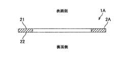
- FIG. 2 is a cross-sectional view taken along line XX of FIG. 1
- FIG. 4 is a schematic view showing the fiber entangled body 2A
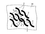
- FIG. 4 is an enlarged plan view showing the fiber entangled body 2A
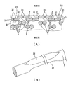
- FIG. 5 is an enlarged sectional view showing the fiber entangled body 2A
- FIG. 6 is a perspective view showing one elastomer fiber 3 constituting 2A
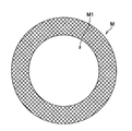
- FIG. 6 is a plan view showing a net M for forming a fiber entangled body 2A
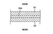
- FIG. 7 shows a fiber entangled body 2A. It is sectional drawing which shows the type
- the speaker edge 1 ⁇ / b> A is configured to be a single layer by a single plate-like fiber entangled body 2 ⁇ / b> A, and has a roll-like cross-sectional shape by a mold or the like, for example. After being formed into a speaker device, it is used for a speaker device (not shown).
- the speaker device is provided, for example, on a vehicle door as a moving body.
- the fiber entangled body 2A is formed in an annular shape in plan view, and a diaphragm (not shown) is provided in the center hole.
- the fiber entangled body 2 ⁇ / b> A is formed by entangled elastomer fibers 3 and plastic fibers 4, and is provided with an additive 5.
- the additive 5 include an ultraviolet absorber and an antioxidant.
- FIG. 4 only the elastomer fiber 3 is shown, and the plastic fiber 4 and the additive 5 are omitted.
- the “front side” of the speaker edge 1A and the fiber entangled body 2A means the sound emission side in the speaker device, and the “back side” means the opposite side.
- the elastomer fiber 3 is an elastic fiber such as an ether-based polyurethane fiber, and its equivalent circle diameter is about 38 to 45 ⁇ m and the melting temperature is 200 ° C. or less. Moreover, the fiber length (length in the extending direction) of the elastomer fiber 3 is 5 mm or less.
- the fiber entangled body 2A two elastomer fibers 3 are in close contact to form a fiber bundle 30, and a plurality of fiber bundles 30 are entangled. As shown in FIG. 5 (A), on the front side and the back side of the elastomer fiber 3 located on the front surface 21 (or the vicinity of the front surface 21) of the fiber entangled body 2A, a flat portion 31 along the front surface 21 is formed.
- the cross section of these elastomer fibers 3 is formed in an oval shape (oval shape, rounded rectangular shape) having a long diameter in one direction in the plane of the fiber entangled body 2A.
- the width of the flat portion 31 (the horizontal dimension in FIG. 5) is, for example, 40 to 50 ⁇ m.
- FIG. 5B shows a single elastomer fiber 3 on which the flat surface portion 31 is formed.
- the elastomer fiber 3 is formed with a flat portion 31 so that a part of the side surface of the elastomer fiber 3 is flat, and the flat surface portion 31 has an extension direction of the elastomer fiber as a longitudinal direction on the side surface of the elastomer fiber 3. It is formed in an oval shape (such as an oval shape or a rounded rectangular shape).
- the planar portion 31 is formed on the elastomer fiber 3 positioned closest to the front surface side and the elastomer fiber 3 positioned next to the front surface side.
- the elastomer fiber 3 may be formed with a flat portion, and it is sufficient that the flat portion is formed at least on the elastomer fiber 3 positioned on the most surface side.
- FIG. 5 for convenience of explanation, it is schematically illustrated that the elastomer fibers 3 are regularly arranged, but actually the elastomer fibers 3 are randomly arranged.
- the flat portion 31 is formed on the elastomer fiber 3 on the back surface 22 side of the fiber entangled body 2A as well as on the front surface 21 side.
- the ether-based polyurethane fiber as the elastomer fiber 3 is easily deteriorated by breaking the ether bond by ultraviolet rays as an environmental factor, and the ether-based polyurethane fiber elastic modulus decreases due to the deterioration.
- the plastic fiber 4 is, for example, a polyethylene fiber, a polypropylene fiber, a polyethylene terephthalate fiber, a polyamide fiber, or the like, and is a fiber having a higher Young's modulus than the elastomer fiber 3, and a fiber whose cross-sectional shape is less likely to be deformed than the elastomer fiber 3. is there.
- the plastic fiber 4 has an equivalent circle diameter of, for example, 4 to 10 ⁇ m, and a glass transition temperature of, for example, 250 ° C. or more. If the equivalent circle diameter of the plastic fiber 4 is too small, the speaker edge may easily absorb water due to capillary action when water enters the speaker device.
- the equivalent circle diameter of the plastic fiber 4 is too large, the Young's modulus of the entire speaker edge becomes too high, and the acoustic characteristics in the low frequency band may be deteriorated. As a decrease in acoustic characteristics in the low frequency band, the lowest resonance frequency is generated on the high frequency band side in the low frequency band.
- the ratio of the mass of the elastomer fiber 3 and the mass of the plastic fiber 4 is, for example, 90:10 to 50:50, and the mass of the elastomer fiber 3 is larger. .
- the Young's modulus of the speaker edge can be adjusted.
- the additive 5 is, for example, an ultraviolet absorber and is dispersed at an appropriate density in the fiber entangled body 2A.
- the fiber entangled body 2A with the ultraviolet absorbent as the additive, it is possible to suppress the elastomer fiber 3 from being deteriorated by the ultraviolet rays and the elastic modulus of the fiber entangled body 2A from being lowered.
- the elastomer fiber 3, the plastic fiber 4, and the additive 5 are dispersed in an appropriate solvent (for example, water) to obtain a stock solution, and a net M as shown in FIG. 6 is immersed in a tank that stores the stock solution.
- an appropriate solvent for example, water
- the mesh M is formed in an annular shape like the fiber entangled body 2A, and the mesh has an appropriate fineness.
- the central portion M1 of the net M may be a hole or a plate. In the case where the central portion M1 is a plate, it is preferable to have water repellency so that the stock solution does not remain on the plate during paper making.
- the elastomer fiber 3, the plastic fiber 4 and the additive 5 By lifting the net M immersed in the tank, the elastomer fiber 3, the plastic fiber 4 and the additive 5 remain on it. By heating the mesh M from above (front side) and below (back side) of the mesh M or sucking water from below, the elastomer fibers 3, the plastic fibers 4 and the additive 5 are dried, and before deformation.
- the fiber entangled body 20A is formed.
- the elastomer fiber 3 extends in a columnar shape and does not have a flat portion.
- the fiber entangled body 20A before deformation is sandwiched from both the front and back surfaces by a pair of molds D1 and D2, and heated and pressed.
- the heating temperature at this time is higher than the glass transition temperature of the elastomer fiber 3 and lower than the melting temperature, and may be higher or lower than the glass transition temperature of the plastic fiber 4.
- the elastomer fiber 3 located in the vicinity of the front surface 21 and the back surface 22 of the fiber entangled body 20 ⁇ / b> A is deformed, and the flat portion 31 is formed.
- the fiber entangled body 2A is formed, and the manufacture of the speaker edge 1A is completed.
- the fiber length of the elastomer fiber 3 is 5 mm or less, the elastomer fiber 3 is prevented from protruding from the outer periphery of the molds D1 and D2, and the elastomer fiber 3 from the desired outer shape of the speaker edge 1A is reduced.
- the protrusion can be suppressed.
- the fiber entangled body 20A Before the fiber entangled body 20A is sandwiched between the pair of molds D1 and D2, the fiber entangled body 20A may not be completely dried, and the fibers are heated and pressed using the pair of molds D1 and D2. The entangled body 20A may be dried.
- the planar portion 31 is formed on the elastomer fiber 3, so that the elastomer fiber 3 when the fiber entangled body 2 ⁇ / b> A is viewed in plan compared to a fiber entangled body having only the elastomer fiber extending in a columnar shape.
- the area can be increased. Therefore, it becomes difficult for gas to pass in the direction perpendicular to the fiber entangled body 2A, and the air resistance of the speaker edge 1A can be improved.
- the planar portion 31 can be formed on the elastomer fiber 3, and the air resistance can be improved with a simple configuration.
- the fiber entangled body 2A has the plastic fiber 4, and the mass of the elastomer fiber 3 is smaller than the mass of the plastic fiber 4, so that the Young's modulus is moderately improved and is not excessively high. Acoustic characteristics can be obtained.
- the equivalent circle diameter of the cross section of the plastic fiber 4 is smaller than the equivalent circle diameter of the cross section of the elastomer fiber 3, the Young's modulus can be prevented from becoming too high.
- the fiber entangled body 2A includes a plurality of fiber bundles 30 composed of two elastomer fibers 3, even if one elastomer fiber 3 is degraded by ultraviolet rays, the other elastomer fiber 3 is not degraded. Moreover, the fall of the elastic modulus of 2 A of fiber entanglement bodies can be suppressed.
- FIG. 8 is a schematic diagram illustrating the fiber entangled body 2B of the speaker edge according to the second embodiment.
- the ratio of the mass of the elastomer fiber 3 and the mass of the plastic fiber 4 is, for example, 49:51 to 10:90, and the mass of the elastomer fiber 3 is smaller. .
- the plastic fiber 4 having a relatively small equivalent circle diameter (in particular, the plastic fiber 4 having a smaller equivalent circle diameter than the elastomer fiber 3) is used for the fiber entangled body 2B of the speaker edge.
- FIG. 9 is a cross-sectional view illustrating the speaker edge 1 ⁇ / b> C according to the third embodiment.
- the speaker edge 1C includes a first layer L1 formed of the fiber entangled body 2C and a second layer L2 stacked on the surface side of the first layer L1.
- the fiber entangled body 2C has, for example, the same configuration as the fiber entangled body 2A of Example 1 or the fiber entangled body 2B of Example 2. That is, the mass ratio between the elastomer fiber 3 and the plastic fiber 4 in the fiber entangled body 2C may be set appropriately.
- the second layer L2 is constituted by a second fiber entangled body 5 in which fibers different from the elastomer fiber 3 are entangled.
- the 2nd fiber entangled body 5 shall be formed with the fiber similar to the natural fiber, such as a pulp, and the plastic fiber 4, for example.
- the second fiber entangled body 5 may be provided with an additive such as an ultraviolet absorber.
- the second layer L2 only needs to have a thickness that makes it difficult to transmit ultraviolet rays to the back side by reflecting or absorbing ultraviolet rays irradiated from the front side.
- the first layer L1 and the second layer L2 may be formed integrally by making one so as to overlap the other, or may be bonded after making each independently.
- the second layer L2 is not limited to the one constituted by the second fiber entangled body 5, and may be constituted by a film.
- the film may be made of, for example, a vinyl chloride-based or polyamide-based material, and is preferably light and has an appropriate Young's modulus.
- a film shall be affixed on the fiber entanglement body 2C.
- the second layer L2 is overlapped on the surface side of the first layer L1, so that the first layer L1 is protected from ultraviolet rays irradiated from the surface side, and the fiber entanglement constituting the first layer L1 It is possible to make the elastomer fiber 3 of the body 2C difficult to deteriorate and to suppress a decrease in the elastic modulus of the fiber entangled body 2C.
- the present invention is not limited to the first to third embodiments, but includes other configurations and the like that can achieve the object of the present invention.
- the following modifications are also included in the present invention.
- the fiber entangled bodies 2A to 2C have the elastomer fibers 3, the plastic fibers 4, and the additive 5.
- the fiber entangled body is one in which at least the elastomer fibers 3 are entangled.
- the plastic fiber 4 and the additive 5 may be omitted.
- the equivalent circle diameter of the cross section of the plastic fiber 4 is smaller than the equivalent circle diameter of the cross section of the elastomer fiber 3, but these equivalent circle diameters are appropriately set according to the required Young's modulus. Any value is acceptable.
- the equivalent circle diameter of the plastic fiber may be greater than or equal to the equivalent circle diameter of the elastomer fiber.
- the fiber bundle 30 is constituted by the two elastomer fibers 3, but the fiber bundle may be constituted by three or more elastomer fibers 3.
- the fiber bundle is not configured. May be.
- the planar portion 31 is formed on the elastomer fiber 3 located in the vicinity of the front surface 21 and the back surface 22 of the fiber entangled body 2A.
- the planar portion is an elastomer fiber located near the surface. 3 may be formed only on the elastomeric fiber 3, or may be formed only on the elastomer fiber 3 located in the vicinity of the back surface.
- the plane part shall be formed in both the surface side and back surface side of the elastomer fiber 3, the plane part may be formed only in the surface side, and the back surface side It may be formed only.
- the fiber length of the elastomer fiber 3 is 5 mm or less.
- the fiber length of the elastomer fiber may be an appropriate length according to the properties of the elastomer fiber, the manufacturing method, and the like. .
- the elastomer fibers are not easily entangled during paper making and easily dispersed, or if the elastomer fibers are difficult to protrude from the outer periphery of the mold during heating and pressurization, use an elastomer fiber having a fiber length longer than 5 mm. Also good.
- ether-based polyurethane fibers that are easily deteriorated by ultraviolet rays are exemplified as the elastomer fibers 3.
- the material is not limited to ultraviolet rays, for example, other than water, temperature, and the like.
- the second layer L2 has an appropriate material, thickness, etc. according to environmental factors that cause degradation of the elastomer fiber. It only has to be.
- a third layer for protecting the first layer from the environmental factor may be provided on the back side of the first layer.
- the fiber entangled body 2A in Example 1 is a combination of two or more fibers of a fiber having a large length, a fiber having a small length, a fiber having a large equivalent circle diameter in cross section, or a fiber having a small equivalent circle diameter in cross section.
- Such two or more fibers may be natural fibers such as pulp.
- an elastomer fiber or a plastic fiber may be added in order to adjust the rigidity of the edge.
- the ratio of the mass of the two or more fibers to the mass of the elastomer fiber or the plastic fiber is 90:10 to 50:50, and the mass of the two or more fibers is larger.
- fibers examples include wood pulp fibers such as sulfite pulp and kraft pulp, non-wood pulp fibers such as bamboo and straw, chemical fibers and synthetic fibers composed of rayon, nylon, vinylon, polyester, acrylic, silk and wool Animal fibers such as manila hemp and cotton, organic fibers composed of graphite, mineral fibers composed of silicon carbide, etc. (glass fibers, carbon fibers, ceramic fibers), minerals composed of basalt, etc. Examples include fibers. Examples of natural fibers here include wood pulp fibers, non-wood pulp fibers, plant fibers, and animal fibers.
- Example 1 the paper product was formed into a plate shape and then formed into a roll shape with a mold. At the stage of forming the paper product, the paper product was formed using a net having a roll-shaped cross section, and dried. It is also possible to do only with the process.
- Example 4 is a fiber entangled body composed of only polyurethane fibers having a fiber length of 5 mm as elastomer fibers, and a flat portion is formed on the elastomer fibers by pressurization and heating as described above.
- a fiber entangled body is composed of the same polyurethane fiber as in Example 4 as an elastomer fiber and a polyamide fiber having a fiber diameter of 0.9 T (decitex) and a fiber length of 5 mm as a plastic fiber, as described above.
- a flat portion is formed on the elastomer fiber by pressurization and heating.
- the mass ratio of polyurethane fiber to polyamide fiber is 8: 2.
- the fiber entangled body is composed of only polyurethane fibers having a fiber length of 5 mm as elastomer fibers, and no flat portion is formed on the elastomer fibers.
- FIG. 10 shows an enlarged photograph of the surface of the speaker edge of Example 4 as described above.
- the enlarged photograph in FIG. 10 is taken with an electron microscope, and the photographing conditions are shown in the lower left part of the photograph.
- This photo was taken at a magnification of 150 times, but the ratio of the dimensions to the original size in FIG. 10 is different from this magnification.
- the dimensions of each part are shown in the scale bar at the lower right of the photo. As shown.
- the air permeability resistance of the speaker edge was evaluated by the test method described in JISP8117: 2009.
- the respective air resistances were 568 sec in Example 4, 62 sec in Example 5, and 1 sec in Comparative Example 1. That is, good values were obtained with the speaker edges of Examples 4 and 5 in which the flat portion was formed on the elastomer fiber, and the air resistance was insufficient with the speaker edge of Comparative Example 1 in which the flat portion was not formed. It became the value.
- the edge for a speaker of Example 4 which did not contain polyamide fiber as a plastic fiber was particularly good.
- Example 4 the Young's modulus of the speaker edge was evaluated.
- the respective Young's moduli were 3.68 ⁇ 10 7 N / m 2 in Example 4 and 7.99 ⁇ 10 7 N / m 2 in Example 5. That is, the Young's modulus could be improved by including the polyamide fiber as the plastic fiber in the speaker edge of Example 5.
Landscapes
- Engineering & Computer Science (AREA)
- Physics & Mathematics (AREA)
- Acoustics & Sound (AREA)
- Signal Processing (AREA)
- Multimedia (AREA)
- Diaphragms For Electromechanical Transducers (AREA)
Abstract
簡単な構成で透気抵抗度を向上させることができるスピーカ用エッジを提供する。エラストマー繊維(3)に平面部(31)が形成されていることで、円柱状に延びるエラストマー繊維のみを有する繊維交絡体と比較して、繊維交絡体(2A)を平面視した際のエラストマー繊維(3)の面積を大きくすることができる。従って、繊維交絡体(2A)に対して面直方向に気体が通過しにくくなり、スピーカ用エッジ(1A)の透気抵抗度を向上させることができる。また、繊維交絡体(2A)を加熱及び加圧することにより、エラストマー繊維(3)に平面部(31)を形成することができ、簡単な構成で透気抵抗度を向上させることができる。
Description
本発明は、繊維交絡体を備えたスピーカ用エッジに関する。
従来、ポリウレタンエラストマー繊維と紙パルプとを有するとともに抄造によって形成されるスピーカ用エッジが提案されている(例えば、特許文献1参照)。特許文献1に記載された従来のスピーカ用エッジでは、ポリウレタンエラストマー繊維によって紙パルプの隙間を埋めることで気密性の向上(即ち、JISP8117:2009で定義される透気抵抗度の向上)を図っている。尚、透気抵抗度とは、単位面積及び単位圧力差当たり、規定された体積の空気が透過するのに要する時間であり、透気抵抗度が高いほど気体が通過しにくい。
しかしながら、特許文献1に記載されたスピーカ用エッジにおいてさらに透気抵抗度を向上させるためには、ポリウレタンエラストマー繊維の含有量を多くする必要がある。ポリウレタンエラストマー繊維の含有量を多くすると、スピーカ用エッジの重量が大きくなり、その結果、スピーカ装置全体の重量が大きくなってしまったり、スピーカ用エッジのヤング率が所望の値よりも小さくなってしまったりする。
したがって、本発明の課題は、簡単な構成で透気抵抗度を向上させることができるスピーカ用エッジを提供することが一例として挙げられる。
前述した課題を解決し目的を達成するために、請求項1に記載の本発明のスピーカ用エッジは、少なくともエラストマー繊維が交絡した繊維交絡体を備え、前記繊維交絡体における表面又は裏面に位置する前記エラストマー繊維には、該表面又は該裏面に沿った平面部が形成されていることを特徴としている。
以下、本発明の実施形態を説明する。本発明の実施形態に係るスピーカ用エッジは、少なくともエラストマー繊維が交絡した板状の繊維交絡体を備え、繊維交絡体における表面、裏面、表面近傍又は裏面近傍に位置するエラストマー繊維には、表面又は裏面に沿った平面部が形成されている。
エラストマー繊維に平面部が形成されているとは、エラストマー繊維の断面が繊維交絡体の面内の一方向を長手方向とするオーバル形状(長円形状や角丸長方形状など)に形成されていることを意味する。また、平面部が形成されたエラストマー繊維は、その側面の少なくとも一部が、エラストマー繊維の延在方向を長手方向とするオーバル形状(長円形状や角丸長方形状など)に形成されている。このようなエラストマー繊維を用いることで、円柱状に延びるエラストマー繊維のみを有する繊維交絡体と比較して、繊維交絡体を平面視した際のエラストマー繊維の面積を大きくすることができる。従って、繊維交絡体に対して面直方向(厚さ方向)に気体が通過しにくくなり、スピーカ用エッジの透気抵抗度を向上させることができる。
また、エラストマー繊維は変形させやすく、繊維交絡体に対して例えば熱や圧力を加えることにより、容易に平面部を形成することができ、簡単な構成で透気抵抗度を向上させることができる。尚、繊維交絡体の表面、裏面、表面近傍又は裏面近傍に位置するエラストマー繊維だけでなく、面直方向中央部に位置するエラストマー繊維にも、同様の平面部が形成されていてもよい。また、繊維交絡体は表面及び裏面に凹凸を有していてもよい。
繊維交絡体は、可塑性繊維を有することが好ましい。それにより、スピーカ用エッジのヤング率を向上させ、良好な音響特性を得ることができる。
繊維交絡体において、エラストマー繊維の質量が可塑性繊維の質量以下であってもよいし、大きくてもよい。エラストマー繊維と可塑性繊維との質量比を適宜に設定することにより、ヤング率を調節し、良好な音響特性を得ることができる。
可塑性繊維の断面の円相当径は、エラストマー繊維の断面の円相当径よりも小さいことが好ましい。それにより、ヤング率が高くなりすぎてしまわないようにすることができる。尚、断面の円相当径とは、その断面と面積が等しい円の直径を意味する。即ち、断面の円相当径が小さいことと、断面積が小さいこととは同義である。
繊維交絡体は、それぞれ少なくとも2本のエラストマー繊維で構成される繊維束を複数備え、複数の繊維束が交絡していることが好ましい。それにより、環境因子によって一部のエラストマー繊維が劣化しても、繊維束を構成する複数のエラストマー繊維のうち劣化していないエラストマー繊維があれば、繊維交絡体の特性の変化を抑制することができる。例えば、エラストマー繊維がポリウレタン繊維である場合、環境因子としての光(紫外線)によって劣化して弾性率が低下してしまうことがあるものの、繊維束で繊維交絡体を形成していることで繊維交絡体の弾性率の低下を抑制することができる。
エラストマー繊維は、その繊維長(延在方向における長さ)が5mm以下であることが好ましい。それにより、抄造法によってスピーカ用エッジを製造する際に、エラストマー繊維同士が絡みにくく、且つ、分散しやすくなる。また、抄造後に繊維交絡体を金型によって加熱及び加圧する際に、エラストマー繊維が金型の外周からはみ出すことを抑制し、スピーカ用エッジの所望の外形形状からエラストマー繊維がはみ出すことを抑制することができる。一方、エラストマー繊維の繊維長が5mmよりも長いと、エラストマー繊維同士が絡まりやすく、且つ、分散しにくくなってしまう。
繊維交絡体により形成された第1層と、第1層の表面側に重ねられた第2層と、を備え、第2層は、エラストマー繊維とは異なる繊維が交絡した第2繊維交絡体により形成されていてもよい。また、第2層は、フィルムにより形成されていてもよい。それにより、第1の層の表面側に重ねられた第2の層により、第1の層を環境因子から保護することができ、繊維交絡体の特性の変化を抑制することができる。
また、繊維交絡体が天然繊維を有していてもよい。それにより、スピーカ用エッジのヤング率を適宜に調節し、良好な音響特性を得ることができる。
本発明の実施形態に係るスピーカ装置は、上記いずれかに記載のスピーカ用エッジと、振動板と、スピーカ用エッジを介して振動板を支持するフレームと、ボイスコイルと、磁気回路と、を備える。本実施形態のスピーカ装置によれば、エッジの透気抵抗度を簡単な構成で向上させることにより、良好な音響特性を得ることができるとともに、スピーカ装置を低コスト化することができる。また、エッジが繊維交絡体を備えることで、エッジ全体を軽量化することができ、スピーカ装置に供給される電力に対して得られる音圧の割合(スピーカ装置の効率)を向上させることができる。従って、音放射時のスピーカ装置の消費電力を抑制することができる。
本発明の実施形態に係る移動体は、上記のスピーカ装置を備え、スピーカ装置が被取付体に取り付けられる。被取付体は、例えば、扉体やインストルメントパネル、ピラー等であって、移動体のうち取付に適した部分であればよい。本発明の移動体によれば、上記のようにスピーカ装置の消費電力が抑制されていることで、移動体のバッテリの容量が減りにくい。従って、移動体が例えばバッテリ及びモータを備える電気自動車である場合、スピーカ装置によって音楽等を再生しても航続距離が短くなりにくい。
以下、本発明の実施例について具体的に説明する。なお、実施例2、3においては、実施例1で説明する構成部材と同じ構成部材及び同様な機能を有する構成部材には、実施例1と同じ符号を付すとともに説明を省略する。
[実施例1]
図1は、本発明の実施例1に係るスピーカ用エッジ1Aを示す平面図であり、図2は、図1のX-X線に沿う断面図であり、図3は、スピーカ用エッジ1Aの繊維交絡体2Aを示す模式図であり、図4は、繊維交絡体2Aを拡大して示す平面図であり、図5は、繊維交絡体2Aを拡大して示す断面図、及び、繊維交絡体2Aを構成する一本のエラストマー繊維3を示す斜視図であり、図6は、繊維交絡体2Aを形成するための網Mを示す平面図であり、図7は、繊維交絡体2Aを形成するための型D1、D2を示す断面図である。
図1は、本発明の実施例1に係るスピーカ用エッジ1Aを示す平面図であり、図2は、図1のX-X線に沿う断面図であり、図3は、スピーカ用エッジ1Aの繊維交絡体2Aを示す模式図であり、図4は、繊維交絡体2Aを拡大して示す平面図であり、図5は、繊維交絡体2Aを拡大して示す断面図、及び、繊維交絡体2Aを構成する一本のエラストマー繊維3を示す斜視図であり、図6は、繊維交絡体2Aを形成するための網Mを示す平面図であり、図7は、繊維交絡体2Aを形成するための型D1、D2を示す断面図である。
スピーカ用エッジ1Aは、図1、2に示すように、1枚の板状の繊維交絡体2Aによって単層となるように構成されており、例えば金型等によってロール状の断面形状を有するように成形された後に、図示しないスピーカ装置に用いられる。このスピーカ装置は、例えば移動体としての車両の扉体等に設けられる。
繊維交絡体2Aは、平面視円環状に形成されており、その中央の孔に図示しない振動板が設けられる。繊維交絡体2Aは、図3、4に示すように、エラストマー繊維3及び可塑性繊維4が交絡して形成されているとともに、添加材5が設けられている。添加剤5の例として紫外線吸収剤や酸化防止剤等が挙げられる。尚、図4ではエラストマー繊維3のみを図示し、可塑性繊維4及び添加材5を省略している。また、スピーカ用エッジ1A及び繊維交絡体2Aの「表面側」は、スピーカ装置における音放射側を意味し、「裏面側」はその反対側を意味する。
エラストマー繊維3は、例えばエーテル系ポリウレタン繊維等の弾性を有する繊維であって、その円相当径が38~45μm程度とされ、溶融温度が200℃以下となっている。また、エラストマー繊維3の繊維長(延在方向における長さ)は、5mm以下となっている。繊維交絡体2Aにおいて、2本のエラストマー繊維3が密着して繊維束30を構成しており、複数の繊維束30同士が交絡している。図5(A)に示すように、繊維交絡体2Aの表面21(又は表面21の近傍)に位置するエラストマー繊維3の表面側及び裏面側には、表面21に沿った平面部31が形成されている。即ち、これらのエラストマー繊維3の断面は、繊維交絡体2Aの面内の一方向を長径とするオーバル形状(長円形状、角丸長方形状)に形成されている。平面部31の幅(図5の左右方向寸法)は、例えば40~50μmであるものとする。
平面部31が形成された一本のエラストマー繊維3を代表して図5(B)に示す。このエラストマー繊維3は、その側面のうち一部が平坦となるように平面部31が形成されており、平面部31は、エラストマー繊維3の側面において、エラストマー繊維の延在方向を長手方向とするオーバル形状(長円形状や角丸長方形状など)に形成されている。
尚、図5(A)では、最も表面側に位置するエラストマー繊維3及びその次に表面側に位置するエラストマー繊維3に平面部31が形成されているものとしたが、これらよりも裏面側のエラストマー繊維3にも平面部が形成されていてもよく、少なくとも最も表面側に位置するエラストマー繊維3に平面部が形成されていればよい。また、図5では説明の都合上、エラストマー繊維3が規則的に並んでいるように模式的に記載したが、実際にはエラストマー繊維3はランダムに並んでいる。さらに、繊維交絡体2Aの裏面22側においても、表面21側と同様にエラストマー繊維3に平面部31が形成されているものとする。
エラストマー繊維3としてのエーテル系ポリウレタン繊維は、環境因子としての紫外線によってエーテル結合が切断されて劣化しやすく、劣化によってエーテル系ポリウレタン繊維弾性率が低下する。
可塑性繊維4は、例えばポリエチレン繊維やポリプロピレン繊維、ポリエチレンテレフタレート繊維、ポリアミド繊維等であって、エラストマー繊維3よりも高いヤング率を有する繊維であり、エラストマー繊維3よりも断面形状が変形しにくい繊維でもある。また、可塑性繊維4は、円相当径が例えば4~10μmとされ、ガラス転移温度が例えば250℃以上となっている。可塑性繊維4の円相当径が小さすぎると、スピーカ装置に水が浸入した際に毛細管現象によってスピーカ用エッジが水を吸収しやすくなってしまう場合がある。一方、可塑性繊維4の円相当径が大きすぎると、スピーカ用エッジ全体のヤング率が高くなりすぎてしまい、低音帯域における音響特性が低下してしまうことがある。低音帯域における音響特性の低下としては、最低共振周波数が低音帯域内における高音帯域側に生じること等が挙げられる。
本実施例の繊維交絡体2Aにおいて、エラストマー繊維3の質量と、可塑性繊維4の質量と、の比は、例えば90:10~50:50となっており、エラストマー繊維3の質量の方が大きい。エラストマー繊維3の質量を可塑性繊維4の質量よりも大きくすることで、スピーカ用エッジのヤング率を調節することができる。
添加材5は、例えば紫外線吸収剤であって、繊維交絡体2A中に適宜な密度で分散している。添加材としての紫外線吸収剤が繊維交絡体2Aに設けられていることで、紫外線によってエラストマー繊維3が劣化して繊維交絡体2Aの弾性率が低下してしまうことを抑制することができる。
以下、抄造法によってスピーカ用エッジ1Aを製造する方法について説明する。まず、エラストマー繊維3と可塑性繊維4と添加材5とを適宜な溶媒(例えば水)に分散させて原液とし、この原液を収容するタンク内に、図6に示すような網Mを浸漬させる。このとき、エラストマー繊維3の繊維長が5mm以下であることで、エラストマー繊維3同士が絡みにくく、且つ、分散しやすくなる。網Mは、繊維交絡体2Aと同様に円環状に形成され、その網目は適宜な細かさを有している。尚、網Mの中央部M1は、孔となっていてもよいし、板となっていてもよい。中央部M1が板となる場合、抄造時に原液が板の上に残らないように撥水性を有していることが好ましい。
タンク内に浸漬した網Mを持ち上げることで、その上にエラストマー繊維3と可塑性繊維4と添加材5とが残る。この網Mを網Mの上方(表面側)及び下方(裏面側)から加熱したり下方から水を吸引したりすることにより、エラストマー繊維3と可塑性繊維4と添加材5と乾燥させ、変形前の繊維交絡体20Aを形成する。この繊維交絡体20Aでは、エラストマー繊維3は、円柱状に延びており、平面部を有していない。
次に、図7に示すように、変形前の繊維交絡体20Aを一対の金型D1、D2によって表面及び裏面の両面から挟み込み、加熱及び加圧する。このときの加熱温度は、エラストマー繊維3のガラス転移温度よりも高く溶融温度よりも低くするものとし、可塑性繊維4のガラス転移温度より高くてもよいし低くてもよい。これにより、繊維交絡体20Aの表面21及び裏面22近傍に位置するエラストマー繊維3が変形し、平面部31が形成される。このように繊維交絡体2Aが形成され、スピーカ用エッジ1Aの製造が完了する。このとき、エラストマー繊維3の繊維長が5mm以下であることで、エラストマー繊維3が金型D1、D2の外周からはみ出すことを抑制し、スピーカ用エッジ1Aの所望の外形形状からのエラストマー繊維3のはみ出しを抑制することができる。尚、一対の金型D1、D2によって繊維交絡体20Aを挟む前に、繊維交絡体20Aは完全に乾燥していなくてもよく、一対の金型D1、D2を用いた加熱及び加圧によって繊維交絡体20Aを乾燥させてもよい。
上記の構成により、エラストマー繊維3に平面部31が形成されていることで、円柱状に延びるエラストマー繊維のみを有する繊維交絡体と比較して、繊維交絡体2Aを平面視した際のエラストマー繊維3の面積を大きくすることができる。従って、繊維交絡体2Aに対して面直方向に気体が通過しにくくなり、スピーカ用エッジ1Aの透気抵抗度を向上させることができる。また、繊維交絡体2Aを加熱及び加圧することにより、エラストマー繊維3に平面部31を形成することができ、簡単な構成で透気抵抗度を向上させることができる。
また、繊維交絡体2Aが可塑性繊維4を有するとともに、エラストマー繊維3の質量の方が可塑性繊維4の質量よりも小さいことで、ヤング率を適度に向上させるとともに高くなりすぎないようにし、良好な音響特性を得ることができる。
また、可塑性繊維4の断面の円相当径が、エラストマー繊維3の断面の円相当径よりも小さいことで、ヤング率が高くなりすぎてしまわないようにすることができる。
また、繊維交絡体2Aが2本のエラストマー繊維3で構成される繊維束30を複数備えることで、紫外線によって一方のエラストマー繊維3が劣化しても、他方のエラストマー繊維3が劣化していなければ、繊維交絡体2Aの弾性率の低下を抑制することができる。
[実施例2]
図8は、実施例2に係るスピーカ用エッジの繊維交絡体2Bを示す模式図である。本実施例の繊維交絡体2Bにおいて、エラストマー繊維3の質量と、可塑性繊維4の質量と、の比は、例えば49:51~10:90となっており、エラストマー繊維3の質量の方が小さい。
図8は、実施例2に係るスピーカ用エッジの繊維交絡体2Bを示す模式図である。本実施例の繊維交絡体2Bにおいて、エラストマー繊維3の質量と、可塑性繊維4の質量と、の比は、例えば49:51~10:90となっており、エラストマー繊維3の質量の方が小さい。
本実施例では、円相当径が比較的小さい可塑性繊維4(特にエラストマー繊維3よりも円相当径が小さい可塑性繊維4)をスピーカ用エッジの繊維交絡体2Bに用いている。このような構成により、スピーカ用エッジのヤング率を所望の大きさに調節しつつ、スピーカ用エッジの耐久力を向上させることができる。
[実施例3]
図9は、実施例3に係るスピーカ用エッジ1Cを示す断面図である。スピーカ用エッジ1Cは、繊維交絡体2Cで形成された第1層L1と、第1層L1の表面側に重ねられた第2層L2と、を備える。
図9は、実施例3に係るスピーカ用エッジ1Cを示す断面図である。スピーカ用エッジ1Cは、繊維交絡体2Cで形成された第1層L1と、第1層L1の表面側に重ねられた第2層L2と、を備える。
繊維交絡体2Cは、例えば、実施例1の繊維交絡体2A又は実施例2の繊維交絡体2Bと同様の構成を有しているものとする。即ち、繊維交絡体2Cにおけるエラストマー繊維3と可塑性繊維4との質量比は適宜に設定されていればよい。
第2層L2は、エラストマー繊維3とは異なる繊維が交絡した第2繊維交絡体5によって構成されている。第2繊維交絡体5は、例えばパルプ等の天然繊維や、可塑性繊維4と同様の繊維によって形成されているものとする。また、第2繊維交絡体5には、紫外線吸収剤等の添加材が設けられていてもよい。第2層L2は、表側から照射された紫外線を反射したり吸収したりすることにより、紫外線を裏側まで透過しにくいような厚さを有していればよい。
第1層L1と第2層L2とは、一方を抄造した後に他方を重ねるように抄造することで一体的に形成されてもよいし、それぞれを独立に抄造した後に貼り合わされてもよい。
また、第2層L2は、第2繊維交絡体5によって構成されたものに限定されず、フィルムで構成されていてもよい。フィルムは、例えば塩化ビニル系やポリアミド系の材料によって形成されたものであればよく、軽量且つ適宜なヤング率を有するものであることが好ましい。フィルムは、繊維交絡体2Cに貼り付けられるものとする。
上記の構成により、第1層L1の表面側に第2層L2が重ねられていることで、表面側から照射される紫外線から第1層L1を保護し、第1層L1を構成する繊維交絡体2Cのエラストマー繊維3を劣化しにくくし、繊維交絡体2Cの弾性率の低下を抑制することができる。
なお、本発明は、前記実施例1~3に限定されるものではなく、本発明の目的が達成できる他の構成等を含み、以下に示すような変形等も本発明に含まれる。
例えば、前記実施例1~3では、繊維交絡体2A~2Cがエラストマー繊維3と可塑性繊維4と添加材5とを有するものとしたが、繊維交絡体は、少なくともエラストマー繊維3が交絡したものであればよく、可塑性繊維4及び添加材5は省略されていてもよい。
また、前記実施例1では、可塑性繊維4の断面の円相当径がエラストマー繊維3の断面の円相当径よりも小さいものとしたが、これらの円相当径は必要なヤング率に応じた適宜な値であればよい。例えば、高音用スピーカ装置に用いられるようなヤング率が高いスピーカ用エッジを形成したい場合、可塑性繊維の円相当径をエラストマー繊維の円相当径以上としてもよい。
また、前記実施例1では、2本のエラストマー繊維3によって繊維束30が構成されるものとしたが、3本以上のエラストマー繊維3によって繊維束が構成されていてもよい。また、エラストマー繊維3が環境因子によって劣化しにくい性質を有する場合や、実施例3のように第2層L2によってエラストマー繊維3が充分に保護されている場合には、繊維束は構成されていなくてもよい。
また、前記実施例1では、繊維交絡体2Aの表面21及び裏面22近傍に位置するエラストマー繊維3に平面部31が形成されているものとしたが、平面部は、表面近傍に位置するエラストマー繊維3のみに形成されていてもよいし、裏面近傍に位置するエラストマー繊維3のみに形成されていてもよい。また、前記実施例1では、エラストマー繊維3の表面側及び裏面側の両方に平面部が形成されているものとしたが、平面部は、表面側のみに形成されていてもよいし、裏面側のみに形成されていてもよい。
また、前記実施例1では、エラストマー繊維3の繊維長が5mm以下であるものとしたが、エラストマー繊維の繊維長は、エラストマー繊維の性質や製造方法等に応じた適宜な長さであればよい。例えば、抄造時にエラストマー繊維同士が絡みにくく分散しやすい場合や、金型による加熱及び加圧時にエラストマー繊維が金型の外周からはみ出しにくい場合には、繊維長が5mmよりも長いエラストマー繊維を用いてもよい。
また、前記実施例1では、エラストマー繊維3として紫外線によって劣化しやすいエーテル系ポリウレタン繊維を例示したが、エラストマー繊維が他の材料によって形成されている場合、紫外線に限らず例えば水や温度等の他の環境因子によって劣化する可能性がある。実施例3のように第2層L2によって第1層L1を保護する場合、第2層L2は、エラストマー繊維の劣化の要因となる環境因子に応じて、適宜な材質や厚さ等を有していればよい。また、スピーカ用エッジの裏面側も環境因子によって劣化し得る場合には、第1層を環境因子から保護する第3層が第1層の裏面側に設けられてもよい。
また、実施例1における繊維交絡体2Aを、長さが大きい繊維、長さが小さい繊維、断面の円相当径が大きい繊維、又は断面における円相当径が小さい繊維のうち2以上の繊維を組み合わせることによって形成しても構わない。このような2以上の繊維として、例えばパルプ等の天然繊維であっても構わない。また、2以上の繊維の他に、エッジの剛性を調整するために、エラストマー繊維又は可塑性繊維を加えても構わない。2以上の繊維の質量と、エラストマー繊維又は可塑性繊維の質量と、の比は、90:10~50:50となっており、2以上の繊維の質量の方が大きい。このような繊維交絡体でエッジを形成することにより、エッジの強度、耐久性を高めることができる。
繊維の例として、サルファイトパルプやクラフトパルプなどの木材パルプ繊維、竹やワラ等の非木材パルプ繊維、レーヨン、ナイロン、ビニロン、ポリエステル、アクリル等で構成される化学繊維や合成繊維、絹や羊毛などの動物繊維、マニラ麻や綿などの植物繊維、グラファイトなどで構成される有機繊維、シリコンカーバイト等で構成される無機繊維(ガラス繊維、炭素繊維、セラミック繊維)、玄武岩等で構成される鉱物繊維などが挙げられる。ここでの天然繊維の例として、木材パルプ繊維、非木材パルプ繊維、植物繊維、動物繊維などが挙げられる。
また、実施例1では、板状に抄造物を形成後、金型でロール状に成形したが、抄造物を形成する段階で断面形状がロール状の網を用いて抄造物を形成し、乾燥工程だけで済ますことも可能である。
<実験結果>
以下に示すような実施例4、5及び比較例1のスピーカ用エッジを作製するとともに、透気度及びヤング率について評価した。
以下に示すような実施例4、5及び比較例1のスピーカ用エッジを作製するとともに、透気度及びヤング率について評価した。
実施例4は、エラストマー繊維として繊維長が5mmのポリウレタン繊維のみで繊維交絡体を構成し、上述のように加圧及び加熱によってエラストマー繊維に平面部を形成したものである。
実施例5は、エラストマー繊維として実施例4と同様のポリウレタン繊維と、可塑性繊維としての繊維径0.9T(デシテックス)且つ繊維長5mmのポリアミド繊維と、で繊維交絡体を構成し、上述のように加圧及び加熱によってエラストマー繊維に平面部を形成したものである。ポリウレタン繊維とポリアミド繊維との質量比は、8:2となっている。
比較例1は、エラストマー繊維として繊維長が5mmのポリウレタン繊維のみで繊維交絡体を構成し、エラストマー繊維に平面部を形成していないものである。
上記のような実施例4のスピーカ用エッジの表面の拡大写真を図10に示す。図10の拡大写真は電子顕微鏡によるものであり、その撮影条件を写真中左下部分に示す。尚、本写真は150倍の倍率で拡大して撮影したものであるが、図10における寸法と原寸との比率はこの倍率とは異なっており、各部の寸法は写真中右下のスケールバーに示す通りである。
JISP8117:2009に記載された試験方法により、スピーカ用エッジの透気抵抗度を評価した。それぞれの透気抵抗度は、実施例4では568sec、実施例5では62sec、比較例1では1secとなった。即ち、エラストマー繊維に平面部が形成された実施例4、5のスピーカ用エッジでは、良好な数値が得られ、平面部が形成されない比較例1のスピーカ用エッジでは、透気抵抗度が不充分な値となった。また、可塑性繊維としてのポリアミド繊維を含まない実施例4のスピーカ用エッジにおいては特に良好な値となった。
実施例4、5について、スピーカ用エッジのヤング率について評価した。それぞれのヤング率は、実施例4では3.68×10⁷N/m2となり、実施例5では7.99×107N/m2となった。即ち、実施例5のスピーカ用エッジにおいて、可塑性繊維としてのポリアミド繊維を含むことにより、ヤング率を向上させることができた。
その他、本発明を実施するための最良の構成、方法などは、以上の記載で開示されているが、本発明は、これに限定されるものではない。すなわち、本発明は、主に特定の実施例に関して特に図示され、且つ、説明されているが、本発明の技術的思想および目的の範囲から逸脱することなく、以上述べた実施例に対し、形状、材質、数量、その他の詳細な構成において、当業者が様々な変形を加えることができるものである。従って、上記に開示した形状、材質などを限定した記載は、本発明の理解を容易にするために例示的に記載したものであり、本発明を限定するものではないから、それらの形状、材質などの限定の一部、もしくは全部の限定を外した部材の名称での記載は、本発明に含まれるものである。
1A、1C スピーカ用エッジ
2A~2C 繊維交絡体
3 エラストマー繊維
4 可塑性繊維
5 第2繊維交絡体
21 表面
22 裏面
30 繊維束
31 平面部
L1 第1層
L2 第2層
2A~2C 繊維交絡体
3 エラストマー繊維
4 可塑性繊維
5 第2繊維交絡体
21 表面
22 裏面
30 繊維束
31 平面部
L1 第1層
L2 第2層
Claims (11)
- 少なくともエラストマー繊維が交絡した繊維交絡体を備え、
前記繊維交絡体における表面又は裏面に位置する前記エラストマー繊維には、該表面又は該裏面に沿った平面部が形成されていることを特徴とするスピーカ用エッジ。 - 前記繊維交絡体は、可塑性繊維を有することを特徴とする請求項1に記載のスピーカ用エッジ。
- 前記繊維交絡体において、前記エラストマー繊維の質量は前記可塑性繊維の質量以下であることを特徴とする請求項2に記載のスピーカ用エッジ。
- 前記繊維交絡体において、前記エラストマー繊維の質量の方が前記可塑性繊維の質量よりも大きいことを特徴とする請求項2に記載のスピーカ用エッジ。
- 前記可塑性繊維の断面の円相当径は、前記エラストマー繊維の断面の円相当径よりも小さいことを特徴とする請求項2に記載のスピーカ用エッジ。
- 前記繊維交絡体は、それぞれ少なくとも2本の前記エラストマー繊維で構成される繊維束を複数備え、
前記複数の繊維束が交絡していることを特徴とする請求項1に記載のスピーカ用エッジ。 - 前記繊維交絡体により形成された第1層と、
前記第1層の表面側に重ねられた第2層と、を備え、
前記第2層は、前記エラストマー繊維とは異なる繊維が交絡した第2繊維交絡体により形成されていることを特徴とする請求項1に記載のスピーカ用エッジ。 - 前記繊維交絡体により形成された第1層と、
前記第1層の表面側に重ねられた第2層と、を備え、
前記第2層は、フィルムにより形成されていることを特徴とする請求項1に記載のスピーカ用エッジ。 - 前記繊維交絡体は、天然繊維を有することを特徴とする請求項1に記載のスピーカ用エッジ。
- 請求項1に記載のスピーカ用エッジと、振動板と、前記スピーカ用エッジを介して前記振動板を支持するフレームと、ボイスコイルと、磁気回路と、を備えることを特徴とするスピーカ装置。
- 請求項10に記載のスピーカ装置を備え、
前記スピーカ装置が被取付体に取り付けられることを特徴とする移動体。
Priority Applications (1)
| Application Number | Priority Date | Filing Date | Title |
|---|---|---|---|
| JP2017561203A JP6549253B2 (ja) | 2016-01-15 | 2017-01-13 | スピーカ用エッジ |
Applications Claiming Priority (2)
| Application Number | Priority Date | Filing Date | Title |
|---|---|---|---|
| JP2016006307 | 2016-01-15 | ||
| JP2016-006307 | 2016-01-15 |
Publications (1)
| Publication Number | Publication Date |
|---|---|
| WO2017122811A1 true WO2017122811A1 (ja) | 2017-07-20 |
Family
ID=59311120
Family Applications (1)
| Application Number | Title | Priority Date | Filing Date |
|---|---|---|---|
| PCT/JP2017/001109 Ceased WO2017122811A1 (ja) | 2016-01-15 | 2017-01-13 | スピーカ用エッジ |
Country Status (2)
| Country | Link |
|---|---|
| JP (1) | JP6549253B2 (ja) |
| WO (1) | WO2017122811A1 (ja) |
Citations (3)
| Publication number | Priority date | Publication date | Assignee | Title |
|---|---|---|---|---|
| JPH0353936A (ja) * | 1989-07-21 | 1991-03-07 | Onkyo Corp | 振動部品用積層材料とスピーカ振動部品 |
| JPH0738991A (ja) * | 1993-07-26 | 1995-02-07 | Matsushita Electric Ind Co Ltd | スピーカ用エッジおよびその製造方法 |
| JP2004328795A (ja) * | 1999-03-03 | 2004-11-18 | Onkyo Corp | スピーカー用部材およびその製造方法 |
-
2017
- 2017-01-13 WO PCT/JP2017/001109 patent/WO2017122811A1/ja not_active Ceased
- 2017-01-13 JP JP2017561203A patent/JP6549253B2/ja not_active Expired - Fee Related
Patent Citations (3)
| Publication number | Priority date | Publication date | Assignee | Title |
|---|---|---|---|---|
| JPH0353936A (ja) * | 1989-07-21 | 1991-03-07 | Onkyo Corp | 振動部品用積層材料とスピーカ振動部品 |
| JPH0738991A (ja) * | 1993-07-26 | 1995-02-07 | Matsushita Electric Ind Co Ltd | スピーカ用エッジおよびその製造方法 |
| JP2004328795A (ja) * | 1999-03-03 | 2004-11-18 | Onkyo Corp | スピーカー用部材およびその製造方法 |
Also Published As
| Publication number | Publication date |
|---|---|
| JP6549253B2 (ja) | 2019-07-24 |
| JPWO2017122811A1 (ja) | 2018-11-01 |
Similar Documents
| Publication | Publication Date | Title |
|---|---|---|
| CN1247046C (zh) | 扬声器 | |
| US7344001B2 (en) | Speaker diaphragm and speaker structure | |
| US7849958B2 (en) | Vibration system part for speaker device and manufacturing method thereof | |
| US8369560B2 (en) | Damper and loudspeaker using the same | |
| US11716570B2 (en) | Speaker diaphragm and method of producing speaker diaphragm | |
| US11432072B2 (en) | Speaker diaphragm and production method thereof | |
| CN102543061A (zh) | 薄膜机械阻抗与微穿孔板声阻抗结合的宽频吸声结构 | |
| CN103369449A (zh) | 喇叭振动片的制造方法 | |
| CN101931841A (zh) | 音圈骨架及扬声器 | |
| JP5327268B2 (ja) | 電気音響変換器及び振動板 | |
| JP2011078094A (ja) | 振動板及びそれを利用したスピーカー | |
| WO2017122811A1 (ja) | スピーカ用エッジ | |
| JP2005223807A (ja) | 振動板、その製造方法、および、スピーカ装置 | |
| JP2005223806A (ja) | 振動板、その製造方法、および、スピーカ装置 | |
| JP2016107977A (ja) | 共鳴構造不織布を用いたフードインシュレーター及びこれの製造方法 | |
| CN221873422U (zh) | 具有支撑骨架的吸声橡胶板 | |
| KR101103942B1 (ko) | 저주파수 음역 소음 제어용 흡음판 적층 구조 | |
| CN113518289B (zh) | 具有抗噪层导线的喇叭振动片及其制造方法 | |
| DE10303244B3 (de) | Lautsprecher | |
| CN205847553U (zh) | 用于喇叭振动片的弹性复合结构 | |
| JPH0257096A (ja) | 音響装置用振動板 | |
| CN205510391U (zh) | 具有局部不对称导线通道的多层导线弹波 | |
| JP2002010390A (ja) | スピーカ用エッジ | |
| JP2008085984A (ja) | 電気音響変換器及び振動板 | |
| JP2014187642A (ja) | スピーカ用振動板 |
Legal Events
| Date | Code | Title | Description |
|---|---|---|---|
| 121 | Ep: the epo has been informed by wipo that ep was designated in this application |
Ref document number: 17738563 Country of ref document: EP Kind code of ref document: A1 |
|
| WWE | Wipo information: entry into national phase |
Ref document number: 2017561203 Country of ref document: JP |
|
| NENP | Non-entry into the national phase |
Ref country code: DE |
|
| 122 | Ep: pct application non-entry in european phase |
Ref document number: 17738563 Country of ref document: EP Kind code of ref document: A1 |