WO2017122930A1 - 로터 플레이트, 로터, 모터 및 이를 포함하는 차량 - Google Patents
로터 플레이트, 로터, 모터 및 이를 포함하는 차량 Download PDFInfo
- Publication number
- WO2017122930A1 WO2017122930A1 PCT/KR2016/014259 KR2016014259W WO2017122930A1 WO 2017122930 A1 WO2017122930 A1 WO 2017122930A1 KR 2016014259 W KR2016014259 W KR 2016014259W WO 2017122930 A1 WO2017122930 A1 WO 2017122930A1
- Authority
- WO
- WIPO (PCT)
- Prior art keywords
- skew
- rotor
- hole
- reference plane
- rotor core
- Prior art date
- Legal status (The legal status is an assumption and is not a legal conclusion. Google has not performed a legal analysis and makes no representation as to the accuracy of the status listed.)
- Ceased
Links
Images




Classifications
-
- H—ELECTRICITY
- H02—GENERATION; CONVERSION OR DISTRIBUTION OF ELECTRIC POWER
- H02K—DYNAMO-ELECTRIC MACHINES
- H02K1/00—Details of the magnetic circuit
- H02K1/06—Details of the magnetic circuit characterised by the shape, form or construction
- H02K1/22—Rotating parts of the magnetic circuit
-
- H—ELECTRICITY
- H02—GENERATION; CONVERSION OR DISTRIBUTION OF ELECTRIC POWER
- H02K—DYNAMO-ELECTRIC MACHINES
- H02K1/00—Details of the magnetic circuit
- H02K1/06—Details of the magnetic circuit characterised by the shape, form or construction
- H02K1/22—Rotating parts of the magnetic circuit
- H02K1/27—Rotor cores with permanent magnets
- H02K1/2706—Inner rotors
- H02K1/272—Inner rotors the magnetisation axis of the magnets being perpendicular to the rotor axis
- H02K1/274—Inner rotors the magnetisation axis of the magnets being perpendicular to the rotor axis the rotor consisting of two or more circumferentially positioned magnets
- H02K1/2753—Inner rotors the magnetisation axis of the magnets being perpendicular to the rotor axis the rotor consisting of two or more circumferentially positioned magnets the rotor consisting of magnets or groups of magnets arranged with alternating polarity
- H02K1/278—Surface mounted magnets; Inset magnets
- H02K1/2781—Magnets shaped to vary the mechanical air gap between the magnets and the stator
-
- B—PERFORMING OPERATIONS; TRANSPORTING
- B62—LAND VEHICLES FOR TRAVELLING OTHERWISE THAN ON RAILS
- B62D—MOTOR VEHICLES; TRAILERS
- B62D5/00—Power-assisted or power-driven steering
- B62D5/04—Power-assisted or power-driven steering electrical, e.g. using an electric servo-motor connected to, or forming part of, the steering gear
- B62D5/0403—Power-assisted or power-driven steering electrical, e.g. using an electric servo-motor connected to, or forming part of, the steering gear characterised by constructional features, e.g. common housing for motor and gear box
-
- H—ELECTRICITY
- H02—GENERATION; CONVERSION OR DISTRIBUTION OF ELECTRIC POWER
- H02K—DYNAMO-ELECTRIC MACHINES
- H02K2201/00—Specific aspects not provided for in the other groups of this subclass relating to the magnetic circuits
- H02K2201/06—Magnetic cores, or permanent magnets characterised by their skew
Definitions
- Example is a rotor plate.
- the motor is provided with a rotating shaft rotatably formed, a rotor coupled to the rotating shaft, and a stator fixed inside the housing.
- the stator is provided with a gap along the circumference of the rotor.
- the stator is wound with a coil forming a rotating magnetic field to induce electrical interaction with the rotor to induce rotation of the rotor.
- a rotor is formed by stacking thin plate-shaped rotor plates to form a plurality of rotors (pucks) and pressing each of the rotors by rotating shafts.
- the rotor may be manufactured in a skew type in which a plurality of rotors are distorted at a predetermined angle to reduce cogging torque.
- the rotor may be manufactured by combining a can or a molding member to surround the outside of the rotor arranged at a skew angle.
- the can or molding member covers the outer circumferential surface of the rotor which can confirm the skew angle.
- the present invention is to solve the above problems, a rotor plate that can visually check the skew angle of the rotor even when the outer peripheral surface of the rotor is covered with a can or a molding member. It is an object to provide a rotor assembly, a motor and a vehicle comprising the same.
- Embodiments for achieving the above object may provide a rotor plate including a skew confirmation hole including a rotating shaft hole and a skew reference surface parallel to a reference line formed in a radial direction with respect to the center of the rotating shaft hole.
- the skew reference plane may include a first skew reference plane and a second skew reference plane.
- the angle between the first skew reference plane and the second skew reference plane may be formed at least larger than the skew angle.
- the guide pin hole may include a plurality of guide pin holes, and the skew check hole may be disposed between the guide pin holes based on the circumferential direction.
- an extension surface of the skew reference surface may pass through the center of the hole of the rotation shaft.
- Another embodiment for achieving the above object is a rotor in which a plurality of rotor plates including a rotating shaft hole and a skew confirmation hole including a skew reference surface parallel to a reference line formed in a radial direction with respect to the center of the rotating shaft hole is laminated. Can provide.
- the rotor comprises a first rotor core and a second rotor core including a plurality of the rotor plate is laminated so that the skew reference surface is aligned in the circumferential direction with respect to the center of the rotation axis hole, the first rotor
- the first rotor core and the second rotor core may be stacked in a circumferential direction with respect to the center of the rotation shaft hole such that the skew reference surface of the core is located in the skew confirmation hole of the second rotor core.
- the rotor may include a magnet attached to an outer circumferential surface of the first rotor core and an outer circumferential surface of the second rotor core.
- the rotor may include a cover member surrounding the first rotor core and the second rotor core to expose the skew confirmation hole.
- the skew reference plane may include an opposing first skew reference plane and a second skew reference plane.
- an angle between the first skew reference plane and the second skew reference plane may be formed at least larger than the skew angle.
- the rotor plate may include a plurality of guide pin holes, and the skew check hole may be disposed between the guide pin holes based on a circumferential direction.
- an extension surface of the skew reference surface may pass through the center of the hole of the rotation shaft.
- Another embodiment for achieving the above object includes a rotor including a rotating shaft, a rotating shaft hole in which the rotating shaft is disposed, and a stator disposed outside the rotor, wherein the rotor is based on a center of the rotating shaft hole. It is possible to provide a motor in which a plurality of rotor plates including a skew confirmation hole including a skew reference plane parallel to a reference line formed in a radial direction are stacked.
- Another embodiment for achieving the above object includes a motor including a rotating shaft, a rotor including a rotating shaft hole in which the rotating shaft is disposed, and a stator disposed outside of the rotor, wherein the rotor is formed of the rotating shaft hole. It is possible to provide a vehicle in which a plurality of rotor plates including a skew confirmation hole including a skew reference plane parallel to a reference line formed in a radial direction with respect to a center is stacked.
- a cover member such as a can or a molding member provides an advantageous effect of confirming the skew angle through the skew confirmation hole even when the outer peripheral surface of the rotor is surrounded.
- FIG. 2 shows a rotor plate according to an embodiment
- FIG. 3 is a view illustrating an extended surface of a skew reference plane
- FIG. 4 is a view showing a rotor made of the rotor plate shown in FIG.
- FIG. 5 is a view illustrating rotors which are stacked at skew angles
- FIG. 6 is a plan view of the rotor that can visually check the skew angle
- FIG. 7 is a view illustrating a skew angle visually confirmed through a skew confirmation hole
- FIG. 8 is a view illustrating a cover member and a skew hole.
- FIG. 1 is a view showing a motor according to an embodiment.
- the motor 10 may include a rotor 100, a rotation shaft 200, and a stator 300.
- the rotor 100 is disposed inside the stator 300.
- the rotor 100 may be configured by a magnet coupled to the rotor core, and in some cases, the rotor core and the magnet may be integrally formed.
- the rotor 100 may be of a type in which the magnet is coupled to the outer circumferential surface of the rotor core, or may be of a type in which the magnet is inserted into the pocket of the rotor core.
- a sensing magnet for acquiring position information of the rotor 100 may be coupled to a plate, or a similar rotor position detecting means may be installed.
- the rotating shaft 200 may be coupled to the rotor 100.
- the stator 200 may be configured by stacking a plurality of steel sheets including an annular yoke portion and a portion of a tooth disposed along the circumferential direction and protruding at equal angle intervals from the yoke to the radially inner side. Coils forming a rotating magnetic field can be wound around the teeth.
- Such a motor may be a motor (for example, electronic power steering (EPS)) applied to a steering system of a vehicle to assist steering power.
- EPS electronic power steering
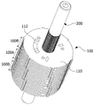
- Figure 2 is a view showing a rotor plate according to the embodiment
- Figure 3 is a view showing an extended surface of the skew reference plane
- Figure 4 is a view showing a rotor consisting of the rotor plate shown in FIG.
- the rotor (100 of FIG. 1) may be formed by stacking a plurality of rotor plates 110.
- the rotor plate 110 may include a rotation shaft hole 111 and the skew check hole 112.
- the rotary shaft hole 111 is formed in the center of the rotor plate 110 is a place where the rotary shaft 200 is pressed.
- Skew confirmation hole 112 is a part for confirming the skew angle with the naked eye even in the state that the outer peripheral surface of the rotor 100 is covered with a can or a molding member.
- Skew confirmation hole 112 includes a skew reference surface (A, B).
- the skew reference planes A and B serve as reference for measuring the skew angle and are formed parallel to the reference line L.
- the reference line L refers to an imaginary line formed in the radial direction with respect to the center CL of the rotation shaft hole 111.
- the skew reference surfaces A and B may be disposed such that the extension surfaces S1 and S2 pass through the center CL of the rotation shaft hole 111.
- the skew reference planes A and B may include a first skew reference plane A and a second skew reference plane B.
- FIG. The first skew reference plane A and the second skew reference plane B may be made of side surfaces of the skew check hole 112 disposed to face each other.
- the size of the skew check hole 112 may be designed such that an angle between the first skew reference plane A and the second skew reference plane B is at least greater than the skew angle. This is to confirm the skew reference planes A and B of the other rotor plate 110 through the skew check hole 112 of the uppermost layer.
- the skew check hole 112 may be disposed between the guide pin holes 114 based on the circumferential direction of the rotor plate 110.
- the guide pin hole 114 is to align and stack the rotor plate 110.
- the rotor 100 may form a plurality of rotors (pucks) by stacking a thin plate-shaped rotor plate 110, in which a guide is inserted into the guide pin hole 114 to align the rotor plate 110. To induce.
- the rotor 100 may include a plurality of rotor cores.
- the rotor 100 may include a first rotor core 100A and a second rotor core 100B.
- the first rotor core 100A and the second rotor core 100B may be implemented in the form of a puck formed by stacking the rotor plates 110 so that the skew check holes 112 are aligned.
- the second rotor core 100B is stacked on the upper and lower portions of the first rotor core 100A around the first rotor core 100A, respectively. It may be made of.
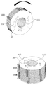
- FIG. 5 is a view illustrating rotors stacked at skew angles
- FIG. 6 is a plan view of a rotor for visually confirming skew angles.
- the first rotor core 100A and the second rotor core 100B may be stacked at a skew angle.
- the skew reference hole (hereinafter referred to as A1) of the first rotor core 100A may be confirmed in the skew check hole 112 of the second rotor core 100B stacked on the top.
- the skew reference plane (hereinafter referred to as A3) of the second rotor core 100B stacked below the first rotor core 100A in the skew confirmation hole 112 of the second rotor core 100B stacked at the top is Can be stacked to be visible.
- the magnet 120 may be attached to the outer circumferential surface of the rotor plate 110.
- FIG. 7 is a diagram illustrating a skew angle visually confirmed through a skew confirmation hole.
- the skew angle R may be checked through the skew check hole 112.
- the first rotor core 100A and the second rotor core 100B are arranged to be skewed at a skew angle R.
- FIG. When the skew reference plane of the second rotor core 100B stacked on the top is A2, the skew check holes 112 of the second rotor core 100B stacked on the top may be visually confirmed.
- An angle between A2 and A1 based on A2 corresponds to the skew angle R of the second rotor core 100B and the first rotor core 100A.
- the angle between A3 and A1 based on A1 corresponds to the skew angle R of the first rotor core 100A and the second rotor core 100B disposed thereunder.
- FIG. 8 is a view illustrating a cover member and a skew hole.
- A1 and A3 may be identified through the skew check hole 112. Therefore, it is possible to check the skew angle with the naked eye even in the state where manufacture of the rotor 100 is completed.
- the distance R1 from the center CL to the edge of the cover member 130 based on the radial direction of the rotor 100 is set so that the skew check hole 112 is not covered by the cover member 130.
- the rotor plate according to one preferred embodiment of the present invention.
- the rotor assembly, the motor, and the vehicle including the same have been described in detail with reference to the accompanying drawings.
- A, B skew reference plane, 100: rotor, 110: rotor plate, 111: rotating shaft hole, 112: skew confirmation hole, 120: magnet, 130; Cover member, 200: rotating shaft, 300: stator
Landscapes
- Engineering & Computer Science (AREA)
- Power Engineering (AREA)
- Chemical & Material Sciences (AREA)
- Combustion & Propulsion (AREA)
- Transportation (AREA)
- Mechanical Engineering (AREA)
- Iron Core Of Rotating Electric Machines (AREA)
- Manufacture Of Motors, Generators (AREA)
- Permanent Field Magnets Of Synchronous Machinery (AREA)
Abstract
본 발명은 회전축홀 및 상기 회전축홀의 중심을 기준하여 반경 방향으로 형성되는 기준선에 평행한 스큐기준면을 포함하는 스큐확인홀을 포함하는 로터 플레이트을 제공한다.
Description
실시예는 로터 플레이트. 로터, 모터 및 이를 포함하는 차량에 관한 것이다.
모터는, 회전 가능하게 형성되는 회전축과, 회전축에 결합되는 로터와, 하우징 내측에 고정되는 스테이터가 마련되는데, 로터의 둘레를 따라 간극을 두고 스테이터가 설치된다. 그리고 스테이터에는 회전 자계를 형성하는 코일이 권선되어 로터와의 전기적 상호 작용을 유발하여 로터의 회전을 유도한다.
일반적으로, 로터는 얇은 판상의 로터 플레이트를 적층하여 복수 개의 로터(퍽, puck)를 형성하고, 각각의 로터를 회전축을 압입하여 제작한다.
이때, 로터는 코깅토크(cogging torque)를 줄이기 위하여 복수 개의 로터들을 일정한 각도로 틀어지게 배치하는 스큐(skew) 타입으로 제작될 수 있다. 그리고 로터는 스큐각도로 틀어져 배치된 로터의 외부를 감싸도록 캔 또는 몰딩부재가 결합되어 제작될 수 있다.
때문에 완성된 로터는 로터의 스큐각도를 육안으로 확인하기 힘든 문제점이 있다. 스큐각도를 확인할 수 있는 로터의 외주면을 캔 또는 몰딩부재가 가리고 있기 때문이다.
이에, 본 발명은 상기한 문제점을 해결하기 위한 것으로, 로터의 외주면을 캔 또는 몰딩부재가 가린 상태에서도 로터의 스큐각도를 육안으로 확인할 수 있는 로터 플레이트. 로터 조립체, 모터 및 이를 포함하는 차량을 제공하는 것을 그 목적으로 한다.
본 발명이 해결하고자 하는 과제는 이상에서 언급된 과제에 국한되지 않으며 여기서 언급되지 않은 또 다른 과제들은 아래의 기재로부터 당업자에게 명확하게 이해될 수 있을 것이다.
상기 목적을 달성하기 위한 실시예는, 회전축홀 및 상기 회전축홀의 중심을 기준하여 반경 방향으로 형성되는 기준선에 평행한 스큐기준면을 포함하는 스큐확인홀을 포함하는 로터 플레이트를 제공할 수 있다.
바람직하게는, 상기 스큐기준면은 마주보는 제1 스큐기준면과 제2 스큐기준면을 포함할 수 있다.
바람직하게는, 상기 제1 스큐기준면과 상기 제2 스큐기준면 사이의 각도는 적어도 스큐 각도보다 크게 형성될 수 있다.
바람직하게는, 복수 개의 가이드핀홀을 포함하고, 원주 방향을 기준으로 상기 스큐확인홀은 상기 가이드핀홀 사이에 배치될 수 있다.
바람직하게는, 상기 스큐기준홀은 상기 스큐기준면의 연장면이 상기 회전축의 홀의 중심을 지날 수 있다.
상기 목적을 달성하기 위한 다른 실시예는, 회전축홀 및 상기 회전축홀의 중심을 기준하여 반경 방향으로 형성되는 기준선에 평행한 스큐기준면을 포함하는 스큐확인홀을 포함하는 복수 개의 로터 플레이트가 적층되는 로터를 제공할 수 있다.
바람직하게는, 로터로서, 상기 회전축홀의 중심을 기준하여 원주 방향으로 상기 스큐기준면이 정렬되도록 적층되는 복수 개의 상기 로터 플레이트를 포함하는 제1 로터코어 및 제2 로터코어를 포함하고, 상기 제1 로터코어의 상기 스큐기준면이 상기 제2 로터코어의 상기 스큐확인홀에 위치하도록 상기 제1 로터코어와 상기 제2 로터코어는 상기 회전축홀의 중심을 기준하여 원주 방향을 따라 상호 틀어져 적층될 수 있다.
바람직하게는, 로터로서, 상기 제1 로터코어의 외주면 및 상기 제2 로터코어의 외주면에 부착되는 마그넷을 포함할 수 있다.
바람직하게는, 로터로서, 상기 스큐확인홀이 노출되도록 상기 제1 로터코어 및 상기 제2 로터코어를 감싸는 커버부재를 포함할 수 있다.
바람직하게는, 로터로서, 상기 스큐기준면은 마주보는 제1 스큐기준면과 제2 스큐기준면을 포함할 수 있다.
바람직하게는, 로터로서, 상기 제1 스큐기준면과 상기 제2 스큐기준면 사이의 각도는 적어도 스큐 각도보다 크게 형성될 수 있다.
바람직하게는, 로터로서, 상기 로터 플레이트는 복수 개의 가이드핀홀을 포함하고, 원주 방향을 기준으로 상기 스큐확인홀은 상기 가이드핀홀 사이에 배치될 수 있다.
바람직하게는. 상기 스큐기준홀은 상기 스큐기준면의 연장면이 상기 회전축의 홀의 중심을 지날 수 있다.
상기 목적을 달성하기 위한 또 다른 실시예는, 회전축과, 상기 회전축이 배치되는 회전축홀을 포함하는 로터 및 상기 로터의 외측에 배치되는 스테이터를 포함하고, 상기 로터는, 상기 회전축홀의 중심을 기준하여 반경 방향으로 형성되는 기준선에 평행한 스큐기준면을 포함하는 스큐확인홀을 포함하는 복수 개의 로터 플레이트가 적층되는 모터를 제공할 수 있다.
상기 목적을 달성하기 위한 또 다른 실시예는, 회전축과, 상기 회전축이 배치되는 회전축홀을 포함하는 로터 및 상기 로터의 외측에 배치되는 스테이터를 포함하는 모터를 포함하고, 상기 로터는, 상기 회전축홀의 중심을 기준하여 반경 방향으로 형성되는 기준선에 평행한 스큐기준면을 포함하는 스큐확인홀을 포함하는 복수 개의 로터 플레이트가 적층되는 차량을 제공할 수 있다.
실시예에 따르면, 캔이나 몰딩부재와 같은 커버부재가 로터의 외주면을 둘러싼 상태에서도 스큐확인홀을 통해 스큐각도를 확인할 수 있는 유리한 효과를 제공한다.
도 1은 실시예에 따른 모터를 도시한 도면,
도 2는 실시예에 따른 로터 플레이트를 도시한 도면,
도 3은 스큐기준면의 연장면을 도시한 도면,
도 4는 도 2에서 도시한 로터 플레이트로 이루어진 로터를 도시한 도면,
도 5는 스큐각도로 틀어져 적층되는 로터들을 도시한 도면,
도 6은 스큐각도를 육안으로 확인할 수 있는 로터의 평면도,
도 7은 스큐확인홀을 통해 육안으로 확인되는 스큐각도를 도시한 도면,
도 8은 커버부재와 스큐홀을 도시한 도면이다.
이하, 본 발명의 바람직한 실시예를 첨부된 도면들을 참조하여 상세히 설명한다. 본 발명의 목적, 특정한 장점들 및 신규한 특징들은 첨부된 도면들과 연관되는 이하의 상세한 설명과 바람직한 실시예들로부터 더욱 명백해질 것이다. 그리고 본 명세서 및 특허청구범위에 사용된 용어나 단어는 통상적이거나 사전적인 의미로 한정하여 해석되어서는 아니 되며, 발명자는 그 자신의 발명을 가장 최선의 방법으로 설명하기 위해서 용어의 개념을 적절하게 정의할 수 있다는 원칙에 입각하여, 본 발명의 기술적 사상에 부합되는 의미와 개념으로 해석되어야만 한다. 그리고 본 발명을 설명함에 있어서, 본 발명의 요지를 불필요하게 흐릴 수 있는 관련된 공지기술에 대한 상세한 설명은 생략한다.
도 1은 실시예에 따른 모터를 도시한 도면이다.
도 1을 참조하면, 실시예에 따른 모터(10)는, 로터(100)와, 회전축(200)와, 스테이터(300)를 포함할 수 있다.
로터(100)는 스테이터(300)의 내측에 배치된다. 로터(100)는 로터코어에 마그네트가 결합되어 구성될 수도 있고, 경우에 따라, 로터코어와 마그네트가 일체로 구성될 수도 있다. 또한 로터(100)는 마그네트가 로터코어의 외주면에 결합되는 타입으로 구성될 수 있거나, 마그네트가 로터코어의 포켓에 삽입되는 타입으로 구성될 수 있다. 로터(100)의 상측에는 로터(100)의 위치 정보 획득을 위한 센싱 마그네트가 플레이트에 결합되어 설치되거나, 이와 유사한 로터 위치 감지수단이 설치될 수 있다.
회전축(200)은 로터(100)에 결합될 수 있다.
스테이터(200)는 환형의 요크 부분과, 둘레 방향을 따라 배치되고 요크로부터 직경 방향 내측을 향해 등각도 간격으로 돌출되는 티스의 부분을 포함하는 복수의 강판을 적층하여 구성될 수 있다. 회전 자계를 형성하는 코일이 티스에 감길 수 있다.
스테이터(200)에 감긴 코일에 전류가 공급되면, 로터(100)와의 전기적 상호 작용을 유발하여 로터(100)의 회전을 유도한다. 로터(100)가 회전하면 회전축(200)이 회전하면서 동력을 제공한다.
이러한 모터는 차량의 조향시스템 등에 적용되어 조향력을 보조하는 모터(예를 들어, EPS: Electronic Power Steering)일 수 있다.
도 2는 실시예에 따른 로터 플레이트를 도시한 도면이고, 도 3은 스큐기준면의 연장면을 도시한 도면이고, 도 4는 도 2에서 도시한 로터 플레이트로 이루어진 로터를 도시한 도면이고
도 2 내지 도 4를 참조하면, 로터(도 1의 100)는 복수 개의 로터 플레이트(110)가 적층되어 이루어 질 수 있다.
로터 플레이트(110)는 회전축홀(111)과 스큐확인홀(112)을 포함할 수 있다. 회전축홀(111)은 로터 플레이트(110)의 중심부에 형성되어 회전축(200)이 압입되는 곳이다. 스큐확인홀(112)은 로터(100)의 외주면이 캔이나 몰딩부재로 가려진 상태에서도 육안으로 스큐각도를 확인시켜 주는 부분이다.
스큐확인홀(112)은 스큐기준면(A,B)을 포함한다. 스큐기준면(A,B)은 스큐각도를 측정하는 기준이 되는 곳으로 기준선(L)에 평행하게 형성된다. 여기서 기준선(L)이라 함은 회전축홀(111)의 중심(CL)을 기준으로 반경 방향으로 형성되는 가상의 선을 의미한다.
스큐기준면(A,B)은 그 연장면(S1,S2)이 회전축홀(111)의 중심(CL)을 지나도록 배치될 수 있다.
스큐확인홀(112)의 스큐기준면(A,B)이 형성되도록 로터 플레이트(110)의 일부 영역이 절개된 형태로 형성될 수 있다. 한편, 스큐기준면(A,B)은 제1 스큐기준면(A)과 제2 스큐기준면(B)을 포함할 수 있다. 제1 스큐기준면(A)과 제2 스큐기준면(B)은 마주 보도록 배치되는 스큐확인홀(112)의 측면으로 이루어질 수 있다.
한편, 스큐확인홀(112)의 크기는 제1 스큐기준면(A)과 제2 스큐기준면(B) 사이의 각도가 적어도 스큐 각도보다 크게 형성되도록 설계될 수 있다. 이는 최상층의 스큐확인홀(112)을 통해 다른 로터 플레이트(110)의 스큐기준면(A,B)을 확인하기 위함이다.
스큐확인홀(112)은 로터 플레이트(110)의 원주 방향을 기준으로 가이드핀홀(114) 사이에 배치될 수 있다. 가이드핀홀(114)은 로터 플레이트(110)를 정렬하여 적층하기 위한 것이다. 로터(100)는 얇은 판상의 로터 플레이트(110)를 적층하여 복수 개의 로터(퍽, puck)를 형성할 수 있는데, 이때, 가이드핀홀(114)에 가이드가 삽입되어 로터 플레이트(110)의 정렬을 유도하게 된다.
도 4를 참조하면, 로터(100)는 복수 개의 로터코어들로 이루어질 수 있다. 예를 들어, 로터(100)는 제1 로터코어(100A)와 제2 로터코어(100B)를 포함할 수 있다. 제1 로터코어(100A)와 제2 로터코어(100B)는 스큐확인홀(112)이 각각 정렬되도록 로터 플레이트(110)가 적층되어 이루어진 퍽(puck) 형태로 실시될 수 있다.
도 4에서 도시한 바와 같이, 로터(100)는 제1 로터코어(100A)를 중심으로 제1 로터코어(100A)의 상부 및 하부에 각각 제2 로터코어(100B)가 적층되어 모두 3개의 로터로 이루어질 수 있다.
도 5는 스큐각도로 틀어져 적층되는 로터들을 도시한 도면이고, 도 6은 스큐각도를 육안으로 확인할 수 있는 로터의 평면도이다.
도 5 및 도 6을 참조하면, 제1 로터코어(100A)와 제2 로터코어(100B)는 스큐각도로 틀어져 적층 될 수 있다. 이때, 최상위에 적층된 제2 로터코어(100B)의 스큐확인홀(112)에서 제1 로터코어(100A)의 스큐기준면(이하, A1이라 한다)이 확인되도록 적층 될 수 있다. 그리고 최상위에 적층된 제2 로터코어(100B)의 스큐확인홀(112)에서 제1 로터코어(100A)의 하부에 적층된 제2 로터코어(100B)의 스큐기준면(이하. A3라 한다)이 보이도록 적층 될 수 있다.
로터 플레이트(110)의 외주면에는 마그넷(120)이 부착될 수 있다.
도 7은 스큐확인홀을 통해 육안으로 확인되는 스큐각도를 도시한 도면이다.
도 6 및 도 7을 참조하면, 스큐확인홀(112)을 통해 스큐각도(R)를 확인할 수 있다. 제1 로터코어(100A)와 제2 로터코어(100B)는 스큐각도(R)로 틀어져 배치된다. 최상위에 적층된 제2 로터코어(100B)의 스큐기준면을 A2라 할 때, 최상위 측에 적층된 제2 로터코어(100B)의 스큐확인홀(112)에서 A1과 A3를 육안으로 확인할 수 있다.
A2를 기준으로 A2와 A1의 사이각이 제2 로터코어(100B)와 제1 로터코어(100A)의 스큐각도(R)에 해당한다. 그리고 A1을 기준으로 A3와 A1의 사이각이 제1 로터코어(100A)와 그 아래에 배치되는 제2 로터코어(100B)의 스큐각도(R)에 해당한다.
도 8은 커버부재와 스큐홀을 도시한 도면이다.
도 8을 참조하면, 캔 또는 몰딩부재와 같은 커버부재(130)가 로터 플레이트(110)의 외주면을 감싸더라도 스큐확인홀(112)을 통해 A1과 A3를 확인할 수 있다. 때문에 로터(100)의 제조가 완료된 상태에서도 육안으로 스큐각도를 확인하는 것이 가능한다.
로터(100)의 반경 방향을 기준으로 중심(CL)에서 커버부재(130)의 에지까지의 거리(R1)는 커버부재(130)에 의해 스큐확인홀(112)이 가려지지 않도록 설정된다.
이상으로 본 발명의 바람직한 하나의 실시예에 따른 로터 플레이트. 로터 조립체, 모터 및 이를 포함하는 차량에 관하여 첨부된 도면을 참조하여 구체적으로 살펴보았다.
이상의 설명은 본 발명의 기술 사상을 예시적으로 설명한 것에 불과한 것으로서, 본 발명이 속하는 기술 분야에서 통상의 지식을 가진 자라면 본 발명의 본질적인 특성에서 벗어나지 않는 범위 내에서 다양한 수정, 변경 및 치환이 가능할 것이다. 따라서, 본 발명에 개시된 실시예 및 첨부된 도면들은 본 발명의 기술 사상을 한정하기 위한 것이 아니라 설명하기 위한 것이고, 이러한 실시예 및 첨부된 도면에 의하여 본 발명의 기술 사상의 범위가 한정되는 것은 아니다. 본 발명의 보호 범위는 아래의 청구범위에 의하여 해석되어야 하며, 그와 동등한 범위 내에 있는 모든 기술 사상은 본 발명의 권리범위에 포함되는 것으로 해석되어야 할 것이다.
<부호의 설명>
A,B: 스큐기준면, 100: 로터, 110: 로터 플레이트, 111: 회전축홀, 112: 스큐확인홀, 120: 마그넷, 130; 커버부재, 200: 회전축, 300: 스테이터
Claims (15)
- 회전축홀 및 상기 회전축홀의 중심을 기준하여 반경 방향으로 형성되는 기준선에 평행한 스큐기준면을 포함하는 스큐확인홀을 포함하는 로터 플레이트.
- 제1 항에 있어서,상기 스큐기준면은 마주보는 제1 스큐기준면과 제2 스큐기준면을 포함하는 로터 플레이트.
- 제1 항에 있어서,상기 제1 스큐기준면과 상기 제2 스큐기준면 사이의 각도는 적어도 스큐 각도보다 크게 형성되는 로터 플레이트.
- 제1 항에 있어서,복수 개의 가이드핀홀을 포함하고,원주 방향을 기준으로 상기 스큐확인홀은 상기 가이드핀홀 사이에 배치되는 로터 플레이트.
- 제1 항에 있어서,상기 스큐기준홀은 상기 스큐기준면의 연장면이 상기 회전축의 홀의 중심을 지나는 로터플레이트.
- 회전축홀 및 상기 회전축홀의 중심을 기준하여 반경 방향으로 형성되는 기준선에 평행한 스큐기준면을 포함하는 스큐확인홀을 포함하는 복수 개의 로터 플레이트가 적층되는 로터.
- 제6 항에 있어서,상기 회전축홀의 중심을 기준하여 원주 방향으로 상기 스큐기준면이 정렬되도록 적층되는 복수 개의 상기 로터 플레이트를 포함하는 제1 로터코어 및 제2 로터코어를 포함하고,상기 제1 로터코어의 상기 스큐기준면이 상기 제2 로터코어의 상기 스큐확인홀에 위치하도록 상기 제1 로터코어와 상기 제2 로터코어는 상기 회전축홀의 중심을 기준하여 원주 방향을 따라 상호 틀어져 적층되는 로터.
- 제7 항에 있어서,상기 제1 로터코어의 외주면 및 상기 제2 로터코어의 외주면에 부착되는 마그넷을 포함하는 로터.
- 제8 항에 있어서,상기 스큐확인홀이 노출되도록 상기 제1 로터코어 및 상기 제2 로터코어를 감싸는 커버부재를 포함하는 로터.
- 제7 항에 있어서,상기 스큐기준면은 마주보는 제1 스큐기준면과 제2 스큐기준면을 포함하는 로터.
- 제10 항에 있어서,상기 제1 스큐기준면과 상기 제2 스큐기준면 사이의 각도는 적어도 스큐 각도보다 크게 형성되는 로터.
- 제6 항에 있어서,상기 로터 플레이트는 복수 개의 가이드핀홀을 포함하고,원주 방향을 기준으로 상기 스큐확인홀은 상기 가이드핀홀 사이에 배치되는 로터.
- 제6 항에 있어서,상기 스큐기준홀은 상기 스큐기준면의 연장면이 상기 회전축의 홀의 중심을 지나는 로터.
- 회전축;상기 회전축이 배치되는 회전축홀을 포함하는 로터;및상기 로터의 외측에 배치되는 스테이터를 포함하고,상기 로터는,상기 회전축홀의 중심을 기준하여 반경 방향으로 형성되는 기준선에 평행한 스큐기준면을 포함하는 스큐확인홀을 포함하는 복수 개의 로터 플레이트가 적층되는 모터.
- 회전축과, 상기 회전축이 배치되는 회전축홀을 포함하는 로터 및 상기 로터의 외측에 배치되는 스테이터를 포함하는 모터를 포함하고,상기 로터는, 상기 회전축홀의 중심을 기준하여 반경 방향으로 형성되는 기준선에 평행한 스큐기준면을 포함하는 스큐확인홀을 포함하는 복수 개의 로터 플레이트가 적층되는 차량.
Priority Applications (4)
| Application Number | Priority Date | Filing Date | Title |
|---|---|---|---|
| US16/070,214 US11183894B2 (en) | 2016-01-14 | 2016-12-07 | Rotor plate, rotor, motor and vehicle including same |
| CN201680079060.4A CN108496292B (zh) | 2016-01-14 | 2016-12-07 | 转子板、转子、马达和包括该马达的车辆 |
| CN202110176209.3A CN112821609B (zh) | 2016-01-14 | 2016-12-07 | 转子板、转子、马达和包括该马达的车辆 |
| US17/510,034 US11621595B2 (en) | 2016-01-14 | 2021-10-25 | Rotor plate, rotor, motor and vehicle including same |
Applications Claiming Priority (2)
| Application Number | Priority Date | Filing Date | Title |
|---|---|---|---|
| KR10-2016-0004770 | 2016-01-14 | ||
| KR1020160004770A KR20170085308A (ko) | 2016-01-14 | 2016-01-14 | 로터 플레이트. 로터코어 조립체, 모터 및 이를 포함하는 차량 |
Related Child Applications (2)
| Application Number | Title | Priority Date | Filing Date |
|---|---|---|---|
| US16/070,214 A-371-Of-International US11183894B2 (en) | 2016-01-14 | 2016-12-07 | Rotor plate, rotor, motor and vehicle including same |
| US17/510,034 Continuation US11621595B2 (en) | 2016-01-14 | 2021-10-25 | Rotor plate, rotor, motor and vehicle including same |
Publications (1)
| Publication Number | Publication Date |
|---|---|
| WO2017122930A1 true WO2017122930A1 (ko) | 2017-07-20 |
Family
ID=59311850
Family Applications (1)
| Application Number | Title | Priority Date | Filing Date |
|---|---|---|---|
| PCT/KR2016/014259 Ceased WO2017122930A1 (ko) | 2016-01-14 | 2016-12-07 | 로터 플레이트, 로터, 모터 및 이를 포함하는 차량 |
Country Status (4)
| Country | Link |
|---|---|
| US (2) | US11183894B2 (ko) |
| KR (1) | KR20170085308A (ko) |
| CN (2) | CN112821609B (ko) |
| WO (1) | WO2017122930A1 (ko) |
Cited By (1)
| Publication number | Priority date | Publication date | Assignee | Title |
|---|---|---|---|---|
| CN114270662A (zh) * | 2019-08-19 | 2022-04-01 | Lg伊诺特有限公司 | 电机 |
Families Citing this family (3)
| Publication number | Priority date | Publication date | Assignee | Title |
|---|---|---|---|---|
| KR101668660B1 (ko) * | 2015-01-15 | 2016-10-24 | 하남전기주식회사 | 모터의 로터 |
| KR102683454B1 (ko) * | 2018-09-18 | 2024-07-10 | 엘지이노텍 주식회사 | 모터 |
| CN113765312B (zh) * | 2021-09-28 | 2022-08-02 | 安徽威灵汽车部件有限公司 | 转子压装方法、转子、电动助力转向电机及车辆 |
Citations (5)
| Publication number | Priority date | Publication date | Assignee | Title |
|---|---|---|---|---|
| JPH0360855U (ko) * | 1989-10-13 | 1991-06-14 | ||
| JP2005218194A (ja) * | 2004-01-28 | 2005-08-11 | Nsk Ltd | モータ及びそれを用いた電動パワーステアリング装置 |
| KR20050122557A (ko) * | 2004-06-24 | 2005-12-29 | 엘지전자 주식회사 | 세탁기의 모터 |
| JP2013110930A (ja) * | 2011-11-24 | 2013-06-06 | Nissan Motor Co Ltd | ロータとその製造方法 |
| JP2015061466A (ja) * | 2013-09-20 | 2015-03-30 | 本田技研工業株式会社 | 回転電機のロータ |
Family Cites Families (14)
| Publication number | Priority date | Publication date | Assignee | Title |
|---|---|---|---|---|
| JP3493865B2 (ja) | 1995-12-27 | 2004-02-03 | アイシン・エィ・ダブリュ株式会社 | モータ |
| JP3487180B2 (ja) * | 1998-06-15 | 2004-01-13 | 株式会社日立製作所 | 永久磁石形同期回転電機のロータ |
| JP2001028852A (ja) * | 2000-01-01 | 2001-01-30 | Hitachi Ltd | 永久磁石回転型回転電機及びその製造方法 |
| JP2002136015A (ja) * | 2000-10-24 | 2002-05-10 | Mitsubishi Heavy Ind Ltd | 電動機 |
| US20070152521A1 (en) | 2004-06-24 | 2007-07-05 | Lg Electronics, Inc | Motor of washing machine |
| KR101054417B1 (ko) * | 2004-06-24 | 2011-08-04 | 엘지전자 주식회사 | 세탁기의 모터 |
| DE102005060116A1 (de) * | 2004-12-20 | 2006-07-06 | Danfoss Compressors Gmbh | Rotor für einen elektrischen Motor |
| CN103299516A (zh) * | 2011-01-11 | 2013-09-11 | 株式会社捷太格特 | 马达驱动力传动装置 |
| EP2557661B1 (en) * | 2011-08-10 | 2020-03-11 | LG Innotek Co., Ltd. | Rotor core of motor |
| US10008892B2 (en) * | 2012-05-31 | 2018-06-26 | Edwards Japan Limited | IPM motor for vacuum pump |
| CN203039449U (zh) | 2012-11-14 | 2013-07-03 | 黄迪 | 电动三轮车专用电机具有改善霍尔输出波形的电机转子 |
| JP5873420B2 (ja) * | 2012-11-30 | 2016-03-01 | 三菱電機株式会社 | ロータコアの製造方法 |
| KR102120314B1 (ko) * | 2013-11-04 | 2020-06-08 | 엘지이노텍 주식회사 | 로터 및 이를 포함하는 모터 |
| CN103779993A (zh) | 2014-02-10 | 2014-05-07 | 王必生 | 永磁电机斜极转子铁芯结构及叠装方法 |
-
2016
- 2016-01-14 KR KR1020160004770A patent/KR20170085308A/ko not_active Ceased
- 2016-12-07 US US16/070,214 patent/US11183894B2/en active Active
- 2016-12-07 CN CN202110176209.3A patent/CN112821609B/zh active Active
- 2016-12-07 CN CN201680079060.4A patent/CN108496292B/zh active Active
- 2016-12-07 WO PCT/KR2016/014259 patent/WO2017122930A1/ko not_active Ceased
-
2021
- 2021-10-25 US US17/510,034 patent/US11621595B2/en active Active
Patent Citations (5)
| Publication number | Priority date | Publication date | Assignee | Title |
|---|---|---|---|---|
| JPH0360855U (ko) * | 1989-10-13 | 1991-06-14 | ||
| JP2005218194A (ja) * | 2004-01-28 | 2005-08-11 | Nsk Ltd | モータ及びそれを用いた電動パワーステアリング装置 |
| KR20050122557A (ko) * | 2004-06-24 | 2005-12-29 | 엘지전자 주식회사 | 세탁기의 모터 |
| JP2013110930A (ja) * | 2011-11-24 | 2013-06-06 | Nissan Motor Co Ltd | ロータとその製造方法 |
| JP2015061466A (ja) * | 2013-09-20 | 2015-03-30 | 本田技研工業株式会社 | 回転電機のロータ |
Cited By (2)
| Publication number | Priority date | Publication date | Assignee | Title |
|---|---|---|---|---|
| CN114270662A (zh) * | 2019-08-19 | 2022-04-01 | Lg伊诺特有限公司 | 电机 |
| CN114270662B (zh) * | 2019-08-19 | 2023-06-30 | Lg伊诺特有限公司 | 电机 |
Also Published As
| Publication number | Publication date |
|---|---|
| US11621595B2 (en) | 2023-04-04 |
| KR20170085308A (ko) | 2017-07-24 |
| CN112821609B (zh) | 2024-01-30 |
| US20190068013A1 (en) | 2019-02-28 |
| US20220045565A1 (en) | 2022-02-10 |
| US11183894B2 (en) | 2021-11-23 |
| CN108496292A (zh) | 2018-09-04 |
| CN108496292B (zh) | 2021-03-05 |
| CN112821609A (zh) | 2021-05-18 |
Similar Documents
| Publication | Publication Date | Title |
|---|---|---|
| WO2017122930A1 (ko) | 로터 플레이트, 로터, 모터 및 이를 포함하는 차량 | |
| WO2019135549A1 (ko) | 모터 | |
| WO2016182117A1 (en) | Stack structure of rotor core | |
| WO2017150909A1 (ko) | 버스바 조립체, 이를 포함하는 모터 | |
| WO2016003014A1 (ko) | 복합 자속을 이용한 모터 | |
| WO2016076599A1 (ko) | 모터 | |
| WO2013133474A1 (ko) | 매립형 영구자석 전동기 | |
| WO2018139791A1 (ko) | 모터 | |
| WO2017217729A1 (ko) | 로터 및 이를 포함하는 모터 | |
| WO2018044038A1 (ko) | 라인기동식 동기형 릴럭턴스 전동기 및 그 회전자 | |
| WO2015115834A1 (ko) | 센서 모듈, 및 이를 포함하는 모터 | |
| WO2020060093A1 (ko) | 모터 | |
| WO2019156440A1 (ko) | 모터 | |
| WO2019050199A1 (ko) | 모터 | |
| WO2021060817A1 (ko) | 모터 | |
| WO2018131905A1 (ko) | 모터 | |
| WO2017061694A1 (ko) | 영구자석형 로터 및 이의 제조방법 | |
| WO2020045936A1 (ko) | 모터 | |
| CN1819405B (zh) | 具有将磁体固定在转子中的盖板的转子 | |
| WO2020197138A1 (ko) | 모터 | |
| WO2019017699A1 (ko) | 모터 | |
| WO2017069488A1 (ko) | 로터 코어, 로터 및 이를 포함하는 모터 | |
| KR102621316B1 (ko) | 로터 플레이트. 로터코어 조립체, 모터 및 이를 포함하는 차량 | |
| WO2022220586A1 (ko) | 모터 | |
| WO2018056561A1 (ko) | 무정지 모터 |
Legal Events
| Date | Code | Title | Description |
|---|---|---|---|
| 121 | Ep: the epo has been informed by wipo that ep was designated in this application |
Ref document number: 16885241 Country of ref document: EP Kind code of ref document: A1 |
|
| NENP | Non-entry into the national phase |
Ref country code: DE |
|
| 122 | Ep: pct application non-entry in european phase |
Ref document number: 16885241 Country of ref document: EP Kind code of ref document: A1 |