WO2017125997A1 - Tige d'actionnement - Google Patents
Tige d'actionnement Download PDFInfo
- Publication number
- WO2017125997A1 WO2017125997A1 PCT/JP2016/051235 JP2016051235W WO2017125997A1 WO 2017125997 A1 WO2017125997 A1 WO 2017125997A1 JP 2016051235 W JP2016051235 W JP 2016051235W WO 2017125997 A1 WO2017125997 A1 WO 2017125997A1
- Authority
- WO
- WIPO (PCT)
- Prior art keywords
- fuse cylinder
- holding member
- end side
- fuse
- cylindrical
- Prior art date
- Legal status (The legal status is an assumption and is not a legal conclusion. Google has not performed a legal analysis and makes no representation as to the accuracy of the status listed.)
- Ceased
Links
Images









Classifications
-
- H—ELECTRICITY
- H01—ELECTRIC ELEMENTS
- H01H—ELECTRIC SWITCHES; RELAYS; SELECTORS; EMERGENCY PROTECTIVE DEVICES
- H01H31/00—Air-break switches for high tension without arc-extinguishing or arc-preventing means
- H01H31/02—Details
-
- H—ELECTRICITY
- H01—ELECTRIC ELEMENTS
- H01H—ELECTRIC SWITCHES; RELAYS; SELECTORS; EMERGENCY PROTECTIVE DEVICES
- H01H85/00—Protective devices in which the current flows through a part of fusible material and this current is interrupted by displacement of the fusible material when this current becomes excessive
- H01H85/02—Details
Definitions
- the present invention relates to an operating rod, and more particularly to an operating rod used when replacing a fuse cylinder housed in a cylindrical cutout.
- the tip of the operating rod is fitted into the fuse cylinder from below the fuse cylinder housed in the cylindrical cutout, and then the operating rod is rotated in a predetermined direction around its axis.
- the engaging portion of the operating rod is engaged with the protrusion of the fuse cylinder, and then the operating rod is lowered downward to release the engaged state between the fuse cylinder and the cylindrical cutout.
- the tube can be removed.
- the cylindrical cutout is installed at the top of the utility pole and is located above the ground. For this reason, when a work vehicle for high places is not used, an extension rod is connected to the operation rod and the operation rod is elongated, and a fuse cylinder is installed in the cylindrical cutout from the ground. . In this mounting operation, the conventional operation rod has a problem that it is difficult to determine whether or not the fuse cylinder is mounted in the cutout from the ground.
- the present invention has an object to provide an operation rod that can easily determine whether or not a fuse cylinder is attached in a cutout in a cylindrical cutout at a high place from the ground. is there.
- the present invention is an operation rod used when replacing a fuse cylinder stored in a cylindrical cutout,
- a casing having at least a housing portion that opens at one end side into which the fuse cylinder is inserted, and a holding member that is slidable in the casing axial direction in the housing portion and that can detachably hold the fuse cylinder;
- the holding member When attaching the fuse cylinder to the cylindrical cutout using the operation rod, the holding member is positioned on the one end side in a state where the holding member holds the fuse cylinder, and the holding member is the fuse In a state where the tube is not held, the holding member is located on the other end side,
- a confirmation means for confirming the position of the holding member is provided.
- a moving member is provided on the outer periphery of the casing so as to be movable in the axial direction, and the moving member and the holding member are integrally movable in the axial direction, It may be possible to confirm that the holding member does not hold the fuse cylinder by positioning the moving member on the other end side.
- the holding member may have a plurality of arm portions that are positioned closer to the axial center as the inner surface reaches the other end side in the axial direction of the casing.
- the present invention is provided with a holding member that is slidable in the axial direction in the casing and capable of detachably holding the fuse cylinder, and when attaching the fuse cylinder to the cylindrical cutout using the operation rod, When the holding member holds the fuse cylinder, the holding member is positioned on one end side. When the holding member does not hold the fuse cylinder, the holding member is positioned on the other end side.
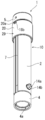
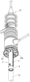
- FIG. 3 is a perspective view of the operating rod according to the first embodiment of the present invention as viewed from above with a moving member positioned upward.
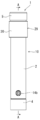
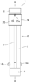
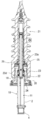
- the top view of FIG. FIG. 4 is a sectional view taken along line AA in FIG. 3.
- FIG. 2 is a perspective view of a state where a moving member is positioned below from the state of FIG. 1.
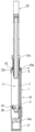
- the left view of FIG. FIG. 9 is a sectional view taken along line BB in FIG.
- the front view of FIG. The perspective view seen from the connection member which concerns on Example 1 of this invention.
- FIG. 17 is a bottom view of FIG. 16.
- FIG. 17 is a sectional view taken along the line CC of FIG.
- FIG. 19 is a cross-sectional view corresponding to FIG. 18 in a state where a fuse cylinder is attached to the cylindrical cutout of FIG. 16.
- the perspective view seen from the bottom of the fuse cylinder which concerns on Example 1 of this invention.
- the perspective view seen from the top of FIG. The front view of FIG. It is the perspective view seen from the state which inserted the operation stick
- FIG. 16 shows an extension stick
- the longitudinal cross-sectional view of FIG. The perspective view seen from the state which made the operation stick
- the perspective view seen from the bottom of FIG. The side view seen from the state which made the operation cylinder shown in FIG. 7 hold
- FIG. 28 is a sectional view taken along line DD of FIG. Sectional drawing of an example of the operating rod which concerns on Example 2 of this invention.
- FIG. 30 is a cross-sectional view illustrating a state in which the holding member extends in the axial direction from the state of FIG. 29.
- FIG. 34 is a cross-sectional view of a holding member used for the operation rod shown in FIG. 33.
- FIG. 34 is a perspective view of an urging member used for the operation rod shown in FIG. 33.
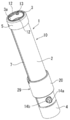
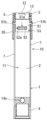
- FIG. 1 is a perspective view as viewed from above the operation rod 1 of the present invention
- FIG. 2 is a perspective view as viewed from the opposite side of FIG. 1
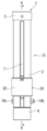
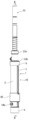
- FIG. 3 is a front view of FIG. 1
- FIG. 1 is a right side view of FIG. 1
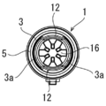
- FIG. 5 is a top view of FIG.
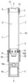
- the operation rod 1 is a hollow cylindrical member 2 having both ends open, and a cylindrical member 2 on the side where the fuse cylinder is inserted in the axial direction XX of the cylindrical member 2.
- a cylindrical lid member 3 that is screwed into a female screw engraved at one end (tip) that is an end and that is open at both ends, and the other end of the cylindrical member 2 in the axis XX direction It has the connection member 4 provided in the part (rear part).
- the outer periphery of the lid member 3 is covered with an insulating member 5.
- a casing 10 is constituted by the cylindrical member 2, the lid member 3, and the connecting member 4.
- a storage portion 11 having one end opened is formed.
- the cross section of the casing 10 is formed in a circular shape in this embodiment, it can be formed in an arbitrary shape such as a polygonal shape such as a square or an irregular shape other than the circular shape.
- the cylindrical member 2 has a pair of slits 7 and 7 penetrating the front and back thereof at positions facing each other and in a cylindrical shape.
- the member 2 is formed in the axis XX direction.
- the other ends of the slits 7 open to the other end of the cylindrical member 2, but one end side does not reach the one end of the cylindrical member 2. Is formed.
- an arcuate engagement portion centering on the axial center of the tubular member 2 is formed on the inner peripheral surface of one end portion (tip portion) of the lid member 3.
- a pair of 12 are formed to protrude inward in a position facing each other.
- both engaging portions 12 are partially provided in the circumferential direction of the lid member 3, and a non-engaging portion 3 a formed of a peripheral wall is provided between them.
- the connecting member 4 is detachably attached to the cylindrical member 2 by bolts 14a and nuts 14b on the other end side of the cylindrical member 2.
- the connecting member 4 has a female screw hole 4a opened at least on the other end side, and a male screw (not shown) formed at the tip of the extension rod 15 is screwed into the female screw hole 4a. As shown by the chain line in FIG. 23, the extension rod 15 can be removably attached to the connecting member 4.
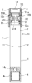
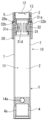
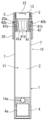
- a holding member 16 is provided in the accommodating portion 11 of the cylindrical member 2 so as to be slidable in the axial center XX direction of the cylindrical member 2.
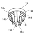
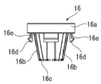
- the holding member 16 has a cylindrical base portion 16a, and protrudes from one end portion of the base portion 16a toward the other end side. It has a plurality of arm portions 16b located on the ⁇ X side. Although the number of the arm portions 16b can be arbitrarily set, in the present embodiment, six arm portions 16b are provided at equal intervals in the circumferential direction.
- a retaining portion 16c is formed at the other end of the arm portion 16b.
- each claw portion 16d configured by snap fit are provided at equal intervals in the circumferential direction so as to protrude toward the other end side, and the base portion 16a of the claw portion 16d is provided.
- An engaging groove 16e is formed on the side portion.
- the base portion 16a, the arm portion 16b, the retaining portion 16c, and the claw portion 16d are integrally formed of a resin having elastic force.
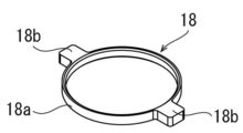
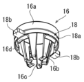
- a connecting member 18 is provided on the outer periphery of the holding member 16. As shown in FIG. 13, the connecting member 18 is formed integrally with a ring-shaped ring portion 18 a and two projecting portions 18 b that protrude from the ring portion 18 a to the outside in the radial direction centering on the axis. 6, 9, and 14, the inner peripheral surface of the ring portion 18 a is fitted into the engagement groove 16 e of the claw portion 16 d of the holding member 16, so that the holding member 16 and the ring portion 18 a are It is integrated and located in the storage part 11. Further, the protrusion 18 b is provided at a position substantially opposed in the circumferential direction, and the protrusion 18 b passes through the slit 7 and protrudes outward from the outer peripheral surface of the tubular member 2.
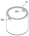
- An annular moving member 20 is provided on the outer peripheral portion of the cylindrical member 2 so as to be freely movable in the axial direction XX. As shown in FIG. 15, the moving member 20 is formed with two mounting holes 20 a that open at least inward at positions facing each other in the circumferential direction. The protrusion 18b of the connecting member 18 is fitted in the mounting hole 20a.
- the holding member 16, the connecting member 18, and the moving member 20 can be moved integrally in the axis XX direction of the cylindrical member 2. Further, the moving member 20 constitutes confirmation means 29 that can confirm the position of the fuse cylinder 23 from the outside of the casing 10.
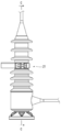
- the cylindrical cutout 21 which is a target using the operation rod 1 will be described.
- the cylindrical cutout 21 is normally installed perpendicular to a utility pole or the like, and will be described with the upper side of FIG.
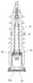
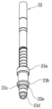
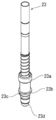
- the cylindrical cutout 21 shown in FIGS. 16 to 18 has a storage space 22 for storing the fuse cylinder 23 shown in FIGS. 20 to 22, and the storage space 22 is open at the bottom. As shown in FIG. 17, the opening is closed so as to be openable by a lid member 24 composed of a flexible piece member 24 a made up of a plurality of divided pieces provided at the lower end. Further, a fuse cylinder 23 as shown in FIGS. 20 to 22 can be inserted into and removed from the storage space 22, and a fuse cylinder holding a snap fit for holding the fuse cylinder 23 at a predetermined mounting position thereof. A member 25 is provided. As shown in FIG. 19, the fuse cylinder holding member 25 is pressure-engaged with a cylindrical protrusion 23 a provided on the mounting side (other end side) of the operation rod 1 in the accommodated fuse cylinder 23. It is like that.
- a flange 23b is formed, and the outer shape of the flange 23b is set larger than the inner diameter of the opening on one end side of the lid member 3, and as shown in FIG. 28, the flange 23b Is in contact with the lid member 3, and the other end side of the collar part 23b can be inserted into the storage part 11, but the one end side of the collar part 23b cannot be inserted.
- the diameter is larger than the inner diameter of the engaging portion 12 provided on the lid member 3 and smaller than the non-engaging portion 3a, and further has a circumferential length.
- An engaged portion 23c having a length shorter than that of the non-engaging portion 3a is formed to project, and the engaged portion 23c can be engaged with the other end side surface of the engaging portion 12 provided on the lid member 3. ing.
- each piece member 24 a in the lid member 24 is formed in a shape in which a circle is radially divided at equal intervals in the circumferential direction, and is adjacent to the circumferential direction around the axis of the cylindrical member 2.
- the lid member 24 is arranged so that the sides to be in contact with each other, and the lid member 24 closes the lower opening 22 a of the storage space 22. Further, since the piece member 24a is flexible, the operation rod 1 can be inserted into the storage space 22 from below at the center of the lid member 24 as shown in FIGS. It has become.
- one end side portion of the operating rod 1 is connected to the cylinder as shown in FIGS.
- the piece member 24 a located at the center of the lid member 24 is inserted into the storage space 22 while being pushed upward.
- the operating rod 1 is pushed upward, and the lower portion of the fuse cylinder 23 is inserted into the storage portion 11 from the front portion of the operating rod 1, and the non-engaging portion 3 a of the operating rod 1 is engaged with the engagement of the fuse cylinder 23.
- the operation rod 1 is inserted until the flange portion 23b of the fuse cylinder 23 comes into contact with the tip of the operation rod 1 at the joint portion 23c.
- the operating rod 1 is rotated in the other direction (in the present embodiment, the left direction) as viewed from one end around the axis, and as shown in FIG.
- the joint portion 12 is engaged between the flange portion 23b of the fuse cylinder 23 and the engaged portion 23c.
- the fuse cylinder 23 is also moved downward together with the operating rod 1, and the projection 23 a of the fuse cylinder 23 and the fuse cylinder holding member of the cylindrical cutout 21 are moved.
- the fuse cylinder 23 can be removed from the cylindrical cutout 21 by releasing the engagement with the cylinder 25.
- the extension rod 15 is attached to the female screw hole 4a of the connecting member 4 of the operation rod 1.
- the fuse cylinder 22 can be mounted in the cylindrical cutout 21 installed at a high place from the ground.
- the fuse cylinder 22 may be attached to the cylindrical cutout 21 by using a work vehicle for high places without attaching the extension rod 15 to the connection member 4 of the operation rod 1.
- the moving member 20 is moved to one end side of the casing 10 so that the holding member 16 is positioned on one end side, the lower side of the fuse cylinder 23 is moved to the operation rod 1.
- the holding member 16 holds the held portion 23 d at the lower end of the fuse cylinder 23 from one end side of the fuse cylinder 23.
- the fuse cylinder 23 is rotated in one direction with respect to the operating rod 1 about its axis, and the engaging portion 12 provided on the lid member 3 and the fuse cylinder 23 as shown in FIG.
- the engaged portion 23c is engaged.
- the fuse cylinder 23 is not engaged with the operation rod 1 by the rotation as described above, that is, the engaging portion 12 provided on the lid member 3 and the engaged portion of the fuse cylinder 23.
- the held portion 23d of the fuse cylinder 23 may be held by the holding member 16 in a state where the 23c is not engaged.
- the arm portion 16b of the holding member 16 is formed of a resin having elasticity, and the inner surface of the fuse cylinder 23 has an axial center toward the other end portion.
- a biasing force is generated on the axial center XX side, and the fuse cylinder 23 is moved by the holding member 16. It is pinched elastically. Further, since the holding member 16 holds the held portion 23 d of the fuse cylinder 23, it is possible to prevent the fuse cylinder 23 from falling out of the operation rod 1 even when the operation rod 1 is tilted.
- the arm portion 16b of the holding member 16 is formed of a resin having elasticity, and the inner surface is formed so as to be positioned closer to the axis XX side toward the other end portion.
- the fuse cylinder 23 having a different outer diameter at the portion engaged with the holding member 16 can be held by the holding member 16.
- the operating rod 1 is pushed up, and the one end member 24a located at the center of the lid member 24 is pushed upward by the tip of the fuse cylinder 23.
- the fuse cylinder 23 is inserted into the storage space 22, and the fuse cylinder 23 is moved upward until the protrusion 23a of the fuse cylinder 23 and the fuse cylinder holding member 25 of the cylindrical cutout 21 are engaged.
- the moving member 20 is located in the storage space 22 and cannot be visually recognized from the outside.
- the protrusion 23a of the fuse cylinder 23 and the fuse cylinder holding member 25 of the cylindrical cutout 21 are more than the force of holding the fuse cylinder 23 in the arm portion 16b of the holding member 16. Since only the operating rod 1 moves downward, the holding member 16 is detached from the fuse cylinder 23, and the holding member 16 is moved together with the moving member 20 by the weight of the moving member 20 and the like. 10 moves to the other end side, and the moving member 20 moves to the outside of the cylindrical cutout 21 and is exposed so that it can be visually recognized from the outside.
- the holding member 16 and the moving member are in a state where the holding member 16 holds the fuse cylinder 23. 20 is located on one end side of the casing 10, and when the holding member 16 does not hold the fuse cylinder 23, the holding member 16 and the moving member 20 are placed on the other end side of the casing 10 due to the weight of the moving member 20 or the like. It is supposed to be located in. That is, during the operation of attaching the fuse cylinder 23 to the cylindrical cutout 21 using the operation rod 1, the movement member 20 is positioned on the other end side. This means that the holding member 16 does not hold the fuse cylinder 23 and the cylinder This shows that the fuse cylinder 23 is attached to the mold cutout 21.
- the shape and structure of the holding member are not limited to the holding member 16 described in the first embodiment. If the fuse cylinder 23 having a different outer diameter can be removably held in the portion where the fuse cylinder 23 is attached to the holding member.
- the shape and structure of the holding member and the connecting member can be arbitrarily set.
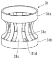
- annular ring portions 31 a and 31 b provided on one end side and the other end side are installed between the ring portions 31 a and 31 b and appropriately in the circumferential direction.
- a space portion 31d is formed between the curved portions 31c adjacent in the circumferential direction.
- the bending portion 31c is spaced apart from the axis XX toward the one end side and the other end side, and a cross section located at the axis side toward the center portion is formed in an arc shape. .
- the holding member 31 is accommodated in the accommodating portion 11 in the casing 10, and is accommodated in a connecting member 32 provided to be slidable in the axis XX direction.
- the connecting member 32 is formed with a storage space 32a that is open at both ends in the axis XX direction.
- the holding member 31 is stored in the storage space 32a, and the ring portion 31a on one end side of the holding member 31 is connected to the connecting member 32. 32 is fixed to the upper end of the inner peripheral surface.
- the other end side portion of the holding member 31 can move in the axis XX direction within the storage space 32a of the connecting member 32 as shown in FIGS.
- the holding member 31 is formed of a plate-like metal having elasticity, and a space portion 31d is formed between the curved portions 31c, and the cross section of the curved portion 31c is formed in an arc shape.
- the outer peripheral surface of the fuse cylinder 23 presses the curved portion 31c outward as shown in FIG. 30, and the curved portion 31c is in the direction of the axis XX.
- the bending portion 31c can elastically hold the fuse cylinder 23 by its restoring force.
- a pair of protrusions 32 b similar to the protrusions 18 b of the connection member 18 of the first embodiment are provided on the outer peripheral surface of the connection member 32 and are fitted in the mounting holes 20 a of the moving member 20.
- a holding member a holding having an annular base 41a and a plurality of protrusions 41b that protrude inward from the base 41a and are appropriately spaced in the circumferential direction.
- the member 41 may be used.
- the protrusion 41b has an inner peripheral surface located closer to the axis XX side toward the center of the cylindrical member 2 in the direction of the axis XX. It is formed in an arc shape that is separated from the shaft core XX.
- the holding member 41 is formed of a rubber material having elasticity.
- the holding member 41 is housed in the housing portion 11 in the tubular member 2 and is fixedly installed in a tubular connecting member 42 that is slidable in the axial direction XX.
- the holding member 41 is formed of an elastic rubber material or the like, and the inner peripheral surface of the protrusion 41b is formed in an arc shape that is located closer to the axis XX side toward the center in the axis XX direction.
- the connecting member 42 is provided with a pair of protrusions 42b similar to the protrusion 18b of the connecting member 18 of the first embodiment, and is fitted in the mounting hole 20a of the moving member 20.
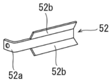
- a holding member 53 having a cylindrical main body 51 and an urging member 52 may be used as the holding member.
- a notch 51a penetrating inside and outside is formed in a part of the circumferential direction below the axis XX direction of the main body 51.
- an urging member 52 is provided across the notch 51a so as to be located on the inner side of the extension line of the inner peripheral surface of the main body 51.
- the urging member 52 is formed of a spring material and has a urging force that urges the cylindrical member 2 toward the axis XX, and only one end 52 a of the urging member 52 is the outer periphery of the main body 51.
- the urging member 52 is separated from the axial center XX as the distance from the base portion in the axial center XX direction on one end side and the other end side in the axial center XX direction of the casing 10 is increased.
- a tapered guide surface 52b that is spaced apart is formed.
- the urging member 52 is crimped to the fuse cylinder 23, and the fuse cylinder 23 is moved between the urging member 52 and the inner peripheral surface of the main body 51. It can be held.
- the number of the notches 51a and the urging members 52 may be provided as necessary in addition to the one shown in the drawing.
- a pair of protrusions 51b similar to the protrusions 18b of the connecting member 18 of the first embodiment are provided above the main body 51, and are fitted in the mounting holes 20a of the moving member 20.
- the force for holding the fuse cylinder 23 in the holding members 31, 41 and 53 is set to be weaker than the engaging force between the protrusion 23 a of the fuse cylinder 23 and the fuse cylinder holding member 25 of the cylindrical cutout 21.
- the holding members 31, 41, 53 are moved to the other end side of the casing 10 together with the moving member 20, and whether the fuse cylinder 23 is attached to the cylindrical cutout 21 or not. It can be easily distinguished from the ground.
- the position of the holding members 16, 31, 41, 53 can be confirmed by the position of the moving member 20 with respect to the casing 10, so that the cylindrical cutout 21 is used using the operation rod 1. It is possible to determine whether or not the fuse cylinder 23 is attached to the cylindrical cutout 21 when the fuse cylinder 23 is attached to the holding member 16, using any other means. You may comprise the confirmation means which can confirm the position of 31,41,53.
- the holding members 16, 31, 41, 53 do not hold the fuse cylinder 23, the holding members 16, 31, 41, 53 move to the other end side of the casing 10 due to their own weight, etc.
- the position is discriminated by a sensor, a switch or the like, a lamp provided at hand or the like is turned on, a sound is emitted from a speaker, a reflecting plate or the like protrudes outward from the casing 10, and the holding member 16, It may be possible to determine whether or not 31, 41, 53 is located on the other end side of the casing 10, and it may be a confirmation unit that can confirm the position of the holding members 16, 31, 41, 53 from the outside.
Landscapes
- Details Of Connecting Devices For Male And Female Coupling (AREA)
- Fuses (AREA)
Abstract
L'invention concerne une tige d'actionnement pouvant, dans une découpe cylindrique à une certaine hauteur du sol, déterminer facilement si un tube fusible est fixé dans la découpe. La tige d'actionnement (1) comporte : une enceinte (10) comprenant une section de contenance (11) qui est ouverte sur un côté d'extrémité, dans lequel au moins le tube fusible est inséré ; et un organe de rétention (16) qui peut coulisser dans la section de contenance (11) dans la direction axiale de l'enceinte (10) et qui peut retenir de manière amovible le tube fusible, tel que, dans des cas où le tube fusible est fixé à la découpe cylindrique au moyen de la tige d'actionnement, dans un état dans lequel l'organe de rétention (16) retient le tube fusible, l'organe de rétention (16) est positionné sur ledit côté d'extrémité et, dans un état dans lequel l'organe de rétention (16) ne retient pas le tube fusible, l'organe de rétention (16) est positionné sur l'autre côté d'extrémité, et comporte un moyen de confirmation (29) pouvant confirmer la position de l'organe de rétention (16).
Priority Applications (2)
| Application Number | Priority Date | Filing Date | Title |
|---|---|---|---|
| CN201680076600.3A CN108496237B (zh) | 2016-01-18 | 2016-01-18 | 操作棒 |
| PCT/JP2016/051235 WO2017125997A1 (fr) | 2016-01-18 | 2016-01-18 | Tige d'actionnement |
Applications Claiming Priority (1)
| Application Number | Priority Date | Filing Date | Title |
|---|---|---|---|
| PCT/JP2016/051235 WO2017125997A1 (fr) | 2016-01-18 | 2016-01-18 | Tige d'actionnement |
Publications (1)
| Publication Number | Publication Date |
|---|---|
| WO2017125997A1 true WO2017125997A1 (fr) | 2017-07-27 |
Family
ID=59361960
Family Applications (1)
| Application Number | Title | Priority Date | Filing Date |
|---|---|---|---|
| PCT/JP2016/051235 Ceased WO2017125997A1 (fr) | 2016-01-18 | 2016-01-18 | Tige d'actionnement |
Country Status (2)
| Country | Link |
|---|---|
| CN (1) | CN108496237B (fr) |
| WO (1) | WO2017125997A1 (fr) |
Cited By (1)
| Publication number | Priority date | Publication date | Assignee | Title |
|---|---|---|---|---|
| CN112670138A (zh) * | 2019-10-15 | 2021-04-16 | 爱那其斯株式会社 | 操作棒 |
Families Citing this family (1)
| Publication number | Priority date | Publication date | Assignee | Title |
|---|---|---|---|---|
| TWI867818B (zh) * | 2023-10-31 | 2024-12-21 | 國立彰化師範大學 | 高壓熔絲鏈復電裝置 |
Citations (2)
| Publication number | Priority date | Publication date | Assignee | Title |
|---|---|---|---|---|
| JPH10269926A (ja) * | 1997-03-27 | 1998-10-09 | Ngk Insulators Ltd | 円筒形カットアウト用ヒューズ筒 |
| JP2014099333A (ja) * | 2012-11-14 | 2014-05-29 | Chugoku Electric Power Co Inc:The | 円筒形カットアウト |
Family Cites Families (5)
| Publication number | Priority date | Publication date | Assignee | Title |
|---|---|---|---|---|
| CN202018938U (zh) * | 2011-04-28 | 2011-10-26 | 上海市电力公司 | 一种熔丝管操作棒 |
| CN202150431U (zh) * | 2011-07-07 | 2012-02-22 | 日本能源服务株式会社 | 高压熔断器的复原确认装置 |
| CN202225102U (zh) * | 2011-09-16 | 2012-05-23 | 上海市电力公司 | 一种夹3a熔丝专用工具钳 |
| CN203026475U (zh) * | 2013-01-08 | 2013-06-26 | 王阳 | 一种环网柜高压熔断器更换操作杆 |
| CN203573838U (zh) * | 2013-11-20 | 2014-04-30 | 国家电网公司 | 一种验电型绝缘操作棒 |
-
2016
- 2016-01-18 CN CN201680076600.3A patent/CN108496237B/zh active Active
- 2016-01-18 WO PCT/JP2016/051235 patent/WO2017125997A1/fr not_active Ceased
Patent Citations (2)
| Publication number | Priority date | Publication date | Assignee | Title |
|---|---|---|---|---|
| JPH10269926A (ja) * | 1997-03-27 | 1998-10-09 | Ngk Insulators Ltd | 円筒形カットアウト用ヒューズ筒 |
| JP2014099333A (ja) * | 2012-11-14 | 2014-05-29 | Chugoku Electric Power Co Inc:The | 円筒形カットアウト |
Cited By (1)
| Publication number | Priority date | Publication date | Assignee | Title |
|---|---|---|---|---|
| CN112670138A (zh) * | 2019-10-15 | 2021-04-16 | 爱那其斯株式会社 | 操作棒 |
Also Published As
| Publication number | Publication date |
|---|---|
| CN108496237B (zh) | 2019-05-21 |
| CN108496237A (zh) | 2018-09-04 |
Similar Documents
| Publication | Publication Date | Title |
|---|---|---|
| JP6041189B2 (ja) | スナップリングの装着冶具 | |
| JP6110499B2 (ja) | 長尺要素の案内及び位置確保のためのシステム | |
| KR102807715B1 (ko) | 팽이 완구 | |
| JP2010131726A (ja) | 工具用ソケット | |
| JP2015183851A (ja) | 差込継手部材 | |
| JP2006267649A (ja) | 光コネクタ | |
| TW201723550A (zh) | 內建連接器的插頭 | |
| JP2013238286A (ja) | クリップ | |
| JP2005178499A (ja) | シフトレバー装置 | |
| JP6687660B2 (ja) | シール装着装置およびシール装着方法 | |
| US20130193281A1 (en) | Releasable locking connector | |
| JP2012240155A (ja) | スナップリング取付用工具 | |
| JP5836640B2 (ja) | スプリンクラーヘッド着脱用レンチ | |
| JP2017159420A (ja) | 工具用ソケット | |
| JP6133665B2 (ja) | ボルト用キャップ | |
| JP7151584B2 (ja) | グロメット | |
| CN105679608B (zh) | 电磁开关及车辆起动机 | |
| JP2020193655A (ja) | ガスケット | |
| KR20180118950A (ko) | 콘크리트 파일 거푸집용 고정구 | |
| JP6510973B2 (ja) | 回転工具及びそれに用いる工具用ソケット | |
| JP2014101894A (ja) | センサ取付具 | |
| JP6041956B2 (ja) | スプリンクラーヘッド着脱用レンチ | |
| WO2017126113A1 (fr) | Instrument de fixation | |
| JPH11241512A (ja) | 鉄筋保護キャップ | |
| JP6418087B2 (ja) | クリップ取付治具 |
Legal Events
| Date | Code | Title | Description |
|---|---|---|---|
| 121 | Ep: the epo has been informed by wipo that ep was designated in this application |
Ref document number: 16886240 Country of ref document: EP Kind code of ref document: A1 |
|
| NENP | Non-entry into the national phase |
Ref country code: DE |
|
| 122 | Ep: pct application non-entry in european phase |
Ref document number: 16886240 Country of ref document: EP Kind code of ref document: A1 |
|
| NENP | Non-entry into the national phase |
Ref country code: JP |