WO2017126475A1 - Dispositif et procédé de commande pour véhicule - Google Patents
Dispositif et procédé de commande pour véhicule Download PDFInfo
- Publication number
- WO2017126475A1 WO2017126475A1 PCT/JP2017/001255 JP2017001255W WO2017126475A1 WO 2017126475 A1 WO2017126475 A1 WO 2017126475A1 JP 2017001255 W JP2017001255 W JP 2017001255W WO 2017126475 A1 WO2017126475 A1 WO 2017126475A1
- Authority
- WO
- WIPO (PCT)
- Prior art keywords
- vehicle
- control
- completed
- downshift
- variator
- Prior art date
- Legal status (The legal status is an assumption and is not a legal conclusion. Google has not performed a legal analysis and makes no representation as to the accuracy of the status listed.)
- Ceased
Links
Images

Classifications
-
- F—MECHANICAL ENGINEERING; LIGHTING; HEATING; WEAPONS; BLASTING
- F16—ENGINEERING ELEMENTS AND UNITS; GENERAL MEASURES FOR PRODUCING AND MAINTAINING EFFECTIVE FUNCTIONING OF MACHINES OR INSTALLATIONS; THERMAL INSULATION IN GENERAL
- F16H—GEARING
- F16H63/00—Control outputs from the control unit to change-speed- or reversing-gearings for conveying rotary motion or to other devices than the final output mechanism
- F16H63/40—Control outputs from the control unit to change-speed- or reversing-gearings for conveying rotary motion or to other devices than the final output mechanism comprising signals other than signals for actuating the final output mechanisms
- F16H63/46—Signals to a clutch outside the gearbox
-
- F—MECHANICAL ENGINEERING; LIGHTING; HEATING; WEAPONS; BLASTING
- F16—ENGINEERING ELEMENTS AND UNITS; GENERAL MEASURES FOR PRODUCING AND MAINTAINING EFFECTIVE FUNCTIONING OF MACHINES OR INSTALLATIONS; THERMAL INSULATION IN GENERAL
- F16H—GEARING
- F16H59/00—Control inputs to control units of change-speed- or reversing-gearings for conveying rotary motion
- F16H59/14—Inputs being a function of torque or torque demand
- F16H59/18—Inputs being a function of torque or torque demand dependent on the position of the accelerator pedal
-
- F—MECHANICAL ENGINEERING; LIGHTING; HEATING; WEAPONS; BLASTING
- F16—ENGINEERING ELEMENTS AND UNITS; GENERAL MEASURES FOR PRODUCING AND MAINTAINING EFFECTIVE FUNCTIONING OF MACHINES OR INSTALLATIONS; THERMAL INSULATION IN GENERAL
- F16H—GEARING
- F16H61/00—Control functions within control units of change-speed- or reversing-gearings for conveying rotary motion ; Control of exclusively fluid gearing, friction gearing, gearings with endless flexible members or other particular types of gearing
- F16H61/0021—Generation or control of line pressure
- F16H61/0025—Supply of control fluid; Pumps therefor
- F16H61/0031—Supply of control fluid; Pumps therefor using auxiliary pumps, e.g. pump driven by a different power source than the engine
-
- F—MECHANICAL ENGINEERING; LIGHTING; HEATING; WEAPONS; BLASTING
- F16—ENGINEERING ELEMENTS AND UNITS; GENERAL MEASURES FOR PRODUCING AND MAINTAINING EFFECTIVE FUNCTIONING OF MACHINES OR INSTALLATIONS; THERMAL INSULATION IN GENERAL
- F16H—GEARING
- F16H61/00—Control functions within control units of change-speed- or reversing-gearings for conveying rotary motion ; Control of exclusively fluid gearing, friction gearing, gearings with endless flexible members or other particular types of gearing
- F16H61/02—Control functions within control units of change-speed- or reversing-gearings for conveying rotary motion ; Control of exclusively fluid gearing, friction gearing, gearings with endless flexible members or other particular types of gearing characterised by the signals used
- F16H61/0202—Control functions within control units of change-speed- or reversing-gearings for conveying rotary motion ; Control of exclusively fluid gearing, friction gearing, gearings with endless flexible members or other particular types of gearing characterised by the signals used the signals being electric
- F16H61/0204—Control functions within control units of change-speed- or reversing-gearings for conveying rotary motion ; Control of exclusively fluid gearing, friction gearing, gearings with endless flexible members or other particular types of gearing characterised by the signals used the signals being electric for gearshift control, e.g. control functions for performing shifting or generation of shift signal
- F16H61/0213—Control functions within control units of change-speed- or reversing-gearings for conveying rotary motion ; Control of exclusively fluid gearing, friction gearing, gearings with endless flexible members or other particular types of gearing characterised by the signals used the signals being electric for gearshift control, e.g. control functions for performing shifting or generation of shift signal characterised by the method for generating shift signals
-
- F—MECHANICAL ENGINEERING; LIGHTING; HEATING; WEAPONS; BLASTING
- F16—ENGINEERING ELEMENTS AND UNITS; GENERAL MEASURES FOR PRODUCING AND MAINTAINING EFFECTIVE FUNCTIONING OF MACHINES OR INSTALLATIONS; THERMAL INSULATION IN GENERAL
- F16H—GEARING
- F16H61/00—Control functions within control units of change-speed- or reversing-gearings for conveying rotary motion ; Control of exclusively fluid gearing, friction gearing, gearings with endless flexible members or other particular types of gearing
- F16H61/02—Control functions within control units of change-speed- or reversing-gearings for conveying rotary motion ; Control of exclusively fluid gearing, friction gearing, gearings with endless flexible members or other particular types of gearing characterised by the signals used
- F16H61/0202—Control functions within control units of change-speed- or reversing-gearings for conveying rotary motion ; Control of exclusively fluid gearing, friction gearing, gearings with endless flexible members or other particular types of gearing characterised by the signals used the signals being electric
- F16H61/0204—Control functions within control units of change-speed- or reversing-gearings for conveying rotary motion ; Control of exclusively fluid gearing, friction gearing, gearings with endless flexible members or other particular types of gearing characterised by the signals used the signals being electric for gearshift control, e.g. control functions for performing shifting or generation of shift signal
- F16H61/0246—Control functions within control units of change-speed- or reversing-gearings for conveying rotary motion ; Control of exclusively fluid gearing, friction gearing, gearings with endless flexible members or other particular types of gearing characterised by the signals used the signals being electric for gearshift control, e.g. control functions for performing shifting or generation of shift signal characterised by initiating reverse gearshift
-
- F—MECHANICAL ENGINEERING; LIGHTING; HEATING; WEAPONS; BLASTING
- F16—ENGINEERING ELEMENTS AND UNITS; GENERAL MEASURES FOR PRODUCING AND MAINTAINING EFFECTIVE FUNCTIONING OF MACHINES OR INSTALLATIONS; THERMAL INSULATION IN GENERAL
- F16H—GEARING
- F16H61/00—Control functions within control units of change-speed- or reversing-gearings for conveying rotary motion ; Control of exclusively fluid gearing, friction gearing, gearings with endless flexible members or other particular types of gearing
- F16H61/02—Control functions within control units of change-speed- or reversing-gearings for conveying rotary motion ; Control of exclusively fluid gearing, friction gearing, gearings with endless flexible members or other particular types of gearing characterised by the signals used
- F16H61/0262—Control functions within control units of change-speed- or reversing-gearings for conveying rotary motion ; Control of exclusively fluid gearing, friction gearing, gearings with endless flexible members or other particular types of gearing characterised by the signals used the signals being hydraulic
- F16H61/0265—Control functions within control units of change-speed- or reversing-gearings for conveying rotary motion ; Control of exclusively fluid gearing, friction gearing, gearings with endless flexible members or other particular types of gearing characterised by the signals used the signals being hydraulic for gearshift control, e.g. control functions for performing shifting or generation of shift signals
- F16H61/0267—Layout of hydraulic control circuits, e.g. arrangement of valves
-
- F—MECHANICAL ENGINEERING; LIGHTING; HEATING; WEAPONS; BLASTING
- F16—ENGINEERING ELEMENTS AND UNITS; GENERAL MEASURES FOR PRODUCING AND MAINTAINING EFFECTIVE FUNCTIONING OF MACHINES OR INSTALLATIONS; THERMAL INSULATION IN GENERAL
- F16H—GEARING
- F16H61/00—Control functions within control units of change-speed- or reversing-gearings for conveying rotary motion ; Control of exclusively fluid gearing, friction gearing, gearings with endless flexible members or other particular types of gearing
- F16H61/04—Smoothing ratio shift
-
- B—PERFORMING OPERATIONS; TRANSPORTING
- B60—VEHICLES IN GENERAL
- B60W—CONJOINT CONTROL OF VEHICLE SUB-UNITS OF DIFFERENT TYPE OR DIFFERENT FUNCTION; CONTROL SYSTEMS SPECIALLY ADAPTED FOR HYBRID VEHICLES; ROAD VEHICLE DRIVE CONTROL SYSTEMS FOR PURPOSES NOT RELATED TO THE CONTROL OF A PARTICULAR SUB-UNIT
- B60W10/00—Conjoint control of vehicle sub-units of different type or different function
- B60W10/04—Conjoint control of vehicle sub-units of different type or different function including control of propulsion units
- B60W10/06—Conjoint control of vehicle sub-units of different type or different function including control of propulsion units including control of combustion engines
-
- B—PERFORMING OPERATIONS; TRANSPORTING
- B60—VEHICLES IN GENERAL
- B60W—CONJOINT CONTROL OF VEHICLE SUB-UNITS OF DIFFERENT TYPE OR DIFFERENT FUNCTION; CONTROL SYSTEMS SPECIALLY ADAPTED FOR HYBRID VEHICLES; ROAD VEHICLE DRIVE CONTROL SYSTEMS FOR PURPOSES NOT RELATED TO THE CONTROL OF A PARTICULAR SUB-UNIT
- B60W20/00—Control systems specially adapted for hybrid vehicles
- B60W20/30—Control strategies involving selection of transmission gear ratio
-
- B—PERFORMING OPERATIONS; TRANSPORTING
- B60—VEHICLES IN GENERAL
- B60W—CONJOINT CONTROL OF VEHICLE SUB-UNITS OF DIFFERENT TYPE OR DIFFERENT FUNCTION; CONTROL SYSTEMS SPECIALLY ADAPTED FOR HYBRID VEHICLES; ROAD VEHICLE DRIVE CONTROL SYSTEMS FOR PURPOSES NOT RELATED TO THE CONTROL OF A PARTICULAR SUB-UNIT
- B60W2540/00—Input parameters relating to occupants
- B60W2540/10—Accelerator pedal position
-
- F—MECHANICAL ENGINEERING; LIGHTING; HEATING; WEAPONS; BLASTING
- F16—ENGINEERING ELEMENTS AND UNITS; GENERAL MEASURES FOR PRODUCING AND MAINTAINING EFFECTIVE FUNCTIONING OF MACHINES OR INSTALLATIONS; THERMAL INSULATION IN GENERAL
- F16H—GEARING
- F16H59/00—Control inputs to control units of change-speed- or reversing-gearings for conveying rotary motion
- F16H59/14—Inputs being a function of torque or torque demand
- F16H59/18—Inputs being a function of torque or torque demand dependent on the position of the accelerator pedal
- F16H2059/186—Coasting
-
- F—MECHANICAL ENGINEERING; LIGHTING; HEATING; WEAPONS; BLASTING
- F16—ENGINEERING ELEMENTS AND UNITS; GENERAL MEASURES FOR PRODUCING AND MAINTAINING EFFECTIVE FUNCTIONING OF MACHINES OR INSTALLATIONS; THERMAL INSULATION IN GENERAL
- F16H—GEARING
- F16H61/00—Control functions within control units of change-speed- or reversing-gearings for conveying rotary motion ; Control of exclusively fluid gearing, friction gearing, gearings with endless flexible members or other particular types of gearing
- F16H61/04—Smoothing ratio shift
- F16H2061/0496—Smoothing ratio shift for low engine torque, e.g. during coasting, sailing or engine braking
-
- F—MECHANICAL ENGINEERING; LIGHTING; HEATING; WEAPONS; BLASTING
- F16—ENGINEERING ELEMENTS AND UNITS; GENERAL MEASURES FOR PRODUCING AND MAINTAINING EFFECTIVE FUNCTIONING OF MACHINES OR INSTALLATIONS; THERMAL INSULATION IN GENERAL
- F16H—GEARING
- F16H61/00—Control functions within control units of change-speed- or reversing-gearings for conveying rotary motion ; Control of exclusively fluid gearing, friction gearing, gearings with endless flexible members or other particular types of gearing
- F16H61/66—Control functions within control units of change-speed- or reversing-gearings for conveying rotary motion ; Control of exclusively fluid gearing, friction gearing, gearings with endless flexible members or other particular types of gearing specially adapted for continuously variable gearings
- F16H2061/6601—Control functions within control units of change-speed- or reversing-gearings for conveying rotary motion ; Control of exclusively fluid gearing, friction gearing, gearings with endless flexible members or other particular types of gearing specially adapted for continuously variable gearings with arrangements for dividing torque and shifting between different ranges
Definitions
- the present invention relates to a vehicle control device and a vehicle control method.
- JP2013-213557 discloses a vehicle control system that performs so-called sailing stop control in which a clutch is disengaged and the automatic transmission is in a neutral state (power cut-off state) when the predetermined condition is satisfied, and the vehicle is driven with the drive source stopped.
- An apparatus is disclosed.
- the driver intends to accelerate.
- the sailing stop control is canceled, it is desirable to downshift the continuously variable transmission.
- the continuously variable transmission is downshifted after the sailing stop control is canceled and the automatic transmission is in the power transmission state, the acceleration of the vehicle may be reduced.
- an object of the present invention is to ensure acceleration when releasing the neutral travel control.
- An aspect of the present invention provides a vehicle control device that controls a vehicle including an automatic transmission having a power transmission mechanism having a fastening element and a variator connected in series to the power transmission mechanism.
- a vehicle control device that controls a vehicle including an automatic transmission having a power transmission mechanism having a fastening element and a variator connected in series to the power transmission mechanism.
- the fastening element A control unit for completing the fastening is provided.
- a vehicle control method for controlling a vehicle including an automatic transmission having a power transmission mechanism having a fastening element and a variator connected in series to the power transmission mechanism. To do.
- the fastening element Complete the fastening.
- the fastening of the fastening element is completed after the downshift of the variator is completed. Acceleration can be ensured.
- FIG. 1 is a schematic configuration diagram of a vehicle according to an embodiment of the present invention.
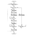
- FIG. 2 is a flowchart for canceling the sailing stop control in the embodiment.
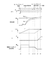
- FIG. 3 is a time chart when the sailing stop control is canceled in the embodiment.
- the gear ratio is a value obtained by dividing the rotational speed of the input shaft of the continuously variable transmission by the rotational speed of the output shaft of the continuously variable transmission.
- the gear ratio is on the low side.
- the gear ratio is small, it is said that the gear ratio is on the High side.
- increasing the transmission ratio of the continuously variable transmission is called “downshift”, and decreasing the transmission ratio is called “upshift”.
- FIG. 1 is a schematic configuration diagram of a vehicle according to the present embodiment.
- the vehicle includes an engine 1, a torque converter 2, a forward / reverse switching mechanism 3 that is a power transmission mechanism, a continuously variable transmission (variator) 4, a hydraulic control circuit 5, a machine-driven oil pump (hereinafter referred to as “mechanism”). 6m), an electric oil pump 6e, an engine controller 10, and a transmission controller 11.
- the rotation generated by the engine 1 is transmitted to drive wheels (not shown) via the torque converter 2, the forward / reverse switching mechanism 3, the continuously variable transmission 4, the gear set 8, and the differential gear device 9.
- the forward / reverse switching mechanism 3 and the continuously variable transmission 4 constitute an automatic transmission 15.
- the torque converter 2 has a lockup clutch 2a.
- the lockup clutch 2a When the lockup clutch 2a is engaged, the input shaft and the output shaft of the torque converter 2 are directly connected, and the input shaft and the output shaft rotate at the same speed. .
- the forward / reverse switching mechanism 3 includes a double pinion planetary gear set as a main component, and the sun gear is coupled to the engine 1 via the torque converter 2 and the carrier is coupled to the primary pulley 4a.
- the forward / reverse switching mechanism 3 further includes a forward clutch 3a that directly connects the sun gear of the double pinion planetary gear set and the carrier, and a reverse brake 3b that fixes the ring gear, and from the engine 1 via the torque converter 2 when the forward clutch 3a is engaged.
- the input rotation is transmitted to the primary pulley 4a as it is, and when the reverse brake 3b is engaged, the input rotation via the torque converter 2 from the engine 1 is transmitted to the primary pulley 4a under reverse deceleration.
- the states of the forward clutch 3a and the reverse brake 3b include “released”, “standby”, “slip”, and “engaged” states. These states are switched according to the hydraulic pressure supplied to each piston pressure receiving chamber.
- Release is a state in which, for example, hydraulic pressure is not supplied to the forward clutch 3a, and the forward clutch 3a has no torque capacity.
- “Standby” is a state in which, for example, hydraulic pressure is supplied to the forward clutch 3a, but the forward clutch 3a has no torque capacity. In the “standby” state, the forward clutch 3a is in a state immediately before having a torque capacity.
- the “slip” is, for example, a forward / reverse switching mechanism when hydraulic pressure is supplied to the forward clutch 3a, the forward clutch 3a has torque capacity, and the forward clutch 3a is fastened between the input and output shafts of the forward / reverse switching mechanism 3.
- 3 is a state in which a rotational speed difference taking into consideration a transmission gear ratio R1 of 3 is generated. In the “sliding” state, the torque capacity is smaller than the input torque of the forward clutch 3a.
- the “engaged” means, for example, a forward / reverse switching mechanism when hydraulic pressure is supplied to the forward clutch 3a, the forward clutch 3a has a torque capacity, and the forward clutch 3a is engaged between the input / output shafts of the forward / reverse switching mechanism 3.
- This is a state in which a rotational speed difference in consideration of the gear ratio R1 of 3 has not occurred.
- the torque capacity is larger than the input torque of the forward clutch 3a.
- the “engaged” state includes complete engagement in which the torque capacity is further increased after the torque capacity becomes larger than the input torque of the forward clutch 3a, and the torque capacity has a margin for the input torque.
- the continuously variable transmission 4 includes a primary pulley 4a, a secondary pulley 4b, and a belt 4c.
- the continuously variable transmission 4 by controlling the hydraulic pressure supplied to the primary pulley 4a and the hydraulic pressure supplied to the secondary pulley 4b, the contact radius between the pulleys 4a, 4b and the belt 4c is changed.
- the transmission ratio I of the step transmission 4 (variator) is changed.
- the mechanical oil pump 6m is a mechanical oil pump that receives rotation of the engine 1 and is driven by using a part of the power of the engine 1.
- the oil discharged from the mechanical oil pump 6m is supplied to the hydraulic control circuit 5 by driving the mechanical oil pump 6m.
- engine 1 is stopped, mechanical oil pump 6m is not driven, and no oil is discharged from mechanical oil pump 6m.
- the electric oil pump 6e is an electric oil pump that is driven by power supplied from a battery. By driving the electric oil pump 6e when the mechanical oil pump 6m is not driven, oil can be supplied to the hydraulic control circuit 5 even when the engine is stopped.
- the hydraulic control circuit 5 includes a plurality of flow paths and a plurality of hydraulic actuators.
- the hydraulic actuator includes a solenoid and a hydraulic control valve.
- the hydraulic actuator is controlled based on the control signal from the transmission controller 11, the hydraulic supply path is switched, and the line pressure generated by the oil discharged from the mechanical oil pump 6m and the electric oil pump 6e.
- the necessary hydraulic pressure is adjusted from The hydraulic control circuit 5 supplies the adjusted hydraulic pressure to each part of the continuously variable transmission 4, the forward / reverse switching mechanism 3, and the torque converter 2.
- the transmission controller 11 includes a CPU, a ROM, a RAM, and the like, and controls the operation of the automatic transmission 15.
- the function of the transmission controller 11 is exhibited by the CPU reading and executing a program stored in the ROM.
- the transmission controller 11 detects a signal from the accelerator pedal opening sensor 21 that detects the accelerator pedal opening APO corresponding to the operation amount of the accelerator pedal 41, and a brake fluid pressure BRP corresponding to the operation amount of the brake pedal 42. A signal from the brake fluid pressure sensor 22 and a signal from the inhibitor switch 23 for detecting the position of the shift lever 40 are input.
- the transmission controller 11 also includes a signal from the input side rotational speed sensor 24 that detects the rotational speed Nin on the input side (engine 1 side) of the forward / reverse switching mechanism 3, and an output side (continuously variable).
- the signal from the output side rotational speed sensor 25 that detects the rotational speed Nout of the transmission 4 side the signal from the vehicle speed sensor 26 that detects the vehicle speed VSP, and the engine torque Te from the engine controller 10 that controls the operation of the engine 1. Signal is input.
- Sailing stop conditions are, for example, the following conditions.
- the shift lever 40 is in the D range.
- the vehicle speed VSP is equal to or higher than the first predetermined vehicle speed V1.
- the accelerator pedal 41 is not depressed.
- the brake pedal 42 is not depressed.
- the first predetermined vehicle speed V1 is a medium or high vehicle speed and is set in advance.
- the sailing stop condition is satisfied when all of the above conditions (a) to (d) are satisfied, and is not satisfied when any of the above (a) to (d) is not satisfied.
- the sailing stop condition is also a sailing stop cancellation condition for canceling the sailing stop control.
- the sailing stop condition and the sailing stop cancellation condition may be different conditions.
- the engine 1 When the sailing stop cancellation condition is satisfied, the engine 1 is started and the forward clutch 3a is engaged, and then normal traveling control is executed. Between the time when the sailing stop cancellation condition is satisfied and the time when the normal traveling control is executed, the forward clutch 3a is engaged after the rotation synchronization control for starting the engine 1 and synchronizing the rotational speeds before and after the forward clutch 3a is performed. Sailing stop cancellation control is executed. Sailing stop control, rotation synchronization control, sailing stop release control, and the like are executed by the transmission controller 11 and the engine controller 10.
- the forward / reverse switching mechanism 3 is in a power cut-off state, and the automatic transmission 15 is in a neutral state. Further, since the engine 1 is stopped, the mechanical oil pump 6m is not driven. Therefore, during the sailing stop control, the necessary hydraulic pressure is supplied to the vehicle using the oil discharged from the electric oil pump 6e.
- step S100 the transmission controller 11 determines whether a sailing stop cancellation condition (SS cancellation condition) is satisfied. Specifically, the transmission controller 11 determines whether any of the above (a) to (d) is not satisfied. If the sailing stop cancellation condition is satisfied, the process proceeds to step S101. If the sailing stop cancellation condition is not satisfied, the current process ends.
- SS cancellation condition a sailing stop cancellation condition
- step S101 the transmission controller 11 determines whether or not the accelerator pedal opening APO is equal to or greater than a predetermined opening APO1.
- the accelerator pedal opening APO is detected based on a signal from the accelerator pedal opening sensor 21.
- the predetermined opening APO1 is a preset opening and is a value larger than zero.
- the predetermined opening APO1 is an opening at which it can be determined that the driver's intention to accelerate is large. If the accelerator pedal opening APO is greater than or equal to the predetermined opening APO1, the process proceeds to step S102. On the other hand, if the accelerator pedal opening APO is less than the predetermined opening APO1, the process proceeds to step S109.
- the accelerator pedal opening APO may include a value corresponding to the throttle opening TVO. That is, the accelerator pedal opening APO includes the throttle opening TVO.
- step S102 the transmission controller 11 controls the electric oil pump 6e, increases the rotational speed of the electric oil pump 6e, and increases the discharge amount of the electric oil pump 6e.
- the electric oil pump 6e When the accelerator pedal opening APO is less than the predetermined opening APO1 and the driver's intention to accelerate is small, the electric oil pump 6e does not cause belt slip in the continuously variable transmission 4, and does not require oil for lubrication or the like. It is controlled to discharge. On the other hand, when the accelerator pedal opening APO is equal to or greater than the predetermined opening APO1 and the driver's intention to accelerate is large, the continuously variable transmission 4 is downshifted as will be described later. The quantity, that is, the oil balance increases. Therefore, the transmission controller 11 increases the rotational speed of the electric oil pump 6e and increases the discharge amount of the electric oil pump 6e.
- step S103 the transmission controller 11 starts a downshift of the continuously variable transmission 4.
- step S104 the engine controller 10 starts the engine 1 and starts rotation synchronization control.
- step S105 the transmission controller 11 determines whether or not the continuously variable transmission 4 is downshifted and the transmission gear ratio I of the continuously variable transmission 4 reaches a predetermined transmission gear ratio I1.
- the gear ratio I is calculated based on the signal from the output side rotational speed sensor 25 and the signal from the vehicle speed sensor 26.
- the predetermined speed ratio I1 is a speed ratio set in advance, and is set based on, for example, the accelerator pedal opening APO. When the accelerator pedal opening APO is large, it is considered that the driver wants to accelerate quickly. For this reason, it is desired that the gear ratio I of the continuously variable transmission 4 is set to the Low side. If the continuously variable transmission 4 reaches the predetermined speed ratio I1, the process proceeds to step S106.
- step S106 the transmission controller 11 ends the downshift of the continuously variable transmission 4.
- step S107 the transmission controller 11 controls the electric oil pump 6e, decreases the rotational speed of the electric oil pump 6e, and decreases the discharge amount of the electric oil pump 6e. Specifically, the discharge amount is decreased by the amount of oil necessary for downshifting the continuously variable transmission 4, that is, the discharge amount increased in step S102.
- step S108 the transmission controller 11 determines whether the rotation of the forward clutch 3a is synchronized. Specifically, the transmission controller 11 determines whether or not the relationship between the rotational speed Nin on the input side of the forward / reverse switching mechanism 3 and the rotational speed Nout on the output side of the forward / reverse switching mechanism 3 satisfies Expression (1). To do.
- R1 is the gear ratio of the forward / reverse switching mechanism 3 when the forward clutch 3a is engaged.
- N1 is a threshold value set in advance, and is a value that can be determined that the occurrence of engagement shock can be suppressed when the forward clutch 3a is engaged.
- the transmission controller 11 determines that the rotation is synchronized when the expression (1) is satisfied, and determines that the rotation is not synchronized when the expression (1) is not satisfied. If it is determined that the rotational speed Nin on the input side is increased by the start of the engine 1 and the rotation is synchronized, the process proceeds to step S111.
- equation (2) or the like may be used instead of equation (1).
- N2 is a threshold value set in advance, and is a value that can be determined that the occurrence of the engagement shock can be suppressed when the forward clutch 3a is engaged.
- step S109 the engine controller 10 starts the engine 1 and starts rotation synchronization control.
- step S101 when the accelerator pedal opening APO is less than the predetermined opening APO1, it is determined that the driver's intention to accelerate is small. Therefore, in step S109, the rotation synchronization control is started without starting the downshift by the continuously variable transmission 4.
- step S110 the transmission controller 11 determines whether the rotation is synchronized in the forward / reverse switching mechanism 3. The determination method is the same as in step S108. If it is determined that the rotation is synchronized, the process proceeds to step S111.
- step S111 the transmission controller 11 ends the rotation synchronization control, and executes the sailing stop cancellation control.
- the transmission controller 11 increases the hydraulic pressure supplied to the forward clutch 3a and fastens the forward clutch 3a.
- the solid line indicates the case where the accelerator pedal opening APO is equal to or greater than the predetermined opening APO1
- the broken line indicates the case where the accelerator pedal opening APO is less than the predetermined opening APO1.
- Sailing stop control is executed before time t0.
- the rotational speed of the electric oil pump 6e is lowered without changing the gear ratio I of the continuously variable transmission 4. Thereby, the power consumption of the electric oil pump 6e during sailing stop control can be suppressed, and the power consumption can be improved.
- the accelerator pedal 41 is depressed, the sailing stop control release condition is satisfied, and the rotation synchronization control is started.
- the engine 1 is started and the rotational speed Nin on the input side increases.
- the rotational speed of the electric oil pump 6e is increased in order to supply standby pressure to the forward clutch 3a as a preparation stage for quickly engaging the forward clutch 3a, for example.
- the rotation synchronization control is finished, and the forward clutch 3a can be quickly engaged when the forward clutch 3a is engaged.
- the forward clutch 3a is engaged, the sailing stop release control is terminated, the normal traveling control is started, and the continuously variable transmission 4 is downshifted.
- the rotational speed of the electric oil pump 6e is gradually reduced, and the continuously variable transmission 4 is downshifted mainly using oil discharged from the mechanical oil pump 6m.
- the rotational speed of the electric oil pump 6e can be made zero in a stepwise manner.
- the engine 1 is starting up and is not limited to the oil discharged from the mechanical oil pump 6m.
- the hydraulic pressure necessary to downshift the step transmission 4 cannot be generated. Therefore, by gradually reducing the rotational speed of the electric oil pump 6e, it is possible to suppress a shortage of hydraulic pressure supplied to the continuously variable transmission 4, and to reliably downshift the continuously variable transmission 4.
- the accelerator pedal 41 is depressed, the sailing stop control release condition is satisfied, and the rotation synchronization control is started.
- the engine 1 is started and the rotational speed Nin on the input side increases.
- the continuously variable transmission 4 is lowered using the oil discharged from the electric oil pump 6e. Shift is possible.
- the continuously variable transmission 4 is downshifted using the oil discharged from the electric oil pump 6e, and the gear ratio I is changed to the Low side.
- the rotational speed Nout on the output side of the forward / reverse switching mechanism 3 increases.
- the continuously variable transmission 4 is downshifted, and the rotational speed Nout on the output side of the forward / reverse switching mechanism 3 is increased. Therefore, compared with the case where the accelerator pedal opening APO is less than the predetermined opening APO1, the engagement of the forward clutch 3a is completed and the timing at which the traveling control is started is delayed.
- the forward clutch 3a When the conditions for canceling the sailing stop control are satisfied, the accelerator pedal opening APO is equal to or greater than the predetermined opening APO1, and the driver's acceleration request is large, the forward clutch 3a is turned on after the downshift of the continuously variable transmission 4 is completed. Complete the fastening. Thereby, when the forward clutch 3a is engaged, the transmission gear ratio I of the continuously variable transmission 4 is low, so that the acceleration performance of the vehicle is improved and the acceleration response of the vehicle can be improved.
- the accelerator pedal opening APO is less than the predetermined opening APO1, and the driver's acceleration request is small, the continuously variable transmission 4 is lowered after the engagement of the forward clutch 3a is completed. Complete the shift. Thereby, the hydraulic pressure balance at the time of canceling sailing stop control can be decreased, and it can control that the rotation speed of electric oil pump 6e becomes high. Therefore, the power consumption in the electric oil pump 6e can be suppressed and the power consumption can be improved.
- the downshift of the continuously variable transmission 4 is completed after the fastening of the forward clutch 3a is completed.
- the rotational speed of the electric oil pump 6e is made higher than when the operation is completed.
- the fuel consumption can be improved by stopping the engine 1.
- the sailing stop control cancellation condition is satisfied, the engine 1 is started, so that the oil amount required for the vehicle can be covered by using the oil discharged from the mechanical oil pump 6m.
- the accelerator pedal opening APO is equal to or greater than the predetermined opening APO1
- the continuously variable transmission 4 is downshifted using the oil discharged from the electric oil pump 6e.
- the accelerator pedal opening APO is compared with the predetermined opening APO1, and it is determined that the driver intends to accelerate when the accelerator pedal opening APO is equal to or larger than the predetermined opening APO1, but the accelerator pedal 41
- the forward clutch 3a is engaged after the downshift of the continuously variable transmission 4 is completed regardless of the magnitude of the accelerator pedal opening APO. Is completed. Thereby, the acceleration responsiveness of the vehicle can be improved.
- the timing of the completion of the downshift of the continuously variable transmission 4 and the completion of the engagement of the forward clutch 3a is changed according to the accelerator pedal opening APO.
- the accelerator pedal opening APO it is not limited to this.
- the downshift of the continuously variable transmission 4 may be completed after the engagement of the forward clutch 3a is completed.
- the brake pedal 42 is depressed, it is considered that the driver does not intend to accelerate and the demand for acceleration is low. Therefore, in such a case, by completing the downshift of the continuously variable transmission 4 after the engagement of the forward clutch 3a is completed, the power consumption in the electric oil pump 6e can be suppressed and the power consumption can be improved. .
- the downshift of the continuously variable transmission 4 may be completed after the engagement of the forward clutch 3a is completed.
- the vehicle speed VSP is less than the first predetermined vehicle speed V1
- the automatic transmission 15 having the forward / reverse switching mechanism 3 disposed on the upstream side or the upstream side of the continuously variable transmission (variator) 4 has been described.
- the automatic transmission 15 is disposed on the downstream side or downstream side of the continuously variable transmission 4.
- the present invention may be applied to an automatic transmission having an auxiliary transmission mechanism.
- the power transmission mechanism is a concept including a forward / reverse switching mechanism 3, a sub-transmission mechanism, and other power transmission mechanisms.
- the main transmission mechanism that constitutes the automatic transmission 15 is not limited to the belt-type continuously variable transmission 4 but may be a toroidal continuously variable transmission. It may be a machine.
- the primary pulley 4a and the secondary pulley 4b need to rotate.
- the power transmission mechanism is on the downstream side of the continuously variable transmission 4, that is, on the drive wheel side in the power transmission path, and the sailing stop control is executed, the power transmission mechanism is in a power cutoff state.
- the gear ratio I of the machine 4 it is necessary to rotate the pulleys 4 a and 4 b by the engine 1.
- the power transmission mechanism is on the upstream side of the continuously variable transmission 4, that is, on the engine 1 side, and the sailing stop control is executed, the power transmission mechanism is in a power cut-off state. Is rotating with the drive wheels.
- the gear ratio I of the continuously variable transmission 4 can be changed even when the power transmission mechanism is in a power cutoff state. .
- sailing stop control has been described as an example of neutral travel control.
- the neutral travel control may be sailing control or coast stop control, for example, in addition to the sailing stop control. That is, while the engine stop condition is satisfied and the engine 1 that is the driving source is stopped during traveling, and during the neutral traveling where the automatic transmission 15 is traveling in the neutral state, the neutral release condition is satisfied and the engine 1 is operated.
- the above control can be applied when starting and engaging the forward clutch 3a.
- the fuel consumption is improved by stopping the engine 1 by the engine controller 10 during the neutral travel control.
- the downshift of the continuously variable transmission 4 may be completed using the oil discharged from the mechanical oil pump 6m.
- the coast stop control is executed by the transmission controller 11 and the engine controller 10 when the coast stop establishment condition is satisfied.
- the coast stop establishment conditions are, for example, the following (a) to (d).
- (A) The shift lever 40 is in the D range.
- (B) The vehicle speed VSP is less than the second predetermined vehicle speed V2.
- (C) The accelerator pedal 41 is not depressed.
- (D) The brake pedal 42 is depressed.
- the second predetermined vehicle speed V2 is a low vehicle speed and is a vehicle speed equal to or lower than the vehicle speed at which the lockup clutch 2a is released.
- the coast stop establishment condition is satisfied when all of the conditions (a) to (d) are satisfied, and is not satisfied when any of the conditions (a) to (d) is not satisfied.
- the coast stop cancellation condition is, for example, that any of (a) to (d) is not established during the coast stop control, but the coast stop establishment condition and the coast stop cancellation condition may be different. .
- the sailing control is executed by the transmission controller 11 and the engine controller 10 when a sailing establishment condition is established.
- the sailing conditions are, for example, the following (a) to (d).
- the shift lever 40 is in the D range.
- the vehicle speed VSP is equal to or higher than the second predetermined vehicle speed V2.
- the accelerator pedal 41 is not depressed.
- the brake pedal 42 is not depressed.
- the sailing satisfaction condition is satisfied when all of the conditions (a) to (d) are satisfied, and is not satisfied when any of the conditions (a) to (d) is not satisfied.
- the sailing cancellation condition is that, for example, any of (a) to (d) is not established during the sailing control, but the sailing establishment condition and the sailing cancellation condition may be different.
- the drive source is not limited to the engine 1, and may be, for example, a motor or a combination of the engine 1 and the motor.
- the transmission controller 11 and the engine controller 10 are configured as separate controllers.
- the transmission controller 11 and the engine controller 10 can be configured as a single controller by integrating their functions.
- at least one of the transmission controller 11 and the engine controller 10 may be constituted by a plurality of controllers.
- a driving source An automatic transmission connected to the drive source,
- the automatic transmission is A power transmission mechanism having a fastening element disposed so as to be capable of interrupting transmission of power via the automatic transmission;
- a variator connected in series to the power transmission mechanism;
- a vehicle control device for controlling a vehicle having In a vehicle control device, when releasing the neutral travel control that travels with the power transmission mechanism in a power shut-off state, the fastening of the fastening element is completed after the downshift of the variator is completed to enter the power transmission state. is there.
- An automatic transmission connected to a drive source, the power transmission mechanism having a fastening element disposed so as to be able to cut off transmission of power through the automatic transmission, and connected in series to the power transmission mechanism
- a control device for an automatic transmission having a variator, Control of an automatic transmission that releases the neutral travel control that travels with the power transmission mechanism in a power cut-off state, and completes the fastening of the fastening element after the downshift of the variator is completed to enter the power transmission state.
Landscapes
- Engineering & Computer Science (AREA)
- General Engineering & Computer Science (AREA)
- Mechanical Engineering (AREA)
- Control Of Transmission Device (AREA)
Abstract
Priority Applications (10)
| Application Number | Priority Date | Filing Date | Title |
|---|---|---|---|
| JP2017562809A JP6547010B2 (ja) | 2016-01-19 | 2017-01-16 | 車両の制御装置、及び車両の制御方法 |
| MYPI2018702396A MY188666A (en) | 2016-01-19 | 2017-01-16 | Control device for vehicle and control method of the same |
| MX2018008400A MX2018008400A (es) | 2016-01-19 | 2017-01-16 | Dispositivo de control para vehiculo y metodo de control del mismo. |
| KR1020187023386A KR102079465B1 (ko) | 2016-01-19 | 2017-01-16 | 차량의 제어 장치 및 차량의 제어 방법 |
| RU2018126558A RU2723009C2 (ru) | 2016-01-19 | 2017-01-16 | Устройство управления транспортным средством и способ управления транспортным средством |
| BR112018014696-0A BR112018014696A2 (pt) | 2016-01-19 | 2017-01-16 | dispositivo de controle para um veículo e método de controle do mesmo |
| US16/070,736 US10612656B2 (en) | 2016-01-19 | 2017-01-16 | Control device for vehicle and control method of the same |
| EP17741353.1A EP3406945A1 (fr) | 2016-01-19 | 2017-01-16 | Dispositif et procédé de commande pour véhicule |
| CN201780007331.XA CN108474468B (zh) | 2016-01-19 | 2017-01-16 | 车辆的控制装置、及车辆的控制方法 |
| CA3011678A CA3011678C (fr) | 2016-01-19 | 2017-01-16 | Dispositif et procede de commande pour vehicule |
Applications Claiming Priority (2)
| Application Number | Priority Date | Filing Date | Title |
|---|---|---|---|
| JP2016007847 | 2016-01-19 | ||
| JP2016-007847 | 2016-04-08 |
Publications (1)
| Publication Number | Publication Date |
|---|---|
| WO2017126475A1 true WO2017126475A1 (fr) | 2017-07-27 |
Family
ID=59361646
Family Applications (1)
| Application Number | Title | Priority Date | Filing Date |
|---|---|---|---|
| PCT/JP2017/001255 Ceased WO2017126475A1 (fr) | 2016-01-19 | 2017-01-16 | Dispositif et procédé de commande pour véhicule |
Country Status (11)
| Country | Link |
|---|---|
| US (1) | US10612656B2 (fr) |
| EP (1) | EP3406945A1 (fr) |
| JP (1) | JP6547010B2 (fr) |
| KR (1) | KR102079465B1 (fr) |
| CN (1) | CN108474468B (fr) |
| BR (1) | BR112018014696A2 (fr) |
| CA (1) | CA3011678C (fr) |
| MX (1) | MX2018008400A (fr) |
| MY (1) | MY188666A (fr) |
| RU (1) | RU2723009C2 (fr) |
| WO (1) | WO2017126475A1 (fr) |
Cited By (1)
| Publication number | Priority date | Publication date | Assignee | Title |
|---|---|---|---|---|
| WO2022096906A1 (fr) * | 2020-11-06 | 2022-05-12 | 日産自動車株式会社 | Procédé de commande de véhicule et dispositif de commande de véhicule |
Families Citing this family (2)
| Publication number | Priority date | Publication date | Assignee | Title |
|---|---|---|---|---|
| US11738737B2 (en) * | 2019-06-24 | 2023-08-29 | Jatco Ltd | Control device for vehicle and control method for vehicle |
| EP4501726A4 (fr) * | 2022-03-29 | 2026-03-11 | Kawasaki Motors Ltd | Dispositif de commande de véhicule, véhicule équipé de celui-ci et procédé de commande de véhicule |
Citations (4)
| Publication number | Priority date | Publication date | Assignee | Title |
|---|---|---|---|---|
| JP2011237005A (ja) * | 2010-05-12 | 2011-11-24 | Toyota Motor Corp | 駆動制御装置 |
| WO2014033947A1 (fr) * | 2012-09-03 | 2014-03-06 | トヨタ自動車株式会社 | Dispositif de commande de déplacement de véhicule |
| JP2014231889A (ja) * | 2013-05-30 | 2014-12-11 | 富士重工業株式会社 | 変速機の制御装置 |
| JP2015117738A (ja) * | 2013-12-17 | 2015-06-25 | トヨタ自動車株式会社 | 車両制御装置 |
Family Cites Families (7)
| Publication number | Priority date | Publication date | Assignee | Title |
|---|---|---|---|---|
| JPH08219244A (ja) * | 1995-02-14 | 1996-08-27 | Unisia Jecs Corp | 無段変速機の制御装置 |
| JP4471018B2 (ja) * | 2008-04-15 | 2010-06-02 | トヨタ自動車株式会社 | 無段変速機の制御装置 |
| US8579094B2 (en) * | 2010-01-11 | 2013-11-12 | GM Global Technology Operations LLC | Hydraulic control system for an automatic transmission having a three path torque converter control subsystem |
| JP5769615B2 (ja) * | 2011-12-26 | 2015-08-26 | ジヤトコ株式会社 | 無段変速機の変速制御装置 |
| WO2013145974A1 (fr) * | 2012-03-28 | 2013-10-03 | ジヤトコ株式会社 | Transmission à variation continue et procédé de commande de pression hydraulique pour celle-ci |
| JP2013213557A (ja) * | 2012-04-03 | 2013-10-17 | Toyota Motor Corp | 車両の制御装置 |
| KR101680989B1 (ko) * | 2012-09-27 | 2016-11-29 | 쟈트코 가부시키가이샤 | 무단 변속기 및 그 제어 방법 |
-
2017
- 2017-01-16 MX MX2018008400A patent/MX2018008400A/es unknown
- 2017-01-16 JP JP2017562809A patent/JP6547010B2/ja not_active Expired - Fee Related
- 2017-01-16 BR BR112018014696-0A patent/BR112018014696A2/pt active Search and Examination
- 2017-01-16 KR KR1020187023386A patent/KR102079465B1/ko not_active Expired - Fee Related
- 2017-01-16 RU RU2018126558A patent/RU2723009C2/ru active
- 2017-01-16 CN CN201780007331.XA patent/CN108474468B/zh active Active
- 2017-01-16 MY MYPI2018702396A patent/MY188666A/en unknown
- 2017-01-16 EP EP17741353.1A patent/EP3406945A1/fr not_active Withdrawn
- 2017-01-16 US US16/070,736 patent/US10612656B2/en active Active
- 2017-01-16 WO PCT/JP2017/001255 patent/WO2017126475A1/fr not_active Ceased
- 2017-01-16 CA CA3011678A patent/CA3011678C/fr active Active
Patent Citations (4)
| Publication number | Priority date | Publication date | Assignee | Title |
|---|---|---|---|---|
| JP2011237005A (ja) * | 2010-05-12 | 2011-11-24 | Toyota Motor Corp | 駆動制御装置 |
| WO2014033947A1 (fr) * | 2012-09-03 | 2014-03-06 | トヨタ自動車株式会社 | Dispositif de commande de déplacement de véhicule |
| JP2014231889A (ja) * | 2013-05-30 | 2014-12-11 | 富士重工業株式会社 | 変速機の制御装置 |
| JP2015117738A (ja) * | 2013-12-17 | 2015-06-25 | トヨタ自動車株式会社 | 車両制御装置 |
Cited By (4)
| Publication number | Priority date | Publication date | Assignee | Title |
|---|---|---|---|---|
| WO2022096906A1 (fr) * | 2020-11-06 | 2022-05-12 | 日産自動車株式会社 | Procédé de commande de véhicule et dispositif de commande de véhicule |
| JPWO2022096906A1 (fr) * | 2020-11-06 | 2022-05-12 | ||
| US11872986B2 (en) | 2020-11-06 | 2024-01-16 | Nissan Motor Co., Ltd. | Vehicle control method and vehicle control device |
| JP7491392B2 (ja) | 2020-11-06 | 2024-05-28 | 日産自動車株式会社 | 車両制御方法及び車両制御装置 |
Also Published As
| Publication number | Publication date |
|---|---|
| CA3011678C (fr) | 2024-04-02 |
| JPWO2017126475A1 (ja) | 2018-10-25 |
| EP3406945A1 (fr) | 2018-11-28 |
| US10612656B2 (en) | 2020-04-07 |
| RU2018126558A (ru) | 2020-02-20 |
| BR112018014696A2 (pt) | 2018-12-11 |
| MY188666A (en) | 2021-12-22 |
| KR20180100683A (ko) | 2018-09-11 |
| RU2723009C2 (ru) | 2020-06-08 |
| CN108474468B (zh) | 2020-03-03 |
| CA3011678A1 (fr) | 2017-07-27 |
| KR102079465B1 (ko) | 2020-02-19 |
| CN108474468A (zh) | 2018-08-31 |
| RU2018126558A3 (fr) | 2020-04-09 |
| US20190024793A1 (en) | 2019-01-24 |
| JP6547010B2 (ja) | 2019-07-17 |
| MX2018008400A (es) | 2018-08-15 |
Similar Documents
| Publication | Publication Date | Title |
|---|---|---|
| JP5728422B2 (ja) | ベルト式無段変速機の変速制御装置 | |
| JP6714701B2 (ja) | 車両の制御装置及び車両の制御方法 | |
| JPWO2014017356A1 (ja) | 自動変速機の制御装置及び制御方法 | |
| WO2017051678A1 (fr) | Procédé de commande et dispositif de commande d'arrêt de déplacement de véhicule | |
| CN108025739B (zh) | 车辆的控制装置及车辆的控制方法 | |
| JP6547010B2 (ja) | 車両の制御装置、及び車両の制御方法 | |
| JP6633929B2 (ja) | 車両の制御装置、及び車両の制御方法 | |
| WO2014021117A1 (fr) | Transmission automatique pour véhicule | |
| JP6488404B2 (ja) | 車両の制御装置、及び車両の制御方法 | |
| JP6560758B2 (ja) | 車両の制御装置、及び車両の制御方法 | |
| CN108603590B (zh) | 车辆的控制装置 | |
| JPWO2013140847A1 (ja) | エンジン自動停止車両及びその制御方法 | |
| WO2017057367A1 (fr) | Dispositif et procédé de commande pour véhicule | |
| JP6725255B2 (ja) | 車両の制御装置、及び車両の制御方法 | |
| JP6633920B2 (ja) | 車両の制御装置、及び車両の制御方法 | |
| JP6694286B2 (ja) | 車両の制御装置、及び車両の制御方法 | |
| WO2016152327A1 (fr) | Dispositif de commande pour transmission à variation continue et son procédé de commande |
Legal Events
| Date | Code | Title | Description |
|---|---|---|---|
| 121 | Ep: the epo has been informed by wipo that ep was designated in this application |
Ref document number: 17741353 Country of ref document: EP Kind code of ref document: A1 |
|
| WWE | Wipo information: entry into national phase |
Ref document number: 2017562809 Country of ref document: JP |
|
| WWE | Wipo information: entry into national phase |
Ref document number: MX/A/2018/008400 Country of ref document: MX |
|
| WWE | Wipo information: entry into national phase |
Ref document number: 3011678 Country of ref document: CA |
|
| NENP | Non-entry into the national phase |
Ref country code: DE |
|
| REG | Reference to national code |
Ref country code: BR Ref legal event code: B01A Ref document number: 112018014696 Country of ref document: BR |
|
| ENP | Entry into the national phase |
Ref document number: 20187023386 Country of ref document: KR Kind code of ref document: A |
|
| WWE | Wipo information: entry into national phase |
Ref document number: 1020187023386 Country of ref document: KR |
|
| WWE | Wipo information: entry into national phase |
Ref document number: 2018126558 Country of ref document: RU Ref document number: 2017741353 Country of ref document: EP |
|
| ENP | Entry into the national phase |
Ref document number: 2017741353 Country of ref document: EP Effective date: 20180820 |
|
| ENP | Entry into the national phase |
Ref document number: 112018014696 Country of ref document: BR Kind code of ref document: A2 Effective date: 20180718 |