WO2017126491A1 - Système de gestion de dispositif - Google Patents
Système de gestion de dispositif Download PDFInfo
- Publication number
- WO2017126491A1 WO2017126491A1 PCT/JP2017/001341 JP2017001341W WO2017126491A1 WO 2017126491 A1 WO2017126491 A1 WO 2017126491A1 JP 2017001341 W JP2017001341 W JP 2017001341W WO 2017126491 A1 WO2017126491 A1 WO 2017126491A1
- Authority
- WO
- WIPO (PCT)
- Prior art keywords
- information
- communication
- unit
- policy
- manager
- Prior art date
- Legal status (The legal status is an assumption and is not a legal conclusion. Google has not performed a legal analysis and makes no representation as to the accuracy of the status listed.)
- Ceased
Links
Images





Classifications
-
- G—PHYSICS
- G05—CONTROLLING; REGULATING
- G05B—CONTROL OR REGULATING SYSTEMS IN GENERAL; FUNCTIONAL ELEMENTS OF SUCH SYSTEMS; MONITORING OR TESTING ARRANGEMENTS FOR SUCH SYSTEMS OR ELEMENTS
- G05B13/00—Adaptive control systems, i.e. systems automatically adjusting themselves to have a performance which is optimum according to some preassigned criterion
- G05B13/02—Adaptive control systems, i.e. systems automatically adjusting themselves to have a performance which is optimum according to some preassigned criterion electric
- G05B13/0205—Adaptive control systems, i.e. systems automatically adjusting themselves to have a performance which is optimum according to some preassigned criterion electric not using a model or a simulator of the controlled system
-
- G—PHYSICS
- G05—CONTROLLING; REGULATING
- G05B—CONTROL OR REGULATING SYSTEMS IN GENERAL; FUNCTIONAL ELEMENTS OF SUCH SYSTEMS; MONITORING OR TESTING ARRANGEMENTS FOR SUCH SYSTEMS OR ELEMENTS
- G05B19/00—Program-control systems
- G05B19/02—Program-control systems electric
- G05B19/418—Total factory control, i.e. centrally controlling a plurality of machines, e.g. direct or distributed numerical control [DNC], flexible manufacturing systems [FMS], integrated manufacturing systems [IMS] or computer integrated manufacturing [CIM]
-
- G—PHYSICS
- G05—CONTROLLING; REGULATING
- G05B—CONTROL OR REGULATING SYSTEMS IN GENERAL; FUNCTIONAL ELEMENTS OF SUCH SYSTEMS; MONITORING OR TESTING ARRANGEMENTS FOR SUCH SYSTEMS OR ELEMENTS
- G05B19/00—Program-control systems
- G05B19/02—Program-control systems electric
- G05B19/418—Total factory control, i.e. centrally controlling a plurality of machines, e.g. direct or distributed numerical control [DNC], flexible manufacturing systems [FMS], integrated manufacturing systems [IMS] or computer integrated manufacturing [CIM]
- G05B19/4185—Total factory control, i.e. centrally controlling a plurality of machines, e.g. direct or distributed numerical control [DNC], flexible manufacturing systems [FMS], integrated manufacturing systems [IMS] or computer integrated manufacturing [CIM] characterised by the network communication
-
- G—PHYSICS
- G05—CONTROLLING; REGULATING
- G05B—CONTROL OR REGULATING SYSTEMS IN GENERAL; FUNCTIONAL ELEMENTS OF SUCH SYSTEMS; MONITORING OR TESTING ARRANGEMENTS FOR SUCH SYSTEMS OR ELEMENTS
- G05B23/00—Testing or monitoring of control systems or parts thereof
- G05B23/02—Electric testing or monitoring
-
- G—PHYSICS
- G06—COMPUTING OR CALCULATING; COUNTING
- G06Q—INFORMATION AND COMMUNICATION TECHNOLOGY [ICT] SPECIALLY ADAPTED FOR ADMINISTRATIVE, COMMERCIAL, FINANCIAL, MANAGERIAL OR SUPERVISORY PURPOSES; SYSTEMS OR METHODS SPECIALLY ADAPTED FOR ADMINISTRATIVE, COMMERCIAL, FINANCIAL, MANAGERIAL OR SUPERVISORY PURPOSES, NOT OTHERWISE PROVIDED FOR
- G06Q50/00—Information and communication technology [ICT] specially adapted for implementation of business processes of specific business sectors, e.g. utilities or tourism
- G06Q50/04—Manufacturing
-
- H—ELECTRICITY
- H04—ELECTRIC COMMUNICATION TECHNIQUE
- H04L—TRANSMISSION OF DIGITAL INFORMATION, e.g. TELEGRAPHIC COMMUNICATION
- H04L12/00—Data switching networks
-
- H—ELECTRICITY
- H04—ELECTRIC COMMUNICATION TECHNIQUE
- H04L—TRANSMISSION OF DIGITAL INFORMATION, e.g. TELEGRAPHIC COMMUNICATION
- H04L12/00—Data switching networks
- H04L12/28—Data switching networks characterised by path configuration, e.g. LAN [Local Area Networks] or WAN [Wide Area Networks]
- H04L12/40—Bus networks
- H04L12/4013—Management of data rate on the bus
- H04L12/40136—Nodes adapting their rate to the physical link properties
-
- G—PHYSICS
- G05—CONTROLLING; REGULATING
- G05B—CONTROL OR REGULATING SYSTEMS IN GENERAL; FUNCTIONAL ELEMENTS OF SUCH SYSTEMS; MONITORING OR TESTING ARRANGEMENTS FOR SUCH SYSTEMS OR ELEMENTS
- G05B2219/00—Program-control systems
- G05B2219/30—Nc systems
- G05B2219/31—From computer integrated manufacturing till monitoring
- G05B2219/31174—Load, use different protocols, formats, emulators for different systems
-
- Y—GENERAL TAGGING OF NEW TECHNOLOGICAL DEVELOPMENTS; GENERAL TAGGING OF CROSS-SECTIONAL TECHNOLOGIES SPANNING OVER SEVERAL SECTIONS OF THE IPC; TECHNICAL SUBJECTS COVERED BY FORMER USPC CROSS-REFERENCE ART COLLECTIONS [XRACs] AND DIGESTS
- Y02—TECHNOLOGIES OR APPLICATIONS FOR MITIGATION OR ADAPTATION AGAINST CLIMATE CHANGE
- Y02P—CLIMATE CHANGE MITIGATION TECHNOLOGIES IN THE PRODUCTION OR PROCESSING OF GOODS
- Y02P90/00—Enabling technologies with a potential contribution to greenhouse gas [GHG] emissions mitigation
- Y02P90/02—Total factory control, e.g. smart factories, flexible manufacturing systems [FMS] or integrated manufacturing systems [IMS]
-
- Y—GENERAL TAGGING OF NEW TECHNOLOGICAL DEVELOPMENTS; GENERAL TAGGING OF CROSS-SECTIONAL TECHNOLOGIES SPANNING OVER SEVERAL SECTIONS OF THE IPC; TECHNICAL SUBJECTS COVERED BY FORMER USPC CROSS-REFERENCE ART COLLECTIONS [XRACs] AND DIGESTS
- Y02—TECHNOLOGIES OR APPLICATIONS FOR MITIGATION OR ADAPTATION AGAINST CLIMATE CHANGE
- Y02P—CLIMATE CHANGE MITIGATION TECHNOLOGIES IN THE PRODUCTION OR PROCESSING OF GOODS
- Y02P90/00—Enabling technologies with a potential contribution to greenhouse gas [GHG] emissions mitigation
- Y02P90/30—Computing systems specially adapted for manufacturing
-
- Y—GENERAL TAGGING OF NEW TECHNOLOGICAL DEVELOPMENTS; GENERAL TAGGING OF CROSS-SECTIONAL TECHNOLOGIES SPANNING OVER SEVERAL SECTIONS OF THE IPC; TECHNICAL SUBJECTS COVERED BY FORMER USPC CROSS-REFERENCE ART COLLECTIONS [XRACs] AND DIGESTS
- Y02—TECHNOLOGIES OR APPLICATIONS FOR MITIGATION OR ADAPTATION AGAINST CLIMATE CHANGE
- Y02P—CLIMATE CHANGE MITIGATION TECHNOLOGIES IN THE PRODUCTION OR PROCESSING OF GOODS
- Y02P90/00—Enabling technologies with a potential contribution to greenhouse gas [GHG] emissions mitigation
- Y02P90/60—Electric or hybrid propulsion means for production processes
-
- Y—GENERAL TAGGING OF NEW TECHNOLOGICAL DEVELOPMENTS; GENERAL TAGGING OF CROSS-SECTIONAL TECHNOLOGIES SPANNING OVER SEVERAL SECTIONS OF THE IPC; TECHNICAL SUBJECTS COVERED BY FORMER USPC CROSS-REFERENCE ART COLLECTIONS [XRACs] AND DIGESTS
- Y02—TECHNOLOGIES OR APPLICATIONS FOR MITIGATION OR ADAPTATION AGAINST CLIMATE CHANGE
- Y02P—CLIMATE CHANGE MITIGATION TECHNOLOGIES IN THE PRODUCTION OR PROCESSING OF GOODS
- Y02P90/00—Enabling technologies with a potential contribution to greenhouse gas [GHG] emissions mitigation
- Y02P90/80—Management or planning
Definitions
- the present invention relates to a device management system for monitoring and controlling one or more devices installed in a factory by wireless communication.
- manufacturing devices and inspection devices have generally been managed via wired communication from the viewpoint of control reliability.
- a rewiring work process of the wired network occurs every time the line is recombined, which requires work cost and work time.
- Non-Patent Documents 1 to 4 Conventionally, in order to solve the above-described problems, the concept of on-demand manufacturing is disclosed in Non-Patent Documents 1 to 4, for example.
- service manager Service Manager
- FM Field Manager
- FSM flexible system manager
- a system is composed of components composed of layers, and a series of management such as information detection, data analysis, and control is performed in cooperation between the layers.
- SM has a function to manage the openability and metricability of information in the entire system.
- This SM manages one or more FMs under its management.
- FM has a function to realize openability and meterability in factory units on site. This FM controls the FSM under its control.
- the FSM is assigned to each of one or more devices installed in a factory, and has a function of realizing openability and flexibility for each device. That is, the FSM detects various information from the assigned device via a wireless signal, and controls this by transmitting a wireless signal to the device. In particular, the FSM controls devices based on a local service policy instructed by the FM. The FSM also determines a communication method, a communication frequency, and the like for controlling the device based on a local communication policy corresponding to the service type. The data size, data generation frequency, number of nodes, etc. handled by the equipment actually used at the factory manufacturing site vary, and the optimal communication method and communication frequency should be selected according to the characteristics of the application in the communication environment. It becomes. The selection of the communication method or the like determines an optimum method based on the communication policy for each service type defined in advance for a plurality of types and the information detected from the device by FSM or FM.
- Information handled under the On-Demand Manufacturing concept can be broadly classified into information for controlling devices and information that is detected from devices and reflected in future business improvements.
- information detected from this device information that is broadly classified and intended to be acquired (hereinafter referred to as acquisition intention information) and information that is not intended to be acquired (hereinafter referred to as non-acquisition intention information).
- acquisition intention information is information that the customer who manages the factory wants to acquire, such as motor noise and device frequency, and is usually defined in advance based on the customer's intention and notified to the system administrator. Is done.
- the non-acquisition intention information is all information other than the acquisition intention information.
- detecting this non-acquisition intention information is an event that should be avoided because it leads to a breach of contract with a customer who operates the factory.
- Patent Document 1 based on the concept of On-DemandufManufacturing, the system is composed of three layers of FSM, FM, and SM. Technologies that respond to changes are proposed.
- Patent Document 1 does not specifically disclose control for ensuring that only acquisition intention information is detected and control of an appropriate communication path for data to be transmitted.
- the present invention has been devised in view of the above-described problems, and its object is to monitor and control one or more devices installed in a factory by wireless communication, Equipment that can effectively realize control to ensure that only acquisition intent information is detected under the On-Demand Manufacturing concept, and control of appropriate communication paths for data to be transmitted To provide a management system.
- a device management system includes an adaptive system control unit that is assigned to each of one or more devices installed in a factory and that monitors and controls the devices using wireless communication, and the adaptive system control
- the information processing unit detects information from the device, and the adaptive system control unit acquires only the acquisition intention information intended to be acquired in advance from the information detected by the information detection unit.
- Detection information control means for controlling so as to guarantee, and first data propagation adjustment means for adjusting the propagation path when transmitting data including information after being controlled by the detection information control means to the outside
- device control means for controlling the device based on information detected by the information detection means or an external control policy.
- a device management system further comprises a field manager that is assigned in units of the factory and manages one or more of the adaptive system control units in the first aspect of the invention, and the field manager is adapted to be managed by itself.
- Second data propagation adjusting means for adjusting the transmission path of the data to be transmitted to and from the first data propagation adjusting means in the type system control unit, and operation information for obtaining the operation information for each factory.
- the local communication policy or the local service based on any one or more of the acquisition means, the operation information acquired by the operation information acquisition means, the data transmitted from the adaptive system control unit, and the service policy transmitted from the outside Create a policy and send it to the adaptive system controller
- the information detecting means in the adaptive system control unit controls communication with the device based on the local communication policy transmitted from the field manager, or transmitted from the field manager.
- the apparatus is controlled based on the local service policy.
- a device management system further comprises a service manager for managing one or more of the field managers in the second invention, wherein the service manager includes second data propagation adjusting means in the field manager managed by itself.
- a third data propagation adjusting unit for adjusting a transmission path of the data to be transmitted, and a service policy generating unit for generating the service policy and transmitting the service policy to the field manager.
- the service policy generation means sets the information intended to be acquired in advance, and includes the information in the service policy and transmits the information to the field manager. It is characterized by that.
- the device management system is the device management system according to any one of the first to fourth aspects, wherein the information detected by the information detection unit is information other than information intended to be acquired in advance. In some cases, the control is performed so that it is not transmitted to the outside.
- a device management system is the device management system according to any one of the first to fifth inventions, wherein the device control means in the adaptive system control unit statistically analyzes the information detected by the information detection means, The device is controlled based on the analysis result, or a communication condition with the device is set.
- the device management system to which the present invention is applied operates under the concept of on-demand manufacturing. With this On-Demand Manufacturing, you can access what you need when you need it, but you can make sure what you don't want to go outside. Three basic functions are implemented: “Sensitivity” and “Measuring”, which allows the information to be collected to be collected with the required accuracy and enables judgment according to policy.
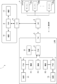
- the device management system 1 to which the present invention is applied has three basic functions of “opening / closing”, “flexibility”, and “measuring” in On-Demand Manufacturing, as shown in FIG. This is realized in three layers: a manager 6, a field manager (FM) 4, and a flexible system manager (FSM: adaptive system controller) 2.
- FM field manager
- FSM flexible system manager
- SM6, FM4, and FSM2 perform a series of management operations such as information detection, data analysis, and control in cooperation between layers.
- the SM6 has a function to manage the openability and metricability of information in the entire device management system 1.
- the SM 6 monitors the service level based on the contract with the customer.
- the SM 6 executes various services such as service provision, quality assurance based on contracts with customers, information protection and measurement, and billing.
- the SM 6 can access information stored in the cloud 8.
- the SM 6 processes the information acquired from the cloud 8 into information to be provided to other SM 6 based on the contract with the customer and transmits it.
- the SM 6 manages one or more FMs 4 under its own management, and determines a communication policy including a communication method of wireless communication by the FM 4, a communication frequency, and the like.
- this SM6 collects information necessary for monitoring the service quality by controlling the subordinate FM 4 so that wireless communication can be performed with an appropriate communication policy according to the situation, and monitoring the service quality. Also do.
- FM4 is managed by SM6 described above. Incidentally, this FM4 may be managed by two or more SM6.
- the FM 4 is basically assigned in units of factories on site, and has a function of realizing opening / closing and measuring performance in units of factories managed by the FM4.
- the FM 4 performs operation in the factory managed by itself, formulation of a control schedule, separation between internal information and external information, and the like according to the communication policy determined by the SM 6.
- the FM 4 manages one or more FSMs 2 installed in a factory on site managed by the FM 4 itself.
- FM4 cooperates with SM6, local service policy for FSM2 to perform device control considering service quality, communication such as information collection and sharing, communication frequency and communication path for communication control of devices and power supply, communication parameters, etc.
- the FM 4 instructs the FSM 2 to rewrite the generated local service policy and local communication policy as necessary.
- the FM 4 collects information necessary for generating a local service policy and a local communication policy for each factory, and monitors the operating state of equipment in the factory, communication quality, and the like.
- the FSM 2 is assigned to each one or more devices 15 installed in the factory and manages them.
- the FSM 2 controls the device 15 based on the local service policy instructed by the FM 4.
- the FSM 2 determines a communication method for controlling the device 15 and the like based on the local communication policy instructed by the FM 4.
- the FMS 2 collects information necessary for generating a local service policy and a local communication policy for each device 15, and executes various controls based on the collected information for the device 15.
- the equipment 15 is a concept including manufacturing equipment installed on a production line, inspection equipment for inspecting the manufacturing equipment, an automated guided vehicle traveling in the factory, and any other equipment used in the factory.
- the device 15 is managed by the FSM 2 and managed through wireless communication with the FSM 2.
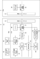
- FIG. 2 shows a block configuration of FSM2.
- the FSM 2 is roughly classified into a system control manager (SCM) 20a and a terminal communication manager (TCM) 20b.
- the FSM 2 includes a system controller 21 and a system measurement unit 22 connected to the SCM 20a, a normal measurement unit 23 and an event measurement unit 24 connected to the system measurement unit 22, and a TCM 20b, respectively.
- a local communication controller 25 and a communication measurement unit 26 are provided.
- a communication interface 27 is further connected to the TCM 20b.
- the SCM 20a is centered on a local service quality manager 28, to which a system control unit 29, a detection information control unit 30, and an information processing unit 32 are connected.
- a buffer 31 is further connected to the detection information control unit 30.
- the TCM 20b is centered on a network access unit 34, to which a terminal communication determination unit 35, a local communication manager 36, a terminal measurement manager 37, and a first data propagation adjustment unit 38 are connected.
- a buffer 39 is further connected to the first data propagation adjusting unit 38.
- the system controller 21 is a wireless communication interface for performing wireless communication with the device 15.
- the system controller 21 transmits a control signal for controlling the device 15 to the device 15 by wireless communication under the control of the system control unit 29, and the device 15 performs various controls based on the control signal.
- the types of control signals transmitted from the system controller 21 include opening / closing control of a physical switch for supplying power to the device 15, all operation control of the device 15, stop of travel of the device 15 in an emergency, and stop of operation Etc.
- the normal measurement unit 23 is a device for detecting various information from the device 15 by wireless communication under the control of the system measurement unit 22.
- the normal measurement unit 23 periodically detects various types of information from the device 15 at normal times when no event occurs.
- the types of information to be detected include, for example, information on the state of the device 15, such as torque value and torque waveform, image information of the device 15, noise of the motor constituting the device 15, vibration frequency and power consumption of the device 15. And other information generated from the device 15 such as the signal strength and delay time of the radio signal transmitted from the device 15.
- the normal measurement unit 23 outputs the detected information to the system measurement unit 22.
- the event measurement unit 24 is a device for detecting various types of information from the device 15 through wireless communication under the control of the system measurement unit 22, similarly to the normal measurement unit 23. However, the event measurement unit 24 measures various information from the device 15 only when an event different from the normal time occurs, for example, when an abnormality is detected in the device 15 or when the device 15 is stopped.
- the information of the measurement object by the event measurement unit 24 is the same as that of the normal measurement unit 23, but the measurement condition may be different from that of the normal measurement unit 23. For example, when an abnormality occurs in the device 15, the frequency of the motor, which is normally detected by the normal measurement unit 23 at intervals of 10 minutes, is measured by the event measurement unit 24 at intervals of 1 minute. Different modes may be used.
- the system measurement unit 22 controls the normal measurement unit 23 and the event measurement unit 24 connected to each other based on an instruction from the SCM 20a.
- the system measurement unit 22 collects information on the measurement target by the normal measurement unit 23 and the event measurement unit 24, and provides the information to the information processing unit 32 in the SCM 20a.
- the system measurement unit 22 monitors the malfunction of the device 15 and the occurrence of various events through the collection of such information, and notifies the SCM 20a of the results.
- the local service quality manager 28 in the SCM 20 a issues an instruction to control the system control unit 29 and the information processing unit 32 based on the local service policy notified from the FM 4.
- the local service quality manager 28 acquires various types of information notified from the system control unit 29 and the information processing unit 32, notifies the local communication manager 36 of the TCM 20b of this information, or performs system control based on the acquired information.
- the unit 29 and the information processing unit 32 are controlled.
- the system control unit 29 controls the system controller 21 based on an instruction from the local service quality manager 28.
- the system control unit 29 determines how to actually control the device 15 in order to realize the local service policy notified from the local service quality manager 28 and notifies the system controller 21 of the specific control policy. To do. Thereby, specific control of the device 15 by the system controller 21 can be executed.
- the information processing unit 32 receives all information collected by the system measurement unit 22.
- the information processing unit 32 transmits the received information to the detection information control unit 30.
- the information processing unit 32 may temporarily store all or part of the information transmitted from the system measurement unit 22 as necessary.
- the information processing unit 32 also transmits information measurement policies by the normal measurement unit 23 and the event measurement unit 24 to the system measurement unit 22 based on an instruction from the local service quality manager 28. Further, the information processing unit 32 is also directly connected to the system control unit 29, and can control the system measurement unit 22 to perform various measurements in conjunction with the control of the device 15 by the system controller 21. It becomes.
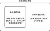
- the detection information control unit 30 determines whether the information detected by the device 15 transmitted via the information processing unit 32 is information intended to be acquired in advance. As shown in FIG. 3, the information detected by the device 15 includes information intended to be acquired (hereinafter referred to as acquisition intention information) and information not intended to be acquired (hereinafter referred to as non-acquisition intention information). It can be roughly divided into two types.
- the acquisition intention information is information that the customer who manages the factory wants to acquire, such as motor noise and device frequency, and is usually defined in advance based on the intention of the customer.
- the non-acquisition intention information is all information other than the acquisition intention information.
- the detected information control unit 30 determines that the detected information is non-acquisition intention information, the detected information is not transmitted to the local service quality manager 28. Control to protect against leakage.
- the detection information control unit 30 may temporarily store the acquisition intention information to be transmitted to the local service quality manager 28 in the buffer 31. This makes it possible to control the timing at which information is sent to the detection information control unit 30 and the timing at which the acquisition intention information is sent to the local service quality manager 28.
- the local communication controller 25 performs communication by controlling the communication device of the device 15 based on the instruction of the TCM 20b.
- the communication measurement unit 26 collects communication control information necessary for communication control and provides it to the terminal measurement manager 37 of the TCM 20b. The policy of collecting communication control information by the communication measuring unit 26 is notified from the terminal measurement manager 37.
- the TCM 20b controls communication between the FSM 2 and the outside based on the local communication policy provided from the FM 4.
- the terminal measurement manager 37 in the TCM 20 b transmits the communication control information transmitted from the communication measurement unit 26 to the local communication manager 36 and the network access unit 34.
- the terminal measurement manager 37 controls collection of communication control information in the communication measurement unit 26 under the control of the local communication manager 36 and the network access unit 34.
- the local communication manager 36 in the TCM 20b notifies the terminal communication determination unit 35 of various communication conditions and policies in accordance with the local communication policy.
- the local communication manager 36 may control the terminal communication determination unit 35 based on the communication control information notified from the terminal measurement manager 37 as necessary.
- the local communication manager 36 transmits the acquisition intention information transmitted from the detection information control unit 30 in the SCM 20 a via the local service quality manager 28 to the network access unit 34.
- the terminal communication determination unit 35 controls communication by the local communication controller 25 based on control by the local communication manager 36 and the network access unit 34.
- the network access unit 34 controls communication between the actual FSM 2 and the outside together with the local communication manager 36.
- the network access unit 34 selects a network that actually transmits data.
- the network access unit 34 transmits the acquisition intention information transmitted from the local communication manager 36 to the first data propagation adjustment unit 38.
- the first data propagation adjustment unit 38 is a device for adjusting the propagation path when data including the acquisition intention information transmitted from the network access unit 34 is transmitted from the FSM 2 to the outside.
- the adjustment of the propagation path may be performed in cooperation with the network access unit 34 as necessary.
- the first data propagation adjustment unit 38 cooperates with a data propagation adjustment unit in the FM 4 to be described later, and performs control so as to propagate through an appropriate communication path without leaking outside the data including the acquisition intention information.
- the first data propagation adjustment unit 38 may temporarily store the data to be transmitted in the buffer 39.
- the communication interface 27 includes various devices necessary for the FSM 2 to perform wireless communication with other FSM 2 and FM 4.
- FIG. 4 shows the block configuration of FM4.
- the FM 4 is roughly classified and configured by a system control manager (SCM) 40a.
- the FM 4 includes a communication interface 41, a local communication policy controller 42, a field communication controller 43, and a field measurement controller 46 connected to the SCM 40 a, and a normal connection connected to the field measurement controller 46.
- a measurement unit 44 and an event measurement unit 45 are provided.
- the SCM 40a is centered on a global communication manager 52, to which a network access unit 49, a field communication policy determination unit 50, a local communication policy determination unit 51, and an information processing unit 53 are connected. Further, a second data propagation adjustment unit 47 is further connected to the network access unit 49, and a buffer 48 is connected to the second data propagation adjustment unit 47.
- the communication interface 41 includes various devices necessary for the FM 4 to perform wireless communication with other FM 4, FSM 2, and SM 4.
- the local communication policy controller 42 provides the local communication policy to the FSM 2 and instructs rewriting thereof.
- the local communication policy controller 42 also collects and shares information detected by the FSM 2 and controls the communication frequency and communication path for controlling the device 15 and the power source.
- the local communication policy controller 42 executes various operations in order to realize the local communication policy provided by the local communication policy determination unit 51.
- the field communication controller 43 controls a communication method and communication frequency related to communication with the FSM2 and SM4.
- the field communication controller 43 executes various operations under the management of the field communication policy determination unit 50.
- the normal measurement unit 44 is a device for detecting various information by wireless communication under the control of the field measurement controller 46.
- the above-described normal measurement unit 23 detects information in units of equipment 15, whereas the normal measurement unit 44 detects various types of information in units of factories.
- the normal measuring unit 44 periodically detects various types of information from the equipment factory during normal times when no event occurs.
- the normal measurement unit 44 detects the operation status of the entire factory as the information to be detected.
- the normal measurement unit 44 measures the rotation state of the motor in the factory at regular intervals, or detects the temperature in the factory.
- the humidity or the like is measured every predetermined time, or the consumption status of each consumable in the factory is measured every predetermined time.
- the normal measurement unit 44 outputs the detected information to the field measurement controller 46.
- the event measurement unit 45 is a device for detecting various types of information from the factory through wireless communication under the control of the field measurement controller 46, similarly to the normal measurement unit 44. However, the event measuring unit 45 measures various information only when some event different from the normal time occurs, for example, when some abnormality is detected in the factory or when it stops. Information on the measurement object by the event measurement unit 45 is the same as that of the normal measurement unit 44.
- the field measurement controller 46 controls the normal measurement unit 44 and the event measurement unit 45 connected to each other based on an instruction from the SCM 40a.
- the field measurement controller 46 collects information on the measurement target by the normal measurement unit 44 and the event measurement unit 45 and provides it to the information processing unit 53 in the SCM 40a.
- the field measurement controller 46 monitors the situation of the entire factory and the occurrence of various events through the collection of such information, and notifies the SCM 40a of the results.
- the second data propagation adjustment unit 47 receives various data via the communication interface 41 and transmits it to the network access unit 49 as necessary, and transmits the data transmitted from the network access unit 49 to the communication interface. It transmits to the outside via 41.
- the second data propagation adjustment unit 47 is a device for adjusting the propagation path when data including the acquisition intention information is transmitted from the FSM 2 and transmitted to the outside.
- the second data propagation adjustment unit 47 cooperates with the first data propagation adjustment unit 38 in the FSM 2 so that the data including the acquisition intention information is propagated through an appropriate communication path without leaking outside. Control.
- the second data propagation adjustment unit 47 may temporarily store the data including the acquisition intention information to be transmitted in the buffer 48.
- the second data propagation adjustment unit 47 may be connected to the normal measurement unit 44 and the event measurement unit 45 described above. Thereby, it is possible to control to adjust the propagation path of the data including the acquisition intention information based on the information measured from the normal measurement unit 44 and the event measurement unit 45. At this time, the second data propagation adjustment unit 47 may perform these operations in cooperation with the network access unit 49. Further, the measurement method of various information by the normal measurement unit 44 and the event measurement unit 45 may be determined based on the acquisition intention information acquired by the second data propagation adjustment unit 47.
- the network access unit 49 controls communication between the actual FM 4 and the outside together with the global communication manager 52.
- the network access unit 49 selects a network that actually transmits data.
- the global communication manager 52 creates a local communication policy and a local service policy in the subordinate FSM 2 for each FSM 2.
- the global communication manager 52 acquires necessary information for generating the local service policy and the local communication policy from the field measurement controller 46 according to the situation.
- the field measurement controller 46 can monitor the operating state and communication quality of the equipment in the factory, it is possible to generate a local service policy and a local communication policy reflecting the information.
- the global communication manager 52 may reflect the service policy notified from the SM 6 in the local service policy and the local communication policy.
- the global communication manager 52 transmits the created local communication policy to the local communication policy determination unit 51.
- the local communication policy determination unit 51 determines a local communication policy suitable for satisfying the local service policy.
- the local communication policy determined by the local communication policy determination unit 51 is provided to the local communication policy controller 42.
- the field communication policy determination unit 50 determines a communication policy related to communication with the FSM2 and SM4. Further, the field communication policy determination unit 50 notifies the field communication controller 43 of the generated communication policy.
- the information processing unit 53 receives all information collected by the field measurement controller 46.
- the information processing unit 53 transmits the received information to the global communication manager 52 and the like.
- the information processing unit 53 may temporarily store all or part of the information transmitted from the field measurement controller 46 as necessary.
- the information processing unit 53 also transmits information measurement policies of the normal measurement unit 44 and the event measurement unit 45 to the field measurement controller 46 based on an instruction from the global communication manager 52. Further, the information processing unit 53 may be directly connected to the local communication policy determining unit 51, and the collected information may be reflected in the determination of the local communication policy by the local communication policy determining unit 51.
- FIG. 5 shows a block configuration of FM4 and SM6 that communicates wirelessly therewith.
- the SM 6 is roughly classified into a cloud service manager (CSM) 60a.
- the SM 6 includes a communication interface 61, a service policy controller 62, a communication controller 63, and a service quality measurement controller 66 that are respectively connected to the CSM 60a.
- the CSM 60a is centered on a global service quality manager 72, to which a service policy determination unit 74, a communication manager 70, and an information processing unit 73 are connected.
- a communication network determination unit 71 and a network access unit 69 are connected to the communication manager 70.
- a third data propagation adjustment unit 67 is further connected to the network access unit 69, and a buffer 68 is connected to the third data propagation adjustment unit 67.
- the communication interface 61 is composed of various devices necessary for the SM 6 to perform wireless communication with the FM 4.
- the service policy controller 62 provides a service policy to the FSM 2 and instructs rewriting thereof.
- the service policy controller 62 executes various operations in order to realize the service policy provided by the service policy determination unit 74.
- the communication controller 63 sets a communication method according to an instruction from the FM 4 and performs communication.
- the communication controller 63 executes various operations under the management of the communication network determination unit 71.
- the service quality measurement controller 66 measures the state of service quality provided by the device management system 1 and provides it to the CSM 60a.
- the service quality measurement controller 66 detects various types of information using the entire system as one unit.
- Information detected by the service quality measurement controller 66 includes an error rate, a loss rate, a received signal strength, a received signal delay amount, a data transmission / reception interval, and the like of data transmitted and received on a service providing line.
- the service quality measurement controller 66 outputs the detected information to the information processing unit 73.
- the third data propagation adjustment unit 67 receives various types of data via the communication interface 61 and transmits the data to the network access unit 69 as necessary, and transmits the data transmitted from the network access unit 69 to the communication interface. Send to the outside via 61.
- the third data propagation adjustment unit 67 is a device for adjusting the propagation path when data including the acquisition intention information is transmitted from the SM 6.
- the third data propagation adjustment unit 67 cooperates with the second data propagation adjustment unit 47 in the FM 4 to control the propagation so that the third data propagation adjustment unit 67 propagates through an appropriate communication path without leaking outside the data including the acquisition intention information. To do.
- the third data propagation adjustment unit 67 may be executed in cooperation with the network access unit 69 in performing these operations. Of course, the third data propagation adjustment unit 67 may temporarily store the data including the acquisition intention information to be transmitted in the buffer 68.
- the network access unit 69 controls communication between the actual SM 6 and the outside together with the communication manager 70.
- the network access unit 69 selects a network that actually transmits data.
- the communication manager 70 monitors the communication status in the subordinate FM 4.
- the communication manager determines a service policy (including communication means and communication frequency) of the entire system.
- the communication network determination unit 71 determines a communication route and a communication method on the route.
- the information processing unit 73 receives information on the status of service quality collected by the service quality measurement controller 66.
- the information processing unit 73 transmits the received information to the global service quality manager 72.
- the information processing unit 73 may temporarily store all or part of the information transmitted from the service quality measurement controller 66 as necessary. Based on an instruction from the global service quality manager 72, the information processing unit 73 can change the measurement policy of information related to service quality to the service quality measurement controller 66 as needed.
- the global service quality manager 72 instructs the service policy determination unit 74 to create an optimum service policy based on the state of the subordinate FM 4. At this time, the creation of a service policy may be instructed based on information on the state of service quality sent via the information processing unit 73. Further, the global service quality manager 72 may instruct creation of a service policy based on acquisition intention information transmitted via the third data propagation adjustment unit 67 and the network access unit 69. The global service quality manager 72 transmits the service policy created in the service policy determination unit 74 to the FM 4 via the communication manager 70, the network access unit 69, and the third data propagation adjustment unit 67.
- the service policy determination unit 74 creates an optimal service policy based on an instruction from the global service quality manager 72.
- the service policy determination unit 74 notifies the global service quality manager 72 of the created service policy.
- FIG. 6 shows a block configuration of the SM 6 and the cloud 8 that communicates wirelessly therewith.
- SM6 the same components and members are denoted by the same reference numerals, and the following description is omitted.
- Each server 80a, 80b,..., 80n in the cloud 8 stores ERP (Enterprise Resource Planning), production management, manufacturing equipment control, power supply information, weather information, and the like.
- ERP Enterprise Resource Planning
- production management production management
- manufacturing equipment control power supply information
- weather information weather information, and the like.
- the SM 6 accesses the cloud 8
- the SM 6 is performed via the network access unit 69.
- the global service quality manager 72 in SM6 includes a service quality evaluation unit 101, a manufacturing process monitoring unit 102, a risk evaluation unit 103, a financial evaluation unit 104, and a data access control unit 105 connected thereto. Yes.
- the service quality evaluation unit 101 acquires information on the state of service quality sent via the information processing unit 73 and evaluates it. Specifically, this service quality evaluation unit 101 actually provides error rate, loss rate, received signal strength, arrival delay amount, distribution of data transmission / reception intervals, etc. Evaluate whether the service level is met.
- the manufacturing process monitoring unit 102 grasps the manufacturing status actually performed in the factory by analyzing various data.
- the risk evaluation unit 103 analyzes and predicts the magnitude of the risk at the manufacturing site, its frequency, etc. by analyzing various data.
- the financial evaluation unit 104 evaluates the financial state in the factory by analyzing various data.
- the data access control unit 105 performs any service in the cloud 8 in order to obtain appropriate information for the service quality evaluation unit 101, the manufacturing process monitoring unit 102, the risk evaluation unit 103, and the financial evaluation unit 104 to perform various evaluations. It is determined whether to access the servers 80a, 80b,. After determining the policy, the data access control unit 105 accesses the cloud 8 via the network access unit 69 and acquires necessary information.
- the SM 6 creates a service policy in the above-described service policy determination unit 74 to execute various services such as quality assurance, information protection and measurement, and billing based on a contract with a customer.
- the service policy determination unit 74 notifies the created service policy to the FM 4 via the service policy controller 62.
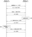
- FIG. 7 shows an outline of a communication sequence between these SM6, FM4, and FSM2.
- the SM 6 transmits a query to the selected FM 4 (step S11). This query requests that the created service policy be determined based on the current state.
- the FM 4 determines that the local service policy can be executed based on the current situation, the FM 4 transmits a response to accept the query to the SM 6 (step S12).
- the FM 4 determines that the service policy cannot be executed based on the current situation, the FM 4 does not transmit any response to the SM 6.
- the SM6 When the SM6 receives the response in step S12, the SM6 transmits information related to various control schedules, necessary communication resources, and the like to the FM4 (step S13).
- the FM 4 refers to the information notified in step S13 and the service policy notified from the SM 6 as necessary, and creates a local communication policy and local service policy in the subordinate FSM 2 for each FSM 2 by the global communication manager 52. To do.
- the global communication manager 52 may acquire necessary information for generating the local service policy and the local communication policy from the operation information such as the factory detected by the field measurement controller 46 as necessary. .
- the FM 4 may refer to all data transmitted from the FSM 2 when creating the local service policy and the local communication policy.
- FM4 transmits the newly created local communication policy and local service policy to FSM2 (step S14).
- the FSM 2 transmits an ACK as a response to the FM 4 when the rewriting to the received local communication policy and local service policy is completed (step S15).
- the FM4 receives such an ACK
- the FM4 transmits an ACK indicating the completion of response to the SM6 (step S16).
- the FSM 2 controls the devices 15 managed by each based on the rewritten new local communication policy and local service policy.
- the FSM 2 controls communication based on the local communication policy via the TCM 20b, and controls services based on the local service policy via the SCM 20a.
- Table 1 shows an example of a local communication policy created by SM6.
- the maximum number of packet transmissions, allowable packet loss (%), minimum allowable received signal strength (dBm), and reception possibility (%, dBm) are defined for each service type.
- the maximum number of packet transmissions is limited to one time.
- the allowable packet loss is 10% or less, 90% or more packets can be received at -65 dBm or more. It will be a requirement to be.
- the maximum number of packet transmissions is 2, and the allowable packet loss may be 20% or less, while the minimum allowable received signal strength is required to be ⁇ 85 dBm.
- FM4 creates candidates for setting the communication conditions between the device 15 and the FSM 2 based on the example of the local communication policy in Table 1 and the communication control information measured by the communication measuring unit 26, for example.
- the FM 4 finally sets specific communication conditions as shown in Table 2, and realizes communication with the device 15 based on this.
- a series of management such as information detection, data analysis, control and the like is cooperated by three layers of SM6, FM4, and FSM2 through such local communication policy and local service policy.
- SM6, FM4, and FSM2 Through such local communication policy and local service policy.
- SM2 will also manage FM4 and FSM2 by including this in the service policy.
- the acquisition intention information is set under the control of the global service quality manager in SM6, and the set acquisition intention information can be notified to FM4 and FSM2 by being included in the service policy.
- the local service quality manager 28 instructs the detection information control unit 30 to determine the acquisition intention information.
- the detection information control unit 30 determines whether the information detected by the device 15 is acquisition intention information or non-acquisition intention information.
- the detection information control unit 30 determines that the detected information is acquisition intention information, it means that the information requested from the customer side has been detected. That is, the fact that the detected information control unit 30 has determined that the detected information is acquisition intention information means that it has been confirmed that the customer has not acquired information that is not desired to be acquired. In such a case, the detection information control unit 30 transmits this acquisition intention information to the local service quality manager 28, and the local service quality manager 28 transmits this to the TCM 20b.
- the detected information control unit 30 determines that the detected information is non-acquisition intention information, it means that information other than the information requested from the customer side has been detected. In other words, it means that the customer has acquired information that the customer does not want to acquire. Since acquisition of such non-acquisition intention information may lead to a breach of contract with a customer, it can be said that the operation side of the device management system 1 wants to avoid as much as possible. In such a case, the detection information control unit 30 does not transmit the non-acquisition intention information to the local service quality manager 28. As a result, it is possible to prevent the detected non-acquisition intention information from leaking to the outside, but the detection information detection information control unit 30 on the system side deletes the non-acquisition intention information as it is. May be.
- the detection information control unit 30 By performing the control by the detection information control unit 30 as described above, it is possible to prevent the non-acquisition intention information that is not originally detected from being transferred to the outside, and to transfer only the acquisition intention information originally desired to be detected to the outside. Is possible.
- the detection information control unit 30 By executing the above-described control by the detection information control unit 30, it is guaranteed that only the acquisition intention information is acquired.
- the operation by the detection information control unit 30 is not limited to the above, and can be realized by any method as long as control is performed so as to ensure that only acquisition intention information is acquired. There may be.
- the data including the detected acquisition intention information is sent to the first data propagation adjustment unit 38 via the local service quality manager 28, the local communication manager 36, and the network access unit 34.
- the first data propagation adjustment unit 38 adjusts the propagation path when transmitting data including the acquisition intention information from the FSM 2 to the outside. This adjustment of the propagation path proceeds in cooperation with the second data propagation adjustment unit 47 in FM4 and further with the third data propagation adjustment unit 67 in SM6.
- the route extending in the horizontal direction with respect to SM6 shown in FIG. 1 is a route that can be accessed only by the company or its affiliated company, the propagation path of the data including the acquisition intention information is traced along the horizontal route. Will be controlled.
- FIG. 8 shows a sequence for adjusting the propagation path between the first data propagation adjustment unit 38 and the second data propagation adjustment unit 47.
- an adjustment start query is transmitted from the first data propagation adjustment unit 38 side that transmits data (step S21).
- the second data propagation adjusting unit 47 that has received the adjustment start query returns a query response to the first data propagation adjusting unit 38 when the adjustment start can be realized in response to this.
- the first data propagation adjustment unit 38 transmits the candidate route information to the second data propagation adjustment unit 47 (step S23).
- This candidate route information describes one or more propagation path candidates for transmitting data.
- the second data propagation adjustment unit 47 that has received the candidate route information transmits ACK to the first data propagation adjustment unit 38 (step S24).
- the second data propagation adjustment unit 47 selects one propagation path from among the propagation paths included in the candidate route information in step S25.
- the second data propagation coordinating unit 47 selects this propagation route based on whether or not the route can be accessed only by its own company or its affiliated company.
- the second data propagation adjustment unit 47 transmits the assignment of route information in which the propagation path selected by itself is described to the first data propagation adjustment unit 38 (step S26).
- the first data propagation adjustment unit 38 receives the assignment of the route information
- the first data propagation adjustment unit 38 transmits ACK to the second data propagation adjustment unit 47 (step S27).
- step S28 the process proceeds to step S28, and the first data propagation adjustment unit 38 establishes a wireless communication link between the FSM 2 and the FM 4 for the propagation path assigned in step S26.
- step S ⁇ b> 29 the first data propagation adjustment unit 38 transmits information related to the propagation path in which the wireless communication link is established to the second data propagation adjustment unit 47.
- the second data propagation adjustment unit 47 receives this, it transmits ACK to the first data propagation adjustment unit 38.
- the detection information control unit 30 has determined that the non-acquisition intention information is the acquisition position information
- the first data propagation adjustment unit 38 and the second data propagation adjustment unit 47 Since the third data propagation adjusting unit 67 adjusts the propagation path of the data including the information, it can be prevented from leaking to the outside.
- the leakage of the non-acquisition intention information to the outside is added to the detection information control unit 30, and the first data propagation adjustment unit 38, the second data propagation adjustment unit 47, and the third The data propagation adjustment unit 67 can prevent it in two stages.
- the acquisition position information is included in the data to be transmitted. It is necessary to determine whether or not In such a case, the first data propagation adjustment unit 38, the second data propagation adjustment unit 47, and the third data propagation adjustment unit 67 analyze the data itself or tagging of the information, and determine the information to be transmitted. The category will be specified. Then, according to the service policy for each identified category and the communication system selection policy depending on the radio wave environment, it is determined which communication device (FSM2, FM4, SM6) is used and how to perform transmission. It will be.
- FSM2, FM4, SM6 communication device
- various types of information measured from the device 15 by the normal measurement unit 23 and the event measurement unit 24 are statistically analyzed, and the analysis results are obtained from the above-described device 15. You may make it reflect in the setting of control or communication conditions.
- the measured information is sent to the communication interface 27 through the information processing unit 32, the local service quality manager 28, the network access unit 34, the first data propagation adjustment unit 38, and the like.
- the communication interface 27 transmits the transmitted information to the communication interface 41 in the FM 4 by wireless communication.
- the information is sent to the global communication manager 52 via the second data propagation adjustment unit 47 and the network access unit 49.
- the global communication manager 52 performs a statistical analysis on the transmitted information.
- the transmitted information is the intensity of the signal received from the device 15
- the sensitivity (dBm) distribution may be statistically analyzed as shown in FIG.
- the global communication manager 52 makes various determinations based on the statistical distribution.
- the type of this determination for example, the ratio of the sensitivity exceeding the predetermined value shown in FIG.
- the global communication manager 52 determines what control is performed on the device 15 or under what communication conditions according to the result of this determination.
- This control policy is included in the above-described local service policy and local communication policy and transmitted to the FSM 2.
- This transmission route is in the opposite direction to the route through which the above information is sent.
- the FSM 2 controls the device 15 or sets communication conditions based on the local service policy and local communication policy reflecting the control policy. Thereby, the statistical analysis result based on the information detected from the device 15 can be reflected in the control of the device 15 and the setting of the communication condition.
- this statistical analysis and determination, and further determination of a new control policy and communication conditions may be completed in the FSM2.
- the local service quality manager 28 plays a central role in executing them.
- the ratio of the packet to the delay time may be statistically analyzed.
- the horizontal axis indicates the packet delay time
- the vertical axis indicates the ratio.
- the packet delayed by 0.4 ms is 98%
- the packet delayed by 4 ms is 98%.
- a threshold may be set in advance for the ratio to the delay amount, and the control policy and communication conditions of the device 15 may be adjusted depending on whether or not the threshold is exceeded.
- fluctuations in the reception time interval may be targeted.
- These long-time averages, maximum and minimum values, standard deviation, variance, etc. Analysis may be performed based on any of the above items. Any object may be used as long as it is based on information detected from the analysis target device 15.
- the device 15 installed in the factory By making good use of the control function of the device 15 in accordance with the statistical analysis result, the device 15 installed in the factory, and thus the work process in the entire factory is proposed, and based on the proposed improvement measures. It is also possible to newly manage the device 15. For example, statistically analyze the impact of control changes in the device 15 and malfunctions of the device 15 on productivity, and based on this, the customer is encouraged to stop the device 15 or replace consumables. It is also possible to connect to.
Landscapes
- Engineering & Computer Science (AREA)
- Physics & Mathematics (AREA)
- General Physics & Mathematics (AREA)
- Automation & Control Theory (AREA)
- Quality & Reliability (AREA)
- Manufacturing & Machinery (AREA)
- General Engineering & Computer Science (AREA)
- Business, Economics & Management (AREA)
- Health & Medical Sciences (AREA)
- Signal Processing (AREA)
- Computer Networks & Wireless Communication (AREA)
- Strategic Management (AREA)
- Theoretical Computer Science (AREA)
- General Health & Medical Sciences (AREA)
- Human Resources & Organizations (AREA)
- Marketing (AREA)
- Primary Health Care (AREA)
- Economics (AREA)
- Tourism & Hospitality (AREA)
- General Business, Economics & Management (AREA)
- Software Systems (AREA)
- Computer Vision & Pattern Recognition (AREA)
- Artificial Intelligence (AREA)
- Evolutionary Computation (AREA)
- Medical Informatics (AREA)
- Testing And Monitoring For Control Systems (AREA)
- General Factory Administration (AREA)
- Mobile Radio Communication Systems (AREA)
- Management, Administration, Business Operations System, And Electronic Commerce (AREA)
Abstract
L'invention comprend une FSM (2) qui est attribuée à au moins un dispositif (15) installé dans une usine et qui surveille et commande sans fil le dispositif ou les dispositifs. La FSM (2) comprend : une unité de mesure de système (22) destinée à détecter des informations provenant du dispositif (15) ; une unité de commande d'informations de détection (30) destinée à commander seulement les informations prévues pour l'acquisition, qui sont prévues pour être acquises, parmi les informations détectées par l'unité de mesure de système (22) afin de garantir que les informations prévues pour l'acquisition sont acquises par la FSM (2) ; une première unité de réglage de propagation des données (38) qui, lorsque des données contenant les informations après avoir été soumises à la commande par l'unité de commande d'informations de détection (30) sont émises vers l'extérieur, ajuste le trajet de propagation des données ; et un gestionnaire de qualité de service local (28) ainsi qu'un gestionnaire de communication local (36) destinés à commander le dispositif (15) en se basant sur les informations détectées par la première unité de réglage de propagation de données (38) ou une politique de commande provenant de l'extérieur.
Priority Applications (3)
| Application Number | Priority Date | Filing Date | Title |
|---|---|---|---|
| CN201780007045.3A CN108475054B (zh) | 2016-01-20 | 2017-01-17 | 设备管理系统 |
| EP17741369.7A EP3407149B1 (fr) | 2016-01-20 | 2017-01-17 | Système de gestion de dispositif |
| US16/070,975 US11119452B2 (en) | 2016-01-20 | 2017-01-17 | Equipment management system |
Applications Claiming Priority (2)
| Application Number | Priority Date | Filing Date | Title |
|---|---|---|---|
| JP2016008722A JP6779451B2 (ja) | 2016-01-20 | 2016-01-20 | 機器管理システム |
| JP2016-008722 | 2016-01-20 |
Publications (1)
| Publication Number | Publication Date |
|---|---|
| WO2017126491A1 true WO2017126491A1 (fr) | 2017-07-27 |
Family
ID=59362233
Family Applications (1)
| Application Number | Title | Priority Date | Filing Date |
|---|---|---|---|
| PCT/JP2017/001341 Ceased WO2017126491A1 (fr) | 2016-01-20 | 2017-01-17 | Système de gestion de dispositif |
Country Status (5)
| Country | Link |
|---|---|
| US (1) | US11119452B2 (fr) |
| EP (1) | EP3407149B1 (fr) |
| JP (1) | JP6779451B2 (fr) |
| CN (1) | CN108475054B (fr) |
| WO (1) | WO2017126491A1 (fr) |
Cited By (1)
| Publication number | Priority date | Publication date | Assignee | Title |
|---|---|---|---|---|
| JP2019176390A (ja) * | 2018-03-29 | 2019-10-10 | 国立研究開発法人情報通信研究機構 | 通信ネットワークシステム及び通信ネットワーク方法 |
Families Citing this family (1)
| Publication number | Priority date | Publication date | Assignee | Title |
|---|---|---|---|---|
| WO2022033692A1 (fr) * | 2020-08-13 | 2022-02-17 | Vega Grieshaber Kg | Dispositif de mesure à activation ajustable |
Citations (3)
| Publication number | Priority date | Publication date | Assignee | Title |
|---|---|---|---|---|
| JP2000039901A (ja) * | 1998-07-22 | 2000-02-08 | Toshiba Corp | リモート監視・調整装置 |
| JP2000207019A (ja) * | 1999-01-18 | 2000-07-28 | Toshiba Corp | プラント監視装置 |
| WO2015159555A1 (fr) * | 2014-04-18 | 2015-10-22 | 国立研究開発法人情報通信研究機構 | Système de gestion de ressources |
Family Cites Families (5)
| Publication number | Priority date | Publication date | Assignee | Title |
|---|---|---|---|---|
| US9015059B2 (en) * | 2005-09-19 | 2015-04-21 | Omnitracs, Llc | Wireless system for automatic ordering of maintenance parts for equipment |
| JP2012178110A (ja) * | 2011-02-28 | 2012-09-13 | Seiko Epson Corp | 文書情報記録装置、文書情報記録方法、文書情報記録プログラムおよび文書情報記録システム |
| CN102523103B (zh) * | 2011-11-10 | 2014-07-02 | 浙江工业大学 | 一种工业监控网络数据采集结点 |
| US10244000B2 (en) * | 2014-02-24 | 2019-03-26 | Honeywell International Inc. | Apparatus and method for establishing seamless secure communications between components in an industrial control and automation system |
| CN104267711B (zh) * | 2014-11-03 | 2017-01-11 | 四川烟草工业有限责任公司 | 烟草物流系统运行状态监测及故障诊断方法 |
-
2016
- 2016-01-20 JP JP2016008722A patent/JP6779451B2/ja active Active
-
2017
- 2017-01-17 EP EP17741369.7A patent/EP3407149B1/fr active Active
- 2017-01-17 WO PCT/JP2017/001341 patent/WO2017126491A1/fr not_active Ceased
- 2017-01-17 CN CN201780007045.3A patent/CN108475054B/zh active Active
- 2017-01-17 US US16/070,975 patent/US11119452B2/en active Active
Patent Citations (3)
| Publication number | Priority date | Publication date | Assignee | Title |
|---|---|---|---|---|
| JP2000039901A (ja) * | 1998-07-22 | 2000-02-08 | Toshiba Corp | リモート監視・調整装置 |
| JP2000207019A (ja) * | 1999-01-18 | 2000-07-28 | Toshiba Corp | プラント監視装置 |
| WO2015159555A1 (fr) * | 2014-04-18 | 2015-10-22 | 国立研究開発法人情報通信研究機構 | Système de gestion de ressources |
Non-Patent Citations (1)
| Title |
|---|
| See also references of EP3407149A4 * |
Cited By (4)
| Publication number | Priority date | Publication date | Assignee | Title |
|---|---|---|---|---|
| JP2019176390A (ja) * | 2018-03-29 | 2019-10-10 | 国立研究開発法人情報通信研究機構 | 通信ネットワークシステム及び通信ネットワーク方法 |
| EP3780697A4 (fr) * | 2018-03-29 | 2021-12-29 | National Institute of Information and Communications Technology | Système de réseau de communication et procédé de réseau de communication |
| JP7284487B2 (ja) | 2018-03-29 | 2023-05-31 | 国立研究開発法人情報通信研究機構 | 通信ネットワークシステム及び通信ネットワーク方法 |
| US11838934B2 (en) | 2018-03-29 | 2023-12-05 | National Institute Of Information And Communications Technology | Communications network system managing communications policies based on detected state of communication environment, and communications network method |
Also Published As
| Publication number | Publication date |
|---|---|
| EP3407149A4 (fr) | 2019-10-30 |
| JP6779451B2 (ja) | 2020-11-04 |
| CN108475054B (zh) | 2021-05-18 |
| JP2017130031A (ja) | 2017-07-27 |
| US20190243315A1 (en) | 2019-08-08 |
| US11119452B2 (en) | 2021-09-14 |
| EP3407149B1 (fr) | 2022-01-12 |
| EP3407149A1 (fr) | 2018-11-28 |
| CN108475054A (zh) | 2018-08-31 |
Similar Documents
| Publication | Publication Date | Title |
|---|---|---|
| US11751067B2 (en) | Performance assurance and optimization for GAA and PAL devices in a CBRS network for private enterprise environment | |
| EP2568383B1 (fr) | Système de surveillance de services en nuage | |
| US9396019B2 (en) | Management communication | |
| US20200126167A1 (en) | Programmable manufacturing advisor for smart production systems | |
| US20180167445A1 (en) | Edge Computing System | |
| WO2014077898A2 (fr) | Système et procédé pour conférer de l'intelligence opérationnelle à des dispositifs gérés | |
| US11184794B2 (en) | Systems and methods for distribution of application logic in digital networks | |
| US11212173B2 (en) | Model-driven technique for virtual network function rehoming for service chains | |
| US12380013B2 (en) | Method and apparatus for determining collection frequency of a monitoring device | |
| US10547384B2 (en) | Multi-layer system optimization | |
| Arouk et al. | Cost optimization of cloud-RAN planning and provisioning for 5G networks | |
| CN107292598A (zh) | 一种支付路由方法及支付路由中间件 | |
| US20200314204A1 (en) | Method for operating a network-aware container orchestration system | |
| US10187273B2 (en) | Monitoring wireless station experience on a wi-fi network by emulating client radios | |
| JP6779451B2 (ja) | 機器管理システム | |
| CN111245938B (zh) | 机器人集群管理方法、机器人集群、机器人以及相关设备 | |
| US20160050151A1 (en) | Method and apparatus for ripple rate sensitive and bottleneck aware resource adaptation for real-time streaming workflows | |
| CN105162633A (zh) | 一种在基于容器的多操作系统中管理网络的方法和装置 | |
| US11924300B2 (en) | Methods for controlling a multi-access edge computing network | |
| CN102801556A (zh) | 网络性能优化方法及装置 | |
| Shah et al. | 5G Non-Public Networks for Industry 4.0: Architecture, Use Cases, and Future Directions | |
| KR20110064685A (ko) | 트래픽 변동성과 망 요소 장애를 대비할 수 있는 보정계수 산출 방법 및 그를 이용한 ip 망의 링크 용량 설계 방법 | |
| AU2006312284A1 (en) | System and method for routing information | |
| Zeyeum | Deep Reinforcement Learning for Dynamic Network Slicing and Resource Orchestration in Software-Defined Critical Telecom Infrastructure | |
| Colledani et al. | Technology based industrial product-services supporting robustness in manufacturing systems |
Legal Events
| Date | Code | Title | Description |
|---|---|---|---|
| 121 | Ep: the epo has been informed by wipo that ep was designated in this application |
Ref document number: 17741369 Country of ref document: EP Kind code of ref document: A1 |
|
| NENP | Non-entry into the national phase |
Ref country code: DE |
|
| WWE | Wipo information: entry into national phase |
Ref document number: 2017741369 Country of ref document: EP |
|
| ENP | Entry into the national phase |
Ref document number: 2017741369 Country of ref document: EP Effective date: 20180820 |