WO2017133617A1 - Dispositif et procédé destinés à un système de communication sans fil, et dispositif de gestion de spectre - Google Patents
Dispositif et procédé destinés à un système de communication sans fil, et dispositif de gestion de spectre Download PDFInfo
- Publication number
- WO2017133617A1 WO2017133617A1 PCT/CN2017/072599 CN2017072599W WO2017133617A1 WO 2017133617 A1 WO2017133617 A1 WO 2017133617A1 CN 2017072599 W CN2017072599 W CN 2017072599W WO 2017133617 A1 WO2017133617 A1 WO 2017133617A1
- Authority
- WO
- WIPO (PCT)
- Prior art keywords
- carrier
- channel
- detection
- carriers
- group
- Prior art date
- Legal status (The legal status is an assumption and is not a legal conclusion. Google has not performed a legal analysis and makes no representation as to the accuracy of the status listed.)
- Ceased
Links
Images




Classifications
-
- H—ELECTRICITY
- H04—ELECTRIC COMMUNICATION TECHNIQUE
- H04W—WIRELESS COMMUNICATION NETWORKS
- H04W74/00—Wireless channel access
- H04W74/08—Non-scheduled access, e.g. ALOHA
- H04W74/0808—Non-scheduled access, e.g. ALOHA using carrier sensing, e.g. carrier sense multiple access [CSMA]
- H04W74/0816—Non-scheduled access, e.g. ALOHA using carrier sensing, e.g. carrier sense multiple access [CSMA] with collision avoidance
-
- H—ELECTRICITY
- H04—ELECTRIC COMMUNICATION TECHNIQUE
- H04W—WIRELESS COMMUNICATION NETWORKS
- H04W16/00—Network planning, e.g. coverage or traffic planning tools; Network deployment, e.g. resource partitioning or cells structures
- H04W16/02—Resource partitioning among network components, e.g. reuse partitioning
- H04W16/10—Dynamic resource partitioning
-
- H—ELECTRICITY
- H04—ELECTRIC COMMUNICATION TECHNIQUE
- H04L—TRANSMISSION OF DIGITAL INFORMATION, e.g. TELEGRAPHIC COMMUNICATION
- H04L5/00—Arrangements affording multiple use of the transmission path
- H04L5/0001—Arrangements for dividing the transmission path
- H04L5/0003—Two-dimensional division
- H04L5/0005—Time-frequency
- H04L5/0007—Time-frequency the frequencies being orthogonal, e.g. OFDM(A) or DMT
- H04L5/001—Time-frequency the frequencies being orthogonal, e.g. OFDM(A) or DMT the frequencies being arranged in component carriers
-
- H—ELECTRICITY
- H04—ELECTRIC COMMUNICATION TECHNIQUE
- H04L—TRANSMISSION OF DIGITAL INFORMATION, e.g. TELEGRAPHIC COMMUNICATION
- H04L5/00—Arrangements affording multiple use of the transmission path
- H04L5/0091—Signalling for the administration of the divided path, e.g. signalling of configuration information
- H04L5/0092—Indication of how the channel is divided
-
- H—ELECTRICITY
- H04—ELECTRIC COMMUNICATION TECHNIQUE
- H04W—WIRELESS COMMUNICATION NETWORKS
- H04W16/00—Network planning, e.g. coverage or traffic planning tools; Network deployment, e.g. resource partitioning or cells structures
- H04W16/02—Resource partitioning among network components, e.g. reuse partitioning
- H04W16/06—Hybrid resource partitioning, e.g. channel borrowing
-
- H—ELECTRICITY
- H04—ELECTRIC COMMUNICATION TECHNIQUE
- H04W—WIRELESS COMMUNICATION NETWORKS
- H04W16/00—Network planning, e.g. coverage or traffic planning tools; Network deployment, e.g. resource partitioning or cells structures
- H04W16/14—Spectrum sharing arrangements between different networks
-
- H—ELECTRICITY
- H04—ELECTRIC COMMUNICATION TECHNIQUE
- H04W—WIRELESS COMMUNICATION NETWORKS
- H04W72/00—Local resource management
- H04W72/04—Wireless resource allocation
- H04W72/044—Wireless resource allocation based on the type of the allocated resource
- H04W72/0453—Resources in frequency domain, e.g. a carrier in FDMA
-
- H—ELECTRICITY
- H04—ELECTRIC COMMUNICATION TECHNIQUE
- H04W—WIRELESS COMMUNICATION NETWORKS
- H04W72/00—Local resource management
- H04W72/12—Wireless traffic scheduling
- H04W72/1263—Mapping of traffic onto schedule, e.g. scheduled allocation or multiplexing of flows
- H04W72/1268—Mapping of traffic onto schedule, e.g. scheduled allocation or multiplexing of flows of uplink data flows
-
- H—ELECTRICITY
- H04—ELECTRIC COMMUNICATION TECHNIQUE
- H04W—WIRELESS COMMUNICATION NETWORKS
- H04W72/00—Local resource management
- H04W72/20—Control channels or signalling for resource management
- H04W72/21—Control channels or signalling for resource management in the uplink direction of a wireless link, i.e. towards the network
-
- H—ELECTRICITY
- H04—ELECTRIC COMMUNICATION TECHNIQUE
- H04W—WIRELESS COMMUNICATION NETWORKS
- H04W72/00—Local resource management
- H04W72/20—Control channels or signalling for resource management
- H04W72/23—Control channels or signalling for resource management in the downlink direction of a wireless link, i.e. towards a terminal
-
- H—ELECTRICITY
- H04—ELECTRIC COMMUNICATION TECHNIQUE
- H04W—WIRELESS COMMUNICATION NETWORKS
- H04W72/00—Local resource management
- H04W72/50—Allocation or scheduling criteria for wireless resources
- H04W72/56—Allocation or scheduling criteria for wireless resources based on priority criteria
-
- H—ELECTRICITY
- H04—ELECTRIC COMMUNICATION TECHNIQUE
- H04W—WIRELESS COMMUNICATION NETWORKS
- H04W74/00—Wireless channel access
- H04W74/002—Transmission of channel access control information
-
- H—ELECTRICITY
- H04—ELECTRIC COMMUNICATION TECHNIQUE
- H04W—WIRELESS COMMUNICATION NETWORKS
- H04W74/00—Wireless channel access
- H04W74/08—Non-scheduled access, e.g. ALOHA
- H04W74/0833—Random access procedures, e.g. with 4-step access
-
- H—ELECTRICITY
- H04—ELECTRIC COMMUNICATION TECHNIQUE
- H04W—WIRELESS COMMUNICATION NETWORKS
- H04W74/00—Wireless channel access
- H04W74/08—Non-scheduled access, e.g. ALOHA
- H04W74/0808—Non-scheduled access, e.g. ALOHA using carrier sensing, e.g. carrier sense multiple access [CSMA]
Definitions
- FIG. 5 is a block diagram showing another structural example of the processing circuit in FIG. 1;
- Figure 12 is an example of the operation of the channel detecting unit
- FIG. 16 shows a flow chart of a method for wireless communication in accordance with one embodiment of the present application
- FIG. 19 shows another example of information flow between a base station and a user equipment
- 22 is a block diagram showing a second example of a schematic configuration of an eNB to which the technology of the present disclosure may be applied;
- 25 is a block diagram of an exemplary structure of a general purpose personal computer in which methods and/or apparatus and/or systems in accordance with embodiments of the present invention may be implemented.
- the carrier grouping unit 1004 may perform grouping according to at least one of: a frequency band position of each carrier, a usage status of each carrier, an amount of data to be transmitted for each type of service of the user equipment, and information in the geographic location database.
- the amount of data to be transmitted for each type of service of the user equipment can be obtained, for example, according to a status buffer report (BSR).
- BSR status buffer report
- the carrier grouping unit 1004 can perform grouping according to information in the BSR uploaded by the user equipment.
- the packet information generating unit 1002 generates carrier group information indicating the packet status of the carrier, for example, information indicating which carriers are included in each group of carriers.
- the carrier grouping information may include information indicating a group in which a certain carrier is located and information on whether the carrier is a primary carrier or a secondary carrier in the group. For example, if a group of carriers includes carrier 1, carrier 2, and carrier 3, and carrier 1 is the primary carrier and carriers 2 and 3 are the secondary carriers, the carrier grouping information may be: carrier 1 - primary carrier; carrier 2 carrier Secondary carrier of carrier 1; secondary carrier of carrier 3 - carrier 1.
- Channel detection can be implemented by LBT (Listen before talk), which checks whether the channel is idle by means of Clear Channel Assessment (CCA) before using the channel or carrier.
- CCA Clear Channel Assessment
- the CCA may determine whether the channel is occupied by using the result of energy detection on the channel.
- each group of channel detection parameters includes at least one of the following: energy detection category, energy detection threshold
- the threshold of the energy detection is used to determine whether the channel is occupied during the energy detection process, for example, when the result of the energy detection indicates that the accumulated energy is higher than the threshold, the channel is considered to be occupied.
- the category of energy detection is used to reflect the specific manner of energy detection.
- the categories of energy detection include: energy detection that does not include random backoff, energy detection that includes random backoff but contention window size (CWS), energy that includes random backoff and variable contention window size. Detection.
- FIG. 3 is a schematic diagram showing the categories of energy detection, and (a), (b), and (c) of FIG. 3 respectively show the above three categories.
- the energy detection indicates that the data is directly after idle. Transmission, wherein in categories (b) and (c), a random backoff and an additional defer are required after the end of the initial detection period, wherein in the random backoff period, energy detection is still performed, during which time A random backoff counter (also referred to simply as a counter) is used to perform backoff.
- the count of the random backoff counter is interrupted, wherein the random backoff counter is set based on the size of the contention window.
- the apparatus 100 may further include: a transceiver unit 102 configured to transmit carrier group information and channel detection parameters to the user equipment and then send an uplink scheduling grant to the user equipment.
- the carrier group information and the channel detection parameter are sent on the licensed frequency band.
- the transceiver unit 102 sends an uplink scheduling grant on the licensed frequency band.
- the transceiver unit 102 correspondingly sends multiple uplink scheduling grants, that is, notifies the user equipment that it can use multiple carriers for uplink data transmission.
- the apparatus 100 improves uplink resource utilization efficiency of an unlicensed frequency band by performing uplink scheduling on a carrier group instead of a single carrier.
- the device 100 enables the user equipment to be unlicensed by simultaneously scheduling uplink transmission resources on multiple carriers for the user equipment.
- the uplink data is transmitted on multiple carriers on the right frequency band, that is, the carrier aggregation on the unlicensed frequency band is implemented.
- the channel detecting unit 1005 does not simultaneously perform channel detection on the first carrier and the second carrier, but performs cascaded channel detection on the first carrier and the second carrier. For example, when the channel detection for the first carrier is not completed, but it can be determined that the channel is occupied, channel detection for the second carrier is started. Exemplarily, the channel detection for the first carrier can still continue at this time.
- a plurality of detecting units 501 can be set to perform channel detection of the first carrier and the second carrier, respectively.
- the channel detection for the second carrier lasts for a shorter time than the channel detection for the first carrier, but both have the same cutoff time (in the present embodiment, the cutoff time is, for example, The time when the downlink time slot arrives).
- FIG. 8 shows a block diagram of an apparatus 200 for wireless communication, the apparatus 200 including at least one processing circuit 201 configured to group carriers based on received non-licensed frequency bands from a base station, in accordance with an embodiment of the present application.
- the processing circuit 201 includes a carrier group determining unit 2001 and a channel detecting unit 2002.
- these functional modules may be implemented by one processing circuit, or may be implemented by one processing circuit, or implemented as part of one processing circuit, or each functional module may be implemented by multiple processing circuits.
- the implementation of the functional modules is non-limiting.
- the processing circuit 201 may be, for example, a central processing unit (CPU) having data processing capabilities, a microprocessor, an integrated circuit module, or the like.
- CPU central processing unit
- the user equipment When the user equipment where the device 200 is located is to use an unlicensed frequency band for data transmission, the user equipment first sends a request to the base station and receives an uplink scheduling grant from the base station, and then uses the uplink transmission resource of the unlicensed frequency band according to the uplink scheduling grant. Since there may be carriers that other user equipments are scheduling using the uplink scheduling grant, the user equipment needs to perform channel detection before transmitting data, and can use the carrier transmission scheduled by the uplink scheduling grant only when the channel detection indicates that the channel is idle. data. Correspondingly, the user equipment also needs to obtain the channel detection parameters configured by the base station.
- the user equipment also obtains carrier group information from the base station.
- the base station divides carriers into multiple groups and generates an uplink scheduling grant for each carrier group. Therefore, the uplink scheduling grant received by the user equipment is valid for the carrier group, even though the uplink scheduling grant may only include an indication for one carrier.
- the carrier group determining unit 2001 determines that the scheduled carrier is the carrier 1 from the uplink scheduling grant, and determines that the carrier grouped in the same group as the carrier 1 includes the carrier 2 and the carrier 3 according to the carrier group information.
- Channel detection unit 2002 performs channel detection of carriers 1-3 using channel detection parameters for the set of carriers received from the base station. As long as any one of the carriers 1-3 is idle, the user equipment can use the idle carrier for data transmission.
- the channel detecting unit 2002 performs cascaded channel detection for each carrier group, respectively, and the user equipment selects a carrier whose channel detection result indicates that the channel is idle at the end of the channel detection period for data transmission.
- channel detection for the second carrier can continue.
- the channel detection for the second carrier lasts for a shorter time than the channel detection for the first carrier, but both have the same cutoff time (in the present embodiment, the cutoff time is, for example, PUSCH subframe start boundary).
- the detecting unit 601 may be configured to determine when the energy value accumulated for the energy detection of the carrier within a predetermined period of time exceeds a threshold value for determining whether the channel is occupied in the energy detection. This carrier is occupied.
- the predetermined period of time can be set, for example, to 9 microseconds or longer.
- the channel detecting unit 2002 may further include: a control unit 603 configured to control the trigger unit 602 to sequentially trigger for all carriers in each group of carriers such that only the previous one
- the channel detection of the carrier indicates that the channel detection of the next carrier is started when the previous carrier is occupied until the physical uplink shared channel PUSCH starts, and all carriers in the carrier group are traversed before the start of the PUSCH.
- the channel detecting unit 2002 reduces the amount of calculation required for channel detection by performing channel detection of all carriers in the carrier group in cascade in a period before the start of the PUSCH.
- the start times of channel detection for each carrier in each group are different, but the cutoff time of channel detection is the same. If the channel detection result indicates that there are multiple carriers idle at the cutoff time, one carrier is selected for data transmission, for example, the primary carrier is selected if the primary carrier is idle, otherwise the secondary carrier is randomly selected or selected according to other predetermined rules.
- the predetermined rule may be determined, for example, according to factors such as channel quality.
- control unit 603 may further determine a primary carrier and a secondary carrier in the carrier group according to the carrier group information, the control unit 603 uses the primary carrier as the first carrier, and the triggering unit 602 indicates that the primary carrier is occupied when the channel detection of the primary carrier is occupied.
- the secondary carriers are triggered in sequence. In other words, the control unit 603 performs control such that channel detection of the primary carrier is performed first, and channel detection of the secondary carrier is performed when the channel detection of the primary carrier indicates that the primary carrier is occupied, wherein the sequence of channel detection of the secondary carrier may be Randomly determined, it can also be determined by the control unit according to, for example, a band position or the like.
- the channel detection of the primary carrier can be more complicated than the channel detection of the secondary carrier, and the channel detection parameters are more strictly set.
- the channel detection is energy detection
- the class of energy detection for the primary carrier may be energy detection including random backoff
- the class of energy detection for the secondary carrier is energy detection that does not include random backoff.
- the energy detection including random backoff includes an initial detection phase, a random backoff phase, and an additional delay phase.
- the energy detection for the primary carrier indicates that the primary carrier is occupied, including one of the following: energy detection in the initial detection phase.
- the indication channel is not idle, the count of the random backoff phase counter is interrupted, and the energy detection during the additional delay phase indicates that the channel is not idle.
- Figure 12 shows a block diagram of a spectrum management apparatus 300, according to one embodiment of the present application, as shown in Figure 12, the spectrum management apparatus 300 includes: at least one processing circuit 301 configured to group carriers on an unlicensed band And a transmitting unit 302 configured to provide carrier group information related to the packet of the carrier to the base station.
- the processing circuit 301 may be, for example, a central processing unit (CPU) having data processing capabilities, a microprocessor, an integrated circuit module, or the like.
- CPU central processing unit
- the processing circuit 301 can perform grouping by selecting a primary carrier and then selecting a secondary carrier assigned to the primary carrier, wherein in one carrier group, the user equipment uses the primary carrier for data transmission with a higher priority than using The priority of the secondary carrier for data transmission.
- the processing circuit 301 can also adopt other specific grouping methods, for example, first selecting carriers to be divided into one group and then specifying primary and secondary carriers, which is not limitative.
- the processing circuit 401 includes a detecting unit 4001 and a triggering unit 4002, wherein the detecting unit 4001 is configured to perform a channel on the carrier.
- the channel detection triggering unit 4002 is configured to trigger the channel detection of the second carrier by the detecting unit 4001 when the channel detecting indication channel of the first carrier is occupied by the detecting unit 4001.
- these functional modules may be implemented by one processing circuit, or may be implemented by one processing circuit, or implemented as part of one processing circuit, or each functional module may be implemented by multiple processing circuits. In other words, the implementation of the functional modules is non-limiting.
- the processing circuit 401 may be, for example, a central processing unit (CPU) having data processing capabilities, a microprocessor, an integrated circuit module, or the like. The structure and function of the apparatus 400 will be described in detail below with reference to FIG.
- the energy detection parameter may include at least one of: a category of energy detection, a threshold of energy detection, and a threshold of the energy detection for determining whether the channel is occupied during energy detection .
- the categories of energy detection include: energy detection that does not include random backoff, energy detection that includes random backoff but fixed contention window size, and energy detection that includes random backoff and variable contention window size. The description about the energy detecting parameters has been given in detail in the first embodiment and will not be repeated here.
- the control unit 4003 selects the secondary carrier whose channel is idle for data transmission.
- the primary and secondary carriers can use different classes of energy detection.
- the category of energy detection for the primary carrier is energy detection including random backoff
- the category of energy detection for the secondary carrier is energy detection that does not include random backoff.
- 15 shows a flow diagram of a method for wireless communication in accordance with one embodiment of the present application, the method comprising: generating, for at least one set of carriers on an unlicensed band, at least for a user equipment to detect whether a channel is idle a set of channel detection parameters (S12), wherein at least one group of carriers is obtained by grouping at least a portion of carriers on an unlicensed band; generating carrier group information indicating a packet status of the carrier (S13); and generating for at least Uplink scheduling authorization for a group of carriers (S16).
- S12 channel detection parameters
- S13 carrier group information indicating a packet status of the carrier
- S16 Uplink scheduling authorization for a group of carriers
- the above method may further include step S11: grouping carriers on the unlicensed frequency band.
- grouping may be performed according to at least one of: a frequency band position of each carrier, a usage status of each carrier, The amount of data to be transmitted for each type of service of the user equipment, and the information in the geographical location database.
- the usage status of each carrier is obtained, for example, by at least one of the following methods: obtained by measurement by the base station, provided by the associated spectrum management apparatus, and provided by the relevant geographical location database.
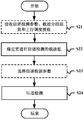
- 16 shows a flowchart of a method for wireless communication according to an embodiment of the present application, including: carrier grouping information for an unlicensed frequency band received from a base station And an uplink scheduling grant for the unlicensed band to determine a carrier group to perform channel detection (S22); and channel detecting the carrier in the determined carrier group using channel detection parameters received from the base station (S24).
- the controller 821 can be, for example, a CPU or a DSP, and operates various functions of higher layers of the base station device 820. For example, controller 821 generates data packets based on data in signals processed by wireless communication interface 825 and communicates the generated packets via network interface 823. Controller 821 can bundle data from multiple baseband processors to generate bundled packets and pass the generated bundled packets. The controller 821 can have logic functions that perform control such as radio resource control, radio bearer control, mobility management, admission control, and scheduling. This control can be performed in conjunction with nearby eNBs or core network nodes.
- the memory 822 includes a RAM and a ROM, and stores programs executed by the controller 821 and various types of control data such as a terminal list, transmission power data, and scheduling data.
- the wireless communication interface 825 can include a plurality of BB processors 826.
- multiple BB processors 826 can be compatible with multiple frequency bands used by eNB 800.
- the wireless communication interface 825 can include a plurality of RF circuits 827.
- multiple RF circuits 827 can be compatible with multiple antenna elements.
- FIG. 21 illustrates an example in which the wireless communication interface 825 includes a plurality of BB processors 826 and a plurality of RF circuits 827, the wireless communication interface 825 may also include a single BB processor 826 or a single RF circuit 827.
- the transceiving unit 102 described with reference to FIG. 1 can be implemented by the wireless communication interface 825. At least a portion of the functionality can also be implemented by controller 821. For example, the controller 821 can perform an uplink scheduling grant for each group of carriers by performing the functions of the processing circuit 101.
- the wireless communication interface 855 supports any cellular communication scheme (such as LTE and LTE-Advanced) and provides wireless communication to terminals located in sectors corresponding to the RRH 860 via the RRH 860 and the antenna 840.
- Wireless communication interface 855 can generally include, for example, BB processor 856.
- the BB processor 856 is identical to the BB processor 826 described with reference to FIG. 21 except that the BB processor 856 is connected to the RF circuit 864 of the RRH 860 via the connection interface 857.
- the wireless communication interface 855 can include a plurality of BB processors 856.
- multiple BB processors 856 can be compatible with multiple frequency bands used by eNB 830.
- FIG. 22 illustrates an example in which the wireless communication interface 855 includes a plurality of BB processors 856, the wireless communication interface 855 can also include a single BB processor 856.
- the RRH 860 includes a connection interface 861 and a wireless communication interface 863.
- connection interface 861 is an interface for connecting the RRH 860 (wireless communication interface 863) to the base station device 850.
- the connection interface 861 can also be a communication module for communication in the above high speed line.
- FIG. 23 is a block diagram showing an example of a schematic configuration of a smartphone 900 to which the technology of the present disclosure can be applied.
- the smart phone 900 includes a processor 901, a memory 902, a storage device 903, an external connection interface 904, an imaging device 906, a sensor 907, a microphone 908, an input device 909, a display device 910, a speaker 911, a wireless communication interface 912, one or more An antenna switch 915, one or more antennas 916, a bus 917, a battery 918, and an auxiliary controller 919.
- the wireless communication interface 912 supports any cellular communication scheme (such as LTE and LTE-Advanced) and performs wireless communication.
- Wireless communication interface 912 may generally include, for example, BB processor 913 and RF circuitry 914.
- the BB processor 913 can perform, for example, encoding/decoding, modulation/demodulation, and multiplexing/demultiplexing, and performs various types of signal processing for wireless communication.
- RF circuitry 914 may include, for example, mixers, filters, and amplifiers, and transmit and receive wireless signals via antenna 916.
- the wireless communication interface 912 can be a chip module on which the BB processor 913 and the RF circuit 914 are integrated. As shown in FIG.
- the wireless communication interface 912 A plurality of BB processors 913 and a plurality of RF circuits 914 may be included. Although FIG. 23 illustrates an example in which the wireless communication interface 912 includes a plurality of BB processors 913 and a plurality of RF circuits 914, the wireless communication interface 912 may also include a single BB processor 913 or a single RF circuit 914.
- wireless communication interface 912 can support additional types of wireless communication schemes, such as short-range wireless communication schemes, near field communication schemes, and wireless local area network (LAN) schemes.
- the wireless communication interface 912 can include a BB processor 913 and RF circuitry 914 for each wireless communication scheme.
- Each of the antenna switches 915 switches the connection destination of the antenna 916 between a plurality of circuits included in the wireless communication interface 912, such as circuits for different wireless communication schemes.
- Each of the antennas 916 includes a single or multiple antenna elements (such as multiple antenna elements included in a MIMO antenna) and is used by the wireless communication interface 912 to transmit and receive wireless signals.
- the smartphone 900 can include a plurality of antennas 916.
- FIG. 23 shows an example in which the smartphone 900 includes a plurality of antennas 916, the smartphone 900 may also include a single antenna 916.
- smart phone 900 can include an antenna 916 for each wireless communication scheme.
- the antenna switch 915 can be omitted from the configuration of the smartphone 900.
- the bus 917 sets the processor 901, the memory 902, the storage device 903, the external connection interface 904, the camera 906, the sensor 907, the microphone 908, the input device 909, the display device 910, the speaker 911, the wireless communication interface 912, and the auxiliary controller 919 to each other. connection.
- Battery 918 provides power to various blocks of smart phone 900 shown in FIG. 23 via a feeder, which is partially shown as a dashed line in the figure.
- the auxiliary controller 919 operates the minimum necessary function of the smartphone 900, for example, in a sleep mode.
- FIG. 24 is a block diagram showing an example of a schematic configuration of a car navigation device 920 to which the technology of the present disclosure can be applied.
- the car navigation device 920 includes a processor 921, a memory 922, a global positioning system (GPS) module 924, a sensor 925, a data interface 926, a content player 927, a storage medium interface 928, an input device 929, a display device 930, a speaker 931, and a wireless device.
- the processor 921 can be, for example, a CPU or SoC and controls the navigation functions and additional functions of the car navigation device 920.
- the memory 922 includes a RAM and a ROM, and stores data and programs executed by the processor 921.
- the GPS module 924 measures the position of the car navigation device 920 (such as latitude, longitude, and altitude) using GPS signals received from GPS satellites.
- Sensor 925 can include a set of sensors, such as a gyro sensor, a geomagnetic sensor, and an air pressure sensor.
- the data interface 926 is connected to, for example, the in-vehicle network 941 via a terminal not shown, and acquires data (such as vehicle speed data) generated by the vehicle.
- the wireless communication interface 933 supports any cellular communication scheme (such as LTE and LTE-Advanced) and performs wireless communication.
- Wireless communication interface 933 may typically include, for example, BB processor 934 and RF circuitry 935.
- the BB processor 934 can perform, for example, encoding/decoding, modulation/demodulation, and multiplexing/demultiplexing, and performs various types of signal processing for wireless communication.
- the RF circuit 935 may include, for example, a mixer, a filter, and an amplifier, and transmits and receives a wireless signal via the antenna 937.
- the wireless communication interface 933 can also be a chip module on which the BB processor 934 and the RF circuit 935 are integrated. As shown in FIG.
- Each of the antennas 937 includes a single or multiple antenna elements (such as multiple antenna elements included in a MIMO antenna) and is used for the wireless communication interface 933 to transmit and receive wireless signals.
- car navigation device 920 can include a plurality of antennas 937.
- FIG. 24 shows an example in which the car navigation device 920 includes a plurality of antennas 937, the car navigation device 920 may also include a single antenna 937.
- car navigation device 920 can include an antenna 937 for each wireless communication scheme.
- the antenna switch 936 can be omitted from the configuration of the car navigation device 920.
- the technology of the present disclosure may also be implemented as an onboard system (or vehicle) 940 that includes one or more of the car navigation device 920, the in-vehicle network 941, and the vehicle module 942.
- vehicle module 942 generates vehicle data such as vehicle speed, engine speed, and fault information, and outputs the generated data to the in-vehicle network 941.
- a storage medium for carrying a program product storing the above-described storage machine readable instruction code is also included in the disclosure of the present invention.
- the storage medium includes, but is not limited to, a floppy disk, an optical disk, a magneto-optical disk, a memory card, a memory stick, and the like.
- such a storage medium is not limited to the removable medium 2511 shown in FIG. 25 in which a program is stored and distributed separately from the device to provide a program to the user.
- the removable medium 2511 include a magnetic disk (including a floppy disk (registered trademark)), an optical disk (including a compact disk read only memory (CD-ROM) and a digital versatile disk (DVD)), and a magneto-optical disk (including a mini disk (MD) (registered) Trademark)) and semiconductor memory.
- storage media The quality may be ROM 2502, a hard disk included in the storage portion 2508, and the like, in which programs are stored, and distributed to the user together with the device containing them.
Landscapes
- Engineering & Computer Science (AREA)
- Signal Processing (AREA)
- Computer Networks & Wireless Communication (AREA)
- Mobile Radio Communication Systems (AREA)
Abstract
Priority Applications (8)
| Application Number | Priority Date | Filing Date | Title |
|---|---|---|---|
| JP2018540441A JP2019509664A (ja) | 2016-02-02 | 2017-01-25 | 無線通信システムに用いられる装置と方法、スペクトル管理装置 |
| KR1020187016991A KR20180109856A (ko) | 2016-02-02 | 2017-01-25 | 무선 통신 시스템을 위한 디바이스 및 방법과, 스펙트럼 관리 디바이스 |
| RU2018131257A RU2690014C1 (ru) | 2016-02-02 | 2017-01-25 | Устройство и способ для системы беспроводной связи и устройство управления спектром |
| AU2017215761A AU2017215761A1 (en) | 2016-02-02 | 2017-01-25 | Device and method for wireless communication system, and spectrum management device |
| EP17746937.6A EP3383085A4 (fr) | 2016-02-02 | 2017-01-25 | Dispositif et procédé destinés à un système de communication sans fil, et dispositif de gestion de spectre |
| US16/066,169 US10750539B2 (en) | 2016-02-02 | 2017-01-25 | Device and method for wireless communication system, and spectrum management device |
| CN201780005036.0A CN108605228A (zh) | 2016-02-02 | 2017-01-25 | 用于无线通信系统的装置和方法、频谱管理装置 |
| US16/902,276 US10917915B2 (en) | 2016-02-02 | 2020-06-16 | Device and method for wireless communication system, and spectrum management device |
Applications Claiming Priority (2)
| Application Number | Priority Date | Filing Date | Title |
|---|---|---|---|
| CN201610073382.XA CN107027123A (zh) | 2016-02-02 | 2016-02-02 | 用于无线通信系统的装置和方法、频谱管理装置 |
| CN201610073382.X | 2016-02-02 |
Related Child Applications (2)
| Application Number | Title | Priority Date | Filing Date |
|---|---|---|---|
| US16/066,169 A-371-Of-International US10750539B2 (en) | 2016-02-02 | 2017-01-25 | Device and method for wireless communication system, and spectrum management device |
| US16/902,276 Continuation US10917915B2 (en) | 2016-02-02 | 2020-06-16 | Device and method for wireless communication system, and spectrum management device |
Publications (1)
| Publication Number | Publication Date |
|---|---|
| WO2017133617A1 true WO2017133617A1 (fr) | 2017-08-10 |
Family
ID=59500618
Family Applications (1)
| Application Number | Title | Priority Date | Filing Date |
|---|---|---|---|
| PCT/CN2017/072599 Ceased WO2017133617A1 (fr) | 2016-02-02 | 2017-01-25 | Dispositif et procédé destinés à un système de communication sans fil, et dispositif de gestion de spectre |
Country Status (8)
| Country | Link |
|---|---|
| US (2) | US10750539B2 (fr) |
| EP (1) | EP3383085A4 (fr) |
| JP (1) | JP2019509664A (fr) |
| KR (1) | KR20180109856A (fr) |
| CN (2) | CN107027123A (fr) |
| AU (1) | AU2017215761A1 (fr) |
| RU (1) | RU2690014C1 (fr) |
| WO (1) | WO2017133617A1 (fr) |
Cited By (2)
| Publication number | Priority date | Publication date | Assignee | Title |
|---|---|---|---|---|
| KR20200086686A (ko) * | 2017-11-17 | 2020-07-17 | 소니 주식회사 | 무선 통신 시스템에서의 장치 및 방법, 및 컴퓨터-판독가능 저장 매체 |
| CN113219916A (zh) * | 2021-04-14 | 2021-08-06 | 中国科学院沈阳自动化研究所 | 基于5g的网控动态协同优化方法与架构 |
Families Citing this family (13)
| Publication number | Priority date | Publication date | Assignee | Title |
|---|---|---|---|---|
| WO2018038777A1 (fr) * | 2016-08-22 | 2018-03-01 | Intel IP Corporation | Dispositifs et procédés pour lbt de porteuse multiple elaa |
| CN108513734A (zh) * | 2017-08-30 | 2018-09-07 | 深圳市大疆创新科技有限公司 | 一种信道切换方法、装置及通信设备 |
| CN109788427A (zh) * | 2017-11-10 | 2019-05-21 | 索尼公司 | 无线通信系统中的装置和方法、计算机可读存储介质 |
| EP3771247B1 (fr) | 2018-03-21 | 2023-05-10 | Guangdong Oppo Mobile Telecommunications Corp., Ltd. | Procédé et dispositif de transmission d'informations |
| CN110769463A (zh) * | 2018-07-27 | 2020-02-07 | 索尼公司 | 电子装置、无线通信方法和计算机可读介质 |
| US11272540B2 (en) | 2018-08-09 | 2022-03-08 | Ofinno, Llc | Channel access and uplink switching |
| US11272539B2 (en) | 2018-08-09 | 2022-03-08 | Ofinno, Llc | Channel access and bandwidth part switching |
| CN112740810A (zh) | 2018-09-27 | 2021-04-30 | Oppo广东移动通信有限公司 | 检测信道、发送信息的方法和设备 |
| EP4023022B1 (fr) * | 2019-08-26 | 2023-05-31 | Telefonaktiebolaget LM Ericsson (publ) | Détection d'énergie flexible dans un spectre sans licence |
| CN116158152B (zh) * | 2020-07-27 | 2026-04-21 | 恩梯梯株式会社 | 基站以及终端 |
| KR20230048064A (ko) * | 2020-09-11 | 2023-04-10 | 주식회사 윌러스표준기술연구소 | 멀티 링크를 사용하는 무선 통신 방법 및 이를 사용하는 무선 통신 단말 |
| CN114286446B (zh) * | 2021-12-14 | 2025-08-22 | 深圳市联平半导体有限公司 | 无线宽带信号的接收端与通信系统 |
| EP4539587A4 (fr) * | 2022-07-18 | 2025-10-01 | Samsung Electronics Co Ltd | Dispositif électronique pour effectuer une opération sur la base d'une latence d'une pluralité de liaisons, et procédé de fonctionnement d'un dispositif électronique |
Citations (5)
| Publication number | Priority date | Publication date | Assignee | Title |
|---|---|---|---|---|
| WO2010102456A1 (fr) * | 2009-03-13 | 2010-09-16 | 华为技术有限公司 | Procédé de distribution de ressources, procédé de transmission de données, station de base et terminal |
| CN104869653A (zh) * | 2014-02-23 | 2015-08-26 | 上海朗帛通信技术有限公司 | 一种基站、ue中非授权频谱上的调度方法和设备 |
| CN105049136A (zh) * | 2015-08-07 | 2015-11-11 | 宇龙计算机通信科技(深圳)有限公司 | 一种非授权频谱信道检测方法和装置 |
| CN105072690A (zh) * | 2015-09-06 | 2015-11-18 | 魅族科技(中国)有限公司 | 基于非授权频谱的数据传输方法及装置 |
| WO2016013779A1 (fr) * | 2014-07-25 | 2016-01-28 | 주식회사 케이티 | Procédé de réception d'informations de programmation de cellule de spectre sans licence, et dispositif associé |
Family Cites Families (27)
| Publication number | Priority date | Publication date | Assignee | Title |
|---|---|---|---|---|
| US8520589B2 (en) * | 2008-05-19 | 2013-08-27 | Motorola Mobility Llc | Mobile device and method for intelligently communicating data generated thereby over short-range, unlicensed wireless networks and wide area wireless networks |
| KR20160147920A (ko) * | 2014-04-29 | 2016-12-23 | 후아웨이 테크놀러지 컴퍼니 리미티드 | 랜덤 액세스 장치 및 방법 |
| US9860776B2 (en) * | 2014-06-20 | 2018-01-02 | Qualcomm Incorporated | Method and apparatus for reducing self-jamming of transmissions on adjacent carriers |
| WO2016045108A1 (fr) * | 2014-09-26 | 2016-03-31 | 宇龙计算机通信科技(深圳)有限公司 | Procédé et système de transmission de données, et dispositif ayant une fonction de station de base |
| CN105634699B (zh) * | 2014-11-07 | 2020-08-11 | 中兴通讯股份有限公司 | 载波选择方法及装置、接入点 |
| EP3203794B1 (fr) * | 2014-11-26 | 2021-11-10 | Nanchang Coolpad Intelligent Technology Company Limited | Coexistence de lte et autre systemes |
| CN104333873A (zh) * | 2014-11-28 | 2015-02-04 | 东莞宇龙通信科技有限公司 | 信道检测方法及系统、具有基站功能的设备和终端 |
| CN104540158B (zh) * | 2015-01-12 | 2018-12-25 | 宇龙计算机通信科技(深圳)有限公司 | 信道检测通知方法、系统和基站 |
| CN106160966B (zh) * | 2015-03-30 | 2021-01-26 | 中兴通讯股份有限公司 | 数据发送方法、占用信号的发送方法及装置 |
| CN114095996A (zh) * | 2015-05-15 | 2022-02-25 | 北京三星通信技术研究有限公司 | 一种上行功率的分配方法和用户设备 |
| CN106453182B (zh) * | 2015-08-07 | 2020-06-09 | 中兴通讯股份有限公司 | 前导发送方法和装置 |
| CN106452708B (zh) * | 2015-08-07 | 2021-07-06 | 中兴通讯股份有限公司 | 一种非授权多载波先听后说执行方法和装置 |
| CN112953691B (zh) * | 2015-08-13 | 2024-12-31 | 索尼公司 | 无线通信系统中的电子设备和无线通信方法 |
| CN107980240B (zh) * | 2015-08-14 | 2021-06-11 | 瑞典爱立信有限公司 | 信道接入配置 |
| JP6637163B2 (ja) * | 2015-09-17 | 2020-01-29 | エルジー エレクトロニクス インコーポレイティド | 非免許帯域を支援する無線接続システムにおいてマルチキャリア上でlbt過程を行う方法及び装置 |
| US11064521B2 (en) * | 2015-10-19 | 2021-07-13 | Apple Inc. | Scheduling uplink transmissions for a user equipment (UE) |
| CN106656430B (zh) * | 2015-10-28 | 2020-08-25 | 中兴通讯股份有限公司 | 先听后说参数处理方法、竞争窗调整方法和装置 |
| CN107027127A (zh) * | 2016-02-02 | 2017-08-08 | 索尼公司 | 信道检测装置和方法、用户设备和基站 |
| US10880921B2 (en) * | 2016-02-04 | 2020-12-29 | Comcast Cable Communications, Llc | Detection threshold for a wireless network |
| CN107046731A (zh) * | 2016-02-05 | 2017-08-15 | 索尼公司 | 无线通信系统中的电子设备和无线通信方法 |
| US10764913B2 (en) * | 2016-03-24 | 2020-09-01 | Qualcomm Incorporated | Techniques for assisting performance of listen before talk procedures and uplink traffic multiplexing at user equipment |
| KR20170112945A (ko) * | 2016-04-01 | 2017-10-12 | 삼성전자주식회사 | 이동통신 시스템에서 기기 간 통신과 셀룰라 통신의 공존 방법 및 장치 |
| US10681733B2 (en) * | 2016-07-26 | 2020-06-09 | Qualcomm Incorporated | License assisted request-to-send and clear-to-send transmission |
| EP3493574B1 (fr) * | 2016-08-11 | 2023-04-12 | Huawei Technologies Co., Ltd. | Procédé de communication sans fil basé sur un spectre de fréquences sans licence, station de base et dispositif terminal |
| CN107734560B (zh) * | 2016-08-12 | 2023-09-15 | 中兴通讯股份有限公司 | 信号传输方法、通信设备及通信系统 |
| CN106454910B (zh) * | 2016-09-09 | 2022-09-02 | 宇龙计算机通信科技(深圳)有限公司 | 通信方法、通信装置和终端 |
| JP2019216295A (ja) * | 2016-10-18 | 2019-12-19 | シャープ株式会社 | 基地局装置、端末装置および通信方法 |
-
2016
- 2016-02-02 CN CN201610073382.XA patent/CN107027123A/zh active Pending
-
2017
- 2017-01-25 AU AU2017215761A patent/AU2017215761A1/en not_active Abandoned
- 2017-01-25 CN CN201780005036.0A patent/CN108605228A/zh active Pending
- 2017-01-25 JP JP2018540441A patent/JP2019509664A/ja active Pending
- 2017-01-25 WO PCT/CN2017/072599 patent/WO2017133617A1/fr not_active Ceased
- 2017-01-25 US US16/066,169 patent/US10750539B2/en active Active
- 2017-01-25 KR KR1020187016991A patent/KR20180109856A/ko not_active Withdrawn
- 2017-01-25 EP EP17746937.6A patent/EP3383085A4/fr not_active Withdrawn
- 2017-01-25 RU RU2018131257A patent/RU2690014C1/ru active IP Right Revival
-
2020
- 2020-06-16 US US16/902,276 patent/US10917915B2/en active Active
Patent Citations (5)
| Publication number | Priority date | Publication date | Assignee | Title |
|---|---|---|---|---|
| WO2010102456A1 (fr) * | 2009-03-13 | 2010-09-16 | 华为技术有限公司 | Procédé de distribution de ressources, procédé de transmission de données, station de base et terminal |
| CN104869653A (zh) * | 2014-02-23 | 2015-08-26 | 上海朗帛通信技术有限公司 | 一种基站、ue中非授权频谱上的调度方法和设备 |
| WO2016013779A1 (fr) * | 2014-07-25 | 2016-01-28 | 주식회사 케이티 | Procédé de réception d'informations de programmation de cellule de spectre sans licence, et dispositif associé |
| CN105049136A (zh) * | 2015-08-07 | 2015-11-11 | 宇龙计算机通信科技(深圳)有限公司 | 一种非授权频谱信道检测方法和装置 |
| CN105072690A (zh) * | 2015-09-06 | 2015-11-18 | 魅族科技(中国)有限公司 | 基于非授权频谱的数据传输方法及装置 |
Non-Patent Citations (1)
| Title |
|---|
| See also references of EP3383085A4 * |
Cited By (6)
| Publication number | Priority date | Publication date | Assignee | Title |
|---|---|---|---|---|
| KR20200086686A (ko) * | 2017-11-17 | 2020-07-17 | 소니 주식회사 | 무선 통신 시스템에서의 장치 및 방법, 및 컴퓨터-판독가능 저장 매체 |
| JP2021503830A (ja) * | 2017-11-17 | 2021-02-12 | ソニー株式会社 | 無線通信システムにおける装置及び方法、並びにコンピュータ可読記憶媒体 |
| JP7200993B2 (ja) | 2017-11-17 | 2023-01-10 | ソニーグループ株式会社 | 無線通信システムにおける装置及び方法 |
| KR102844581B1 (ko) * | 2017-11-17 | 2025-08-11 | 소니그룹주식회사 | 무선 통신 시스템에서의 장치 및 방법, 및 컴퓨터-판독가능 저장 매체 |
| US12507226B2 (en) | 2017-11-17 | 2025-12-23 | Sony Group Corporation | Apparatus and method in wireless communication system, and computer-readable storage medium |
| CN113219916A (zh) * | 2021-04-14 | 2021-08-06 | 中国科学院沈阳自动化研究所 | 基于5g的网控动态协同优化方法与架构 |
Also Published As
| Publication number | Publication date |
|---|---|
| RU2690014C1 (ru) | 2019-05-30 |
| JP2019509664A (ja) | 2019-04-04 |
| EP3383085A4 (fr) | 2018-11-14 |
| CN107027123A (zh) | 2017-08-08 |
| US10750539B2 (en) | 2020-08-18 |
| EP3383085A1 (fr) | 2018-10-03 |
| US20180376506A1 (en) | 2018-12-27 |
| AU2017215761A1 (en) | 2018-04-12 |
| US20200314907A1 (en) | 2020-10-01 |
| KR20180109856A (ko) | 2018-10-08 |
| US10917915B2 (en) | 2021-02-09 |
| CN108605228A (zh) | 2018-09-28 |
Similar Documents
| Publication | Publication Date | Title |
|---|---|---|
| US10917915B2 (en) | Device and method for wireless communication system, and spectrum management device | |
| US11729777B2 (en) | Channel detection apparatus and method, user equipment, and base station | |
| CN111052773B (zh) | 无线通信系统中的装置和方法、计算机可读存储介质 | |
| CN106452705B (zh) | 无线通信系统中的电子设备和无线通信方法 | |
| RU2691199C1 (ru) | Способы и устройства стороны базовой станции и стороны устройства пользователя и система беспроводной связи | |
| CN114222372B (zh) | 用于无线通信的电子设备和方法 | |
| EP3145268B1 (fr) | Appareil de gestion de spectre | |
| CN108432152B (zh) | 无线通信系统中的电子设备和无线通信方法 | |
| WO2017167165A1 (fr) | Dispositif électronique, appareil de traitement d'informations et procédé de traitement d'informations | |
| EP3407636A1 (fr) | Appareil et procédé pour une gestion de spectre, appareil et procédé pour un côté station de base et un côté équipement utilisateur | |
| CN113891328A (zh) | 电子设备及用于电子设备的方法、计算机可读存储介质 | |
| CN119922734A (zh) | 一种通信方法及装置 | |
| CN117378166A (zh) | 电子设备、无线通信方法以及计算机可读存储介质 |
Legal Events
| Date | Code | Title | Description |
|---|---|---|---|
| 121 | Ep: the epo has been informed by wipo that ep was designated in this application |
Ref document number: 17746937 Country of ref document: EP Kind code of ref document: A1 |
|
| ENP | Entry into the national phase |
Ref document number: 2017215761 Country of ref document: AU Date of ref document: 20170125 Kind code of ref document: A |
|
| ENP | Entry into the national phase |
Ref document number: 20187016991 Country of ref document: KR Kind code of ref document: A |
|
| ENP | Entry into the national phase |
Ref document number: 2018540441 Country of ref document: JP Kind code of ref document: A |
|
| NENP | Non-entry into the national phase |
Ref country code: DE |