WO2017134740A1 - Stator et compresseur - Google Patents
Stator et compresseur Download PDFInfo
- Publication number
- WO2017134740A1 WO2017134740A1 PCT/JP2016/053013 JP2016053013W WO2017134740A1 WO 2017134740 A1 WO2017134740 A1 WO 2017134740A1 JP 2016053013 W JP2016053013 W JP 2016053013W WO 2017134740 A1 WO2017134740 A1 WO 2017134740A1
- Authority
- WO
- WIPO (PCT)
- Prior art keywords
- electromagnetic steel
- hole
- protrusion
- stator
- split
- Prior art date
- Legal status (The legal status is an assumption and is not a legal conclusion. Google has not performed a legal analysis and makes no representation as to the accuracy of the status listed.)
- Ceased
Links
Images










Classifications
-
- H—ELECTRICITY
- H02—GENERATION; CONVERSION OR DISTRIBUTION OF ELECTRIC POWER
- H02K—DYNAMO-ELECTRIC MACHINES
- H02K1/00—Details of the magnetic circuit
- H02K1/06—Details of the magnetic circuit characterised by the shape, form or construction
- H02K1/12—Stationary parts of the magnetic circuit
- H02K1/18—Means for mounting or fastening magnetic stationary parts on to, or to, the stator structures
Definitions
- the present invention relates to a stator of an electric motor for a compressor and a compressor.
- the hermetic compressor includes a compression mechanism unit that compresses refrigerant, an electric mechanism unit that drives the compression mechanism unit, and a sealed container that houses the compression mechanism unit and the electric mechanism unit.
- the electric mechanism unit includes a rotor and a cylindrical stator provided outside the rotor.
- the stator is composed of a stator core in which electromagnetic steel plates are laminated and a stator winding.
- the stator core is composed of a back yoke that forms a cylindrical portion of the outer edge, and teeth that are provided inside the back yoke and wind the stator winding.
- the loss of the electric mechanism part includes iron loss caused by loss of magnetic flux and copper loss caused by current flowing in the stator winding. Copper loss is reduced by using a thick wire for the stator winding and reducing electrical resistance.
- the winding space of the stator needs to be large enough that the winding jig does not come into contact with or interfere with the stator when the winding is wound around the stator. If a wire having a large wire diameter is wound as a stator winding in a state where the winding space of the stator is not sufficient, the necessary number of turns cannot be wound. As a result, the electric mechanism unit cannot generate a necessary torque.
- stator core As a method of expanding the winding space of the stator, for example, there is a method of dividing the stator core.
- the cylindrical stator core is divided by the back yoke, and the winding is wound around the teeth. Thereafter, the divided stator cores are joined to form one stator core.
- the joints are joined by welding.
- a joining method other than welding for example, as disclosed in Patent Document 1, one of the joint portions of the stator core includes a fitting concave portion and a fitting convex portion on the other, and the fitting concave portion and the fitting convex portion are provided.
- the cylindrical stator iron core is formed by fitting the parts.
- the divided stator iron cores can be combined and integrated.
- a convex portion and a concave portion are provided at the back yoke end portion of the divided stator core, and the stator cores divided in advance are pivotally attached to each other by the convex portion and the concave portion.
- the stator cores divided by the rotation support portion are connected while forming the rotation support portion.
- the divided stator cores are connected and then formed into a cylindrical shape.
- JP2011-188650 (7th and 8th pages, FIGS. 1 to 6) JP2009-118676 (4th, 5th page, FIGS. 7 to 11) Japanese Patent Laid-Open No. 2001-95181 (pages 3, 4 and 1 to 9)
- Uneven rotation speed of the electric mechanism part of the hermetic compressor causes noise generation and efficiency reduction.
- the stator is close to a perfect circular cylinder and the teeth are aligned at equal intervals.
- the electric mechanism portion is fixed by press-fitting, welding, shrink fitting, or the like when incorporated in the sealed container, the stator is distorted and deformed from a perfect circular cylindrical shape.
- the stator core is divided and formed, distortion occurs at the joint.
- the hermetic container applies a load to the stator core, parts constituting the stator core try to move in the radial direction and the circumferential direction.
- the expansion and contraction of the sealed container places a load on the stator core, and the components constituting the stator core tend to move in the radial direction and the circumferential direction.
- shrink fitting the stator of the electric mechanism section is deformed by the load that the components constituting the stator core are about to move in the radial direction and the circumferential direction, generating noise and reducing efficiency.
- stator core When the stator core is divided, welding is performed to join the divided stator cores, so that the stator core is deformed by the heat.
- a plurality of divided iron cores formed by laminating a plurality of electromagnetic steel sheets are connected in the circumferential direction, and fixed in a cylindrical shape.
- the divided stator cores are connected in a cylindrical shape without welding, and the connecting part relaxes the load and stress when incorporated in a sealed container, and suppresses deformation in the radial and circumferential directions. It provides a child iron core.
- the stator iron core according to the present invention is formed by laminating a plurality of electromagnetic steel plates, and connects a plurality of back yokes of a divided iron core having teeth and a back yoke in a circumferential direction at a connecting portion of the back yoke,
- the split iron core has an arc-shaped protrusion on one side of the circumferential end of the back yoke and an arc-shaped hole on the side opposite to the side where the projection is disposed on the other circumferential end of the back yoke.
- the connecting portion is configured such that the projection of another adjacent split core is fitted into the hole of one split core, and the arc-shaped outer peripheral surface of the projection is in contact with and engages the arc-shaped inner wall of the hole. .
- the connecting portion of the split core is configured so that the arc-shaped outer peripheral surface of the protrusion is in contact with and engages the arc-shaped inner wall of the hole, so that the split core is not welded. It can be connected and rotated at the connecting portion to form a cylindrical shape. And when it incorporates in an airtight container by the connection part, the load and stress concerning a stator core can be relieve
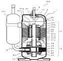
- FIG. 1 is a longitudinal sectional view showing the inside of a hermetic rotary compressor according to Embodiment 1 for carrying out the present invention, that is, a view seen from the radial direction of a crankshaft.
- the hermetic compressor 100 includes a hermetic container 1 in which a compression mechanism 2 and an electric mechanism 3 are housed.
- the sealed container 1 includes an upper container 11 and a lower container 12.
- the compression mechanism unit 2 is disposed at the lower part of the sealed container 1, and the electric mechanism unit 3 is disposed at the upper part of the sealed container 1.
- the compression mechanism unit 2 and the electric mechanism unit 3 are connected by a crankshaft 4.
- the compression mechanism unit 2 is rotationally driven by the electric mechanism unit 3 via the crankshaft 4.
- Refrigerating machine oil is stored in the lower portion of the hermetic container 1 and supplied to the sliding portion of the compression mechanism section 2.
- the refrigerating machine oil is used for lubrication of sliding portions of the compression mechanism section 2 and sealing of gaps.
- the crankshaft 4 includes a main shaft portion 41, a sub shaft portion 42, and an eccentric shaft portion 43.
- the crankshaft 4 is provided in the axial direction of the crankshaft 4 in the order of the main shaft portion 41, the eccentric shaft portion 43, and the auxiliary shaft portion 42.
- shaft part 41 and the subshaft part 42 is provided so that it may correspond, ie, coaxially.
- the center of the shaft of the eccentric shaft portion 43 is shifted from the center of the shaft of the main shaft portion 41 and the sub shaft portion 42. Accordingly, when the main shaft portion 41 and the sub shaft portion 42 rotate around the center of the shaft, the eccentric shaft portion 43 rotates eccentrically.
- the crankshaft 4 is rotatably supported by two bearings.
- the compression mechanism part 2 is demonstrated in FIG. 1 and FIG.
- the compression mechanism unit 2 includes a cylinder 21, a rolling piston 22, a main bearing 23, a sub bearing 24, and a vane 25.
- the cylinder 21 is provided with a cylindrical internal space, that is, a cylinder chamber 26. Both ends in the axial direction of the cylinder chamber 26 are open to the outside of the cylinder 21.
- a main bearing 23 is attached to one opening of the cylinder chamber 26. The opening is closed by the main bearing 23.
- a sub bearing 24 is attached to the other opening of the cylinder chamber 26. And the subbearing 24 has obstruct
- the main bearing 23 and the auxiliary bearing 24 are fixed to the cylinder 21 with bolts or the like. In the cylinder chamber 26, the eccentric shaft portion 43 of the crankshaft 4, the rolling piston 22, and the vane 25 are accommodated.
- FIG. 2 is a cross-sectional view of the compression mechanism section 2 cut along a plane perpendicular to the crankshaft 4.
- a vane groove 27 is provided in the cylinder 21 in the radial direction from the center of the cylinder chamber 26.
- the vane groove 27 opens into the cylinder chamber 26.
- the vane 25 is stored in the vane groove 27.
- the vane 25 has a substantially rectangular parallelepiped shape.
- a back pressure chamber 28 is provided on the opposite side of the vane groove 27 from the opening of the cylinder chamber 26.
- the back pressure chamber 28 is provided with a spring.
- One of the springs is in contact with the end face of the vane.
- the vane 25 is pushed out from the vane groove 27 to the cylinder chamber 26 by the spring.
- the tip of the vane 25 is in contact with and pressed against the outer peripheral surface of the rolling piston 22.
- the space formed by the inner peripheral surface of the inner diameter of the cylinder chamber 26, the outer peripheral surface of the outer diameter of the rolling piston 22, the main bearing 23, and the auxiliary bearing 24 is divided into two working chambers by the vanes 25. It is divided into.
- the rolling piston 22 has a ring shape and is rotatably mounted on the eccentric shaft portion 43.
- the rolling piston 22 rotates eccentrically in the cylinder chamber 26 together with the eccentric shaft portion 43 as the crankshaft 4 rotates.
- the vane 25 in contact with the rolling piston 22 reciprocates in the vane groove 27.
- Both the main bearing 23 and the sub-bearing 24 are composed of a cylindrical bearing portion and a flat end plate portion orthogonal to the bearing portion.
- the main shaft portion 41 of the crankshaft 4 is inserted into the bearing portion of the main bearing 23.
- the bearing portion of the main bearing 23 supports the main shaft portion 41.
- the auxiliary shaft portion 42 of the crankshaft 4 is inserted into the bearing portion of the auxiliary bearing 24.
- the bearing portion of the auxiliary bearing 24 supports the auxiliary shaft portion 42.
- One end of the cylinder chamber 26 is closed by the end plate of the main bearing 23.
- the other opening of the cylinder chamber 26 is closed by the end plate portion of the auxiliary bearing 24.
- the cylinder 21 is provided with a flow path that communicates with the outside of the sealed container 1 and the cylinder chamber 26, that is, a suction port.
- the suction port is a hole provided in the cylinder 21.
- the suction port communicates with one working chamber in which the cylinder chamber 26 is divided by the vane 25.
- the cylinder 21 sucks refrigerant gas from the outside of the hermetic container 1 into one working chamber through the suction port.
- the cylinder 21 is provided with a flow path that communicates with the outside of the cylinder 21 and the cylinder chamber 26, that is, a discharge port.
- the discharge port is also a hole provided in the cylinder 21.
- the discharge port communicates with the other working chamber in which the cylinder chamber 26 is divided by the vane 25.
- the main bearing 23 is provided with a flow path and an opening that communicate with the discharge port, that is, a discharge port.
- the discharge port communicates the working chamber of the cylinder 21 and the external space of the cylinder 21 via the discharge port.
- a discharge valve is provided at the discharge port. The discharge valve closes until the refrigerant in the working chamber reaches a predetermined pressure, and opens when the refrigerant in the working chamber reaches a predetermined pressure or more.
- the main bearing 23 is provided with a discharge muffler 29 that covers the main bearing 23.
- the discharge muffler 29 is attached to the main bearing 23 with bolts or the like.
- a space, that is, a muffler chamber is provided between the main bearing 23 and the discharge muffler 29.
- the refrigerant gas discharged from the discharge port of the main bearing 23 diffuses into the muffler chamber. Discharge noise is suppressed by once diffusing the refrigerant gas compressed in the cylinder 21 into the muffler chamber.
- the discharge muffler 29 is also provided in the auxiliary bearing 24. Further, when both have discharge ports, they are provided on both the main bearing 23 and the auxiliary bearing 24.
- the discharge muffler 29 is provided with an opening 30.
- the opening 30 communicates the muffler chamber and the space between the discharge muffler 29 and the sealed container 1. Thereby, the refrigerant gas compressed in the cylinder chamber 26 is discharged into the sealed container 1 through the discharge muffler 29.
- the refrigerant gas discharged from the discharge muffler 29 into the sealed container 1 is sent above the sealed container 1. At that time, the refrigerant gas passes through the gap of the electric mechanism unit 2.
- a discharge pipe 5 is provided in the upper container 11 of the sealed container 1.
- a refrigerant circuit provided outside the sealed container 1 is connected to the discharge pipe 5.
- the refrigerant gas compressed by the compression mechanism unit 3 is discharged from the discharge pipe 5 to the refrigerant circuit outside the sealed container 1.
- a suction muffler 101 is provided outside the sealed container 1.
- the suction muffler 101 and the suction port of the cylinder 21 are connected by a suction pipe 6.
- the suction muffler 101 is connected to a refrigerant circuit provided outside the sealed container 1 via a pipe 102.
- the suction muffler 101 is hollow inside. The hollow space communicates with the pipe 102 and the suction pipe 6.
- the refrigerant gas sucked from the pipe 102 is diffused into the hollow space of the suction muffler 101, and only the refrigerant gas is sucked into the cylinder 21 from the suction pipe 6. Thereby, the liquid refrigerant is separated from the refrigerant gas, and only the refrigerant gas is sucked into the cylinder 21.
- a condenser 103, an expansion valve 104, and an evaporator 105 are provided outside the hermetic compressor 100 to form a refrigeration circuit. It is shown in FIG. That is, in the air conditioner, the discharge pipe 5 of the hermetic compressor 100 is connected to the suction muffler 101 via the condenser 103, the expansion valve 104, and the evaporator 105.
- the discharge pipe 5, the condenser 103, the expansion valve 104, the evaporator 105, and the suction muffler 101 are connected by piping.
- the pipe is a copper pipe. The refrigerant circulates in this circuit.
- the refrigerant exchanges heat with air, water, etc., and performs heat absorption and heat dissipation. That is, the refrigerant that has absorbed heat in the evaporator 105 is carried to the condenser 103 and is radiated by the condenser 103. The refrigerant radiated by the condenser 103 is carried to the evaporator 105 and again absorbs heat. By circulating in the circuit in this way, heat energy is conveyed.
- Reference numeral 106 denotes a four-way valve that reverses the route through which the refrigerant circulates.
- the refrigerant discharged from the hermetic compressor 100 flows in the order of the condenser 103, the expansion valve 104, the evaporator 105, and the suction muffler 101, and returns to the hermetic compressor 100 by the four-way valve 106.
- the refrigerant discharged from the machine 100 is switched so as to flow in the order of the evaporator 105, the expansion valve 104, the condenser 103, and the suction muffler 101 and return to the hermetic compressor 100.
- the conveyance of heat energy is reversed to switch between cooling and heating.
- the function of the condenser 103 is an evaporator
- the function of the evaporator 105 is a condenser.
- the discharge port When the discharge port is opened, the high-pressure and high-temperature refrigerant gas in the working chamber is discharged into the discharge muffler 29 through the discharge port.
- the refrigerant gas discharged into the discharge muffler 29 is discharged from the discharge muffler 29 into the sealed container 1.
- the rolling piston 22 rotates eccentrically, the communication with the discharge port is cut off and the communication with the suction port is made again. A series of operations are performed while the rolling piston 22 makes one rotation in the cylinder chamber 26. Of the two working chambers provided by the vane 25, when one working chamber is sucking the refrigerant gas, the other is an operation of discharging the refrigerant gas.
- the working chamber has the vane 25 in between, the working chamber in which the suction port communicates and sucks the low-pressure refrigerant gas is the suction chamber in the low-pressure space, and the working chamber in which the discharge port communicates and discharges the high-pressure refrigerant gas is It becomes a compression chamber of high-pressure space.
- the rotational force of the rolling piston 22, that is, the crankshaft 4 is obtained from the electric mechanism unit 3.
- the electric mechanism unit 3 includes a rotor 31 and a stator 32 provided so as to surround the outside of the rotor 31.
- the rotor 31 has a cylindrical shape and is fixed to the main shaft portion 41 of the crankshaft 4.
- the rotor 31 is composed of a rotor core 31a.
- the rotor core 31 a is formed by stacking thin electromagnetic steel plates in the axial direction of the crankshaft 4.
- the electromagnetic steel sheet has a thickness of 0.1 mm to 1.5 mm. Electrical steel sheets are mainly made of iron.
- the rotor core 31a is formed by punching the electromagnetic steel sheets into a certain shape and stacking a plurality of them in the axial direction. Stacked electrical steel sheets are fixed by caulking or welding.
- An upper balance weight 31b is provided at the upper part of the rotor core 31a, and a lower balance weight 31c is provided at the lower part.
- the upper balance weight 31b and the lower balance weight 31c are provided to cancel the load when the eccentric shaft portion 43 of the crankshaft 4 rotates eccentrically.
- the upper balance weight 31b, the lower balance weight 31c, and the rotor core 31a are fixed by rivets 31d.
- the rotor core 31a is provided with a rivet hole penetrating in the axial direction.
- the upper balance weight 31b and the lower balance weight 31c are also provided with rivet holes. A rivet 31d is inserted into these rivet holes and fixed. Note that when the eccentric shaft portion 43 of the crankshaft 4 is eccentrically rotated and the load does not need to be canceled, end plates are attached instead of the upper balance weight 31b and the lower balance weight 31c. .
- the rotor 31 is provided with a shaft hole penetrating in the axial direction on the central axis of the rotor 31.
- the main shaft portion 41 of the crankshaft 4 is inserted and fixed in the shaft hole of the rotor 31.
- the rotor 31 has a different structure depending on the type of the electric mechanism unit 3.
- a DC motor has a permanent magnet
- an AC motor has a secondary winding.
- 1 and 4 are examples of DC motors.
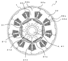
- FIG. 4 is a cross-sectional view of the electric mechanism unit 3 cut along a plane perpendicular to the crankshaft 4.
- the rotor 31 is provided with a magnet hole penetrating in the axial direction so as to surround the shaft hole.
- a permanent magnet 31e is inserted and fixed in the magnet hole.
- an even number of magnet holes and permanent magnets 31e are provided.
- the magnet hole and the permanent magnet 31 e are provided in the outer peripheral portion of the rotor 31 in the radial direction, that is, in the vicinity of the outer peripheral surface of the rotor 31 in the radial direction.
- a ferrite magnet or a rare earth magnet is used for the permanent magnet 31e.
- the magnet shape includes an arc shape, a flat plate shape and the like according to the characteristics of the material. Moreover, although the thing of the structure which has a magnet hole has been demonstrated, there exists a thing of the structure where the magnet was adhere
- a secondary winding is provided on the stator.
- the secondary winding includes a plurality of columnar conductive materials penetrating in the axial direction and a ring-shaped conductive material that connects the plurality of conductive materials at the end surfaces in the axial direction.
- the columnar conductive material and the ring-shaped conductive material are integrally formed of aluminum.
- the generated secondary winding is shaped like a ridge.
- the upper balance weight 31b and the lower balance weight 31c are fixed to the end face of the ring-shaped conductive portion.
- the rotor of the AC motor generates magnetic flux by the induced current generated in the secondary winding.
- the rotor 31 rotates around the central axis, that is, the crankshaft 4 by the magnetic flux generated by the stator 32 and the magnetic flux generated by the rotor 31.
- a communication hole 31f penetrating in the axial direction is provided between the magnet hole and the shaft hole or between the secondary winding and the shaft hole.
- the refrigerant gas discharged from the discharge muffler 29 is guided to the discharge pipe 5 by using the gap between the rotor 31 and the stator 32, the gap between the windings of the stator 32, and the communication hole 31f.
- the refrigerant gas discharged from the compression mechanism unit 2 contains and dissolves refrigerating machine oil stored in the lower part of the sealed container 1. If the refrigerating machine oil is discharged out of the sealed container 1 while being dissolved in the refrigerant gas, the refrigerating machine oil in the sealed container 1 is depleted and the refrigerating machine oil is not supplied to the compression mechanism unit 2. If the refrigerating machine oil is not supplied to the compression mechanism part 2, the gap in the compression mechanism part 2 is insufficiently sealed, the refrigerant gas leaks, the lubricity of the sliding part of the compression mechanism part 2 decreases, and a failure occurs. Or Therefore, refrigeration oil is separated from the refrigerant gas and returned to the lower part of the sealed container.
- an oil separation plate 31 g is provided between the opening of the communication hole 31 f and the discharge pipe 5.
- the oil separation plate 31g is fixed to the crankshaft 4.
- a shaft hole is provided at the center of the oil separation plate 31g.
- the main shaft portion 41 of the crankshaft 4 is inserted and fixed in the shaft hole.
- the oil separation plate 31g is a flat plate and generally has a disk shape. However, it may be rectangular or polygonal.
- the disc-shaped portion of the oil separation plate 31g is projected and fixed so as to cover the upper part in the axial direction of the opening of the communication hole 31f.
- the refrigerant gas sucked from one of the communication holes 31f is discharged from the other and collides with the oil separation plate 31g.
- the refrigerant gas passing through the gaps has a slower flow velocity than the communication holes 31f. Therefore, the refrigerant gas and the refrigerating machine oil are separated while passing through the gap.
- the refrigerant gas passing through the communication hole 31f has a higher flow velocity than the gaps other than the communication hole 31f. Therefore, it passes through the communication hole 31f before being separated into the refrigerant gas and the refrigerating machine oil.
- the refrigerant gas is discharged from the communication hole 31f. When the refrigerant gas is sent out from the discharge pipe 5 as it is, the refrigerating machine oil is taken out of the sealed container 1.
- the refrigerant gas discharged from the communication hole 31f collides with the oil separation plate 31g.
- the refrigerant gas is separated into refrigerant gas and refrigerating machine oil by colliding with the oil separation plate 31g.
- the refrigerant gas having a low specific gravity flows upward, and the refrigerating machine oil having a high specific gravity is returned downward.
- the oil separation plate 31g suppresses the amount that the refrigerating machine oil is taken out of the sealed container 1.
- the stator 32 has a cylindrical shape as a whole, and a rotor 31 is provided inside.
- the rotor 31 and the stator 32 are installed through a gap of 0.3 mm to 1.0 mm.
- the stator 32 includes a stator core 32 a in which thin electromagnetic steel plates are stacked in the axial direction of the crankshaft 4.
- the stator core 32a is composed of a back yoke 32b constituting a cylindrical portion of the outer edge, and a plurality of teeth 32c provided inside the back yoke 32b.
- the teeth 32c extend toward the central axis of the stator core 32a, that is, toward the crankshaft 4.
- the tip extends in an inverted arc shape so as to face the outer peripheral surface of the rotor.
- a slot 32e occupied by the stator winding 32d is formed between the teeth 32c and the teeth 32c.
- a stator winding 32d is wound around the teeth 32c via an insulating member 32f.
- the concentrated winding method is a configuration and method in which the stator winding 32d is wound around each tooth 32c.
- One magnetic pole is formed on one tooth 32c.
- Distributed winding is a configuration and method in which the stator winding 32d is wound over a plurality of teeth 32c.
- a plurality of teeth 32c form one magnetic pole.
- the method shown in FIG. 4 is a concentrated winding method. The concentrated winding method will be described as an example.
- the stator winding 32d is composed of a core wire and at least one layer of coating covering the core wire.
- the material of the core wire is mainly copper, but may be aluminum.
- the material of the coating is AI (amidoimide) / EI (ester imide).
- the stator 32 generates a magnetic flux for each tooth 32c by passing a current through the stator winding 32d.
- the insulating member 32f insulates the stator core 32a mainly made of iron from the stator winding 32d made of copper. Between the stator core 32a and the stator winding 32d, a refrigerant having a lower dielectric constant than that in vacuum or refrigeration oil passes, so that the dielectric constant therebetween decreases. As the density of the refrigerant increases, the dielectric constant decreases. The decrease in dielectric constant causes an increase in leakage current when a current is passed through the stator winding 32d. Therefore, an insulating member 32f is disposed between the stator core 32a and the stator winding 32d.
- the insulating member 32f is made of PET (polyethylene terephthalate), PBT (polybutylene terephthalate), FEP (tetrafluoroethylene / hexafluoropropylene copolymer), PFA (tetrafluoroethylene / perfluoroalkyl vinyl ether copolymer), PTFE. (Polytetrafluoroethylene), LCP (liquid crystal polymer), PPS (polyphenylene sulfide), or a phenol resin is used.
- the insulating member 32f in the slot 32e may use a film material.
- the cross-sectional area in the axial direction of the slot 32e is limited.
- a film material that can be made thinner than the insulating member 32f is used.
- an insulating film made of a low oligomer film such as PET (polyethylene terephthalate) or PPS (polyphenylene sulfide) with a small amount of extracted oligomer is used.
- An oligomer refers to a polymer having a relatively low molecular weight to which a finite number of monomers (generally 10 to 100) are bonded.
- the amount of the oligomer extracted by the chloroform extraction amount for 20 hours of the insulating film is preferably 1.5% or less.
- the thickness of the insulating film is desirably 0.2 mm or less.
- the insulating member 32f is provided with a restraining portion that restrains the end of the stator winding 32d.
- the restraining portion In a state where the insulating member 32f is mounted on the stator core 32a, the restraining portion is disposed on the end surface in the axial direction.
- the same number of restraining portions as the teeth 32c are provided, and are arranged on the end face in the axial direction of the back yoke 32b connected to the teeth 32c.
- a restraining groove is provided in the restraining portion. One end of the stator winding 32d wound around the teeth 32c is restrained in the restraining groove.
- the other end of the stator winding 32d is restrained by a restraining groove of a restraining portion different from the restraining portion where one of the ends of the stator winding 32d is restrained. In this manner, the stator winding 32d wound around the teeth 32c is temporarily locked to the restraining portion.
- the connecting wire and the lead wire 33 are also restrained in the restraining groove of the restraining portion.
- a pressure contact terminal is incorporated in the restraining portion.
- the pressure contact terminal is also provided with a groove, and the groove sandwiches each line.
- the press contact terminal is made of a conductive metal such as brass.
- stator winding 32d the stator winding 32d, the jumper wire, and the lead wire 33 are electrically connected. That is, the stator winding 32d is connected to the jumper wire and the lead wire 33 via the restraint portion and the press contact terminal incorporated in the restraint portion.
- the crossover wire connects one stator winding 32d and another stator winding 32d.
- three groups (phases) of windings are made. When there are six teeth portions 32c, two windings form one group.
- a jumper wire connects the stator windings 32d.
- one of the windings constituting the three groups is connected to the power source via the lead wire 33, and the other one is coupled to form a neutral point. In that case, a crossover is used.
- the lead wire 33 is connected to a terminal connected to an external power source of the sealed container 1.
- a terminal 34 is provided on the upper container 11 of the sealed container 1.
- the lead wire 33 is connected to the terminal 34.
- the terminal 34 may be provided in the lower container 12.
- the terminal 34 is connected to a power source provided outside the hermetic compressor, for example, an inverter device.
- the electric mechanism unit 3 is energized from this power source, and the electric mechanism unit 3 operates. That is, the stator 32 generates a magnetic flux, and the rotor 31 performs a rotational motion. Then, the compression mechanism unit 2 is driven via the crankshaft 4.
- the electric mechanism unit 3 is configured in this way.
- the stator 32 has a structure in which the teeth 32c are extended toward the central axis, the space for winding the stator winding 32d and the winding jig do not contact or interfere with the stator. There is not enough space to do it.
- a manufacturing method using a split core is a method in which a cylindrical stator core is divided by a back yoke, a stator winding is wound around a tooth, and then the back yoke is joined to form a cylindrical shape. is there.
- the number of divisions is not limited to the number of teeth and can be any number.
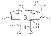
- the structure of the split core of the stator core 32a will be described with reference to FIG. 5 is a view seen from a direction corresponding to the axial direction when assembled into a cylindrical stator core 32a.
- the axial direction is the rotational axis of the rotor 31, that is, the axial direction of the crankshaft 4 when the stator core 32 a is assembled as the electric mechanism unit 3.
- the split iron core 60 has a T-shape and includes one tooth 32c and a back yoke 32b connected to the tooth 32c.
- the back yoke 32b has an arc shape.
- the teeth 32c are provided at a substantially right angle to the back yoke 32b in the center of the back yoke 32b.
- the teeth 32c are provided extending toward the center of the arc shape of the back yoke 32b.
- the back yoke 32b is annular or cylindrical, and the teeth 32c face the center of the ring.
- the tip of the teeth 32 c that is, the portion of the teeth 32 c on the side opposite to the back yoke 32 b is a surface facing the rotor 31.
- the surface has a shape that spreads in a reverse arc shape along the outer peripheral surface of the rotor 31.
- the back yoke 32b constitutes a cylindrical outer peripheral portion of the stator iron core 32a. Therefore, the part which contacts the airtight container 1 mentioned later is the back yoke 32b.
- the split iron core 60 When the split iron core 60 is formed, the thin magnetic steel plates are superposed and caulked in the superposition direction to fix the magnetic steel plates together. 61 is caulking.
- the insulating member 32 f is fixed to the end surface in the axial direction of the split core 60.
- the insulating member 32 f is provided with a protrusion that is engaged with the split iron core 60.
- a hole 62 is provided in the end surface of the split iron core 60 in the axial direction. The protrusion provided on the insulating member 32f is inserted into the hole 62 of the split iron core 60 and locked.
- the split iron core 60 has end faces 63 and 64 of the back yoke 32b in a direction perpendicular to the teeth 32c, that is, in the circumferential direction of the back yoke 32b. After the winding is wound around the teeth 32c, the split core 60 is welded at the end surfaces 63 and 64 of the back yoke 32b to join the split cores 60 together.
- stator core 32a connects a plurality of split cores 60
- segmentation iron core 60 often shifts
- the work of aligning in an annular shape requires very advanced techniques. Therefore, there is a method of winding the stator winding 32d after connecting the split iron core 60 in advance.
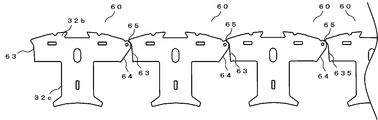
- Fig. 6 shows iron cores that are formed by connecting divided iron cores and aligning them in a line in a chain.
- the split iron core 60 extends a part of the electromagnetic steel sheet constituting the back yoke 32b in the circumferential direction so that it can be overlapped with a part of the electromagnetic steel sheet of the back yoke 32b of the adjacent split iron core.
- the overlapping portion hits a rivet or the like in the stacking direction of the electromagnetic steel sheets and engages so as to be rotatable. Thereby, adjacent division
- the engaging portion becomes the connecting portion 65.
- stator winding 32d When the stator winding 32d is wound, the stator winding 32d is wound around the teeth 32c in a state where the divided cores 60 are aligned in a row as shown in FIG. Thereby, the stator winding 32d can be wound without causing contact or interference with the stator of the winding jig.
- stator core 32a After the stator winding 32d is wound around the teeth 32c, the stator core 32a is rotated about each connecting portion 65 as shown in FIG. 7 to form the split core 60 in an annular shape.
- the last joint surfaces 66A and 66B for closing the ring are joined by welding.
- An insulating member 32 f is attached to the split iron core 60.
- the insulating member 32f is disposed on the end surface of the split iron core 60 in the stacking direction of the electromagnetic steel plates, the insulating member 32f is also disposed on the end surface of the connecting portion in the stacking direction of the electromagnetic steel plates. Therefore, since the insulating member 32f closes the direction in which the rivet is inserted into the connecting portion, it is difficult to join the rivet or the like in the stacking direction of the electromagnetic steel sheets after winding the stator winding 32d. Therefore, it is common to join by welding.
- FIG. 8 shows a state of the stator core 32a in which the divided cores 60 are joined, and is formed in an annular shape.
- An annularly formed stator core 32 a is press-fitted into the hermetic container 1. Thereafter, the stator core 32a is welded to the sealed container 1 and fixed. That is, the stator core 32 a is fixed to the inner wall of the sealed container 1.
- the protrusion is provided in the outer peripheral surface of the outer diameter of the stator core 32a. The protrusion and the inner wall of the sealed container 1 come into contact with each other and are fixed. Therefore, a gap is provided between the inner wall of the sealed container 1 and the outer peripheral surface of the outer diameter of the stator core 32a. Thereby, the influence of the deformation
- Non-uniformity in the rotational speed of the electric mechanism unit 3 causes noise generation and efficiency reduction.
- the stator core 32a has a cross section perpendicular to the axial direction close to a perfect circle and the teeth 32c are aligned at equal intervals.
- the stator core 32a connects the split cores 60 by welding, deformation due to thermal action occurs.
- the stator core 32a is deformed by a load generated by press fitting, welding, shrink fitting, or the like.
- the stator core 32 a receives a tightening load by the sealed container 1.
- stator core 32 a receives a load due to thermal expansion and contraction of the sealed container 1.
- shrink fitting since the high-pressure and high-temperature refrigerant gas passes through the electric mechanism unit 3, the hermetic container 1 and the electric mechanism unit 3 are also subjected to the thermal action, and the stator core 32a receives a load. Due to these loads, the split core 60 tends to move in the radial direction and the circumferential direction, causing distortion and deformation, and the stator core 32a is deformed from a perfect circle.
- the joint 66 is welded, so that it is deformed from a perfect circle by its thermal action. Further, in the stator core 32a in which the divided iron cores are connected in advance, the connecting portion 65 and the joint portion 66 are deformed or distorted due to the difference in rigidity. The connecting portion 65 can move, but the joint portion 66 cannot move. Therefore, if a load is applied to the stator core 32a, the split core 60 tries to move in the radial direction and the circumferential direction, and the stator core 32a starts from a perfect circle. Deform.
- all the joint portions of the split iron cores are connected by a rotatable connecting portion without welding, and the load when the stator core 32a is incorporated in the sealed container 1 in the connecting portion. And a structure that relieves stress. That is, even if the insulating member 32f blocks the direction in which the rivet is inserted into the connecting portion, the connecting portion can be connected. 9, 10, 11, and 12 explain the details of the connecting structure.
- the split iron core 60 is configured by stacking a first type of electromagnetic steel plate 71 and a second type of electromagnetic steel plate 72. That is, it is laminated in the axial direction when the stator core 32a is formed.
- the first type of electromagnetic steel sheet 71 and the second type of electromagnetic steel sheet 72 are T-shaped in a plan view as viewed from the perpendicular direction, that is, the stacking direction with respect to the electromagnetic steel sheet.
- Each of them is composed of a split iron core 60, a part that forms an arcuate back yoke 32b, and a part that forms a tooth 32c provided substantially at a right angle in the center of the back yoke 32b.
- the split iron core 60 has a structure in which first-type electromagnetic steel plates 71 and second-type electromagnetic steel plates 72 are alternately stacked and arranged.
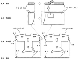
- FIG. 9 shows the overall shape of the first type of electromagnetic steel sheet 71 and also shows an enlarged connection portion of the first type of electromagnetic steel sheet 71.
- the third stage of the fourth stage in FIG. 9 is a plan view of the entire first type of electrical steel sheet 71 as viewed from the direction perpendicular to the electrical steel sheet, and the fourth stage is the first type.
- vertical direction with respect to the electromagnetic steel plate is represented.
- the second level is an enlarged view of the connecting portion of the first type of electrical steel sheet 71, as viewed from the vertical direction with respect to the electrical steel sheet, and the first level is an enlarged part of the second level. Is a cross-sectional view taken along the circumferential direction of the back yoke and perpendicular to the electromagnetic steel sheet.
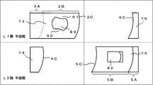
- FIG. 10 shows the overall shape of the second type of electromagnetic steel sheet 72 and also shows an enlarged connection portion of the second type of electromagnetic steel sheet 72.
- FIG. 10 is also similar to FIG. 9, the third of the four stages is a plan view of the entire second-type electromagnetic steel sheet 72 as viewed from the direction perpendicular to the electromagnetic steel sheet.
- FIG. 11 shows a state where the first type of electromagnetic steel plate 71 and the second type of electromagnetic steel plate 72 are stacked, and shows the entire divided iron core.
- FIG. 11 is a plan view of the entire divided iron core as viewed from the vertical direction with respect to the magnetic steel sheet, and the lower part shows the back yoke of the divided iron core in the circumferential direction of the back yoke and in the vertical direction with respect to the magnetic steel sheet.
- disconnected by is represented.
- the cross section represents only one stack of the first type of electromagnetic steel sheet 71 and one second type of electromagnetic steel sheet 72, and the divided iron core includes a plurality of sheets of each electromagnetic steel sheet. , Stacked and configured.
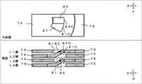
- FIG. 12 shows a connecting portion of the first-type electromagnetic steel sheet 71 and the second-type electromagnetic steel sheet 72 in any continuous four layers L1 to L4 of the split iron core.
- FIG. 12 shows a connecting portion of the first-type electromagnetic steel sheet 71 and the second-type electromagnetic steel sheet 72 in any continuous four layers L1 to L4 of the split iron core.
- the number of laminations of the first type of electrical steel sheet 71 and the second type of electrical steel sheet 72 is preferably more than four, but here, for convenience of explanation, only four layers L1 to L4 are shown. . 9, 10, 11, and 12 show the first type of electromagnetic steel plate 71, the second type of electromagnetic steel plate 72, and the laminate thereof of the adjacent split cores.
- the left iron steel plates (71, 72) are laminated and the left divided iron core is formed on the left side, and the first divided iron core 60A and the right electromagnetic steel plates (71, 72) are laminated on the right side.
- the divided iron core will be described as a second divided iron core 60B.
- the right-side enlarged portion of the first type of electromagnetic steel plate 71 will be described as an electromagnetic steel plate 73
- the right-side enlarged portion of the second type of electromagnetic steel plate 72 will be described as an electromagnetic steel plate 74.
- the left side enlarged portion of the second type electromagnetic steel plate 72 will be described as the electromagnetic steel plate 75
- the left side enlarged portion of the first type electromagnetic steel plate 71 will be described as the electromagnetic steel plate 76.
- the component arranged on the left side of the enlarged view is a partial enlarged view of the right end of the back yoke 32b of the first divided iron core 60A, and the component arranged on the right side of the enlarged view is the second divided iron core. It is the elements on larger scale of the left end part of the back yoke 32b of 60B.
- segmentation iron core 60B are distinction for convenience of explanation, and are the adjacent division
- the electromagnetic steel plate 73 has a laminated portion 3A that overlaps the electromagnetic steel plate 74 and a protruding portion 3B that protrudes outward in the circumferential direction of the back yoke 32b from the electromagnetic steel plate 74.
- the hole 81 is provided in the protruding portion 3B that protrudes.
- the hole 81 of the electromagnetic steel sheet 73 has a fan-shaped cross section perpendicular to the electromagnetic steel sheet 73 in the vertical direction.
- the inner wall 81A on the inner peripheral side of the arc-shaped back yoke 32b of the hole 81 and the inner wall 81B on the outer peripheral side of the arc-shaped back yoke 32b of the hole 81 constitute a fan-shaped linear portion. That is, it is a linear surface in a plan view as viewed from the vertical direction with respect to the electromagnetic steel sheet 73.
- the inner wall 81 ⁇ / b> C on the end 3 ⁇ / b> C side of the hole 81 forms a fan-shaped arc portion.
- the end 3C side is the side opposite to the side on which the electromagnetic steel plates 74 are stacked.
- the inner wall on the side opposite to the end 3 ⁇ / b> C of the hole 81, that is, on the electromagnetic steel sheet 74 side may have an arbitrary shape.
- the inner wall is comprised by the circular arc-shaped surface by the planar view seen from the perpendicular direction with respect to the electromagnetic steel plate 73.
- the electromagnetic steel plate 75 has a laminated portion 5A that overlaps the electromagnetic steel plate 76 and a protruding portion 5B that protrudes outward in the circumferential direction of the back yoke 32b from the electromagnetic steel plate 76.
- the protrusion 82 is provided on the protruding portion 5B.
- the protrusion 82 of the electromagnetic steel sheet 75 protrudes in a direction in which the electromagnetic steel sheets are stacked, that is, in a direction perpendicular to the electromagnetic steel sheet 75 and has elasticity.
- the protrusion 82 has a shape in which the electromagnetic steel plate 76 side protrudes from the electromagnetic steel plate 74 side. That is, there is an inclination in the direction of the electromagnetic steel plate 76 from the electromagnetic steel plate 74 side.
- An outer peripheral surface 82A on the inner peripheral side of the arc-shaped back yoke 32b of the protrusion 82 and an outer peripheral surface 82B on the outer peripheral side of the arc-shaped back yoke 32b of the protrusion 82 are opposed to each other and are substantially parallel surfaces.
- the outer peripheral surface 82 ⁇ / b> C on the side where the magnetic steel sheets 76 of the protrusions 82 are stacked has an arc shape in a plan view as viewed from the vertical direction with respect to the third magnetic steel sheet 75.
- the side on which the electromagnetic steel plates 76 are stacked is the side on which the teeth 32c are disposed. Therefore, the outer peripheral surface 82C of the protrusion 82 is the outer peripheral surface on the side where the hole 81 is disposed, and the inner wall 81C of the hole 81 is the inner wall on the opposite side to the side where the protrusion 82 is disposed.
- the arc shape of the outer peripheral surface 82C of the protrusion 82 is an arc shape having the same radius and the same shape as the inner wall 81C of the hole 81. That is, the arc-shaped radius of the outer peripheral surface 82 ⁇ / b> C of the protrusion 82 matches the arc-shaped radius of the inner wall 81 ⁇ / b> C of the hole 81.
- the protrusion 82 may be formed by an arbitrary method, but in the present embodiment, the protrusion 82 is formed by cutting and raising a part of the electromagnetic steel sheet 75.
- the split iron core 60A includes the hole 81 at one end of the back yoke 32b.
- the split iron core 60B includes a protrusion 82 at one end of the back yoke 32b. Since the divided iron cores 60A and 60B are distinguished for convenience of explanation, the divided iron cores 60A and 60B, that is, the divided iron core 60 includes a hole 81 at one end of the back yoke 32b, and a protrusion 82 at the other end. It is the structure provided with.
- the projections 82 of the electromagnetic steel plate 72 are fitted in the holes 81 of the electromagnetic steel plate 71.
- the divided iron cores 60 are engaged with each other by the same number of protrusions 82 as the number of the electromagnetic steel plates 72. Therefore, the greater the number of protrusions 82, the stronger the engaging force between the divided iron cores 60.
- a connecting portion between the split iron core 60A and the split iron core 60B is configured.
- the shape of the hole 81 and the shape of the protrusion 82 will be described. If the fan-shaped center of the hole 81 is P, the center P is closer to the electromagnetic steel sheet 74 than the hole 81.
- An inner wall 81 ⁇ / b> C of the hole 81 is formed in an arc shape centered on P.
- the outer peripheral surface 82 ⁇ / b> C of the protrusion 82 is formed in an arc shape drawn with the same radius as the center P to the inner wall 81 ⁇ / b> C of the hole 81.
- the outer peripheral surface 82 ⁇ / b> C of the protrusion 82 is arranged in an arc shape centered on P. That is, the outer peripheral surface 82C of the protrusion 82 and the inner wall 81C of the hole 81 are configured to be in surface contact.
- the center P is the center when the split iron core 60 is rotated.
- the end surface of the electromagnetic steel plate 73 on the side of the electromagnetic steel plate 76, the end surface of the electromagnetic steel plate 74 on the side of the electromagnetic steel plate 75, the end surface of the electromagnetic steel plate 75, the end surface of the electromagnetic steel plate 74, The end surface on the electromagnetic steel sheet 73 side is also preferably configured in an arc shape centered on P.
- Y represents the radial direction when the split cores 60A and 60B formed the stator core 32a
- Z represents the split core.
- 60A and 60B represent axial directions when the stator core 32a is formed.
- the procedure for connecting the split iron cores 60A and 60B will be described.
- the electromagnetic steel plate 75 and the electromagnetic steel plate 76 are moved toward the electromagnetic steel plate 73 and the electromagnetic steel plate 74. That is, the split iron core 60B is moved toward the split iron core 60A.
- the electromagnetic steel plate 73 of the split iron core 60A and the electromagnetic steel plate 76 of the split iron core 60B are moved so as to be in the same layer.
- the electromagnetic steel plate 74 of the split iron core 60A and the electromagnetic steel plate 75 of the split iron core 60B are moved so as to be in the same layer.
- the electromagnetic steel sheet 75 of the layer L2 is inserted into a gap generated under the electromagnetic steel sheet 73 of the upper layer L1.
- the protrusion 82 of the electromagnetic steel plate 75 of the layer L2 is opposite to the side where the axial protrusion 82 protrudes from the circumferential end of the electromagnetic steel plate 73 of the layer L1. Is elastically deformed.
- the protrusion 82 is gradually crushed by the circumferential end of the electromagnetic steel plate 73 of the layer L1 that contacts the inclined surface of the protrusion 82.
- the circumferential end portion of the electromagnetic steel plate 73 corresponds to the end 3C of the electromagnetic steel plate 73 of the layer L1 shown in FIG.
- the electromagnetic steel plate 75 of the layer L4 is also inserted into a gap generated under the electromagnetic steel plate 73 of the upper layer L3. Therefore, the electromagnetic steel plate 73 of the layer L3 is inserted into a gap generated under the electromagnetic steel plate 75 of the upper layer L2.
- the electromagnetic steel sheet 75 can be easily inserted as compared with other methods such as press fitting.
- the hole 81 and the protrusion 82 are engaged, and the divided iron core 60A and the divided iron core 60B are connected.
- the connecting portion 65 is configured by the hole 81 and the protrusion 82.
- the connecting portion 65 is engaged in a state where the outer peripheral surface 82C of the protrusion 82 is in contact with the inner wall 81C of the hole 81 and in a state where the outer peripheral surface 82B of the protrusion 82 is in contact with the inner wall 81B of the hole 81. Yes.
- the other divided iron cores 60 can be connected in order to form a chain-connected iron core.
- a contact force that is, a drag force acts between the outer peripheral surface 82C of the protrusion 82 and the inner wall 81C of the hole 81, and the divided cores 60A and 60B are not separated.
- the outer peripheral surface 82C of the protrusion 82 and the inner wall 81C of the hole 81 have an arc shape with the same center and the same radius, a large contact force acts on the surface contact between the surfaces. Further, because of the surface contact, even if a larger contact force is applied, the load is distributed over the entire surface, and the engaged state can be maintained without damaging the protrusion 82 and the hole 81.
- the protrusion 82 and the hole 81 When there is a point contact between the protrusion 82 and the hole 81, the load concentrates on the contact point, and the protrusion 82 and the hole 81 may be damaged.
- the vertex of the square shape and the arc-shaped surface of the inner wall 81C of the hole 81 are in point contact. If a large contact force is applied, the protrusion 82 or the hole 81 may be damaged. However, in this embodiment, surface contact prevents this.
- the procedure for refracting the iron core connected in a chain shape from the connecting portion will be described. Specifically, the split iron core 60B is moved toward the teeth of the split iron core 60A around the connecting portion 65.
- the outer peripheral surface 82A of the protrusion 82 and the inner wall 81A of the hole 81 are stopped in contact with each other.
- the divided cores 60 ⁇ / b> A and 60 ⁇ / b> B connected to each other can rotate around the point P of the connecting portion 65 and be refracted.
- the split iron core 60B can be rotated without deviating from the orbit of rotation.
- the end 6C of the electromagnetic steel plate 76 moves along the end 3C of the electromagnetic steel plate 73, and the end 5C of the electromagnetic steel plate 75 is the electromagnetic steel plate. It moves along the end 4C of 74.
- the contact force between the end 6C of the electromagnetic steel plate 76 and the end 3C of the electromagnetic steel plate 73, the end 5C of the electromagnetic steel plate 75, and the end of the electromagnetic steel plate 74 Since the contact force with 4C is applied and rotated while being used, the divided iron core 60 can be rotated without deviating from the rotation trajectory.
- the split iron core 60 rotates around the point P of the connecting portion 65, the abutting surfaces are brought into contact with each other or pressed to stop the rotation.
- the first type of magnetic steel sheet 71 has butted surfaces 83 and 84 at both ends in the circumferential direction of the back yoke as shown in FIG.
- the second type of electromagnetic steel sheet 72 has butt surfaces 85 and 86 at both ends in the circumferential direction of the back yoke.
- the split iron core 60 when the split iron core 60 is rotated, the outer peripheral surface 82A of the protrusion 82 and the inner wall 81A of the hole 81 are in contact with each other, the butting surface 83 of the electromagnetic steel plate 71 of one split iron core 60 and the other split iron core 60.
- the abutting surface 84 of the electromagnetic steel plate 71 is contacted or pressed, and the abutting surface 85 of the electromagnetic steel plate 72 of one divided iron core 60 and the abutting surface 86 of the electromagnetic steel plate 72 of the other divided iron core 60 are contacted or pressed. Therefore, the rotation is stopped.
- annular stator core 32a can be formed without narrowing the magnetic path of the magnetic flux passing through the back yoke 32b by ensuring that the butted surfaces come into contact with each other. Since the stator core 32a does not narrow the magnetic path of the back yoke 32b, the stator core 32a can be configured without reducing the efficiency of the electric mechanism section 3.
- adjacent divided iron cores can be connected in a chain shape, and the connected iron cores can be refracted from the connecting portion.
- the outer peripheral surface 82C of the protrusion 82 and the hole 81 are formed, as in the chain-connected state. Due to the surface contact between the inner wall 81C and the inner wall 81C, the contact force between the projection 82 and the inner wall of the hole 81 works, and the split cores 60A and 60B are not separated.
- the protrusion 82 and the hole 81 are in surface contact, the load as the contact force is dispersed, and the engaged state can be maintained without damaging the protrusion 82 or the hole 81. Even if the divided iron cores 60A and 60B are pushed in the circumferential direction, the butted surfaces 83 and 84, 85 and 86 are restrained from each other, and the projection 82 does not come out of the hole 81. That is, the split iron cores 60A and 60B are not disconnected.
- the joint surfaces 66A and 66B that finally close the ring are welded, but in the present embodiment, the projection 82 and the hole 81 are also applied to the portion that finally closes the ring, in the same manner as other connecting portions. , And the projection 82 is fitted into the hole 81 and engaged.
- the adjacent divided cores 60 can be connected to each other even when the insulating member 32f is attached to the divided cores 60. This is because, by inserting the electromagnetic steel sheet 75 into the gap generated under the upper electromagnetic steel sheet 73, the protrusion 82 fits into the hole 81, so that a riveting or caulking is performed in the lamination direction of the electromagnetic steel sheets. You can connect without having to go. Even if the insulating member 32f covers the connecting portion, the connection of the split core 60 is not hindered.
- the stator core 32a can have a predetermined annular shape. Even if a load is applied to the connected split cores 60 during assembly, the connected split cores 60 are not separated from each other.
- the outer peripheral surface 82 ⁇ / b> C of the protrusion 82 and the inner wall 81 ⁇ / b> C of the hole 81 are in surface contact with each other, and a contact force acts to prevent the divided iron cores 60 from being separated from each other.
- the protrusion 82 and the hole 81 are in surface contact, the load as a contact force is dispersed, and the engagement state can be maintained without damaging the protrusion 82 or the hole 81.
- the butted surfaces stop each other, and the protrusion 82 does not come out of the hole 81, so that the engaged state can be maintained. Further, even if a force that shifts the connected divided cores 60 in the radial direction is applied, the contact force between the outer peripheral surface 82A of the protrusion 82 and the inner wall 81A of the hole 81 does not shift in the radial direction. . Also in this case, due to the surface contact between the protrusion 82 and the hole 81, the load is distributed over the entire surface, and the engaged state can be maintained without damaging the protrusion 82 and the hole 81.
- the joint that closes the ring at the end can be made into a ring without welding, workability is improved. Furthermore, since all the connecting portions of the stator core 32a can have the same structure, the rigidity of the ring of the stator core 32a can be made uniform. Since the rigidity of the ring of the stator core 32a can be made uniform, the stator core 32a is also resistant to strain with respect to the load applied to the stator core 32a.
- stator core 32a when the stator core 32a is assembled in an annular shape, when a load that deforms from the ring shape is applied, the load is reduced by the rotating structure of the connecting portion, the restraining structure, and the restraining structure of the butting surface. While dispersing, it restrains the circumferential and radial shifts of the split iron core. For example, even if the component expands and contracts due to thermal action, the rotation structure and restraining structure of the connecting portion and the restraining structure of the butting surface generate a repulsive force against distortion, and the annular shape of the stator core 32a Try to maintain. Thereby, even if it press-fits and welds to the airtight container 1, roundness can be maintained.
- stator core 32a when the stator core 32a is incorporated in the hermetic container 1 and operated as a compressor, the stator core 32a is distorted by the heat action of the refrigerant gas even if it is used so that high-pressure and high-temperature refrigerant gas passes. Absorbs and maintains roundness.
- the stator core of the present embodiment when the stator core of the present embodiment is incorporated in a sealed container, strain can be absorbed and high roundness can be maintained. That is, it is possible to obtain an electric mechanism section that reduces the load and stress when incorporated in the sealed container and suppresses deformation of the stator and suppresses uneven rotation. And the compressor which suppressed the noise and the efficiency fall is obtained by using the electric mechanism part for a compressor. In addition, even when operated as a compressor for refrigerant compression, the influence of the heat action of the high-pressure and high-temperature refrigerant gas can be suppressed, and a compressor that suppresses noise and efficiency reduction can be obtained.
- stator of a compressor motor it is possible to manufacture without changing the working environment, as before, by attaching an insulating member to a split iron core, winding a fixed winding, and then assembling in a ring shape. it can.
- the split core prevents and suppresses the deviation in the circumferential direction and the radial direction, so there is a gap between the butted surfaces of the back yoke of the split core. Without being born, the abutting surfaces can be reliably in contact with each other and kept in an annular shape. As a result, the magnetic path passing through the back yoke is narrowed, and an efficient compressor can be obtained without reducing the efficiency of the electric mechanism.
- connection parts of the stator cores can have the same structure, so that the rigidity of the rings of the stator cores can be made uniform. Since the rigidity of the stator core ring can be made uniform, the stator core is also resistant to strain with respect to the load applied to the stator core. Furthermore, workability is improved by not performing welding.
- the laminated electrical steel sheets do not necessarily have the protrusions 82 or the holes 81.
- a magnetic steel plate that does not have the protrusions 82 and the holes 81 may be used as the magnetic steel plates that are being superposed.
- the inner wall of the hole 81 on the electromagnetic steel plate 74 side is also an arc-shaped surface in a plan view as viewed from the perpendicular direction to the electromagnetic steel plate 73, it is not necessarily required to have an arc shape.
- it may be linear in a plan view as viewed from the direction perpendicular to the direction in which the electromagnetic steel sheets are stacked, that is, the electromagnetic steel sheets.
- the straight inner wall only needs to be composed of at least two sides perpendicular to the inner wall 81A of the hole 81 and the inner wall 81B of the hole 81.
- the protrusion 82 and the inner wall on the center P side of the hole 81 do not hinder the protrusion 82 from fitting into the hole 81. Further, when the divided iron core 60B is rotated, the protrusion 82 and the inner wall on the center P side of the hole 81 do not hinder the movement of the protrusion 82 in the hole 81.
- the inner wall on the center P side of the hole 81 has an arc shape, whereas the inner wall orthogonal to the inner wall 81A of the hole 81 and the inner wall 81B of the hole 81 makes the hole 81 before rotating the divided iron core 60B.
- the position of the protrusion 82 with respect to the hole 82 and the position of the protrusion 82 with respect to the hole 81 after rotating the divided iron core 60B are easily determined. As a result, the engaged state is stabilized, and the connection is difficult to be disconnected.
- Embodiment 2 the example in which the hole 81 of the electromagnetic steel sheet 73 has a fan shape in a plan view as viewed from the direction perpendicular to the electromagnetic steel sheet, that is, the direction in which the electromagnetic steel sheets are laminated has been described.
- the fan-shaped center P is closer to the electromagnetic steel plate 74 than the hole 81
- the point P is the center of rotation of the divided iron core 60B.
- the hole in the electromagnetic steel sheet 73 does not necessarily have a fan shape, and the center of rotation does not have to be closer to the electromagnetic steel sheet 74 than the hole 81. A case where the center of rotation is at the same position as the hole 81 will be described.
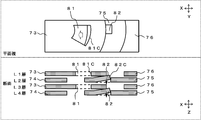
- FIG. 19 is an enlarged view of the connecting portion of the split iron core 60, and is a plan view of the electromagnetic steel sheet viewed from the vertical direction.
- FIG. 20 is an enlarged view of the hole portion of FIG. Except that the holes in the electromagnetic steel sheet 73 are made substantially circular and the protrusions are matched to the shape, the same parts are denoted by the same reference numerals.
- the hole 87 of the electromagnetic steel plate 73 has a substantially circular cross section perpendicular to the electromagnetic steel plate 73 and has two convex portions 90 and 91 protruding toward the center direction on the inner wall thereof.
- the convex portions 90 and 91 are disposed so as to face each other.
- the convex parts 90 and 91 are the same shape, and the cross section orthogonal to the perpendicular direction with respect to the electromagnetic steel sheet 73 is a triangular shape composed of two straight sides.
- the convex part 90 is comprised from the outer peripheral surface 90B which comprises one side by the side of the electromagnetic steel plate 74, and the outer peripheral surface 90A which comprises one side by the side of the electromagnetic steel plate 76.
- the convex part 91 is comprised from 91 A of outer peripheral surfaces which comprise 1 side by the side of the electromagnetic steel plate 74, and 91 B of outer peripheral surfaces which comprise 1 side by the side of the electromagnetic steel plate 76.
- the outer peripheral surface 90A of the convex portion 90 and the outer peripheral surface 91A of the convex portion 91 are arranged in parallel.
- the outer peripheral surface 90B of the convex part 90 and the outer peripheral surface 91B of the convex part 91 are arranged in parallel.
- the inner wall 87C of the hole 87 other than the convex portions 90 and 91 is a part of a circular shape, that is, an arc shape.
- the protrusion 82 of the electromagnetic steel sheet 75 is the same as that of the first embodiment, and protrudes in the direction in which the electromagnetic steel sheets are stacked, that is, in the direction perpendicular to the electromagnetic steel sheet 75. It has elasticity, is inclined in the direction from the electromagnetic steel sheet 74 to the electromagnetic steel sheet 76, the outer peripheral surface of the arc-shaped back yoke 32b of the protrusion 82, and the outer periphery of the arc-shaped back yoke 32b of the protrusion 82
- the outer peripheral surface is a plane that is substantially parallel to each other, and that the outer peripheral surface 82C of the electromagnetic steel sheet 76 of the protrusion 82 has a circular arc shape in a cross section perpendicular to the electromagnetic steel sheet 75. This is the same as the protrusion 82 of the first embodiment.
- the method for forming the protrusions 82 may be formed by any method, but it can be formed by cutting and raising a part of the electromagnetic steel sheet 72 as in
- the arc shape of the outer peripheral surface 82 ⁇ / b> C of the protrusion 82 is an arc shape having the same radius as the radius of the hole 87.
- the outer peripheral surface 82 ⁇ / b> C of the protrusion 82 is arranged in an arc shape centering on the center of the hole 87. That is, the outer peripheral surface 82C of the protrusion 82 and the inner wall 87C of the hole 87 have an arc shape or a circular shape with the same center and the same radius, and are configured such that the surfaces are in surface contact.
- the center of the hole 87 is the center P when the split iron core 60B is rotated.
- the procedure for connecting the split iron cores 60 and the procedure for bending the split iron cores 60 from the connecting portion and forming them in an annular shape are the same as in the first embodiment.
- the electromagnetic steel sheet 75 is inserted into a gap generated under the electromagnetic steel sheet 73 of the upper layer.
- the protrusion 82 is fitted into the hole 87 and engaged.
- the protrusion 82 and the hole 87 are in a state where the outer peripheral surface 82C of the protrusion 82 and the inner wall 87C of the hole 87 are in contact, and in a state where the outer peripheral surface 82A of the protrusion 82 and the outer peripheral surface 90A of the convex portion 90 of the hole 87 are in contact.
- the outer peripheral surface 82B of the protrusion 82 and the outer peripheral surface 91A of the convex portion 91 of the hole 87 are engaged with each other.
- the split core 60A and the split core 60B are connected, and the connecting portion 65 is also configured.
- the split iron core 60B is moved toward the B teeth of the split iron core 60A.
- the outer peripheral surface 82C of the protrusion 82 moves along the inner wall 87C of the hole 87, whereby the protrusion 87 is moved.
- the outer peripheral surface 82A of the protrusion 82 and the outer peripheral surface 90B of the convex portion 90 of the hole 87 are in contact with each other, and the outer peripheral surface 82B of the protrusion 82 and the outer peripheral surface 91B of the convex portion 91 of the hole 87 are in contact with each other.
- the connecting portion 65 rotates around the center P of the hole 89, and the protrusion 88 rotates in the hole 89.
- the split iron core 60B can be rotated without deviating from the orbit of rotation.
- the hole 87 is a hole provided with the convex portions 90 and 91, when the projection 82 is fitted, the stopping position is determined. As a result, even if the connecting portion of the split iron core is covered with an insulating member and the connecting portion is not visible, the hole and the protrusion are engaged because the stop position is determined by surface contact. It is easy to grasp the engagement position and state during operation.
- the joint that finally closes the ring can be formed into a ring shape without welding. Therefore, the rigidity of the ring of the stator core can be made uniform, and the stator core is also resistant to strain with respect to the load applied to the stator core. Furthermore, workability is improved by not performing welding.
Landscapes
- Engineering & Computer Science (AREA)
- Power Engineering (AREA)
- Applications Or Details Of Rotary Compressors (AREA)
- Iron Core Of Rotating Electric Machines (AREA)
- Compressor (AREA)
Abstract
L'invention concerne des noyaux de stator dans lesquels des noyaux séparés ayant des sections de connexion rotatives sont reliés via les sections de connexion de manière à former une forme cylindrique, dans lesquels les noyaux séparés (60, 60A, 60B) comportent chacun une protubérance en forme d'arc disposée sur un bord d'une culasse arrière (32b) dans la direction circonférentielle sur un côté dent (32C), et un trou en forme d'arc (81) formé sur l'autre bord de la culasse arrière (32b) dans la direction circonférentielle sur le côté opposé au côté où est positionnée la protubérance (82). Les sections de connexion sont configurées de telle sorte que la protubérance (82) d'un noyau divisé adjacent (60, 60A, 60B) s'adapte dans le trou (81) d'un autre noyau divisé (60, 60A, 60B), et que la surface périphérique externe en forme d'arc (82C) de la protubérance (82) vienne en contact et en prise avec la paroi interne en forme d'arc (81C) du trou (81).
Priority Applications (3)
| Application Number | Priority Date | Filing Date | Title |
|---|---|---|---|
| PCT/JP2016/053013 WO2017134740A1 (fr) | 2016-02-02 | 2016-02-02 | Stator et compresseur |
| JP2017564996A JP6504271B2 (ja) | 2016-02-02 | 2016-02-02 | 固定子および圧縮機 |
| CN201680080412.8A CN108604835B (zh) | 2016-02-02 | 2016-02-02 | 定子及压缩机 |
Applications Claiming Priority (1)
| Application Number | Priority Date | Filing Date | Title |
|---|---|---|---|
| PCT/JP2016/053013 WO2017134740A1 (fr) | 2016-02-02 | 2016-02-02 | Stator et compresseur |
Publications (1)
| Publication Number | Publication Date |
|---|---|
| WO2017134740A1 true WO2017134740A1 (fr) | 2017-08-10 |
Family
ID=59499475
Family Applications (1)
| Application Number | Title | Priority Date | Filing Date |
|---|---|---|---|
| PCT/JP2016/053013 Ceased WO2017134740A1 (fr) | 2016-02-02 | 2016-02-02 | Stator et compresseur |
Country Status (3)
| Country | Link |
|---|---|
| JP (1) | JP6504271B2 (fr) |
| CN (1) | CN108604835B (fr) |
| WO (1) | WO2017134740A1 (fr) |
Cited By (5)
| Publication number | Priority date | Publication date | Assignee | Title |
|---|---|---|---|---|
| CN111183568A (zh) * | 2017-10-12 | 2020-05-19 | 大金工业株式会社 | 定子、马达和压缩机 |
| JP2021523671A (ja) * | 2018-07-27 | 2021-09-02 | 広東美芝制冷設備有限公司 | 永久磁石モータ、圧縮機及び空気調和機 |
| JPWO2021009862A1 (ja) * | 2019-07-17 | 2021-11-18 | 三菱電機株式会社 | ステータ、モータ、圧縮機、及び空気調和機 |
| WO2021255830A1 (fr) * | 2020-06-16 | 2021-12-23 | 三菱電機株式会社 | Machine électrique tournante et procédé de fabrication d'une machine électrique tournante |
| JPWO2021260814A1 (fr) * | 2020-06-24 | 2021-12-30 |
Families Citing this family (6)
| Publication number | Priority date | Publication date | Assignee | Title |
|---|---|---|---|---|
| JP6739497B2 (ja) * | 2018-11-06 | 2020-08-12 | 三菱電機株式会社 | 回転電機の電機子 |
| DE212019000130U1 (de) | 2019-08-08 | 2020-06-03 | Guangzhou Trayi Precision Machinery Co., Ltd. | Ölfüll- und Lockerungssystem für einen Motorstator-Eisenkern |
| DE212019000128U1 (de) | 2019-08-08 | 2020-06-03 | Guangzhou Trayi Precision Machinery Co., Ltd. | Lockerungsmechanismus für einen Motorstator-Eisenkern |
| DE212019000125U1 (de) | 2019-08-08 | 2020-05-26 | Guangzhou Trayi Precision Machinery Co., Ltd. | Phasenerfassungsmechanismus für einen Motorstator-Eisenkern |
| CN115136454A (zh) * | 2020-02-19 | 2022-09-30 | 三菱电机株式会社 | 定子、旋转电机以及压缩机 |
| CN113595273A (zh) * | 2021-08-18 | 2021-11-02 | 珠海格力节能环保制冷技术研究中心有限公司 | 一种电机及其装配方法 |
Citations (4)
| Publication number | Priority date | Publication date | Assignee | Title |
|---|---|---|---|---|
| JP2001136700A (ja) * | 1999-11-02 | 2001-05-18 | Mitsubishi Electric Corp | 固定子および固定子の製造方法 |
| JP2004274914A (ja) * | 2003-03-10 | 2004-09-30 | Asmo Co Ltd | 回転電機のコア |
| JP2009118676A (ja) * | 2007-11-08 | 2009-05-28 | Hitachi Koki Co Ltd | 電動工具 |
| WO2014192076A1 (fr) * | 2013-05-28 | 2014-12-04 | 三菱電機株式会社 | Noyau de fer de machine électrique rotative |
Family Cites Families (3)
| Publication number | Priority date | Publication date | Assignee | Title |
|---|---|---|---|---|
| CN1249878C (zh) * | 1998-06-30 | 2006-04-05 | 三菱电机株式会社 | 铁芯组件及其制造方法 |
| JP3943338B2 (ja) * | 2001-02-02 | 2007-07-11 | 三菱電機株式会社 | 鉄心のコア部材 |
| WO2006120975A1 (fr) * | 2005-05-06 | 2006-11-16 | Mitsuba Corporation | Moteur, machine electrique rotative et son stator, et procede pour fabriquer le stator |
-
2016
- 2016-02-02 WO PCT/JP2016/053013 patent/WO2017134740A1/fr not_active Ceased
- 2016-02-02 CN CN201680080412.8A patent/CN108604835B/zh not_active Expired - Fee Related
- 2016-02-02 JP JP2017564996A patent/JP6504271B2/ja not_active Expired - Fee Related
Patent Citations (4)
| Publication number | Priority date | Publication date | Assignee | Title |
|---|---|---|---|---|
| JP2001136700A (ja) * | 1999-11-02 | 2001-05-18 | Mitsubishi Electric Corp | 固定子および固定子の製造方法 |
| JP2004274914A (ja) * | 2003-03-10 | 2004-09-30 | Asmo Co Ltd | 回転電機のコア |
| JP2009118676A (ja) * | 2007-11-08 | 2009-05-28 | Hitachi Koki Co Ltd | 電動工具 |
| WO2014192076A1 (fr) * | 2013-05-28 | 2014-12-04 | 三菱電機株式会社 | Noyau de fer de machine électrique rotative |
Cited By (12)
| Publication number | Priority date | Publication date | Assignee | Title |
|---|---|---|---|---|
| CN111183568A (zh) * | 2017-10-12 | 2020-05-19 | 大金工业株式会社 | 定子、马达和压缩机 |
| EP3678285A4 (fr) * | 2017-10-12 | 2020-11-11 | Daikin Industries, Ltd. | Stator, moteur et compresseur |
| JP2021523671A (ja) * | 2018-07-27 | 2021-09-02 | 広東美芝制冷設備有限公司 | 永久磁石モータ、圧縮機及び空気調和機 |
| US11996733B2 (en) | 2018-07-27 | 2024-05-28 | Guangdong Meizhi Compressor Co., Ltd. | Permanent magnet motor, compressor and air conditioner |
| JPWO2021009862A1 (ja) * | 2019-07-17 | 2021-11-18 | 三菱電機株式会社 | ステータ、モータ、圧縮機、及び空気調和機 |
| JP7607563B2 (ja) | 2019-07-17 | 2024-12-27 | 三菱電機株式会社 | ステータ、モータ、圧縮機、及び空気調和機 |
| WO2021255830A1 (fr) * | 2020-06-16 | 2021-12-23 | 三菱電機株式会社 | Machine électrique tournante et procédé de fabrication d'une machine électrique tournante |
| JPWO2021260814A1 (fr) * | 2020-06-24 | 2021-12-30 | ||
| WO2021260814A1 (fr) * | 2020-06-24 | 2021-12-30 | 三菱電機株式会社 | Stator, moteur électrique, compresseur, dispositif à cycle de réfrigération et climatiseur |
| JP7286019B2 (ja) | 2020-06-24 | 2023-06-02 | 三菱電機株式会社 | 固定子、電動機、圧縮機、冷凍サイクル装置及び空気調和装置 |
| JP2023103425A (ja) * | 2020-06-24 | 2023-07-26 | 三菱電機株式会社 | 固定子、電動機、圧縮機、冷凍サイクル装置及び空気調和装置 |
| JP7471493B2 (ja) | 2020-06-24 | 2024-04-19 | 三菱電機株式会社 | 固定子、電動機、圧縮機、冷凍サイクル装置及び空気調和装置 |
Also Published As
| Publication number | Publication date |
|---|---|
| JPWO2017134740A1 (ja) | 2018-04-19 |
| CN108604835A (zh) | 2018-09-28 |
| CN108604835B (zh) | 2020-10-02 |
| JP6504271B2 (ja) | 2019-04-24 |
Similar Documents
| Publication | Publication Date | Title |
|---|---|---|
| JP6504271B2 (ja) | 固定子および圧縮機 | |
| KR101892405B1 (ko) | 압축기 및 압축기 제조 방법 | |
| JPWO2018138864A1 (ja) | 固定子、電動機、圧縮機、および冷凍空調装置 | |
| EP3678285B1 (fr) | Stator, moteur et compresseur | |
| US20120301334A1 (en) | Compressor and Refrigerating Cycle Apparatus | |
| CN105545746B (zh) | 压缩机制造装置以及压缩机制造方法 | |
| JP2010279126A (ja) | 電動機固定子鉄心、電動機、密閉型圧縮機、冷凍サイクル装置 | |
| JP5708267B2 (ja) | 回転電気機械及びそれを用いた圧縮機 | |
| JP7511770B2 (ja) | 固定子、回転電機、圧縮機、及び冷凍サイクル装置 | |
| CN108475963A (zh) | 密闭式压缩机以及制冷循环装置 | |
| WO2020170418A1 (fr) | Moteur, compresseur et dispositif de climatisation | |
| WO2020166430A1 (fr) | Compresseur | |
| JP6714907B2 (ja) | 回転子、電動機、密閉型圧縮機および回転子の製造方法 | |
| CN206302218U (zh) | 定子铁心、压缩机以及冷冻循环装置 | |
| JP6556342B2 (ja) | 固定子、モータ、圧縮機および冷凍サイクル装置 | |
| JP2023070660A (ja) | 回転電気機械、圧縮機、および冷凍装置 | |
| JP2008101558A (ja) | 密閉型圧縮機 | |
| CN205105013U (zh) | 压缩机 | |
| JP6972658B2 (ja) | モータ及び圧縮機 | |
| JP7693102B2 (ja) | 電動機の回転子、電動機、圧縮機、及び冷凍サイクル装置 | |
| JP6590904B2 (ja) | 圧縮機製造装置及び圧縮機製造方法 | |
| WO2024195052A1 (fr) | Stator, moteur électrique, compresseur, dispositif à cycle de réfrigération et procédé d'enroulement | |
| WO2023248404A1 (fr) | Procédé de production de stator, stator de moteur électrique, moteur électrique, compresseur hermétique et dispositif à cycle de réfrigération | |
| WO2022180717A1 (fr) | Moteur électrique, compresseur et dispositif à cycle de réfrigération | |
| WO2023112078A1 (fr) | Stator, moteur, compresseur et dispositif à cycle de réfrigération |
Legal Events
| Date | Code | Title | Description |
|---|---|---|---|
| 121 | Ep: the epo has been informed by wipo that ep was designated in this application |
Ref document number: 16889230 Country of ref document: EP Kind code of ref document: A1 |
|
| ENP | Entry into the national phase |
Ref document number: 2017564996 Country of ref document: JP Kind code of ref document: A |
|
| NENP | Non-entry into the national phase |
Ref country code: DE |
|
| 122 | Ep: pct application non-entry in european phase |
Ref document number: 16889230 Country of ref document: EP Kind code of ref document: A1 |