WO2021255830A1 - Machine électrique tournante et procédé de fabrication d'une machine électrique tournante - Google Patents
Machine électrique tournante et procédé de fabrication d'une machine électrique tournante Download PDFInfo
- Publication number
- WO2021255830A1 WO2021255830A1 PCT/JP2020/023612 JP2020023612W WO2021255830A1 WO 2021255830 A1 WO2021255830 A1 WO 2021255830A1 JP 2020023612 W JP2020023612 W JP 2020023612W WO 2021255830 A1 WO2021255830 A1 WO 2021255830A1
- Authority
- WO
- WIPO (PCT)
- Prior art keywords
- stator core
- housing
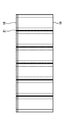
- electric machine
- protrusions
- rotary electric
- Prior art date
- Legal status (The legal status is an assumption and is not a legal conclusion. Google has not performed a legal analysis and makes no representation as to the accuracy of the status listed.)
- Ceased
Links
Images







Classifications
-
- H—ELECTRICITY
- H02—GENERATION; CONVERSION OR DISTRIBUTION OF ELECTRIC POWER
- H02K—DYNAMO-ELECTRIC MACHINES
- H02K1/00—Details of the magnetic circuit
- H02K1/06—Details of the magnetic circuit characterised by the shape, form or construction
- H02K1/12—Stationary parts of the magnetic circuit
-
- H—ELECTRICITY
- H02—GENERATION; CONVERSION OR DISTRIBUTION OF ELECTRIC POWER
- H02K—DYNAMO-ELECTRIC MACHINES
- H02K15/00—Processes or apparatus specially adapted for manufacturing, assembling, maintaining or repairing of dynamo-electric machines
- H02K15/02—Processes or apparatus specially adapted for manufacturing, assembling, maintaining or repairing of dynamo-electric machines of stator or rotor bodies
Definitions
- This disclosure relates to a rotary electric machine and a method for manufacturing a rotary electric machine.
- Patent Document 1 discloses an example of a rotary electric machine.
- the rotary machine includes a stator and a housing.
- a plurality of insertion members are inserted between the stator and the housing in order to fix the stator to the housing.
- each insertion member of Patent Document 1 is inserted as a separate part of the stator and the housing. Therefore, it takes a lot of man-hours to assemble the rotary electric machine.
- the present disclosure provides a rotary electric machine and a method for manufacturing a rotary electric machine in which the assembly man-hours are unlikely to increase.
- the rotary electric machine has a stator core having a plurality of protrusions, each of which protrudes radially outward from the outer surface in a cylindrical outer surface having at least a cylindrical surface and a cylindrical portion of the outer surface.
- the linear expansion coefficient is larger than the linear expansion coefficient of the stator core, and it has a cylindrical inner surface, and by shrinking and fixing the stator core, the inner surface is a cylindrical portion of the outer surface and a plurality of. It comprises a housing that is in contact with each of the protrusions.
- the method for manufacturing a rotary electric machine according to the present disclosure has a plurality of protrusions each projecting radially outward from the outer surface in a cylindrical outer surface having at least a part thereof and a cylindrical portion of the outer surface.
- a housing in which the stator core is expanded by heating It is provided with a shrink fitting step of bringing the inner side surface into contact with each of the cylindrical portion of the outer surface and each of the plurality of protrusions by fitting the housing into the cylinder and then contracting the housing.
- FIG. It is sectional drawing by the plane including the rotation axis of the motor which concerns on Embodiment 1.
- FIG. It is a figure which looked at the stator assembly which concerns on Embodiment 1 from the axial direction. It is a figure which looked at the stator which concerns on Embodiment 1 from the axial direction. It is a figure which shows the state before the stator which concerns on Embodiment 1 are assembled in an annular shape. It is sectional drawing by the plane including the rotation axis of the rotor assembly which concerns on Embodiment 1.
- FIG. It is a figure which looked at the rotor assembly which concerns on Embodiment 1 from the axial direction. It is a figure which shows the steel plate which forms the stator core which concerns on Embodiment 1.
- FIG. 5 is a view of a split body of a stator core to which a winding frame according to the first embodiment is attached as viewed from the axial direction of a motor.
- FIG. 5 is a view of a split body of a stator core around which a winding according to the first embodiment is wound, as viewed from the axial direction of a motor.
- FIG. 5 is a view of a split body of a stator core deformed into an arc shape according to the first embodiment as viewed from the axial direction of the motor. It is a figure which looked at the stator assembly which concerns on Embodiment 1 before fixing to a housing from the axial direction of a motor. It is an enlarged view of the main part of the stator assembly which concerns on Embodiment 1. FIG. It is an enlarged view of the main part of the stator assembly which concerns on Embodiment 1. FIG. It is an enlarged view of the main part of the stator assembly which concerns on Embodiment 2. FIG. It is an enlarged view of the main part of the stator assembly which concerns on Embodiment 2. FIG.
- FIG. 2 It is an enlarged view of the main part of the stator assembly which concerns on Embodiment 2.
- FIG. It is a figure which looked at the rotor core which concerns on Embodiment 3 from the axial direction. It is a figure which looked at the stator core which concerns on Embodiment 3 from the axial direction. It is a figure which looked at the stator assembly which concerns on Embodiment 3 from the axial direction. It is an enlarged view of the main part of the stator assembly which concerns on Embodiment 3.
- FIG. 3 It is a figure which looked at the rotor core which concerns on Embodiment 3 from the axial direction. It is a figure which looked at the stator core which concerns on Embodiment 3 from the axial direction. It is an enlarged view of the main part of the stator assembly which concerns on Embodiment 3.
- FIG. 1 is a cross-sectional view taken along a plane including a rotation axis of the motor 1 according to the first embodiment.
- Motor 1 is an example of a rotary electric machine.
- the motor 1 is a radial gap type motor.
- the motor 1 is an adduction type motor.
- the motor 1 is a permanent magnet type motor.
- the motor 1 includes a stator assembly 2 and a rotor assembly 3.
- the stator assembly 2 includes a stator 4 and a housing 5.
- the stator 4 is a portion that generates a rotating magnetic field.
- the housing 5 is a portion for fixing and holding the stator 4.
- the rotor assembly 3 includes a cover 6, a fixed side bearing 7, a support side bearing 8, and a rotor 9.
- the cover 6 is a portion forming an outer shell of the motor 1 together with the housing 5.
- the cover 6 is attached to the housing 5.
- the fixed side bearing 7 is attached to the cover 6.
- the support side bearing 8 is attached to the housing 5.
- the rotor 9 includes a shaft body 10, a rotor core 11, and a plurality of magnets 12.
- the shaft body 10 is rotatably supported by the fixed side bearing 7 and the support side bearing 8.
- the rotor core 11 is a portion that rotates together with the shaft body 10.
- the rotor core 11 is a laminated iron core in which thin plates such as steel plates are laminated in the axial direction. Each magnet 12 is held by the rotor core 11.
- the rotor 9 is a portion that is rotated by an attractive force and a repulsive force due to a rotating magnetic field generated by the stator 4 and magnetic fields of a plurality of magnets 12. The rotation of the rotor 9 is transmitted to the outside of the motor 1 via the shaft body 10.
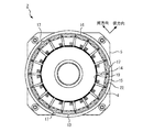
- FIG. 2 is a view of the stator assembly 2 according to the first embodiment as viewed from the axial direction.
- the stator 4 includes a stator core 13, a plurality of windings 14, and a plurality of winding frames 15.
- the stator core 13 is a portion through which the magnetic flux of the rotating magnetic field is passed.
- the stator core 13 is a laminated iron core in which thin plates such as steel plates are laminated in the axial direction.
- Each winding 14 is a portion that generates a magnetic flux of a rotating magnetic field.
- Each winding 14 is connected according to a scheme corresponding to the motor 1 by a connection (not shown).
- Each winding frame 15 corresponds to any winding 14.
- the winding frame 15 is a portion that maintains insulation between the corresponding winding 14 and the stator core 13.
- FIG. 3 is a view of the stator 4 according to the first embodiment as viewed from the axial direction.
- the stator core 13 is an annular part.
- the stator core 13 has a cylindrical outer surface 16.
- the stator core 13 has a plurality of protrusions 17.
- Each protruding portion 17 is a portion that protrudes outward in the radial direction from the cylindrical surface-shaped portion of the outer surface 16.
- the shape of each protrusion 17 is, for example, a rectangular shape.
- the shape of each protrusion 17 may be a rectangular shape curved according to the curvature of the outer surface 16. At this time, the normal of the surface rising in the radial direction from the bottom surface of each protruding portion 17 faces the circumferential direction.
- Each protrusion 17 is formed in such a shape that the product of the total bottom area of each protrusion 17 and the allowable stress of the stator core 13 is larger than the force applied in the circumferential direction by the torque generated by the motor 1. ..
- Each protrusion 17 is provided on the outer surface 16 over all or part of its axial length. The plurality of protrusions 17 are arranged at equal intervals in the circumferential direction.
- the stator core 13 is composed of a plurality of divided bodies 18.
- the stator core 13 is composed of three divided bodies 18.
- the shape of each of the divided bodies 18 is an arc shape.
- the plurality of divided bodies 18 are assembled in an annular shape by, for example, welding, gluing, or caulking.
- each partition 18 contains six magnetic poles 19 as one block.
- one protrusion 17 is provided in each of the three divided bodies 18.
- a plurality of protrusions 17 may be provided in each of the divided bodies 18.
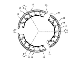
- FIG. 4 is a diagram showing a state before the stator 4 according to the first embodiment is assembled in an annular shape.
- fitting portions 20 are provided at both ends in the circumferential direction.
- the fitting portion 20 is a portion having a concave shape or a convex shape.
- the fitting portion 20 is a portion that is fitted to each other by a concave shape and a convex shape.
- Each of the divided bodies 18 is positioned with each other by the fitting of the fitting portion 20.
- FIG. 5 is a cross-sectional view taken along a plane including the rotation axis of the rotor assembly 3 according to the first embodiment.
- the rotor core 11 is fixed to the shaft body 10 by press fitting.
- Each magnet 12 is inserted into the rotor core 11.
- Each magnet 12 is fixed by, for example, adhesion.
- FIG. 6 is a view of the rotor assembly 3 according to the first embodiment as viewed from the axial direction. In FIG. 6, the rotor assembly 3 seen from the support side bearing 8 side is shown.
- the plurality of magnets 12 are arranged side by side in the circumferential direction. Each magnet 12 is magnetized so that the magnetic poles of adjacent magnets 12 are opposite to each other.
- the support side bearing 8 is press-fitted into the shaft body 10.
- the split body 18 of the stator core 13 is formed.
- FIG. 7 is a diagram showing a steel plate forming the stator core 13 according to the first embodiment.
- the stator core 13 is formed by laminating steel plates punched out by a die or the like.
- the thickness of the steel plate is, for example, about 0.1 mm to 0.5 mm.
- the steel plate is a thin plate made of a material that easily allows magnetic flux to pass through.
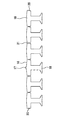
- the steel plate is punched into a shape in which the six magnetic poles 19 of each of the divided bodies 18 are extended in the circumferential direction. At this time, the portions between the adjacent magnetic poles 19 in the steel plate are connected by the thin-walled portion 21 so that the divided body 18 of the stator core 13 can be easily deformed into an arc shape.
- a portion is provided on the outer peripheral portion of the steel plate to form the protruding portion 17 of the stator core 13.
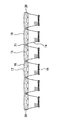
- FIG. 8 is a view of the divided body 18 of the stator core 13 according to the first embodiment as viewed from the inside in the radial direction. In FIG. 8, the split body 18 before being deformed into an arc shape is shown.
- the split body 18 is formed by laminating punched steel plates as shown in FIG. Since the shape of the steel plate is determined by the mold or the like, the stator core 13 does not deteriorate the productivity even if the shape of the cross section of the stator core 13 including the protruding portion 17 perpendicular to the axial direction is complicated. Is easily formed.
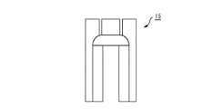
- FIG. 9 is a view of the winding frame 15 according to the first embodiment as viewed from the axial direction of the motor 1.
- the shape of the winding frame 15 is a shape that fits into each magnetic pole 19 of the stator core 13.
- FIG. 10 is a view of the winding frame 15 according to the first embodiment as viewed from the inside of the motor 1 in the radial direction.
- the shape of the winding frame 15 is a shape that covers each magnetic pole 19 of the stator core 13 from the axial direction.
- the winding frame 15 is attached so as to cover the corresponding magnetic pole 19 of the magnetic poles 19 of the divided body 18 of the stator core 13 formed by laminating steel plates.
- FIG. 11 is a view of the split body 18 of the stator core 13 to which the winding frame 15 according to the first embodiment is attached, as viewed from the axial direction of the motor 1.
- the winding frame 15 is attached so as to cover the corresponding magnetic poles 19 from both sides in the axial direction. That is, two winding frames 15 are attached to one magnetic pole 19 from both sides in the axial direction.
- the winding 14 is wound around the winding frame 15 attached to the magnetic pole 19.
- FIG. 12 is a view of the split body 18 of the stator core 13 around which the winding 14 according to the first embodiment is wound, as viewed from the axial direction of the motor 1.
- the winding 14 is wound before the divided body 18 is deformed into an arc shape. Therefore, the winding 14 can be wound more tightly.
- each of the divided bodies 18 of the stator core 13 is deformed into an arc shape.
- FIG. 13 is a view of the divided body 18 of the stator core 13 deformed into an arc shape according to the first embodiment as viewed from the axial direction of the motor 1.
- each winding 14 is connected in a preset order by a connection (not shown).
- the stator assembly 2 is assembled by fixing the stator 4 thus assembled to the housing 5.
- FIG. 14 is a view of the stator assembly 2 before the stator core 13 according to the first embodiment is fixed to the housing 5 as viewed from the axial direction of the motor 1.
- the housing 5 is made of a material having a coefficient of linear expansion larger than that of the stator core 13. Further, the housing 5 is formed of a material having a yield stress lower than that of the stator core 13. The housing 5 is made of a material such as aluminum or an aluminum alloy. The housing 5 has a cylindrical inner surface 22 before the stator 4 is fixed. In this example, the housing 5 does not have irregularities such as grooves on the inner side surface 22 before the stator 4 is fixed.
- the stator core 13 is shrink-fitted and fixed to the housing 5.
- the diameter of the outer surface 16 of the stator core 13 at room temperature is larger than the diameter of the inner surface 22 of the housing 5 at room temperature by the amount of the shrink fitting allowance.
- FIG. 14 shows the stator assembly 2 with the housing 5 heated.
- FIG. 15 is an enlarged view of a main part of the stator assembly 2 according to the first embodiment.
- FIG. 15 shows an enlarged view of the stator assembly 2 in the state shown in FIG.
- the diameter of the inner surface 22 of the housing 5 is larger than the diameter of the outer surface 16 of the stator core 13. Therefore, due to the thermal expansion of the housing 5, when the stator core 13 and the housing 5 are arranged coaxially, a gap is created between the outer surface 16 and the inner surface 22. Further, in the steel plate forming the stator core 13, the height in the radial direction from the outer surface 16 of the protrusion 17 of the stator core 13 is less than half of the dimension obtained by subtracting the shrinkage fitting margin from the thermal expansion amount of the housing 5. It is punched out to be.
- the height of the protruding portion 17 of the stator core 13 when fitted into the housing 5 is equal to or less than the width of the gap between the outer surface 16 and the inner surface 22 caused by the thermal expansion of the housing 5. That is, by thermally expanding the housing 5, the stator core 13 can be fitted into the housing 5 which does not have a groove or the like fitted to the protruding portion 17 on the inner side surface 22. At this time, the protruding portion 17 is arranged so as to face the inner side surface 22 of the housing 5.
- the stator assembly 2 is cooled to room temperature.
- the stator assembly 2 is cooled, for example, by natural cooling.
- the stator assembly 2 may be cooled by forced cooling such as air cooling.
- the stator assembly 2 may be cooled at a cooling rate slower than natural cooling, for example by heating or heat retention.
- the thermally expanded housing 5 contracts, the stator core 13 is shrink-fitted and fixed to the housing 5.
- FIG. 16 is an enlarged view of a main part of the stator assembly 2 according to the first embodiment.
- FIG. 16 shows an enlarged view of the stator assembly 2 after the stator core 13 is fixed to the housing 5.
- the inner surface 22 of the housing 5 comes into contact with the respective protrusions 17 of the stator core 13. As the temperature of the housing 5 further decreases, the diameter of the inner surface 22 of the housing 5 becomes smaller. At this time, the inner side surface 22 of the housing 5 is pressed against the protrusion 17 by contraction. Since the yield stress of the housing 5 is lower than the yield stress of the protrusion 17, the inner surface 22 of the housing 5 is deformed by the protrusion 17. At this time, the inner side surface 22 of the housing 5 is plastically deformed, for example. As the temperature of the housing 5 further decreases, the diameter of the inner surface 22 of the housing 5 becomes smaller.
- the inner side surface 22 of the housing 5 comes into contact with and adheres to the outer surface 16 of the stator core 13.
- the stator core 13 is gripped by the stress of the housing 5 after cooling. In this way, the stator assembly 2 is assembled.
- a rotary electric machine is manufactured by combining the stator assembly 2 and the rotor assembly 3.
- the rotary electric machine is not limited to the permanent magnet type motor.
- the rotary electric machine may be, for example, a motor using an electromagnet for the rotor 9.
- the rotary electric machine may be, for example, a synchronous motor or an induction motor.
- the outer surface 16 of the stator core 13 does not necessarily have to have a cylindrical surface all around in the circumferential direction.
- the stator core 13 may have at least a part of the outer surface 16 having a flat surface on the inner side in the radial direction from the cylindrical surface portion.
- the motor 1 according to the first embodiment includes a stator core 13 and a housing 5.
- the stator core 13 has at least a partially cylindrical outer surface 16.
- the stator core 13 has a plurality of protrusions 17. Each protrusion 17 projects radially outward from the outer surface 16 in the cylindrical portion of the outer surface 16.
- the coefficient of linear expansion of the housing 5 is larger than the coefficient of linear expansion of the stator core 13.
- the housing 5 has a cylindrical inner surface 22. In the housing 5, the inner side surface 22 is in contact with the cylindrical portion of the outer surface 16 of the stator core 13 and the respective protrusions 17 by shrink-fitting and fixing the stator core 13.
- the manufacturing method of the motor 1 according to the first embodiment includes a shrink fitting step.
- the shrink fitting step includes a procedure of fitting the stator core 13 into the housing 5 in an expanded state by heating.
- the shrink fitting step then includes a procedure in which the inner side surface 22 is brought into contact with the cylindrical portion of the outer surface 16 of the stator core 13 and the respective protrusions 17 by contracting the housing 5.
- the motor 1 configured in this way, it is not necessary to insert an insertion member as a separate part between the stator core 13 and the housing 5. Therefore, the man-hours for assembling the motor 1 are less likely to increase. Further, since it is not necessary to provide unevenness such as a groove on the cylindrical inner surface 22 of the housing 5, the housing 5 can be formed by lathe processing or drawing processing. Further, since the inner side surface 22 of the housing 5 has a cylindrical surface shape, a high positioning accuracy requirement is not required. Further, since the stator core 13 is shrink-fitted and fixed, a caulking step or the like is not required after the stator core 13 is fitted into the housing 5. Therefore, the workability of manufacturing the motor 1 is improved.
- stator core 13 is a laminated iron core in which thin plates are laminated in the axial direction.
- the shape of the axial cross section of the stator core 13 can be determined by the die for punching the thin plate. Therefore, even if the shape of the cross section of the stator core 13 including the protrusion 17 is complicated in the axial direction, the stator core 13 can be easily formed without deteriorating the productivity.
- the yield stress of the housing 5 is lower than the yield stress of the stator core 13.
- the inner side surface 22 of the housing 5 is deformed by the respective protrusions 17 due to the shrink fitting fixing. Since the inner side surface 22 of the housing 5 can be plastically deformed, the stator core 13 is firmly and stably held by the housing 5. Since the inner side surface 22 of the housing 5 is plastically deformed by the stator core 13 itself, it is not necessary to separately add a step of plastic working the inner side surface 22 of the housing 5.
- the housing 5 has three or more projecting portions 17 arranged at equal intervals in the circumferential direction as a plurality of projecting portions 17.
- the symmetry in the circumferential direction of the stator 4 is enhanced, so that the radial imbalance of the force related to the stator core 13 is suppressed. Therefore, the positioning accuracy of the central axis of the housing 5 and the stator core 13 is improved.
- the product of the total bottom area of each protrusion 17 and the allowable stress of the stator core 13 is larger than the force applied in the circumferential direction by the torque generated by the rotary electric machine.
- each of the protruding portions 17 a surface whose normal direction faces the circumferential direction is provided.
- each protrusion 17 of the stator core 13 is not limited to a rectangular shape.
- the shape of each protrusion 17 may be, for example, a triangular shape, a trapezoidal shape, a semicircular shape, or the like.
- the shape of each protrusion 17 is such that the circumferential width at the radial tip is narrower than the circumferential width at the radial root.
- the inner side surface 22 is pressed against the protrusion 17 with a higher pressure when the housing 5 contracts. This helps the plastic working of the inner side surface 22 of the housing 5 by each of the protrusions 17.
- Embodiment 2 The differences between the second embodiment and the examples disclosed in the first embodiment will be described in particular detail. As for the features not described in the second embodiment, any of the features disclosed in the first embodiment may be adopted.
- FIG. 17 is an enlarged view of a main part of the stator assembly 2 according to the second embodiment.
- the stator core 13 has a plurality of first recesses 23.
- Each first recess 23 is a portion recessed inward in the radial direction from the outer surface 16.
- the shape of each first recess 23 is, for example, a semicircular shape.
- Each first recess 23 is adjacent to any protrusion 17 in the circumferential direction.
- first recesses 23 are provided on both sides of each protrusion 17 in the circumferential direction.
- Each protrusion 17 has a first protrusion 24 and a second protrusion 25. Each of the first protrusion 24 and the second protrusion 25 projects radially outward from the outer surface 16.
- a second recess 26 is provided between the first protrusion 24 and the second protrusion 25.
- the second recess 26 is a portion that is recessed inward in the radial direction with respect to the tips of the first protrusion 24 and the second protrusion 25.
- the second recess 26 may be inside or outside the outer surface 16 in the radial direction.
- the first recess 23 and the second recess 26 are arranged in the same phase as the magnetic pole 19 of the stator core 13.
- the first protrusion 24 has a first surface 27 on the opposite side of the second recess 26 in the circumferential direction.
- the first surface 27 is, for example, a planar portion whose normal line faces in the circumferential direction.
- the second protrusion 25 has a second surface 28 on the opposite side of the second recess 26 in the circumferential direction.
- the second surface 28 is, for example, a planar portion whose normal line faces in the circumferential direction.
- the normal direction of the second surface 28 is the opposite direction to the normal direction of the first surface 27.
- Each of the first surface 27 and the second surface 28 is a surface facing outward in the circumferential direction in the protrusion 17.
- the normal of the first surface 27 faces in the counterclockwise direction in the circumferential direction.
- the normal of the second surface 28 faces clockwise in the circumferential direction.
- the stator 4 is assembled in the same manner as in the first embodiment, for example. Then, the stator assembly 2 is assembled by shrink-fitting and fixing the assembled stator 4 to the housing 5.
- FIG. 18 is an enlarged view of a main part of the stator assembly 2 according to the second embodiment.
- FIG. 18 shows the stator assembly 2 with the housing 5 heated.
- the height of the steel plate forming the stator core 13 in the radial direction from the outer surface 16 of the first protrusion 24 and the second protrusion 25 is less than half the dimension obtained by subtracting the shrinkage fitting margin from the thermal expansion amount of the housing 5. It is punched out like this. Therefore, the height of the first protrusion 24 and the second protrusion 25 when fitted into the housing 5 is equal to or less than the width of the gap between the outer surface 16 and the inner surface 22 caused by the thermal expansion of the housing 5. That is, by thermally expanding the housing 5, the stator core 13 can be fitted into the housing 5 which does not have a groove or the like fitted to the first protrusion 24 and the second protrusion 25 on the inner side surface 22.
- stator assembly 2 is cooled to room temperature.
- stator core 13 is shrink-fitted and fixed to the housing 5.
- FIG. 19 is an enlarged view of a main part of the stator assembly 2 according to the second embodiment.
- FIG. 19 shows an enlarged view of the stator assembly 2 after the stator core 13 is fixed to the housing 5.
- the inner side surface 22 of the housing 5 comes into contact with the tips of the first protrusion 24 and the second protrusion 25. As the temperature of the housing 5 further decreases, the diameter of the inner surface 22 of the housing 5 becomes smaller. At this time, the inner side surface 22 of the housing 5 is pressed against the first protrusion 24 and the second protrusion 25 by contraction. Since the yield stress of the housing 5 is lower than the yield stress of the stator core 13, the inner side surface 22 of the housing 5 is deformed by the first protrusion 24 and the second protrusion 25. At this time, the first protrusion 24 and the second protrusion 25 are buried in the inner surface 22 of the housing 5.
- the portion of the inner surface 22 of the housing 5 that is deformed by the burial of the first protrusion 24 and the second protrusion 25 is extruded into the first recess 23 or the second recess 26.
- the diameter of the inner surface 22 of the housing 5 becomes smaller.
- the inner surface 22 of the housing 5 comes into contact with the outer surface 16 of the stator core 13.
- the stator core 13 is gripped by the stress of the housing 5 after cooling. In this way, the stator assembly 2 is assembled.
- each of the protruding portions 17 has a first surface 27 and a second surface 28.
- the normal direction of the first surface 27 is a counterclockwise direction in the circumferential direction.
- the normal direction of the second surface 28 is a clockwise direction in the circumferential direction.
- the torque generated in the stator 4 is reliably transmitted by the housing 5 in any rotation direction. Further, even when a gap is formed between the inner side surface 22 of the housing 5 and the outer surface 16 of the stator core 13 due to a temperature change or the like, the contact between the stator core 13 and the housing 5 is ensured.
- the direction of the torque generated in the stator 4 is constant, either the first surface 27 or the second surface 28 is replaced with a surface whose normal direction is inclined with respect to the circumferential direction. May be good.
- stator core 13 has a first recess 23 for each protrusion 17.
- the first recess 23 is a portion of the outer surface 16 that is recessed inward in the radial direction.
- the first recess 23 is adjacent to the protrusion 17 in the circumferential direction.
- the portion of the inner side surface 22 of the housing 5 deformed by shrink fitting fixing can be released to the first recess 23.
- the stator core 13 is more reliably held in the housing 5. Further, the positioning of the stator core 13 with respect to the housing 5 can be effectively performed.
- first recess 23 and the second recess 26 are arranged in the same phase as the magnetic pole 19 of the stator core 13. As a result, the influence of the decrease in the magnetic path cross-sectional area due to the first recess 23 or the second recess 26 is suppressed.
- Embodiment 3 The differences between the third embodiment and the examples disclosed in the first embodiment or the second embodiment will be described in particular detail. As for the features not described in the third embodiment, any of the features disclosed in the first embodiment or the second embodiment may be adopted.
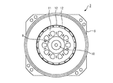
- FIG. 20 is a view of the rotor core 11 according to the third embodiment as viewed from the axial direction.
- each magnet 12 of the rotor 9 is inserted into the hole of the rotor core 11.
- Each magnet 12 constitutes a different magnetic pole in the circumferential direction.
- the 8-pole rotor 9 is configured.
- FIG. 21 is a view of the stator core 13 according to the third embodiment as viewed from the axial direction.
- the stator core 13 is an integral annular portion.
- the stator core 13 is formed by laminating, for example, annularly punched steel plates. At least a part of the outer surface 16 of the stator core 13 is formed in a cylindrical surface shape. The outer surface 16 of the stator core 13 may have a partially flat surface.
- each protrusion 17 is provided on a cylindrical portion of the outer surface 16.
- the stator core 13 includes four protrusions 17. The four protrusions 17 are arranged at equal intervals in the circumferential direction.
- FIG. 22 is a view of the stator assembly 2 according to the third embodiment as viewed from the axial direction.
- Each winding 14 of the stator 4 is wound around the magnetic pole 19 of the stator core 13. Each winding 14 generates a rotating magnetic field by a current flowing under the control of the motor 1.
- the stator core 13 is shrink-fitted and fixed to the housing 5. At this time, the cylindrical portion of the outer surface 16 of the stator core 13 is in contact with the inner surface 22 of the housing 5. On the other hand, a gap may be formed in the flat portion of the outer surface 16 of the stator core 13 and the inner surface 22 of the housing 5.
- FIG. 23 is an enlarged view of a main part of the stator assembly 2 according to the third embodiment.
- the cylindrical portion of the outer surface 16 of the stator core 13 is in contact with the inner surface 22 of the housing 5. Further, the protruding portion 17 of the stator core 13 is embedded in the inner side surface 22 of the housing 5. In this way, the stator core 13 is held by the housing 5.
- the rotary electric machine according to the present disclosure can be applied to a device or the like that uses rotation output from the rotary electric machine.
- the manufacturing method according to the present disclosure can be applied to the rotary electric machine.
Landscapes
- Engineering & Computer Science (AREA)
- Power Engineering (AREA)
- Manufacturing & Machinery (AREA)
- Iron Core Of Rotating Electric Machines (AREA)
Abstract
Sont fournis une machine électrique tournante et un procédé de fabrication d'une machine électrique tournante dont le nombre d'étapes d'assemblage est peu susceptible d'augmenter. Une machine électrique tournante comprend un noyau de stator (13) et un boîtier (5). Le noyau de stator (13) a une surface extérieure (16), dont au moins une partie est une surface cylindrique. Le noyau de stator (13) présente une pluralité de saillies (17). Sur la section de surface cylindrique de la surface extérieure (16), chacune des saillies (17) fait saillie vers l'extérieur depuis la surface extérieure (16), dans la direction radiale. Le coefficient de dilatation linéaire du boîtier (5) est supérieur au coefficient de dilatation linéaire du noyau de stator (13). Le boîtier (5) présente une surface intérieure cylindrique (22). Du fait que le noyau de stator (13) est fixé par ajustage par traction, la surface intérieure cylindrique (22) du boîtier (5) est en contact avec les saillies individuelles (17) et la partie de surface cylindrique de la surface extérieure (16) du noyau de stator (13).
Priority Applications (1)
| Application Number | Priority Date | Filing Date | Title |
|---|---|---|---|
| PCT/JP2020/023612 WO2021255830A1 (fr) | 2020-06-16 | 2020-06-16 | Machine électrique tournante et procédé de fabrication d'une machine électrique tournante |
Applications Claiming Priority (1)
| Application Number | Priority Date | Filing Date | Title |
|---|---|---|---|
| PCT/JP2020/023612 WO2021255830A1 (fr) | 2020-06-16 | 2020-06-16 | Machine électrique tournante et procédé de fabrication d'une machine électrique tournante |
Publications (1)
| Publication Number | Publication Date |
|---|---|
| WO2021255830A1 true WO2021255830A1 (fr) | 2021-12-23 |
Family
ID=79268665
Family Applications (1)
| Application Number | Title | Priority Date | Filing Date |
|---|---|---|---|
| PCT/JP2020/023612 Ceased WO2021255830A1 (fr) | 2020-06-16 | 2020-06-16 | Machine électrique tournante et procédé de fabrication d'une machine électrique tournante |
Country Status (1)
| Country | Link |
|---|---|
| WO (1) | WO2021255830A1 (fr) |
Citations (4)
| Publication number | Priority date | Publication date | Assignee | Title |
|---|---|---|---|---|
| JPS6291538U (fr) * | 1985-11-27 | 1987-06-11 | ||
| JP2004180449A (ja) * | 2002-11-28 | 2004-06-24 | Asmo Co Ltd | パワーステアリング装置用ブラシレスモータ |
| WO2015186455A1 (fr) * | 2014-06-06 | 2015-12-10 | 三菱電機株式会社 | Moteur à aimants permanents, et moteur à aimants permanents à entraînement intégré |
| WO2017134740A1 (fr) * | 2016-02-02 | 2017-08-10 | 三菱電機株式会社 | Stator et compresseur |
-
2020
- 2020-06-16 WO PCT/JP2020/023612 patent/WO2021255830A1/fr not_active Ceased
Patent Citations (4)
| Publication number | Priority date | Publication date | Assignee | Title |
|---|---|---|---|---|
| JPS6291538U (fr) * | 1985-11-27 | 1987-06-11 | ||
| JP2004180449A (ja) * | 2002-11-28 | 2004-06-24 | Asmo Co Ltd | パワーステアリング装置用ブラシレスモータ |
| WO2015186455A1 (fr) * | 2014-06-06 | 2015-12-10 | 三菱電機株式会社 | Moteur à aimants permanents, et moteur à aimants permanents à entraînement intégré |
| WO2017134740A1 (fr) * | 2016-02-02 | 2017-08-10 | 三菱電機株式会社 | Stator et compresseur |
Similar Documents
| Publication | Publication Date | Title |
|---|---|---|
| JP7344807B2 (ja) | コイルボビン、分布巻ラジアルギャップ型回転電機の固定子コア及び分布巻ラジアルギャップ型回転電機 | |
| JP5879121B2 (ja) | アキシャルギャップ回転電機 | |
| EP1087498B1 (fr) | Moteur-générateur avec noyaux séparés | |
| US9735636B2 (en) | Rotor and dynamo-electric machine having the same | |
| US8368270B2 (en) | Stator of electric rotating machine | |
| KR20030044747A (ko) | 전동기 | |
| US20180041080A1 (en) | Rotor, rotary electric machine, and method for manufacturing rotor | |
| JP2003088013A (ja) | 回転電機 | |
| JP2010239691A (ja) | 回転電機の固定子及び回転電機 | |
| CN108370178A (zh) | 轴向间隙型旋转电机及其制造方法 | |
| JP2022082518A (ja) | 2分節擬似ハルバッハモータの回転子及びその製造方法 | |
| JP2014033549A (ja) | ロータ、回転電機及びロータの製造方法 | |
| JP4940469B2 (ja) | 発電機 | |
| JP2004112856A (ja) | 回転電機の冷却構造及びその製造方法 | |
| JP2000278903A (ja) | 電動機及びその製造方法 | |
| JP2007089295A (ja) | 回転電機およびレゾルバ | |
| WO2018066109A1 (fr) | Machine dynamo-électrique de type à rotor extérieur | |
| JP2009060754A (ja) | ステータ用コア、ステータ、その組立方法およびモータ | |
| US20060066166A1 (en) | Rotor body for the rotor of an electric machine and a method for the manufacture of a rotor body | |
| WO2021131298A1 (fr) | Machine électrique rotative | |
| JP2011166984A (ja) | モータ | |
| JP3657155B2 (ja) | 2軸同期型電動機 | |
| JP5068102B2 (ja) | 永久磁石式回転電機及びその回転子 | |
| JP2007166754A (ja) | 分割コアを備えた回転電機およびその製造方法 | |
| JP2005094927A (ja) | 回転電機および回転電機に用いられる電機子用駆動コイル |
Legal Events
| Date | Code | Title | Description |
|---|---|---|---|
| 121 | Ep: the epo has been informed by wipo that ep was designated in this application |
Ref document number: 20941166 Country of ref document: EP Kind code of ref document: A1 |
|
| NENP | Non-entry into the national phase |
Ref country code: DE |
|
| 122 | Ep: pct application non-entry in european phase |
Ref document number: 20941166 Country of ref document: EP Kind code of ref document: A1 |
|
| NENP | Non-entry into the national phase |
Ref country code: JP |