WO2017134746A1 - Procédé d'envoi de liquide, et système de détection et dispositif de détection utilisant ledit procédé - Google Patents
Procédé d'envoi de liquide, et système de détection et dispositif de détection utilisant ledit procédé Download PDFInfo
- Publication number
- WO2017134746A1 WO2017134746A1 PCT/JP2016/053077 JP2016053077W WO2017134746A1 WO 2017134746 A1 WO2017134746 A1 WO 2017134746A1 JP 2016053077 W JP2016053077 W JP 2016053077W WO 2017134746 A1 WO2017134746 A1 WO 2017134746A1
- Authority
- WO
- WIPO (PCT)
- Prior art keywords
- liquid
- liquid injection
- pipette tip
- injection part
- detection
- Prior art date
- Legal status (The legal status is an assumption and is not a legal conclusion. Google has not performed a legal analysis and makes no representation as to the accuracy of the status listed.)
- Ceased
Links
Images



Classifications
-
- B—PERFORMING OPERATIONS; TRANSPORTING
- B01—PHYSICAL OR CHEMICAL PROCESSES OR APPARATUS IN GENERAL
- B01L—CHEMICAL OR PHYSICAL LABORATORY APPARATUS FOR GENERAL USE
- B01L3/00—Containers or dishes for laboratory use, e.g. laboratory glassware; Droppers
- B01L3/50—Containers for the purpose of retaining a material to be analysed, e.g. test tubes
- B01L3/502—Containers for the purpose of retaining a material to be analysed, e.g. test tubes with fluid transport, e.g. in multi-compartment structures
- B01L3/5027—Containers for the purpose of retaining a material to be analysed, e.g. test tubes with fluid transport, e.g. in multi-compartment structures by integrated microfluidic structures, i.e. dimensions of channels and chambers are such that surface tension forces are important, e.g. lab-on-a-chip
- B01L3/502715—Containers for the purpose of retaining a material to be analysed, e.g. test tubes with fluid transport, e.g. in multi-compartment structures by integrated microfluidic structures, i.e. dimensions of channels and chambers are such that surface tension forces are important, e.g. lab-on-a-chip characterised by interfacing components, e.g. fluidic, electrical, optical or mechanical interfaces
-
- B—PERFORMING OPERATIONS; TRANSPORTING
- B01—PHYSICAL OR CHEMICAL PROCESSES OR APPARATUS IN GENERAL
- B01L—CHEMICAL OR PHYSICAL LABORATORY APPARATUS FOR GENERAL USE
- B01L3/00—Containers or dishes for laboratory use, e.g. laboratory glassware; Droppers
- B01L3/02—Burettes; Pipettes
- B01L3/021—Pipettes, i.e. with only one conduit for withdrawing and redistributing liquids
- B01L3/0217—Pipettes, i.e. with only one conduit for withdrawing and redistributing liquids of the plunger pump type
-
- B—PERFORMING OPERATIONS; TRANSPORTING
- B01—PHYSICAL OR CHEMICAL PROCESSES OR APPARATUS IN GENERAL
- B01L—CHEMICAL OR PHYSICAL LABORATORY APPARATUS FOR GENERAL USE
- B01L3/00—Containers or dishes for laboratory use, e.g. laboratory glassware; Droppers
- B01L3/50—Containers for the purpose of retaining a material to be analysed, e.g. test tubes
- B01L3/502—Containers for the purpose of retaining a material to be analysed, e.g. test tubes with fluid transport, e.g. in multi-compartment structures
- B01L3/5027—Containers for the purpose of retaining a material to be analysed, e.g. test tubes with fluid transport, e.g. in multi-compartment structures by integrated microfluidic structures, i.e. dimensions of channels and chambers are such that surface tension forces are important, e.g. lab-on-a-chip
- B01L3/50273—Containers for the purpose of retaining a material to be analysed, e.g. test tubes with fluid transport, e.g. in multi-compartment structures by integrated microfluidic structures, i.e. dimensions of channels and chambers are such that surface tension forces are important, e.g. lab-on-a-chip characterised by the means or forces applied to move the fluids
-
- G—PHYSICS
- G01—MEASURING; TESTING
- G01N—INVESTIGATING OR ANALYSING MATERIALS BY DETERMINING THEIR CHEMICAL OR PHYSICAL PROPERTIES
- G01N1/00—Sampling; Preparing specimens for investigation
-
- G—PHYSICS
- G01—MEASURING; TESTING
- G01N—INVESTIGATING OR ANALYSING MATERIALS BY DETERMINING THEIR CHEMICAL OR PHYSICAL PROPERTIES
- G01N1/00—Sampling; Preparing specimens for investigation
- G01N1/02—Devices for withdrawing samples
- G01N1/10—Devices for withdrawing samples in the liquid or fluent state
- G01N1/14—Suction devices, e.g. pumps; Ejector devices
-
- G—PHYSICS
- G01—MEASURING; TESTING
- G01N—INVESTIGATING OR ANALYSING MATERIALS BY DETERMINING THEIR CHEMICAL OR PHYSICAL PROPERTIES
- G01N21/00—Investigating or analysing materials by the use of optical means, i.e. using sub-millimetre waves, infrared, visible or ultraviolet light
- G01N21/01—Arrangements or apparatus for facilitating the optical investigation
- G01N21/11—Filling or emptying of cuvettes
-
- G—PHYSICS
- G01—MEASURING; TESTING
- G01N—INVESTIGATING OR ANALYSING MATERIALS BY DETERMINING THEIR CHEMICAL OR PHYSICAL PROPERTIES
- G01N21/00—Investigating or analysing materials by the use of optical means, i.e. using sub-millimetre waves, infrared, visible or ultraviolet light
- G01N21/62—Systems in which the material investigated is excited whereby it emits light or causes a change in wavelength of the incident light
- G01N21/63—Systems in which the material investigated is excited whereby it emits light or causes a change in wavelength of the incident light optically excited
- G01N21/64—Fluorescence; Phosphorescence
- G01N21/645—Specially adapted constructive features of fluorimeters
- G01N21/648—Specially adapted constructive features of fluorimeters using evanescent coupling or surface plasmon coupling for the excitation of fluorescence
-
- G—PHYSICS
- G01—MEASURING; TESTING
- G01N—INVESTIGATING OR ANALYSING MATERIALS BY DETERMINING THEIR CHEMICAL OR PHYSICAL PROPERTIES
- G01N35/00—Automatic analysis not limited to methods or materials provided for in any single one of groups G01N1/00 - G01N33/00; Handling materials therefor
- G01N35/10—Devices for transferring samples or any liquids to, in, or from, the analysis apparatus, e.g. suction devices, injection devices
-
- B—PERFORMING OPERATIONS; TRANSPORTING
- B01—PHYSICAL OR CHEMICAL PROCESSES OR APPARATUS IN GENERAL
- B01L—CHEMICAL OR PHYSICAL LABORATORY APPARATUS FOR GENERAL USE
- B01L2200/00—Solutions for specific problems relating to chemical or physical laboratory apparatus
- B01L2200/02—Adapting objects or devices to another
- B01L2200/026—Fluid interfacing between devices or objects, e.g. connectors, inlet details
-
- B—PERFORMING OPERATIONS; TRANSPORTING
- B01—PHYSICAL OR CHEMICAL PROCESSES OR APPARATUS IN GENERAL
- B01L—CHEMICAL OR PHYSICAL LABORATORY APPARATUS FOR GENERAL USE
- B01L2200/00—Solutions for specific problems relating to chemical or physical laboratory apparatus
- B01L2200/02—Adapting objects or devices to another
- B01L2200/026—Fluid interfacing between devices or objects, e.g. connectors, inlet details
- B01L2200/027—Fluid interfacing between devices or objects, e.g. connectors, inlet details for microfluidic devices
-
- B—PERFORMING OPERATIONS; TRANSPORTING
- B01—PHYSICAL OR CHEMICAL PROCESSES OR APPARATUS IN GENERAL
- B01L—CHEMICAL OR PHYSICAL LABORATORY APPARATUS FOR GENERAL USE
- B01L2200/00—Solutions for specific problems relating to chemical or physical laboratory apparatus
- B01L2200/06—Fluid handling related problems
- B01L2200/0684—Venting, avoiding backpressure, avoid gas bubbles
-
- B—PERFORMING OPERATIONS; TRANSPORTING
- B01—PHYSICAL OR CHEMICAL PROCESSES OR APPARATUS IN GENERAL
- B01L—CHEMICAL OR PHYSICAL LABORATORY APPARATUS FOR GENERAL USE
- B01L2300/00—Additional constructional details
- B01L2300/04—Closures and closing means
- B01L2300/041—Connecting closures to device or container
- B01L2300/044—Connecting closures to device or container pierceable, e.g. films, membranes
-
- B—PERFORMING OPERATIONS; TRANSPORTING
- B01—PHYSICAL OR CHEMICAL PROCESSES OR APPARATUS IN GENERAL
- B01L—CHEMICAL OR PHYSICAL LABORATORY APPARATUS FOR GENERAL USE
- B01L2300/00—Additional constructional details
- B01L2300/08—Geometry, shape and general structure
- B01L2300/0809—Geometry, shape and general structure rectangular shaped
-
- B—PERFORMING OPERATIONS; TRANSPORTING
- B01—PHYSICAL OR CHEMICAL PROCESSES OR APPARATUS IN GENERAL
- B01L—CHEMICAL OR PHYSICAL LABORATORY APPARATUS FOR GENERAL USE
- B01L2400/00—Moving or stopping fluids
- B01L2400/04—Moving fluids with specific forces or mechanical means
- B01L2400/0475—Moving fluids with specific forces or mechanical means specific mechanical means and fluid pressure
- B01L2400/0487—Moving fluids with specific forces or mechanical means specific mechanical means and fluid pressure fluid pressure, pneumatics
-
- B—PERFORMING OPERATIONS; TRANSPORTING
- B01—PHYSICAL OR CHEMICAL PROCESSES OR APPARATUS IN GENERAL
- B01L—CHEMICAL OR PHYSICAL LABORATORY APPARATUS FOR GENERAL USE
- B01L2400/00—Moving or stopping fluids
- B01L2400/06—Valves, specific forms thereof
- B01L2400/0694—Valves, specific forms thereof vents used to stop and induce flow, backpressure valves
-
- B—PERFORMING OPERATIONS; TRANSPORTING
- B01—PHYSICAL OR CHEMICAL PROCESSES OR APPARATUS IN GENERAL
- B01L—CHEMICAL OR PHYSICAL LABORATORY APPARATUS FOR GENERAL USE
- B01L3/00—Containers or dishes for laboratory use, e.g. laboratory glassware; Droppers
- B01L3/02—Burettes; Pipettes
- B01L3/0275—Interchangeable or disposable dispensing tips
-
- G—PHYSICS
- G01—MEASURING; TESTING
- G01N—INVESTIGATING OR ANALYSING MATERIALS BY DETERMINING THEIR CHEMICAL OR PHYSICAL PROPERTIES
- G01N21/00—Investigating or analysing materials by the use of optical means, i.e. using sub-millimetre waves, infrared, visible or ultraviolet light
- G01N21/01—Arrangements or apparatus for facilitating the optical investigation
- G01N21/03—Cuvette constructions
- G01N2021/0346—Capillary cells; Microcells
-
- G—PHYSICS
- G01—MEASURING; TESTING
- G01N—INVESTIGATING OR ANALYSING MATERIALS BY DETERMINING THEIR CHEMICAL OR PHYSICAL PROPERTIES
- G01N21/00—Investigating or analysing materials by the use of optical means, i.e. using sub-millimetre waves, infrared, visible or ultraviolet light
- G01N21/62—Systems in which the material investigated is excited whereby it emits light or causes a change in wavelength of the incident light
- G01N21/63—Systems in which the material investigated is excited whereby it emits light or causes a change in wavelength of the incident light optically excited
- G01N21/64—Fluorescence; Phosphorescence
- G01N21/645—Specially adapted constructive features of fluorimeters
- G01N2021/6482—Sample cells, cuvettes
Definitions
- the present invention relates to a liquid feeding method for supplying a liquid to a fine channel, and a detection system and a detection apparatus for performing the method.
- Biochemical reactions such as antigen-antibody reactions are used in biochemical tests.
- a fluorescence immunoassay hereinafter also referred to as “FIA”
- a labeling substance containing a fluorescent substance is reacted with a substance to be detected (antigen).
- a substance to be detected antigen
- the target substance labeled with the labeling substance is irradiated with excitation light, and the fluorescence emitted from the fluorescent substance is detected.
- the amount of the substance to be detected is specified from the detected fluorescence intensity or the like.
- SPFS surface plasmon excitation enhanced fluorescence spectrometry
- a first capturing body for example, a primary antibody
- a reaction field for capturing the substance to be detected.
- the reaction field is formed in a fine channel.
- a to-be-detected substance is combined with a 1st capture body by sending the solution containing a to-be-detected substance to the said flow path (reaction field).
- a second capture body for example, a secondary antibody
- labeled with a fluorescent substance is sent to the flow path to further bind the second antibody to the substance to be detected that is bound to the primary antibody. . That is, the substance to be detected is indirectly labeled with a fluorescent substance.
- the fluorescent material When the metal film is irradiated with excitation light in this state, the fluorescent material is excited by localized field light enhanced by surface plasmon resonance (hereinafter also referred to as “SPR”), and emits fluorescence.
- SPR surface plasmon resonance
- the substance to be detected can be detected by detecting the fluorescence emitted by the fluorescent substance.
- the chance of contact between the substance to be detected and the first capturing body can be increased by reciprocating the sample in the flow path.
- a sufficient amount of a substance to be detected can be bound to one capturing body.
- the cleaning agent for cleaning the flow path and the second capturing body are similarly sent back and forth.
- the bubbles 510 cover the first capturing body 502.
- the detected substance 501 cannot bind to the first capturing body 502. If such a bubble 510 exists, it is impossible to sufficiently clean the fine channel 41 and to combine the second capturing body.
- Patent Document 1 proposes to adjust the timing of liquid injection and suction when various liquids such as a specimen, a washing liquid, and a second antibody are sent back and forth through a fine channel.
- various liquids 500 are supplied into the microchannel 41 by injecting various liquids 500 into the liquid injection part 3101 using the pipette tip 134. Further, as shown in FIG. 9B, the liquid 500 in the liquid injection part 3101 is sucked by the pipette tip 134 so that the liquid 500 flows in the fine channel 41 in the direction opposite to that at the time of liquid injection. . Then, by repeating the injection and suction of the liquid 500, the liquid 500 is reciprocated into the fine channel 41. However, as shown in FIG.
- FIG. 9C is a partially enlarged view of a region indicated by a broken line in FIG. 9B.
- FIG. 9C shows that after the liquid 500 is supplied, the liquid level 500A is unlikely to become horizontal in the liquid injection part 3101. Therefore, a gap is likely to be formed between the liquid level 10A and the tip of the pipette tip 134.
- the liquid 500 is sucked in this state, air is also sucked together with the liquid 500. That is, even if the timing of liquid injection and suction is adjusted as in Patent Document 1, it is difficult to sufficiently prevent air from entering the fine flow path of the detection chip.
- the liquid injection portion of the detection chip In the embodiment in which the pipette tip is inserted into the liquid injection portion of the detection chip, the liquid is injected and sucked, and the liquid is reciprocated into the fine channel, the liquid injection portion is negatively charged after the liquid injection. It has been found that by generating the pressure, the liquid level of the liquid in the liquid injection part rises, and it becomes difficult to suck air when sucking the liquid.
- a liquid feeding method is connected to a fine channel, a liquid injection unit for injecting a liquid, connected to one end of the fine channel, and connected to the other end of the fine channel.
- a pipette tip is inserted into the liquid injection portion of the detection chip having a storage portion for temporarily storing the liquid so that the liquid injection portion is in a hermetically sealed state. Is fed and sucked, and a liquid is fed back and forth in the fine channel.
- the pipette tip is inserted into the liquid injection part until the tip of the pipette tip is below the liquid level;
- a process of sucking or injecting liquid into the liquid injection part by the pipette tip and sucking the liquid in the liquid injection part is performed in this order.
- the detection system is connected to a micro flow channel, a liquid injection unit for injecting liquid connected to one end of the micro flow channel, and the other end of the micro flow channel.
- a detection chip having a storage part for temporarily storing liquid, a pipette chip for injecting liquid into the liquid injection part, and sucking liquid from the liquid injection part, and liquid by the pipette chip
- a liquid feed pump drive mechanism for controlling the injection and suction of the liquid, and the pipette tip is hermetically sealed in the liquid injection portion, and the tip of the pipette tip is injected into the liquid injection portion
- the liquid feed pump drive mechanism is inserted below the liquid level of the liquid to be injected, and after the liquid is injected from the pipette tip into the liquid injection part, While maintaining the state, the pipette tip is raised in the axial direction to increase the height of the liquid level in the liquid injection section, and the pipette tip sucks the liquid from the liquid injection section, or
- the detection device is connected to a fine channel, a liquid injection unit for injecting a liquid connected to one end of the fine channel, and the other end of the fine channel.
- the pipette tip is inserted so that the tip of the pipette tip is below the liquid level of the liquid to be injected into the liquid injection portion.
- the liquid level of the liquid in the liquid injection part is increased by raising the pipette tip in the axial direction while maintaining the sealed state in the liquid injection part. Then, the liquid is sucked from the liquid injection part by the pipette tip, or the liquid is injected into the liquid injection part by the pipette tip and the liquid in the liquid injection part is sucked.
- liquid feeding method and the detection device of the present invention it is possible to reciprocate liquid into the fine channel without allowing air to enter the fine channel.
- FIG. 1 is a schematic diagram showing a configuration of a detection device (SPFS device) according to an embodiment of the present invention.
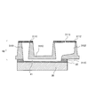
- FIG. 2 is a partially enlarged view showing a part of the detection chip of the detection apparatus according to the embodiment of the present invention.
- 3A and 3B are schematic views showing a liquid feeding method according to an embodiment of the present invention.
- FIG. 4 is a flowchart of a liquid feeding method according to an embodiment of the present invention, and is a flowchart illustrating an example of an operation procedure of the detection apparatus.
- FIG. 5A is a graph showing the relationship between the passage of time (horizontal axis) and the pressure in the liquid injection part (vertical axis) when the liquid feeding method of one embodiment of the present invention is performed, and FIG.
- FIG. 5A is an enlarged view of a region within a dotted line frame of 5A, and is a graph showing the relationship between the amount of movement of the pipette tip in the axial direction and the pressure in the liquid injection part in the step of raising the liquid level of the liquid.
- FIG. 6 is a flowchart of a detection method according to an embodiment of the present invention, and is a flowchart illustrating an example of an operation procedure of the detection apparatus.
- FIG. 7 is a perspective view of a metal film including a diffraction grating.
- FIG. 8 is a schematic diagram for explaining a conventional liquid feeding method.
- FIG. 9 is a schematic diagram for explaining a conventional liquid feeding method.
- a detection chip used for SPFS and an SPFS device will be described as representative examples of the detection chip, but the detection chip and detection device of the present invention are not limited to these.
- FIG. 1 is a schematic diagram showing a configuration of an SPFS apparatus 100 (detection system) used in an embodiment of the present invention.
- the SPFS device 100 includes an excitation light irradiation unit 110, a fluorescence detection unit 120, a liquid feeding unit 130, a transport unit 140, and a control unit 150.
- the detection chip 10 is mounted on the chip holder 142 of the transport unit 140, and the excitation light ⁇ is irradiated so that surface plasmon resonance is generated on the metal film 30 of the detection chip 10, and based on the surface plasmon resonance. Generates localized field light.
- the presence or amount of the to-be-detected substance in a specimen is measured by exciting the fluorescent substance which exists on the metal film 30 with the said local field light, and detecting fluorescence (beta) which a fluorescent substance emits.
- the detection chip 10 is attached to the chip holder of the detection device, and the detection chip 10 is formed so as to be removable from the detection device.
- the detection chip, the detection system, and the detection apparatus used in the present embodiment will be described first, and then, a method for supplying various liquids to the detection chip and a detection method for a substance to be detected using the detection apparatus will be described. .
- the detection chip 10 of this embodiment includes a prism 20 having an incident surface 21, a film formation surface 22, and an emission surface 23, and a metal film 30 formed on the film formation surface 22 of the prism 20. And a flow path cover 40 disposed on the film forming surface 22 of the prism 20 or the metal film 30.
- FIG. 2 shows a longitudinal sectional view of the detection chip 10 at an angle different from that of FIG. As shown in FIG. 2, the channel lid 40 has a recess on the surface facing the metal film 30.
- a space surrounded by the metal film 30 and the channel lid 40 includes a fine channel 41 for reciprocating the liquid 500 (for example, a specimen), a liquid injection unit 3101 for injecting the liquid 500, and It becomes the storage part 3102 for storing the liquid 500 temporarily.
- the liquid 500 for example, a specimen
- a liquid injection unit 3101 for injecting the liquid 500
- the channel lid 40 of the present embodiment has recesses corresponding to the liquid injection part 3101, the fine channel 41, and the storage part 3102, and is open to the upper part of the liquid injection part 3101 and the upper part of the storage part 3102.
- the frame 3110 is formed of a material that is transparent to light (for example, fluorescence ⁇ and plasmon scattered light ⁇ ).
- a part thereof may be formed of a material that is opaque to light.
- the material transparent to light include a resin.
- the flow path lid 40 is bonded to the metal film 30 via an adhesive layer 3115 such as a double-sided tape or an adhesive.
- the flow path lid 40 is formed by laser welding, ultrasonic welding, clamping member. It may be joined to the metal film 30 or the prism 20 of the detection chip 10 by pressure bonding or the like.
- the liquid injection part covering sheet 3111 can insert the pipette tip 134.
- the liquid injection part covering sheet 3111 is in close contact with the outer periphery of the pipette tip 134, and the liquid injection part 3101 is sealed.
- “the liquid injection part 3101 is in a sealed state” means a state where the liquid injection part 3101 and the outside are not in direct communication.
- the liquid injection part covering sheet 3111 can be, for example, a sheet composed of two layers (not shown) of an elastic sheet and an adhesive sheet. Further, the liquid injection portion covering sheet 3111 may have a fine through hole for inserting the pipette tip 134. In this embodiment, the liquid injection part covering sheet 3111 is provided with an initial hole having an outer diameter of 1.2 mm.
- the elastic sheet may be, for example, a polyurethane sheet having a tensile elastic constant of 0.05 to 2 GPa, a tensile breaking elongation of 200 to 2000%, and a tear strength of 80 to 3000 mN, but when the pipette tip 134 is inserted, the pipette tip 134 is inserted.
- the polyurethane sheet is not limited as long as it can be in close contact with the outer periphery.
- Examples of elastic sheets other than polyurethane sheets include low density polyethylene (LDPE), linear low density polyethylene (LLDPE), medium density polyethylene (MDPE), nylon, unstretched polypropylene (CPP), ethylene-vinyl alcohol copolymer Examples include a sheet made of coalescence (EVOH), silicone, polyvinyl alcohol (PVA), polyvinyl chloride (PVC), and the like.
- the thickness of the elastic sheet is not particularly limited, but can be about 100 ⁇ m, for example.
- the pressure-sensitive adhesive sheet is not particularly limited as long as it is made of a material capable of sticking an elastic sheet to the frame 3110.
- the reservoir covering sheet 3112 is a vent hole for adjusting the pressure in the space (the space consisting of the liquid injection portion 3101, the fine channel 41, and the reservoir 3102) formed by the metal film 30 and the channel lid 40. Any sheet having 3113 may be used.
- the material of the storage part covering sheet 3112 is not particularly limited, and can be made of the same material as the liquid injection part covering sheet 3111 described above.
- the first capturing body is fixed to the metal film 30 in the fine channel 41.
- the first capturing body is a substance having a recognition site for specifically binding to the substance to be detected in the specimen.
- the substance to be detected selectively binds to the first capturing body. That is, the substance to be detected is arranged in the fine channel 41. This makes it possible to detect the substance to be detected as will be described later.
- the type of the first capturing body fixed on the metal film 30 is not particularly limited as long as it has a recognition site for specifically binding to the substance to be detected.
- the width and height of the fine channel 41 are not particularly limited, and are appropriately selected according to the application of the detection chip 10 and the like.
- a pipette tip 134 is inserted into the liquid injection part 3101 formed by the metal film 30 and the flow path lid 40 as shown in FIG. Then, the liquid 500 is reciprocated into the microchannel 41 by injecting the liquid 500 into the liquid injection unit 3101 with the pipette tip 134 or sucking the liquid 500 in the liquid injection unit 3101 with the pipette tip 134. Deliver liquid.
- the volume and shape of the liquid injection part 3101 are appropriately selected according to the shape of the pipette tip 134. However, in the present embodiment, as will be described later, when the liquid 500 is reciprocated, the pipette tip 134 is raised in the axial direction to generate a negative pressure in the liquid injection unit 3101.
- the inner diameter of the liquid injection part 3101 is preferably in an appropriate range with respect to the outer diameter of the pipette tip 134.
- the inner diameter of the liquid injection part 3101 is 10 mm or less, and the outer diameter of the pipette tip 134 is 1 mm or more and less than 10 mm.
- the inner diameter of the liquid injection part 3101 means the maximum value of the inner diameter of the liquid injection part 3101, and the cross section of the liquid injection part 3101 does not have to be circular.
- the outer diameter of the pipette tip 134 refers to the maximum value of the outer diameter of the pipette tip 134, and the cross-section of the pipette tip 134 may not be circular.
- the liquid 500 flows into the reservoir 3102 formed by the metal film 30 and the flow path lid 40 when the liquid 500 is reciprocated to the fine flow path 41 as shown in FIG.
- the liquid 500 that has flowed into the storage unit 3102 is stirred in the storage unit 3102.
- the concentration of the active component (for example, the substance to be detected or the cleaning component) of the liquid (sample or cleaning liquid) 500 passing through the microchannel 41 becomes uniform, and the microchannel Various reactions are likely to occur in 41, and the cleaning effect is increased.
- the volume and shape of the storage unit 3102 are not particularly limited as long as the liquid 500 can be sufficiently stored when the liquid 500 is reciprocated.
- the prism 20 included in the detection chip 10 is made of a dielectric that is transparent to the excitation light ⁇ , and has an incident surface 21, a film formation surface 22, and an output surface 23 as shown in FIG.
- the incident surface 21 is a surface for causing the excitation light ⁇ from the excitation light irradiation unit 110 to enter the prism 20.
- the metal film 30 is disposed on the film formation surface 22, and the excitation light ⁇ incident on the inside of the prism 20 is reflected on the back surface of the metal film 30, more specifically, between the prism 20 and the metal film 30. Reflected at the interface (deposition surface 22).
- the emission surface 23 is a surface for emitting the reflected light reflected by the film formation surface 22 to the outside of the prism 20.
- the shape of the prism 20 is not particularly limited.
- the shape of the prism 20 is a column having a trapezoidal bottom surface.
- the surface corresponding to one base of the trapezoid is the film formation surface 22, the surface corresponding to one leg is the incident surface 21, and the surface corresponding to the other leg is the emission surface 23.
- the trapezoid serving as the bottom surface is preferably an isosceles trapezoid. Thereby, the entrance surface 21 and the exit surface 23 are symmetric, and the S wave component of the excitation light ⁇ is less likely to stay in the prism 20.
- the incident surface 21 is formed so that the excitation light ⁇ does not return to the excitation light irradiation unit 110.
- the light source of the excitation light ⁇ is a laser diode (hereinafter also referred to as “LD”)
- LD laser diode
- the angle of the incident surface 21 is set so that the excitation light ⁇ does not enter the incident surface 21 perpendicularly in a scanning range centered on an ideal resonance angle or enhancement angle.
- the “resonance angle” means an incident angle when the amount of reflected light emitted from the emission surface 23 is minimized when the incident angle of the excitation light ⁇ with respect to the metal film 30 is scanned.
- the “enhancement angle” refers to scattered light having the same wavelength as the excitation light ⁇ emitted above the detection chip 10 when the incident angle of the excitation light ⁇ with respect to the metal film 30 is scanned (hereinafter referred to as “plasmon scattered light”). It means the incident angle when the amount of ⁇ is maximized.
- the angle between the incident surface 21 and the film formation surface 22 and the angle between the film formation surface 22 and the output surface 23 are both about 80 °.
- the resonance angle (and the enhancement angle near the pole) is generally determined by the design of the detection chip 10.
- the design factors are the refractive index of the prism 20, the refractive index of the metal film 30, the film thickness of the metal film 30, the extinction coefficient of the metal film 30, the wavelength of the excitation light ⁇ , and the like.
- the resonance angle and the enhancement angle are shifted by the detection target substance captured on the metal film 30 via the first capturing body, but the amount is less than several degrees.
- the prism 20 has a considerable amount of birefringence.
- Examples of the material of the prism 20 include resin and glass.
- the material of the prism 20 is preferably a resin having a refractive index of 1.4 to 1.6 and a small birefringence.
- the metal film 30 is disposed on the film formation surface 22 of the prism 20.
- an interaction occurs between the photon of the excitation light ⁇ incident on the film formation surface 22 under total reflection conditions and the free electrons in the metal film 30, and a localized field is formed on the surface of the metal film 30.
- Light generally referred to as “evanescent light” or “near-field light” is generated.
- the material of the metal film 30 is not particularly limited as long as it is a metal that can cause surface plasmon resonance.
- Examples of the material of the metal film 30 include gold, silver, copper, aluminum, and alloys thereof.
- the method for forming the metal film 30 is not particularly limited. Examples of the method for forming the metal film 30 include sputtering, vapor deposition, and plating.
- the thickness of the metal film 30 is not particularly limited, but is preferably in the range of 30 to 70 nm.
- the detection chip 10 is normally replaced for each measurement.
- the detection chip 10 is preferably a structure having a length of several millimeters to several centimeters for each piece, but is a smaller structure or a larger structure not included in the category of “chip”. Also good.
- the SPFS apparatus 100 includes the excitation light irradiation unit 110, the fluorescence detection unit 120, the liquid feeding unit 130, the transport unit 140, and the control unit 150.
- the excitation light irradiation unit 110 irradiates the detection chip 10 held by the chip holder 142 with excitation light ⁇ .
- the excitation light irradiation unit 110 emits only the P wave with respect to the metal film 30 toward the incident surface 21 so that the incident angle with respect to the metal film 30 is an angle that causes SPR.
- the “excitation light” is light that directly or indirectly excites the fluorescent material.
- the excitation light ⁇ is light that generates localized field light on the surface of the metal film 30 that excites the fluorescent material when the metal film 30 is irradiated through the prism 20 at an angle at which SPR occurs.
- the excitation light irradiation unit 110 includes a light source unit 111, an angle adjustment mechanism 112, and a light source control unit 113.
- the light source unit 111 emits the collimated excitation light ⁇ having a constant wavelength and light amount so that the shape of the irradiation spot on the back surface of the metal film 30 is substantially circular.
- the light source unit 111 includes, for example, a light source of excitation light ⁇ , a beam shaping optical system, an APC mechanism, and a temperature adjustment mechanism (all not shown).
- the type of the light source is not particularly limited, and one example is a laser diode (LD).
- Other examples of light sources include light emitting diodes, mercury lamps, and other laser light sources.
- the light emitted from the light source is not a beam, the light emitted from the light source is converted into a beam by a lens, a mirror, a slit, or the like.
- the light emitted from the light source is not monochromatic light, the light emitted from the light source is converted into monochromatic light by a diffraction grating or the like.
- the light emitted from the light source is not linearly polarized light, the light emitted from the light source is converted into linearly polarized light by a polarizer or the like.
- the beam shaping optical system includes, for example, a collimator, a band pass filter, a linear polarization filter, a half-wave plate, a slit, and a zoom means.
- the beam shaping optical system may include all of these or a part thereof.
- the collimator collimates the excitation light ⁇ emitted from the light source.
- the band-pass filter turns the excitation light ⁇ emitted from the light source into narrowband light having only the center wavelength. This is because the excitation light ⁇ from the light source has a slight wavelength distribution width.
- the linear polarization filter turns the excitation light ⁇ emitted from the light source into completely linearly polarized light.
- the half-wave plate adjusts the polarization direction of the excitation light ⁇ so that the P-wave component is incident on the metal film 30.
- the slit and zoom means adjust the beam diameter, contour shape, and the like of the excitation light ⁇ so that the shape of the irradiation spot on the back surface of the metal film 30 is a circle having a predetermined size.
- the APC mechanism controls the light source so that the output of the light source is constant. More specifically, the APC mechanism detects the amount of light branched from the excitation light ⁇ with a photodiode (not shown) or the like. The APC mechanism controls the input energy by a regression circuit, thereby controlling the output of the light source to be constant.
- the temperature adjustment mechanism is, for example, a heater or a Peltier element.
- the wavelength and energy of the light emitted from the light source may vary depending on the temperature. For this reason, the wavelength and energy of the light emitted from the light source are controlled to be constant by keeping the temperature of the light source constant by the temperature adjusting mechanism.
- the angle adjustment mechanism 112 adjusts the incident angle of the excitation light ⁇ with respect to the metal film 30 (the interface (deposition surface 22) between the prism 20 and the metal film 30).
- the angle adjusting mechanism 112 relatively irradiates the optical axis of the excitation light ⁇ and the chip holder 142 in order to irradiate the excitation light ⁇ at a predetermined incident angle toward a predetermined position of the metal film 30 via the prism 20. Rotate.
- the angle adjustment mechanism 112 rotates the light source unit 111 around an axis (axis perpendicular to the paper surface of FIG. 1) orthogonal to the optical axis of the excitation light ⁇ .
- the position of the rotation axis is set so that the position of the irradiation spot on the metal film 30 hardly changes even when the incident angle is scanned.
- the angle at which the amount of plasmon scattered light ⁇ is maximum is the enhancement angle.
- the basic incident condition of the excitation light ⁇ is determined by the material and shape of the prism 20 of the detection chip 10, the film thickness of the metal film 30, the refractive index of the liquid 500 in the microchannel 41, etc.
- the optimum incident condition varies slightly. For this reason, it is preferable to obtain an optimal enhancement angle for each measurement.
- the light source control unit 113 controls various devices included in the light source unit 111 to control the emission of the excitation light ⁇ from the light source unit 111.
- the light source control unit 113 includes, for example, a known computer or microcomputer including an arithmetic device, a control device, a storage device, an input device, and an output device.
- the fluorescence detection unit 120 detects the fluorescence ⁇ generated by irradiating the metal film 30 with the excitation light ⁇ . Further, as necessary, the fluorescence detection unit 120 also detects plasmon scattered light ⁇ generated by irradiation of the excitation light ⁇ to the metal film 30.
- the fluorescence detection unit 120 includes a light receiving unit 121, a position switching mechanism 122, and a sensor control unit 123.
- the light receiving unit 121 is arranged in the normal direction of the metal film 30 of the detection chip 10.
- the light receiving unit 121 includes a first lens 124, an optical filter 125, a second lens 126, and a light receiving sensor 127.
- the first lens 124 is, for example, a condensing lens, and condenses light emitted from the metal film 30.
- the second lens 126 is an imaging lens, for example, and forms an image of the light collected by the first lens 124 on the light receiving surface of the light receiving sensor 127.
- the optical path between both lenses is a substantially parallel optical path.
- the optical filter 125 is disposed between both lenses.
- the optical filter 125 guides only the fluorescence component to the light receiving sensor 127 and removes the excitation light component (plasmon scattered light ⁇ ) in order to detect the fluorescence ⁇ with a high S (signal) / N (noise) ratio.
- the optical filter 125 include an excitation light reflection filter, a short wavelength cut filter, and a band pass filter.
- the optical filter 125 is, for example, a filter including a multilayer film that reflects a predetermined light component, or a color glass filter that absorbs a predetermined light component.
- the light receiving sensor 127 detects fluorescence ⁇ and plasmon scattered light ⁇ .
- the light receiving sensor 127 has a high sensitivity capable of detecting weak fluorescence ⁇ from a minute amount of a substance to be detected.
- the light receiving sensor 127 is, for example, a photomultiplier tube (PMT) or an avalanche photodiode (APD).
- the position switching mechanism 122 switches the position of the optical filter 125 on or off the optical path in the light receiving unit 121. Specifically, when the light receiving sensor 127 detects the fluorescence ⁇ , the optical filter 125 is disposed on the optical path of the light receiving unit 121, and when the light receiving sensor 127 detects the plasmon scattered light ⁇ , the optical filter 125 is connected to the light receiving unit 121. Placed outside the optical path.
- the sensor control unit 123 controls detection of an output value of the light receiving sensor 127, management of sensitivity of the light receiving sensor 127 based on the detected output value, change of sensitivity of the light receiving sensor 127 for obtaining an appropriate output value, and the like.
- the sensor control unit 123 includes, for example, a known computer or microcomputer including an arithmetic device, a control device, a storage device, an input device, and an output device.
- the liquid supply unit 130 supplies various liquids 500 into the liquid injection part 3101 of the detection chip 10 held by the chip holder 142 and reciprocates the liquid.
- a specimen, a cleaning liquid, a labeling liquid containing a second capturing body labeled with a fluorescent substance (hereinafter also referred to as “labeling liquid”), and the like are supplied into the liquid injection unit 3101.
- the liquid feeding unit 130 includes a liquid chip 131, a syringe pump 132, and a liquid feeding pump driving mechanism 133.
- the liquid chip 131 is a container for storing a liquid such as a specimen, a cleaning liquid, or a labeling liquid.
- a liquid chip 131 a plurality of containers are usually arranged according to the type of liquid, or a chip in which a plurality of containers are integrated is arranged.
- the syringe pump 132 in the liquid feeding unit 130 includes a pipette tip 134 and a plunger 135 that can reciprocate inside the syringe pump 132. By the reciprocating motion of the plunger 135, the liquid is sucked and discharged from the pipette tip 134 quantitatively. If the pipette tip 134 is replaceable, the pipette tip 134 need not be cleaned. For this reason, it is preferable from the viewpoint of preventing contamination of impurities. When the pipette tip 134 is not configured to be replaceable, it is possible to use the pipette tip 134 without replacement by further adding a configuration for cleaning the inside of the pipette tip 134.
- the area of the lid 40 of the detection chip 10 that contacts the liquid injection portion covering sheet 3111 preferably has a constant outer diameter, and preferably has a cylindrical shape.
- an outer diameter does not need to be constant but can be made into arbitrary shapes.
- the liquid feed pump drive mechanism 133 includes a drive device for the plunger 135 and a moving device for the syringe pump 132.
- the drive device of the plunger 135 is a device for reciprocating the plunger 135 and includes, for example, a stepping motor.
- a drive device including a stepping motor is preferable from the viewpoint of managing the amount of liquid remaining in the detection chip 10 because it can manage the amount and speed of the syringe pump 132.
- the moving device of the syringe pump 132 moves the syringe pump 132 freely in two directions, for example, an axial direction (for example, a vertical direction) of the pipette tip 134 and a direction (for example, a horizontal direction) crossing the axial direction.
- the moving device of the syringe pump 132 is configured by, for example, a robot arm, a two-axis stage, or a turntable that can move up and down.
- the liquid feed pump drive mechanism 133 drives the syringe pump 132 and the plunger 135 in the syringe pump 132 to suck various liquids 500 from the liquid chip 131. Then, the syringe pump 132 is moved to insert the pipette tip 134 into the liquid injection part 3101 of the detection chip 10 and inject various liquids 500. At this time, as shown in FIG. 3A, after supplying the liquid 500 to the liquid injection unit 3101, the syringe pump 132 (pipette) is used so that the tip of the pipette tip 134 is lower than the liquid level of the liquid 500 in the liquid injection unit 3101. The position of the tip 134) in the axial direction is controlled.
- the liquid feed pump drive mechanism 133 moves the pipette tip 134 to the upper side in the axial direction, as shown in FIG. 3B, and generates a negative pressure in the liquid injection part.
- the plunger 135 is moved to suck the liquid 500 or inject and suck the liquid 500.
- the liquid 500 is reciprocated into the fine channel 41.
- the reciprocating liquid feeding the inside of the fine channel 41 is washed, the first capturing body and the substance to be detected are reacted in the fine channel 41, or the second substance labeled with the substance to be detected and the fluorescent substance is used. It reacts with the capturing body.
- the transport unit 140 transports the detection chip 10 to the measurement position or the liquid feeding position and fixes it.
- the “measurement position” is a position where the excitation light irradiation unit 110 irradiates the detection chip 10 with the excitation light ⁇ , and the fluorescence detection unit 120 detects the fluorescence ⁇ or the plasmon scattered light ⁇ generated accordingly.
- the “liquid feeding position” means that the liquid feeding unit 130 supplies liquid into the liquid injection part 3101 of the detection chip 10 or sucks the liquid in the flow channel 41 of the detection chip 10 from the liquid injection part 3101 ( This is the position to be removed.
- the transport unit 140 includes a transport stage 141 and a chip holder 142.
- the chip holder 142 is fixed to the transfer stage 141, and holds the detection chip 10 in a detachable manner.
- the shape of the chip holder 142 is a shape that can hold the detection chip 10 and does not disturb the optical paths of the excitation light ⁇ , the fluorescence ⁇ , and the plasmon scattered light ⁇ .
- the chip holder 142 is provided with an opening through which excitation light ⁇ , fluorescence ⁇ , and plasmon scattered light ⁇ pass.
- the transfer stage 141 moves the chip holder 142 in one direction and in the opposite direction.
- the transport stage 141 also has a shape that does not interfere with the optical paths of the excitation light ⁇ , fluorescence ⁇ , and plasmon scattered light ⁇ .
- the transport stage 141 is driven by, for example, a stepping motor.
- the control unit 150 controls the angle adjustment mechanism 112, the light source control unit 113, the position switching mechanism 122, the sensor control unit 123, the liquid feed pump drive mechanism 133, and the transport stage 141.
- the control unit 150 includes, for example, a known computer or microcomputer including an arithmetic device, a control device, a storage device, an input device, and an output device.
- FIG. 4 is a flowchart illustrating an example of an operation procedure of the SPFS apparatus 100 when performing the detection method of the present embodiment.
- FIG. 5A shows the relationship between the passage of time (horizontal axis) when the liquid feeding method of the present embodiment is performed and the pressure (vertical axis) in the liquid injection unit 3101. The value on the vertical axis in FIG. 5A is a differential pressure when the pressure in the liquid injection part 3101 at the time of inserting the pipette tip is used as a reference (0 kPa).
- the liquid feed pump drive mechanism 133 of the SPFS device 100 drives the syringe pump 132 and the plunger 135 in the syringe pump 132 to suck various liquids 500 from the liquid chip 131.
- the pipette tip 134 is inserted into the liquid injection part 3101 of the detection tip 10 (step S110).
- the insertion position of the pipette tip 134 is controlled so that the tip of the pipette tip 134 is lower than the liquid level of the liquid 500 injected into the liquid injection part 3101 after the liquid 500 is supplied.
- the pressure in the liquid injection part 3101 hardly changes because the reservoir covering sheet 3112 has the vent holes 3113.
- the liquid feed pump drive mechanism 133 drives the plunger 135 to supply a desired amount of the liquid 500 from the pipette tip 134 into the liquid injection part 3101 (step S120).
- the liquid feed pump drive mechanism 133 drives the plunger 135 to supply a desired amount of the liquid 500 from the pipette tip 134 into the liquid injection part 3101 (step S120).
- pressure is applied in the liquid supply unit 3101, and the liquid 500 flows from the liquid supply unit 3101 into the microchannel 41. At this time, all or a part of the liquid 500 may be discharged.
- the liquid feed pump drive mechanism 133 controls the position of the syringe pump 132 in the axial direction, and moves the pipette tip 134 upward in the axial direction while maintaining the sealed state in the liquid injection portion.
- produces in the liquid injection
- the distance from the tip of the pipette tip 134 to the liquid level (the height represented by h2 in FIG. 3B) is the distance from the tip of the pipette tip 134 to the liquid level before negative pressure is generated.
- FIG. 5B shows the relationship between the amount of movement of the pipette tip 134 in the axial direction and the pressure change in the liquid injection part 3101 in the step of raising the liquid level of the liquid 500 (step S130).
- 5B is an enlarged view of the area within the dotted line frame in FIG. 5A, and the value on the vertical axis in FIG. 5B is a value when the pressure in the liquid injection part 3101 when the pipette tip 134 is inserted is set as a reference (0 kPa). Differential pressure. As shown in FIG.
- the pipette tip 134 is moved 1000 ⁇ m or less upward in the axial direction. From the viewpoint of sufficiently generating a negative pressure, it is more preferable that the moving distance of the pipette tip 134 upward in the axial direction is 100 to 500 ⁇ m.
- the amount of pressure reduction inside the liquid injection portion caused by the movement of the pipette tip 134 is preferably 1.0 kPa or less from the viewpoint of raising the liquid level appropriately.
- the liquid feed pump drive mechanism 133 drives the plunger 135 to suck the liquid 500 in the liquid injection unit 3101 with the pipette tip 134 or inject and suck the liquid 500 with the pipette tip 134 (step S140).
- the liquid 500 is sucked, all of the liquid in the liquid injecting unit 3101 may be sucked or only a part may be sucked.
- the liquid 500 remains in the pipette tip 134. Therefore, in this step, the liquid 500 remaining in the pipette tip 134 may be discharged.
- step S140 the discharge and suction of the liquid (step S140) are repeated as many times as necessary, and the liquid 500 is reciprocated into the fine channel 41.
- the substance to be detected is bound to the first capturing body, the fine flow path is washed, or the second capturing body is further bound to the substance to be detected bound to the first capturing body.
- the liquid is agitated in the pipette tip 134 or in the storage unit 3101, and the concentration of the liquid provided in the microchannel 41 is made uniform, or the reaction ( For example, an antigen-antibody reaction) can be promoted.
- the liquid feed pump drive mechanism 133 drives the plunger 135 to suck the liquid in the liquid injection part 3101, the fine channel 41, and the storage part 3102. Thereafter, the pipette tip 134 is moved from the liquid injection unit 3101 to discharge the liquid 500 to the liquid tip 131 or the like.
- FIG. 6 is a flowchart illustrating an example of an operation procedure of the SPFS apparatus 100 when performing the detection method of the present embodiment.
- step S10 preparation for detection is performed (step S10). Specifically, the above-described detection chip 10 is installed in the chip holder 142 of the SPSF device 100. Further, when a moisturizing agent is present in the flow channel 41 of the detection chip 10, the inside of the flow channel 41 is washed to remove the moisturizing agent.
- the incident angle of the excitation light ⁇ with respect to the metal film 30 (deposition surface 22) of the detection chip 10 is set to an enhancement angle (step S20).
- the control unit 150 controls the transfer stage 141 to move the detection chip 10 from the installation position to the detection position.
- the control unit 150 controls the light source control unit 113 and the angle adjustment unit 112 to irradiate the excitation light ⁇ from the light source unit 111 to a predetermined position of the metal film 30 (deposition surface 22).
- the incident angle of the excitation light ⁇ with respect to 30 (deposition surface 22) is scanned.
- the control unit 150 controls the position switching mechanism 122 to move the optical filter 125 out of the optical path of the light receiving unit 121.
- control unit 150 controls the sensor control unit 123 so that the light receiving sensor 127 detects the plasmon scattered light ⁇ .
- the control unit 150 obtains data including the relationship between the incident angle of the excitation light ⁇ and the intensity of the plasmon scattered light ⁇ .
- the control unit 150 analyzes the data and determines an incident angle (enhancement angle) that maximizes the intensity of the plasmon scattered light ⁇ .
- the control unit 150 controls the angle adjustment unit 112 to set the incident angle of the excitation light ⁇ with respect to the metal film 30 (deposition surface 22) as an enhancement angle.
- the enhancement angle is determined by the material and shape of the prism 20, the thickness of the metal film 30, the refractive index of the liquid in the flow channel 41, and the like. It varies slightly due to various factors such as shape error. For this reason, it is preferable to determine the enhancement angle each time detection is performed.
- the enhancement angle is determined on the order of about 0.1 °.
- the specimen is provided to the fine channel 41 of the detection chip 10 by the above-described liquid feeding method, and the target substance contained in the specimen is contained in the first capturing body fixed on the metal film 30 in the detection chip 10. Are specifically bound (primary reaction (step S30)).
- the buffer solution or the like is provided in the fine channel 41 by the above-described liquid feeding method, and the inside of the fine channel 41 is washed to remove the free substance to be detected.
- the types of the specimen and the substance to be detected provided to the fine channel 41 in the present embodiment are not particularly limited.
- the specimen include body fluids such as blood, serum, plasma, urine, nasal fluid, saliva, semen, and diluted solutions thereof.
- substances to be detected contained in these specimens include nucleic acids (such as DNA and RNA), proteins (such as polypeptides and oligopeptides), amino acids, carbohydrates, lipids, and modified molecules thereof.
- the optical blank value is measured (Step S40). Specifically, the control unit 150 controls the transfer stage 141 to move the detection chip 10 from the installation position to the detection position. Thereafter, the control unit 150 controls the light source control unit 113 to emit the excitation light ⁇ from the light source unit 111 at an enhancement angle toward the metal film 30 (deposition surface 22). At the same time, the control unit 150 controls the sensor control unit 123 to detect the amount of light by the light receiving sensor 127, and records this as a blank value.
- the second capturing body labeled with the fluorescent material is bound to the substance to be detected bound to the first capturing body on the metal film 30 (secondary reaction (step S50)).
- the control unit 150 controls the transport stage 141 to move the detection chip 10 from the detection position to the liquid feeding position. Thereafter, the control unit 150 controls the liquid feeding pump drive mechanism 133 to provide the labeling liquid including the second capturing body into the fine channel 41 by the above-described liquid feeding method.
- the second capturing body is a substance that specifically binds to a portion of the detected substance that is different from the portion to which the first capturing body specifically binds.
- a fluorescent substance is bound to the second capturing body.
- the second capturing body specifically binds to the target substance bound to the first capturing body, and the target substance is indirectly a fluorescent substance. Be labeled.
- a buffer solution or the like is provided in the fine channel 41 by the above-described liquid feeding method, the inside of the fine channel 41 is washed, and a free second capturing body. And so on.
- the second capturing body only needs to be a substance that specifically binds to a site different from the site where the first capturing body specifically binds to the target substance, and is specific to the target substance. It may be a biomolecule or a fragment thereof.
- the second capturing body may be composed of one molecule or a complex in which two or more molecules are complexed.
- the excitation light ⁇ is increased through the prism 20 at an enhancement angle.
- the metal film 30 (deposition surface 22) is irradiated.
- the fluorescence value from the fluorescent substance which labels a to-be-detected substance is measured (measurement process (process S60)).
- the control unit 150 controls the transfer stage 141 to move the detection chip 10 from the liquid feeding position to the detection position.
- the control unit 150 controls the light source control unit 113 to emit the excitation light ⁇ from the light source unit 111 toward the metal film 30 (film formation surface 22).
- the control unit 150 controls the sensor control unit 123 to detect the amount of light having the same wavelength as the fluorescence ⁇ by the light receiving sensor 127.
- the fluorescence value mainly includes a fluorescence component (signal value) derived from a fluorescent substance that labels the substance to be detected, and an optical blank value. Therefore, the control unit 150 can calculate a signal value correlated with the amount of the substance to be detected by subtracting the optical blank value obtained in step S40 from the fluorescence value obtained in step S60. Then, it is converted into the amount and concentration of the substance to be detected by a calibration curve prepared in advance.
- the mode in which the negative pressure is generated by moving the pipette tip 134 in the axial direction upward in the step of generating the negative pressure in the liquid injection unit 3101 has been described.
- the negative pressure can also be generated in the liquid injection part 3101 by other methods such as deforming the liquid injection part covering sheet 3111 of the road lid 40.
- FIG. 7 is a perspective view of the metal film 30a including the diffraction grating.
- a detection chip having a metal film 30a including a diffraction grating may be used.
- photons and surface plasmons can be combined to emit plasmon scattered light ⁇ from the metal film 30a.
- the light irradiation unit 110 is disposed on the metal film 30a side of the detection chip, and irradiates the excitation light ⁇ toward the diffraction grating in the fluorescence ⁇ detection step and the plasmon scattered light ⁇ detection step.
- the detection method and the detection device using the SPFS device have been described.
- the detection method and the detection device are not limited to these.
- the detection method of the substance to be detected can be applied to the ELISA method, the RIfS method, the SPR method, the QCM, and the like.
- various liquids can be reciprocated without causing air to enter the fine flow path. Therefore, it is very useful as a detection device for detecting various substances to be detected and a method for feeding a sample or the like to the detection device.
Landscapes
- Chemical & Material Sciences (AREA)
- Health & Medical Sciences (AREA)
- General Health & Medical Sciences (AREA)
- Analytical Chemistry (AREA)
- Life Sciences & Earth Sciences (AREA)
- Immunology (AREA)
- Biochemistry (AREA)
- General Physics & Mathematics (AREA)
- Physics & Mathematics (AREA)
- Pathology (AREA)
- Chemical Kinetics & Catalysis (AREA)
- Clinical Laboratory Science (AREA)
- Hematology (AREA)
- Dispersion Chemistry (AREA)
- Nuclear Medicine, Radiotherapy & Molecular Imaging (AREA)
- Hydrology & Water Resources (AREA)
- Investigating, Analyzing Materials By Fluorescence Or Luminescence (AREA)
- Automatic Analysis And Handling Materials Therefor (AREA)
- Optical Measuring Cells (AREA)
Abstract
Priority Applications (4)
| Application Number | Priority Date | Filing Date | Title |
|---|---|---|---|
| EP16889236.2A EP3413056B1 (fr) | 2016-02-02 | 2016-02-02 | Procédé d'envoi de liquide, et système de détection utilisant ledit procédé |
| PCT/JP2016/053077 WO2017134746A1 (fr) | 2016-02-02 | 2016-02-02 | Procédé d'envoi de liquide, et système de détection et dispositif de détection utilisant ledit procédé |
| JP2017565001A JP6690655B2 (ja) | 2016-02-02 | 2016-02-02 | 送液方法、ならびにこれを行う検出システムおよび検出装置 |
| US16/074,022 US11045803B2 (en) | 2016-02-02 | 2016-02-02 | Liquid delivery method, and detection system and detection apparatus for implementation of this method |
Applications Claiming Priority (1)
| Application Number | Priority Date | Filing Date | Title |
|---|---|---|---|
| PCT/JP2016/053077 WO2017134746A1 (fr) | 2016-02-02 | 2016-02-02 | Procédé d'envoi de liquide, et système de détection et dispositif de détection utilisant ledit procédé |
Publications (1)
| Publication Number | Publication Date |
|---|---|
| WO2017134746A1 true WO2017134746A1 (fr) | 2017-08-10 |
Family
ID=59499530
Family Applications (1)
| Application Number | Title | Priority Date | Filing Date |
|---|---|---|---|
| PCT/JP2016/053077 Ceased WO2017134746A1 (fr) | 2016-02-02 | 2016-02-02 | Procédé d'envoi de liquide, et système de détection et dispositif de détection utilisant ledit procédé |
Country Status (4)
| Country | Link |
|---|---|
| US (1) | US11045803B2 (fr) |
| EP (1) | EP3413056B1 (fr) |
| JP (1) | JP6690655B2 (fr) |
| WO (1) | WO2017134746A1 (fr) |
Cited By (2)
| Publication number | Priority date | Publication date | Assignee | Title |
|---|---|---|---|---|
| JP2020146666A (ja) * | 2019-03-15 | 2020-09-17 | コニカミノルタ株式会社 | 送液ノズル、反応方法及び反応装置 |
| WO2021245989A1 (fr) * | 2020-06-01 | 2021-12-09 | 株式会社日立ハイテク | Analyseur automatique |
Families Citing this family (2)
| Publication number | Priority date | Publication date | Assignee | Title |
|---|---|---|---|---|
| WO2019015947A1 (fr) * | 2017-07-19 | 2019-01-24 | Fundació Institut De Ciències Fotòniques | Dispositif de détection microfluidique portatif |
| GB201902810D0 (en) * | 2019-03-01 | 2019-04-17 | Vidya Holdings Ltd | Disposition of reagents in assay device |
Citations (5)
| Publication number | Priority date | Publication date | Assignee | Title |
|---|---|---|---|---|
| WO1997044671A1 (fr) * | 1996-05-20 | 1997-11-27 | Precision System Science Co., Ltd. | Procede et appareil pour commander des particules magnetiques a l'aide d'une machine de pipettage |
| WO2011027851A1 (fr) * | 2009-09-07 | 2011-03-10 | コニカミノルタホールディングス株式会社 | Système d'alimentation en liquide pour micropuce, dispositif de détection d'échantillons et procédé d'alimentation en liquide pour système d'alimentation en liquide d'une micropuce |
| JP2012159358A (ja) * | 2011-01-31 | 2012-08-23 | Konica Minolta Holdings Inc | 検査システム、及びこの検査システムに用いられる送液装置 |
| WO2012172992A1 (fr) * | 2011-06-14 | 2012-12-20 | コニカミノルタホールディングス株式会社 | Puce de capteur utilisée dans un dispositif de détection d'échantillon et dispositif de détection d'échantillon utilisant la puce de capteur |
| WO2015064441A1 (fr) * | 2013-10-31 | 2015-05-07 | コニカミノルタ株式会社 | Méthode de détection d'antigènes mettant en oeuvre une méthode de dosage sandwich |
Family Cites Families (8)
| Publication number | Priority date | Publication date | Assignee | Title |
|---|---|---|---|---|
| DE10052819B4 (de) * | 2000-10-24 | 2004-02-19 | Fraunhofer-Gesellschaft zur Förderung der angewandten Forschung e.V. | Pipettensystem und Pipettenarray sowie Verfahren zum Befüllen eines Pipettensystems |
| JP4148778B2 (ja) * | 2001-03-09 | 2008-09-10 | バイオミクロ システムズ インコーポレイティッド | アレイとのミクロ流体的インターフェース機器 |
| US20030157503A1 (en) * | 2003-04-04 | 2003-08-21 | Mcgarry Mark W | Compositions and methods for performing biological reactions |
| JP2013185967A (ja) * | 2012-03-08 | 2013-09-19 | Konica Minolta Inc | 生化学検査装置 |
| JP6098807B2 (ja) * | 2012-04-20 | 2017-03-22 | Tdk株式会社 | 塗布ヘッド及び液滴塗布装置 |
| US9075042B2 (en) * | 2012-05-15 | 2015-07-07 | Wellstat Diagnostics, Llc | Diagnostic systems and cartridges |
| JP5980030B2 (ja) * | 2012-07-23 | 2016-08-31 | 株式会社日立ハイテクノロジーズ | 生化学処理装置 |
| US9365408B2 (en) * | 2012-11-16 | 2016-06-14 | Zhejiang Jm Industry Co., Ltd. | Auto refill perfume atomizer |
-
2016
- 2016-02-02 US US16/074,022 patent/US11045803B2/en active Active
- 2016-02-02 EP EP16889236.2A patent/EP3413056B1/fr active Active
- 2016-02-02 WO PCT/JP2016/053077 patent/WO2017134746A1/fr not_active Ceased
- 2016-02-02 JP JP2017565001A patent/JP6690655B2/ja active Active
Patent Citations (5)
| Publication number | Priority date | Publication date | Assignee | Title |
|---|---|---|---|---|
| WO1997044671A1 (fr) * | 1996-05-20 | 1997-11-27 | Precision System Science Co., Ltd. | Procede et appareil pour commander des particules magnetiques a l'aide d'une machine de pipettage |
| WO2011027851A1 (fr) * | 2009-09-07 | 2011-03-10 | コニカミノルタホールディングス株式会社 | Système d'alimentation en liquide pour micropuce, dispositif de détection d'échantillons et procédé d'alimentation en liquide pour système d'alimentation en liquide d'une micropuce |
| JP2012159358A (ja) * | 2011-01-31 | 2012-08-23 | Konica Minolta Holdings Inc | 検査システム、及びこの検査システムに用いられる送液装置 |
| WO2012172992A1 (fr) * | 2011-06-14 | 2012-12-20 | コニカミノルタホールディングス株式会社 | Puce de capteur utilisée dans un dispositif de détection d'échantillon et dispositif de détection d'échantillon utilisant la puce de capteur |
| WO2015064441A1 (fr) * | 2013-10-31 | 2015-05-07 | コニカミノルタ株式会社 | Méthode de détection d'antigènes mettant en oeuvre une méthode de dosage sandwich |
Cited By (5)
| Publication number | Priority date | Publication date | Assignee | Title |
|---|---|---|---|---|
| JP2020146666A (ja) * | 2019-03-15 | 2020-09-17 | コニカミノルタ株式会社 | 送液ノズル、反応方法及び反応装置 |
| JP7111037B2 (ja) | 2019-03-15 | 2022-08-02 | コニカミノルタ株式会社 | 反応装置及び反応方法 |
| WO2021245989A1 (fr) * | 2020-06-01 | 2021-12-09 | 株式会社日立ハイテク | Analyseur automatique |
| JPWO2021245989A1 (fr) * | 2020-06-01 | 2021-12-09 | ||
| JP7305891B2 (ja) | 2020-06-01 | 2023-07-10 | 株式会社日立ハイテク | 自動分析装置 |
Also Published As
| Publication number | Publication date |
|---|---|
| US11045803B2 (en) | 2021-06-29 |
| EP3413056A4 (fr) | 2018-12-12 |
| US20190039067A1 (en) | 2019-02-07 |
| EP3413056B1 (fr) | 2019-12-18 |
| EP3413056A1 (fr) | 2018-12-12 |
| JP6690655B2 (ja) | 2020-04-28 |
| JPWO2017134746A1 (ja) | 2018-11-29 |
Similar Documents
| Publication | Publication Date | Title |
|---|---|---|
| JP6337905B2 (ja) | 表面プラズモン共鳴蛍光分析方法および表面プラズモン共鳴蛍光分析装置 | |
| JP6424890B2 (ja) | 表面プラズモン増強蛍光測定方法、表面プラズモン増強蛍光測定装置および分析チップ | |
| JP6399089B2 (ja) | 表面プラズモン共鳴蛍光分析方法、表面プラズモン共鳴蛍光分析装置および位置合わせ方法 | |
| JP6638721B2 (ja) | 検出方法および反応装置 | |
| JP6801656B2 (ja) | 検出装置および検出方法 | |
| WO2017082069A1 (fr) | Procédé de réaction | |
| JP6747455B2 (ja) | 検出方法、検出システム、および検出装置 | |
| JP6690655B2 (ja) | 送液方法、ならびにこれを行う検出システムおよび検出装置 | |
| JPWO2017082089A1 (ja) | 表面プラズモン共鳴蛍光分析方法および表面プラズモン共鳴蛍光分析装置 | |
| JPWO2016132945A1 (ja) | 反応方法および反応装置 | |
| JPWO2016208421A1 (ja) | 測定方法、並びにこれに用いる測定チップ、及び測定用キット | |
| JP6922907B2 (ja) | 反応方法、ならびにこれを行う反応システムおよび反応装置 | |
| JP6642592B2 (ja) | 送液方法、ならびにこれを行う検出システムおよび検出装置 | |
| JPWO2017057136A1 (ja) | 表面プラズモン励起増強蛍光分光測定方法、および測定用キット | |
| JPWO2017086128A1 (ja) | 検出方法、検出装置および検査用キット | |
| JPWO2018179950A1 (ja) | 検体検出システム用センサーチップ |
Legal Events
| Date | Code | Title | Description |
|---|---|---|---|
| 121 | Ep: the epo has been informed by wipo that ep was designated in this application |
Ref document number: 16889236 Country of ref document: EP Kind code of ref document: A1 |
|
| ENP | Entry into the national phase |
Ref document number: 2017565001 Country of ref document: JP Kind code of ref document: A |
|
| NENP | Non-entry into the national phase |
Ref country code: DE |
|
| WWE | Wipo information: entry into national phase |
Ref document number: 2016889236 Country of ref document: EP |
|
| ENP | Entry into the national phase |
Ref document number: 2016889236 Country of ref document: EP Effective date: 20180903 |