WO2017134891A1 - Dispositif de distribution de fluide et dispositif de retraitement d'endoscope - Google Patents
Dispositif de distribution de fluide et dispositif de retraitement d'endoscope Download PDFInfo
- Publication number
- WO2017134891A1 WO2017134891A1 PCT/JP2016/083426 JP2016083426W WO2017134891A1 WO 2017134891 A1 WO2017134891 A1 WO 2017134891A1 JP 2016083426 W JP2016083426 W JP 2016083426W WO 2017134891 A1 WO2017134891 A1 WO 2017134891A1
- Authority
- WO
- WIPO (PCT)
- Prior art keywords
- flow path
- fluid
- container
- unit
- resistance
- Prior art date
- Legal status (The legal status is an assumption and is not a legal conclusion. Google has not performed a legal analysis and makes no representation as to the accuracy of the status listed.)
- Ceased
Links
Images


Classifications
-
- A—HUMAN NECESSITIES
- A61—MEDICAL OR VETERINARY SCIENCE; HYGIENE
- A61B—DIAGNOSIS; SURGERY; IDENTIFICATION
- A61B1/00—Instruments for performing medical examinations of the interior of cavities or tubes of the body by visual or photographical inspection, e.g. endoscopes; Illuminating arrangements therefor
- A61B1/12—Instruments for performing medical examinations of the interior of cavities or tubes of the body by visual or photographical inspection, e.g. endoscopes; Illuminating arrangements therefor with cooling or rinsing arrangements
- A61B1/121—Instruments for performing medical examinations of the interior of cavities or tubes of the body by visual or photographical inspection, e.g. endoscopes; Illuminating arrangements therefor with cooling or rinsing arrangements provided with means for cleaning post-use
- A61B1/123—Instruments for performing medical examinations of the interior of cavities or tubes of the body by visual or photographical inspection, e.g. endoscopes; Illuminating arrangements therefor with cooling or rinsing arrangements provided with means for cleaning post-use using washing machines
-
- A—HUMAN NECESSITIES
- A61—MEDICAL OR VETERINARY SCIENCE; HYGIENE
- A61B—DIAGNOSIS; SURGERY; IDENTIFICATION
- A61B1/00—Instruments for performing medical examinations of the interior of cavities or tubes of the body by visual or photographical inspection, e.g. endoscopes; Illuminating arrangements therefor
- A61B1/12—Instruments for performing medical examinations of the interior of cavities or tubes of the body by visual or photographical inspection, e.g. endoscopes; Illuminating arrangements therefor with cooling or rinsing arrangements
- A61B1/121—Instruments for performing medical examinations of the interior of cavities or tubes of the body by visual or photographical inspection, e.g. endoscopes; Illuminating arrangements therefor with cooling or rinsing arrangements provided with means for cleaning post-use
- A61B1/125—Instruments for performing medical examinations of the interior of cavities or tubes of the body by visual or photographical inspection, e.g. endoscopes; Illuminating arrangements therefor with cooling or rinsing arrangements provided with means for cleaning post-use using fluid circuits
-
- A—HUMAN NECESSITIES
- A61—MEDICAL OR VETERINARY SCIENCE; HYGIENE
- A61L—METHODS OR APPARATUS FOR STERILISING MATERIALS OR OBJECTS IN GENERAL; DISINFECTION, STERILISATION OR DEODORISATION OF AIR; CHEMICAL ASPECTS OF BANDAGES, DRESSINGS, ABSORBENT PADS OR SURGICAL ARTICLES; MATERIALS FOR BANDAGES, DRESSINGS, ABSORBENT PADS OR SURGICAL ARTICLES
- A61L2/00—Disinfection or sterilisation of materials or objects, in general; Accessories therefor
- A61L2/16—Disinfection or sterilisation of materials or objects, in general; Accessories therefor using chemical substances
- A61L2/18—Liquid substances
-
- B—PERFORMING OPERATIONS; TRANSPORTING
- B08—CLEANING
- B08B—CLEANING IN GENERAL; PREVENTION OF FOULING IN GENERAL
- B08B9/00—Cleaning hollow articles by methods or apparatus specially adapted thereto
- B08B9/02—Cleaning pipes or tubes or systems of pipes or tubes
- B08B9/023—Cleaning the external surfaces
-
- B—PERFORMING OPERATIONS; TRANSPORTING
- B08—CLEANING
- B08B—CLEANING IN GENERAL; PREVENTION OF FOULING IN GENERAL
- B08B9/00—Cleaning hollow articles by methods or apparatus specially adapted thereto
- B08B9/02—Cleaning pipes or tubes or systems of pipes or tubes
- B08B9/027—Cleaning the internal surfaces; Removal of blockages
- B08B9/032—Cleaning the internal surfaces; Removal of blockages by the mechanical action of a moving fluid, e.g. by flushing
- B08B9/0321—Cleaning the internal surfaces; Removal of blockages by the mechanical action of a moving fluid, e.g. by flushing using pressurised, pulsating or purging fluid
-
- F—MECHANICAL ENGINEERING; LIGHTING; HEATING; WEAPONS; BLASTING
- F16—ENGINEERING ELEMENTS AND UNITS; GENERAL MEASURES FOR PRODUCING AND MAINTAINING EFFECTIVE FUNCTIONING OF MACHINES OR INSTALLATIONS; THERMAL INSULATION IN GENERAL
- F16K—VALVES; TAPS; COCKS; ACTUATING-FLOATS; DEVICES FOR VENTING OR AERATING
- F16K11/00—Multiple-way valves, e.g. mixing valves; Pipe fittings incorporating such valves
- F16K11/02—Multiple-way valves, e.g. mixing valves; Pipe fittings incorporating such valves with all movable sealing faces moving as one unit
- F16K11/04—Multiple-way valves, e.g. mixing valves; Pipe fittings incorporating such valves with all movable sealing faces moving as one unit comprising only lift valves
- F16K11/052—Multiple-way valves, e.g. mixing valves; Pipe fittings incorporating such valves with all movable sealing faces moving as one unit comprising only lift valves with pivoted closure members, e.g. butterfly valves
-
- F—MECHANICAL ENGINEERING; LIGHTING; HEATING; WEAPONS; BLASTING
- F16—ENGINEERING ELEMENTS AND UNITS; GENERAL MEASURES FOR PRODUCING AND MAINTAINING EFFECTIVE FUNCTIONING OF MACHINES OR INSTALLATIONS; THERMAL INSULATION IN GENERAL
- F16K—VALVES; TAPS; COCKS; ACTUATING-FLOATS; DEVICES FOR VENTING OR AERATING
- F16K7/00—Diaphragm valves or cut-off apparatus, e.g. with a member deformed, but not moved bodily, to close the passage ; Pinch valves
- F16K7/02—Diaphragm valves or cut-off apparatus, e.g. with a member deformed, but not moved bodily, to close the passage ; Pinch valves with tubular diaphragm
- F16K7/04—Diaphragm valves or cut-off apparatus, e.g. with a member deformed, but not moved bodily, to close the passage ; Pinch valves with tubular diaphragm constrictable by external radial force
- F16K7/06—Diaphragm valves or cut-off apparatus, e.g. with a member deformed, but not moved bodily, to close the passage ; Pinch valves with tubular diaphragm constrictable by external radial force by means of a screw-spindle, cam, or other mechanical means
- F16K7/065—Cam clamps
-
- A—HUMAN NECESSITIES
- A61—MEDICAL OR VETERINARY SCIENCE; HYGIENE
- A61L—METHODS OR APPARATUS FOR STERILISING MATERIALS OR OBJECTS IN GENERAL; DISINFECTION, STERILISATION OR DEODORISATION OF AIR; CHEMICAL ASPECTS OF BANDAGES, DRESSINGS, ABSORBENT PADS OR SURGICAL ARTICLES; MATERIALS FOR BANDAGES, DRESSINGS, ABSORBENT PADS OR SURGICAL ARTICLES
- A61L2103/00—Materials or objects being the target of disinfection or sterilisation
- A61L2103/15—Laboratory, medical or dentistry appliances, e.g. catheters or sharps
-
- A—HUMAN NECESSITIES
- A61—MEDICAL OR VETERINARY SCIENCE; HYGIENE
- A61L—METHODS OR APPARATUS FOR STERILISING MATERIALS OR OBJECTS IN GENERAL; DISINFECTION, STERILISATION OR DEODORISATION OF AIR; CHEMICAL ASPECTS OF BANDAGES, DRESSINGS, ABSORBENT PADS OR SURGICAL ARTICLES; MATERIALS FOR BANDAGES, DRESSINGS, ABSORBENT PADS OR SURGICAL ARTICLES
- A61L2202/00—Aspects relating to methods or apparatus for disinfecting or sterilising materials or objects
- A61L2202/10—Apparatus features
- A61L2202/15—Biocide distribution means, e.g. nozzles, pumps, manifolds, fans, baffles, sprayers
-
- A—HUMAN NECESSITIES
- A61—MEDICAL OR VETERINARY SCIENCE; HYGIENE
- A61L—METHODS OR APPARATUS FOR STERILISING MATERIALS OR OBJECTS IN GENERAL; DISINFECTION, STERILISATION OR DEODORISATION OF AIR; CHEMICAL ASPECTS OF BANDAGES, DRESSINGS, ABSORBENT PADS OR SURGICAL ARTICLES; MATERIALS FOR BANDAGES, DRESSINGS, ABSORBENT PADS OR SURGICAL ARTICLES
- A61L2202/00—Aspects relating to methods or apparatus for disinfecting or sterilising materials or objects
- A61L2202/10—Apparatus features
- A61L2202/17—Combination with washing or cleaning means
-
- F—MECHANICAL ENGINEERING; LIGHTING; HEATING; WEAPONS; BLASTING
- F16—ENGINEERING ELEMENTS AND UNITS; GENERAL MEASURES FOR PRODUCING AND MAINTAINING EFFECTIVE FUNCTIONING OF MACHINES OR INSTALLATIONS; THERMAL INSULATION IN GENERAL
- F16K—VALVES; TAPS; COCKS; ACTUATING-FLOATS; DEVICES FOR VENTING OR AERATING
- F16K1/00—Lift valves or globe valves, i.e. cut-off apparatus with closure members having at least a component of their opening and closing motion perpendicular to the closing faces
- F16K1/16—Lift valves or globe valves, i.e. cut-off apparatus with closure members having at least a component of their opening and closing motion perpendicular to the closing faces with pivoted closure-members
- F16K1/18—Lift valves or globe valves, i.e. cut-off apparatus with closure members having at least a component of their opening and closing motion perpendicular to the closing faces with pivoted closure-members with pivoted discs or flaps
- F16K1/20—Lift valves or globe valves, i.e. cut-off apparatus with closure members having at least a component of their opening and closing motion perpendicular to the closing faces with pivoted closure-members with pivoted discs or flaps with axis of rotation arranged externally of valve member
-
- F—MECHANICAL ENGINEERING; LIGHTING; HEATING; WEAPONS; BLASTING
- F16—ENGINEERING ELEMENTS AND UNITS; GENERAL MEASURES FOR PRODUCING AND MAINTAINING EFFECTIVE FUNCTIONING OF MACHINES OR INSTALLATIONS; THERMAL INSULATION IN GENERAL
- F16K—VALVES; TAPS; COCKS; ACTUATING-FLOATS; DEVICES FOR VENTING OR AERATING
- F16K7/00—Diaphragm valves or cut-off apparatus, e.g. with a member deformed, but not moved bodily, to close the passage ; Pinch valves
- F16K7/02—Diaphragm valves or cut-off apparatus, e.g. with a member deformed, but not moved bodily, to close the passage ; Pinch valves with tubular diaphragm
- F16K7/04—Diaphragm valves or cut-off apparatus, e.g. with a member deformed, but not moved bodily, to close the passage ; Pinch valves with tubular diaphragm constrictable by external radial force
Definitions
- the present invention relates to a fluid supply device and an endoscope reprocessor for delivering a fluid stored in a container.
- Endoscopes used in the medical field are subjected to regeneration processing such as cleaning and disinfection after use.
- regeneration processing such as cleaning and disinfection after use.
- an endoscope reprocessor that automatically performs endoscope reproduction processing is known.
- the regeneration process is performed by introducing a predetermined volume of fluid such as a chemical solution or tap water into a processing tank that houses the endoscope.
- an endoscope reprocessor disclosed in Japanese Patent Laid-Open No. 2006-314709 detects a cleaning agent tank that stores a cleaning agent, and a flow rate of the cleaning agent supplied from the cleaning agent tank into the treatment tank. A flow sensor, and supplying a predetermined volume of cleaning agent into the treatment tank.
- the endoscope reprocessor disclosed in Japanese Patent Application Laid-Open No. 2006-314709 is configured such that when the cleaning agent in the cleaning agent tank is completely consumed by repeatedly executing the regeneration process, the user has no cleaning agent. By alerting the user to the shortage, the user is encouraged to add the detergent.
- the present invention solves the above-described problems, and in a fluid supply device and an endoscope reprocessor for delivering a fluid stored in a container, the regeneration process is stopped due to a lack of fluid in the container.
- the purpose is to prevent the occurrence of time zones.
- a fluid supply apparatus communicates with a first connection portion that connects a first container that stores fluid, a second connection portion that connects a second container that stores fluid, and the first connection portion.
- a first flow path that is connected, a second flow path that communicates with the second connection section, a merge section where the first flow path and the second flow path merge, and a connection to the merge section.
- a suction part that simultaneously sucks the fluid from the first connection part and the second connection part and sends it out from the delivery part, and one of the first flow path and the second flow path with respect to the other
- a resistance section that has a high pipe resistance and generates a difference in pipe resistance so that the flow rates of the first flow path and the second flow path at the time of operation of the suction section exceed zero, and the resistance
- a switching unit that switches the level of the difference in pipe resistance between the first flow path and the second flow path.
- an endoscope reprocessor includes a processing tank in which an endoscope is disposed and the fluid supply device, and the first flow path and the second flow path are the suction unit. It is connected to the processing tank via.
- An endoscope reprocessor 1 shown in FIG. 1 is a device that performs a reproduction process on an endoscope.
- the regeneration treatment here is not particularly limited, and is a rinsing treatment with water, a washing treatment for removing dirt such as organic matter, a disinfection treatment for invalidating predetermined microorganisms, a sterilization treatment for eliminating or killing all microorganisms, Or any combination thereof may be used.
- upper refers to a position that is further away from the ground relative to the comparison target
- lower refers to a position that is closer to the ground relative to the comparison target.
- the height in the following description shall show the height relationship along the gravity direction.
- the endoscope reprocessor 1 includes a control unit 5, a power supply unit 6, a processing tank 2, and a fluid supply device 50.
- the control unit 5 can be configured to include an arithmetic device (CPU), a storage device (RAM), an auxiliary storage device, an input / output device, a power control device, and the like, and each part constituting the endoscope reprocessor 1 The operation is controlled based on a predetermined program. The operation of each component included in the endoscope reprocessor 1 in the following description is controlled by the control unit 5 even when not specifically described.
- CPU arithmetic device
- RAM storage device
- auxiliary storage device an input / output device
- power control device and the like
- the power supply unit 6 supplies power to each part of the endoscope reprocessor 1.
- the power supply unit 6 distributes electric power obtained from the outside such as a commercial power supply to each part.
- the power supply unit 6 may include a power generation device or a battery.
- the operation unit 7 and the display unit 8 constitute a user interface that exchanges information with the user.
- the operation unit 7 includes an operation member that receives an operation instruction from a user, such as a push switch or a touch sensor. An operation instruction from the user is converted into an electric signal by the operation unit 7 and input to the control unit 5.
- the operation instruction from the user is, for example, an instruction to start reproduction processing.
- the operation unit 7 may be provided in an electronic device separated from the main body 1a of the endoscope reprocessor 1 that performs wired communication or wireless communication with the control unit 5.
- the display unit 8 includes, for example, a display device that displays images and characters, a light emitting device that emits light, a speaker that emits sound, a vibrator that emits vibration, or a combination thereof.
- the display unit 8 outputs information from the control unit 5 to the user.
- the display unit 8 may be provided in an electronic device separated from the main body 1a of the endoscope reprocessor 1 that performs wired communication or wireless communication with the control unit 5.
- the treatment tank 2 has a concave shape having an opening, and can store liquid therein.
- An endoscope (not shown) can be disposed in the processing tank 2.
- a plurality of endoscopes may be arranged in the processing tank 2.
- a lid 3 that opens and closes the opening of the processing tank 2 is provided on the top of the processing tank 2.
- the opening of the processing tank 2 is closed by the lid 3.
- the treatment tank 2 is provided with a fluid nozzle 15, a disinfecting liquid nozzle 12, a drainage port 11, a circulation port 13, a circulation nozzle 14, an endoscope connection portion 16, and an accessory case 17.
- the fluid nozzle 15 communicates with a delivery unit 51 of a fluid supply device 50 described later.
- the fluid supply device 50 can be connected to a first container 61a and a second container 61b which are a pair of containers storing a liquid fluid, and is stored in the first container 61a and the second container 61b.
- the fluid is sent out from the sending unit 51.
- the fluid delivered from the delivery conduit 51 is introduced into the processing tank 2 via the fluid nozzle 15.
- the 1st container 61a and the 2nd container 61b attach
- the shapes of the first container 61a and the second container 61b may be the same or different.
- the first container 61a and the second container 61b store the same liquid.
- the liquid storage amount is preferably the same. Accordingly, the first container 61a and the second container 61b can be replaced.
- a container connected to a first connection portion 53 (described later) of the fluid supply device 50 is defined as a first container 61a and is connected to a second connection portion 54 (described later) of the fluid supply device 50.
- This container is referred to as a second container 61b. That is, there is no difference between the pair of containers that are not connected to the first connection portion 53 or the second connection portion 54.
- the container connected to the fluid supply device 50 is provided in a state where a predetermined amount of liquid is sealed from the liquid manufacturer.
- the user of the endoscope reprocessor 1 changes the used container that has been emptied into an unused container. replace.
- first container 61a and the second container 61b are shown as bottles having a fixed shape, but the first container 61a and the second container 61b are deformable bags or bellows. It may be.
- the fluid stored in the first container 61a and the second container 61b is used for the regeneration process of the endoscope, and the type is not particularly limited.
- the fluid is a cleaning liquid used for the cleaning process.
- the fluid stored in the first container 61a and the second container 61b may be, for example, a chemical solution such as a disinfecting solution used for disinfecting treatment, a sterilizing solution used for sterilizing treatment, or a highly volatile solution used for drying. It may be distilled water.
- the disinfecting liquid nozzle 12 is an opening that communicates with the disinfecting liquid tank 20 through the disinfecting liquid conduit 26.
- the disinfectant tank 20 stores a disinfectant used for disinfecting treatment.
- the disinfecting liquid pipe 26 is provided with a disinfecting liquid pump 27. By operating the disinfecting liquid pump 27, the disinfecting liquid in the disinfecting liquid tank 20 is transferred into the treatment tank 2 via the disinfecting liquid conduit 26 and the disinfecting liquid nozzle 12.
- the disinfecting liquid pump 27 is connected to the control unit 5, and the operation of the disinfecting liquid pump 27 is controlled by the control unit 5.
- the disinfecting liquid is obtained by diluting the stock solution of the disinfecting liquid supplied from the disinfecting liquid bottle 18 with water at a predetermined ratio.
- the disinfecting liquid tank 20 communicates with a bottle connecting portion 19 that introduces the stock solution of the disinfecting liquid supplied from the disinfecting liquid bottle 18 into the disinfecting liquid tank 20.
- the endoscope reprocessor 1 of the present invention may have a dilution pipe 48 that introduces dilution water into the disinfectant tank 20. A configuration for introducing water from the dilution pipe 48 into the disinfectant tank 20 will be described later.
- the endoscope reprocessor 1 does not have to have a configuration in which the disinfectant is diluted with water or the like.
- the bottle connecting portion 19 can be connected to the plurality of disinfecting liquid bottles 18.
- disinfection can be reused when the concentration is within a predetermined range having medicinal properties.
- the disinfectant tank 20 also serves as a disinfectant recovery unit that recovers and stores the disinfectant transferred from the disinfectant tank 20 into the treatment tank 2.
- a drainage unit 28 is disposed in the disinfectant tank 20.
- the drainage unit 28 discharges a liquid such as a disinfectant or water from the disinfectant tank 20.
- the drainage unit 28 may be configured to discharge liquid from the disinfecting liquid tank 20 by gravity, or may be configured to forcibly discharge liquid from the disinfecting liquid tank 20 by a pump.
- the drainage unit 28 includes a drain line 28a that communicates with a drainage port 20a provided at or near the bottom of the disinfecting liquid tank 20, and a drain valve 28b that opens and closes the drain line 28a.
- the drain valve 28b may be an electromagnetic opening / closing valve whose opening / closing is controlled by the controller 5, or a cock that is opened / closed by a user's manual operation.
- the path for discharging the liquid from the disinfectant tank 20 is not limited to the drain line 28a.
- the endoscope reprocessor 1 may be configured not to include the drainage port 20a, the drain conduit 28a, and the drain valve 28b shown in FIG.
- the drainage port 11 is an opening provided at the lowest position in the treatment tank 2.
- the drainage port 11 is connected to the discharge pipe 21.
- the drain line 21 communicates the drain port 11 and the switching valve 22.
- a recovery conduit 23 and a waste conduit 25 are connected to the switching valve 22.
- the switching valve 22 can be switched to a state in which the discharge conduit 21 is closed, a state in which the discharge conduit 21 and the recovery conduit 23 are in communication, or a state in which the discharge conduit 21 and the waste conduit 25 are in communication. .
- the switching valve 22 is connected to the control unit 5, and the operation of the switching valve 22 is controlled by the control unit 5.
- the recovery line 23 communicates the disinfectant tank 20 and the switching valve 22. Further, a discharge pump 24 is provided in the waste pipe 25. The discharge pump 24 is connected to the control unit 5, and the operation of the discharge pump 24 is controlled by the control unit 5. The waste line 25 is connected to a drainage facility for receiving the liquid discharged from the endoscope reprocessor 1.
- the liquid can be stored in the treatment tank 2. Further, when the disinfecting liquid is stored in the processing tank 2, the disinfecting liquid is transferred from the processing tank 2 to the disinfecting liquid tank 20 by setting the switching valve 22 in a state where the discharge pipe 21 and the recovery pipe 23 are communicated with each other. Be transported. Further, when the switching valve 22 is in a state where the discharge pipe 21 and the waste pipe 25 are communicated and the operation of the discharge pump 24 is started, the liquid in the processing tank 2 is drained via the waste pipe 25. Is sent out.
- the circulation port 13 is an opening provided near the bottom surface of the processing tank 2.
- the circulation port 13 communicates with the circulation conduit 13a.
- the circulation line 13 a is branched into two lines, that is, an endoscope circulation line 30 and a processing tank circulation line 40.
- the endoscope circulation conduit 30 communicates the circulation conduit 13a with a channel block 32 described later.
- a circulation pump 33 is provided in the endoscope circulation conduit 30. The circulation pump 33 operates to transfer the fluid in the endoscope circulation conduit 30 toward the channel block 32.
- the channel block 32 is connected to an intake conduit 34, an alcohol conduit 38 and a delivery conduit 31 in addition to the endoscope circulation conduit 30 described above.
- the channel block 32 connects the delivery line 31, the endoscope circulation line 30, the intake line 34, and the alcohol line 38.
- the channel block 32 is provided with a check valve that allows the flow of fluid only from the endoscope circulation line 30, the intake line 34, and the alcohol line 38 toward the channel block 32. That is, fluid does not flow from the channel block 32 toward the endoscope circulation conduit 30, the intake conduit 34, and the alcohol conduit 38.
- One end of the intake pipe 34 is open to the atmosphere, and the other end is connected to the channel block 32.
- a filter for filtering the passing gas is provided at one end of the intake pipe 34.
- the air pump 35 is provided in the intake pipe 34 and moves the gas in the intake pipe 34 toward the channel block 32 by operating.
- the alcohol conduit 38 communicates the alcohol block 37 that stores alcohol and the channel block 32.
- Examples of the alcohol stored in the alcohol tank 37 include ethanol. About alcohol concentration, it can select suitably.
- the alcohol pump 39 is provided in the alcohol pipe line 38 and moves the alcohol in the alcohol tank 37 toward the channel block 32 by operating.
- the circulation pump 33, the air pump 35 and the alcohol pump 39 are connected to the control unit 5, and these operations are controlled by the control unit 5. If the operation of the circulation pump 33 is started when the liquid is stored in the processing tank 2, the liquid in the processing tank 2 passes through the circulation port 13, the circulation line 13 a, and the endoscope circulation line 30. Then, it is fed into the delivery line 31. Further, when the operation of the air pump 35 is started, air is sent into the delivery pipe line 31. When the operation of the alcohol pump 39 is started, the alcohol in the alcohol tank 37 is fed into the delivery pipe line 31.
- the delivery pipeline 31 is branched into an endoscope connection pipeline 31b and a case connection pipeline 31c.
- the endoscope connection pipe line 31 b is connected to the endoscope connection unit 16.
- the case connection pipe line 31 c is connected to the accessory case 17.
- the delivery pipe line 31 is provided with a flow path switching unit 31a.
- the flow path switching unit 31a is a relief valve that always connects the delivery pipe line 31 and the endoscope connection pipe line 31b, and when the pressure in the endoscope connection pipe line 31b exceeds a predetermined value, The fluid flowing in from the delivery pipe 31 is released to the case connection pipe 31c. That is, the flow path switching unit 31a keeps the pressure in the endoscope connection pipe line 31b constant.
- the endoscope connection unit 16 is connected to a base provided in the endoscope.
- the endoscope connection unit 16 may be connected directly to the base, or may be connected to the base via a connection tube.
- the accessory case 17 is a cage member that accommodates an accessory (not shown) of the endoscope.
- the fluid delivered from the channel block 32 to the delivery conduit 31 is introduced into the conduit communicating with the endoscope cap via the endoscope connecting portion 16 and the cleaning tube.
- the pressure of the fluid introduced into the pipe exceeds the value at which the flow path switching unit 31a, which is a relief valve, is activated, the fluid passes through the case connection pipe 31c in addition to the pipe of the endoscope. It is also introduced into the accessory case 17 via.
- the treatment tank circulation line 40 communicates the circulation line 13a and the circulation nozzle 14 with each other.
- the circulation nozzle 14 is an opening provided in the processing tank 2.
- the treatment tank circulation pipe 40 is provided with a fluid pump 41.
- the fluid pump 41 is connected to the controller 5, and the operation of the fluid pump 41 is controlled by the controller 5.
- a three-way valve 42 is provided between the flowing liquid pump 41 and the circulation nozzle 14 in the treatment tank circulation line 40.
- a water supply pipeline 43 is connected to the three-way valve 42.
- the three-way valve 42 can be switched to a state where the circulation nozzle 14 and the treatment tank circulation line 40 are communicated with each other or a state where the circulation nozzle 14 and the water supply line 43 are communicated.
- the water supply pipe 43 communicates the three-way valve 42 and the water supply source connection 46.
- the water supply pipe 43 is provided with a water introduction valve 45 for opening and closing the water supply pipe 43 and a water filter 44 for filtering water.
- the water supply source connection unit 46 is connected to a water supply source 49 such as a water supply facility that sends out water through, for example, a hose.
- a dilution valve 47 is provided in a section of the water supply pipe 43 between the water filter 44 and the three-way valve 42.
- a dilution pipe 48 that connects the dilution valve 47 and the disinfectant tank 20 is connected to the dilution valve 47.
- the dilution valve 47 can be switched between a state in which the water filter 44 and the three-way valve 42 are in communication with each other, or a state in which the water filter 44 and the dilution pipe 48 are in communication with each other.
- the three-way valve 42, the water introduction valve 45 and the dilution valve 47 are connected to the control unit 5, and these operations are controlled by the control unit 5.
- the three-way valve 42 When liquid is stored in the treatment tank 2, the three-way valve 42 is in a state where the circulation nozzle 14 and the treatment tank circulation pipe 40 are in communication, and the dilution valve 47 is in communication with the water filter 44 and the three-way valve 42. If the operation of the fluid pump 41 is started as a state, the liquid in the treatment tank 2 is discharged from the circulation nozzle 14 via the circulation port 13, the circulation line 13 a and the treatment tank circulation line 40.
- the dilution valve 47 is in a state in which the water filter 44 and the three-way valve 42 are in communication, and the water introduction valve 45 is opened.
- the water supplied from the water supply source 49 is discharged from the circulation nozzle 14.
- the liquid discharged from the circulation nozzle 14 is introduced into the processing tank 2.
- the dilution valve 47 when the dilution valve 47 is in a state where the water filter 44 and the dilution pipe line 48 are communicated and the water introduction valve 45 is opened, the water supplied from the water supply source 49 is introduced into the disinfectant tank 20.
- the Water may be supplied to the disinfectant tank 20 via the treatment tank 2 and the recovery line 23 without passing through the dilution line 48.
- FIG. 2 is a diagram illustrating a configuration of the fluid supply device 50.
- the fluid supply device 50 includes a first connection part 53, a second connection part 54, a first flow path 55, a second flow path 56, a merge part 57, a delivery part 51, a suction part 52, a resistance part 59, and a switching part 58.
- the first connection part 53 and the second connection part 54 are connected to the inside of a pair of containers each storing a liquid. As described above, there is no difference between the pair of containers that are not connected to the first connection part 53 or the second connection part 54, and the container that is connected to the first connection part 53 is referred to as the first connection part 53 for explanation.
- the container that is connected to the second connection portion 54 is referred to as a first container 61a, and is referred to as a second container 61b.
- the first flow path 55 communicates with the first connection portion 53. Further, the second flow path 56 communicates with the second connection portion 54.
- the first flow channel 55 and the second flow channel 56 merge at the merge portion 57. That is, the merging portion 57 communicates with the inside of the first container 61 a via the first flow path 55 and the first connecting portion 53. In addition, the merging portion 57 communicates with the inside of the second container 61 b via the second flow path 56 and the second connection portion 53.
- the suction part 52 is a suction pump connected to the merging part 57 and the delivery part 51.
- the suction part 52 moves the fluid from the merging part 57 toward the sending part 51 by operating.
- the merging portion 57 communicates with the first connecting portion 53 and the second connecting portion 54, so that the suction portion 52 operates simultaneously from the first connecting portion 53 and the second connecting portion 54 by operating.
- the fluid is sucked and the fluid is sent to the delivery unit 51.
- the fluid delivered from the delivery part 51 by the movement of the suction part 52 is introduced into the processing tank 2 via the fluid nozzle 15 described above. That is, the first channel 55 and the second channel 56 are connected to the processing tank 2 via the suction part 52.
- One of the resistance parts 59 has a higher pipe resistance than the other of the first flow path 55 and the second flow path 56, and the first flow path 55 and the second flow path when the suction part 52 is in operation.
- a difference in pipe resistance is generated so that the respective flow rates of the flow paths 55 exceed zero.
- the switching unit 58 is connected to the resistance unit 59 and switches the level relationship of the difference in the pipe resistance between the first flow channel 55 and the second flow channel 56 generated by the resistance unit 59.
- the switching unit 58 switches the level relationship of the difference in the pipe resistance between the first flow channel 55 and the second flow channel 56 by the operation of the user of the endoscope reprocessor 1.
- the resistance portion 59 and the switching portion 58 cause the first passage 55 to have a higher pipe resistance than the second passage.
- the pipe resistance of the second flow path is lower than the pipe resistance of the second flow path.
- the fluid supply device 50 is configured so that the flow rate of the fluid sucked from the first container 61 a via the first flow path 55 is reduced to the second container via the second flow path 56 when the suction unit 52 is in operation.
- the flow rate of the fluid sucked from the first container 61a via the first flow path 55 and the flow rate of the fluid sucked from the first container 61a via the second flow path 56 are larger than the flow rate of the fluid sucked from the 61b.
- One of the states is generated that is smaller than the flow rate of the fluid sucked from.
- the configuration for changing the level of the pipe resistance between the first channel 55 and the second channel 56 by the resistance unit 59 and the switching unit 58 is not particularly limited.
- the pipe resistance can be changed by changing the cross-sectional area of the flow path.
- the pipe resistance can be changed by changing the length or the bent shape of the flow path.
- the resistance unit 59 and the switching unit 58 change the cross-sectional areas of the first channel 55 and the second channel 56, thereby changing the first channel 55 and the second channel 56. Varying the relationship of high and low pipe resistance.
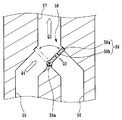
- FIG. 3 is a cross-sectional view showing the configuration of the resistance portion 59 and the switching portion 58.
- the resistance portion 59 of the present embodiment has a valve portion 59a that advances into one of the first flow path 55 and the second flow path 56 and makes the cross-sectional area of one of the advanced flow paths smaller than the other flow path.
- the valve portion 59a is configured so as to reduce the cross-sectional area of one channel that has advanced, but does not block one channel.
- the valve part 59a is provided with an opening part 59b which is one or a plurality of through holes.
- the switching unit 58 includes a state in which the valve part 59a has advanced into the second flow path 56 (state shown in FIG. 3), a state in which the valve part 59a has advanced into the first flow path 55 (state shown in FIG. 4), and ,
- the valve portion 59a is movably supported.
- the switching unit 58 includes a support shaft portion 58a that supports the valve portion 59a so that the valve portion 59a rotates at a location where the first flow path 55 and the second flow path 56 meet.
- the valve portion 59a is rotated around the support shaft portion 58a, so that the valve portion 59a is positioned in the opening portion of the first flow path 55 opened in the merging portion 57 and the second flow opening in the merging portion 57. It moves between the state located in the opening of the path 56.
- the pipe resistance of the first flow path 55 is lower than the pipe resistance of the second flow path 56. Further, in a state where the valve portion 59 a has advanced into the second flow path 56, the pipe resistance of the first flow path 55 is higher than the pipe resistance of the second flow path 56.
- the flow rate of the first channel 55 is Q1 and the flow rate of the second channel 56 is Q2 when the suction unit 52 is operated under the condition of sucking the fluid at the flow rate Q3.
- the flow rate Q3 of the suction unit 52 is the flow rate of the fluid that the fluid supply device 50 sends out from the sending unit 51.
- the flow rate Q3 is the sum of the flow rate Q1 and the flow rate Q2, and the flow rate Q1 and the flow rate Q2 exceed zero.
- the flow rate Q1 is higher than the flow rate Q2 when the suction unit 52 is operated under the condition of sucking fluid at the flow rate Q3.
- the flow rate Q1 is smaller than the flow rate Q2 when the suction unit 52 is operated under the condition of sucking fluid at the flow rate Q3.
- the pipe resistance of the second flow path 56 in the absence is substantially the same.
- the ratio of the flow rate Q1 to the flow rate Q2 in the flow rate Q3. Is simply reversed. Specifically, when the ratio of the flow rate Q1 to the flow rate Q2 in the flow rate Q3 is X: 1 in a state where the valve portion 59a has advanced into the second flow path 56 (here, X> 1), the valve In a state where the portion 59a has advanced into the first flow path 55, the ratio of the flow rate Q1 and the flow rate Q2 is 1: X.
- the fluid supply device 50 includes a flow rate detection unit 60 that measures the flow rate of the fluid delivered from the delivery unit 51.
- the fluid supply device 50 calculates the volume of the fluid delivered from the delivery unit 51 based on the detection result of the flow rate detection unit 60.
- the fluid supply device 50 may not include the flow rate detection unit 60.
- the control unit 5 of the endoscope reprocessor 1 calculates the volume of the fluid sent from the fluid supply device 50 based on the detection result of the flow rate detection unit, and sends out a predetermined volume of fluid. Thus, the operation of the fluid supply device 50 is controlled.
- the fluid supply apparatus 50 sucks the fluid from the first container 61a and the second container 61b connected to the first connection part 53 and the second connection part 54, and has a predetermined volume of the fluid. Is sent from the sending unit 51.
- the fluid supply device 50 moves the valve portion 59a of the resistance portion 59 by the switching portion 58, so that when the fluid of a predetermined volume is sent out, the volume of the fluid sucked out from the first container 61a is the second container. It is possible to switch between a state in which the volume of the fluid sucked out from 61b is larger and a state in which the volume of the fluid sucked out from the first container 61a is smaller than the volume of the fluid sucked out from the second container 61b.
- 5 to 7 are tables for explaining the operation of the body supply device 50.
- the fluid supply device 50 includes the flow rate Q1 of the first flow path 55 and the flow rate Q2 of the second flow path 56 that occupy the flow rate Q3 of the fluid delivered from the delivery unit 51 by the resistance unit 59 and the switching unit 58. It is assumed that the ratio can be switched between a state of 3: 1 and a state of 1: 3. And an unused container stores the liquid of the volume 5 times the volume of the fluid which the fluid supply apparatus 50 sends out by one delivery operation
- the number of executions of the delivery operation after connecting the unused first container 61a and second container 61b to the fluid supply apparatus 50 is shown as N.
- the column A indicates the remaining amount of fluid stored in the first container 61a after the Nth fluid delivery operation is completed.
- the column B shows the remaining amount of fluid stored in the second container 61b after the Nth fluid delivery operation has been completed.
- each of the unused first container 61a and second container 61b stores 20 volumes (units are indefinite) of liquid
- the fluid supply device 50 is Four volumes of fluid are delivered by the delivery operation.
- the valve part 59 a has advanced into the second flow path 56, and the flow rate Q1 of the first flow path 55 and the second flow path occupying the flow rate Q3 of the fluid sent from the delivery part 51 In this state, the ratio of the flow rate Q2 to 56 is 3: 1.
- both the first container 61a and the second container 61b become empty. Then, the first container 61a communicating with the first flow path 55 having a lower pipe resistance than the second flow path 56 becomes empty before the second container 61b.
- 3 volumes of liquid are sucked out from the first container 61a, and 1 volume of liquid is sucked out from the second container 61b.
- the first container 61a is empty, and in the seventh to tenth delivery operations, the fluid is sucked out only from the second container 61b.
- the fluid supply device 50 provides a difference between the flow rate Q1 of the first flow path 55 and the flow rate Q2 of the second flow path 56 that occupy the flow rate Q3 of the fluid sent from the delivery unit 51.
- the fluid stored in one of the pair of containers (61a, 61b) to be connected is consumed before the other. Since the fluid can be sucked out from the other container even after one of the containers is emptied, the fluid supply device 50 can execute the fluid feeding operation until the other container is emptied. Therefore, if one of the containers is replaced with an unused one by the user between the time when one container is emptied and the time when the other container is emptied, the fluid supply device 50 delivers the fluid. The operation can be continued and executed repeatedly.
- the first container 61a is replaced with a new unused one by the user during the period from the completion of the sixth fluid delivery operation to the completion of the tenth fluid delivery operation. If this is done, there is no time for the fluid supply device 50 to stop in a state where the fluid cannot be sucked out of the container and the delivery operation cannot be completed.
- FIG. 6 shows a case where, in the example shown in FIG. 5, the first container 61a is replaced with a new unused one by the user when the ninth fluid delivery operation is completed.
- the remaining amount of the first container 61a before the execution of the tenth fluid delivery operation is 20 volumes
- the remaining amount of the second container 61b is 4 volumes.
- the user operates the switching unit 58 so that the valve unit 59a of the resistance unit 59 has advanced into the first flow path 56. Therefore, in the example shown in FIG. 6, the ratio of the flow rate Q1 of the first flow path 55 and the flow rate Q2 of the second flow path 56 occupying the flow rate Q3 of the fluid delivered from the delivery unit 51 is 1: 3.
- the second container 61b communicating with the second flow path 56 having a lower pipe resistance than the first flow path 55 is emptied earlier than the first container 61a.
- the second container 61b is newly unused by the user during the period from the completion of the tenth fluid delivery operation to the completion of the fifteenth fluid delivery operation. Therefore, there is no time for the fluid supply device 50 to stop in a state where the fluid cannot be sucked out of the container and the delivery operation cannot be completed.
- FIG. 7 shows a case where the second container 61b is replaced with a new unused one by the user when the thirteenth fluid delivery operation is completed in the example shown in FIG.
- the remaining amount of the first container 61a is 5 volumes and the remaining amount of the second container 61b is 20 volumes before execution of the 14th fluid delivery operation.
- the user operates the switching unit 58 so that the valve unit 59a of the resistance unit 59 has advanced into the second flow path 55. Therefore, in the example shown in FIG. 7, the ratio of the flow rate Q1 of the first flow path 55 and the flow rate Q2 of the second flow path 56 occupying the flow rate Q3 of the fluid delivered from the delivery unit 51 is 3: 1.
- the first container 61a communicating with the first flow path 55 having a lower pipe resistance than the second flow path 56 is emptied earlier than the second container 61b.
- the second container 61b is newly unused by the user during the period from the completion of the 15th fluid delivery operation to the completion of the 20th fluid delivery operation. Therefore, there is no time for the fluid supply device 50 to stop in a state where the fluid cannot be sucked out of the container and the delivery operation cannot be completed.
- the fluid supply device 50 has a pair of connected first parts when the fluid delivery operation from the delivery unit 51 is repeated. By consuming the fluid stored in one of the first container 61a and the second container 61b before the other, one empty container can be replaced without stopping the repeated execution of the delivery operation. A period can be created.
- the fluid supply device 50 can continue the fluid delivery operation. For this reason, according to the fluid supply apparatus 50 of this embodiment, generation
- the endoscope reprocessor 1 including such a fluid supply device 50 can prevent the occurrence of time during which the regeneration process is stopped due to a lack of fluid in the container.
- the resistance portion 59 and the switching portion 58 of the fluid supply device 50 rotate the valve portion 59a having one or a plurality of openings 59b to thereby turn the first flow path 55.
- the structure of the resistance part 59 and the switching part 58 is not restricted to this embodiment.
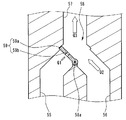
- FIG. 8 is a cross-sectional view showing a first modification of the resistance portion 59 and the switching portion 58.
- the valve portion 59 a of the resistance portion 59 is a plate-like or columnar member that advances into one of the first flow path 55 and the second flow path 56.
- the valve portion 59a advances into the first flow path 55 or the second flow path 56, thereby not closing the flow path and reducing the cross-sectional area of the flow path.
- the valve portion 59 a is supported by the switching portion 58, a position protruding into the first flow channel 55 from the side wall surface of the first flow channel 55, and the second flow channel 56 from the side wall surface of the second flow channel 56. It moves linearly between the position protruding to
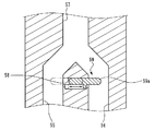
- FIG. 9 is a cross-sectional view showing a first modification of the resistance portion 59 and the switching portion 58.
- the resistance portion 59 includes deformation portions 59 c and 56 d made of a flexible material provided on the side walls of the first flow path 55 and the second flow path 56, and deformation.
- a pressing portion 59e that presses one of the portions 59c and 59d from the outside to the inside of the first channel 55 and the second channel 56.
- the pressing portion 59e is supported by the switching portion 58, and a position where the deforming portion 59c is pressed from the outside to the inside of the first channel 55 and the deforming portion 59c from the outside of the second channel 56 to the inside. And the position where it is pressed.
- one of the deformed portions 59c and 56d is advanced into one flow channel by pressing by the pressing portion 59e, whereby one of the first flow channel 55 and the second flow channel 56 is flowed. Is made smaller than the other channel.
Landscapes
- Health & Medical Sciences (AREA)
- Life Sciences & Earth Sciences (AREA)
- Engineering & Computer Science (AREA)
- Surgery (AREA)
- Public Health (AREA)
- General Engineering & Computer Science (AREA)
- Veterinary Medicine (AREA)
- Animal Behavior & Ethology (AREA)
- General Health & Medical Sciences (AREA)
- Mechanical Engineering (AREA)
- Physics & Mathematics (AREA)
- Radiology & Medical Imaging (AREA)
- Molecular Biology (AREA)
- Biophysics (AREA)
- Nuclear Medicine, Radiotherapy & Molecular Imaging (AREA)
- Optics & Photonics (AREA)
- Pathology (AREA)
- Medical Informatics (AREA)
- Heart & Thoracic Surgery (AREA)
- Biomedical Technology (AREA)
- Chemical Kinetics & Catalysis (AREA)
- Epidemiology (AREA)
- General Chemical & Material Sciences (AREA)
- Chemical & Material Sciences (AREA)
- Endoscopes (AREA)
Abstract
Le dispositif de distribution de fluide selon la présente invention comprend : une première partie de raccordement et une deuxième partie de raccordement pour raccorder un premier récipient et un deuxième récipient dans lesquels un fluide est stocké ; un premier canal d'écoulement communiquant avec la première partie de raccordement ; un deuxième canal d'écoulement communiquant avec la deuxième partie de raccordement ; une partie de fusion dans laquelle le premier canal d'écoulement et le deuxième canal d'écoulement fusionnent ; une partie d'aspiration pour aspirer un fluide depuis la partie de fusion et distribuer le fluide depuis une partie de distribution ; une partie de résistance pour générer une différence de résistance de canalisation de sorte que le débit de chacun du premier canal d'écoulement et du deuxième canal d'écoulement pendant le fonctionnement de la partie d'aspiration soit supérieur à zéro, la résistance de canalisation de l'un du premier canal d'écoulement et du deuxième canal d'écoulement étant supérieure à la résistance de canalisation de l'autre ; et une partie de commutation pour commuter la différence de résistance de canalisation entre un niveau élevé et un niveau bas dans le premier canal d'écoulement et le deuxième canal d'écoulement, la partie de commutation étant raccordée à la partie de résistance.
Priority Applications (2)
| Application Number | Priority Date | Filing Date | Title |
|---|---|---|---|
| JP2017506436A JP6138398B1 (ja) | 2016-02-03 | 2016-11-10 | 流体供給装置および内視鏡リプロセッサ |
| US15/646,167 US10034602B2 (en) | 2016-02-03 | 2017-07-11 | Fluid feeding apparatus and endoscope reprocessor |
Applications Claiming Priority (2)
| Application Number | Priority Date | Filing Date | Title |
|---|---|---|---|
| JP2016-019001 | 2016-02-03 | ||
| JP2016019001 | 2016-02-03 |
Related Child Applications (1)
| Application Number | Title | Priority Date | Filing Date |
|---|---|---|---|
| US15/646,167 Continuation US10034602B2 (en) | 2016-02-03 | 2017-07-11 | Fluid feeding apparatus and endoscope reprocessor |
Publications (1)
| Publication Number | Publication Date |
|---|---|
| WO2017134891A1 true WO2017134891A1 (fr) | 2017-08-10 |
Family
ID=59499657
Family Applications (1)
| Application Number | Title | Priority Date | Filing Date |
|---|---|---|---|
| PCT/JP2016/083426 Ceased WO2017134891A1 (fr) | 2016-02-03 | 2016-11-10 | Dispositif de distribution de fluide et dispositif de retraitement d'endoscope |
Country Status (2)
| Country | Link |
|---|---|
| US (1) | US10034602B2 (fr) |
| WO (1) | WO2017134891A1 (fr) |
Families Citing this family (2)
| Publication number | Priority date | Publication date | Assignee | Title |
|---|---|---|---|---|
| EP4353185A3 (fr) * | 2018-08-30 | 2024-09-25 | ASP Global Manufacturing GmbH | Appareil et procédé pour remplir et purger de manière asynchrone des canaux d'endoscope simultanément |
| CA3060954A1 (fr) * | 2018-11-06 | 2020-05-06 | LMC Industrial Contractors, Inc. | Restauration de sections de tuyau degage |
Citations (2)
| Publication number | Priority date | Publication date | Assignee | Title |
|---|---|---|---|---|
| JPS60120998U (ja) * | 1984-01-24 | 1985-08-15 | 三洋電機株式会社 | 液体供給装置 |
| JP2010035620A (ja) * | 2008-07-31 | 2010-02-18 | Olympus Medical Systems Corp | 内視鏡洗浄消毒装置 |
Family Cites Families (1)
| Publication number | Priority date | Publication date | Assignee | Title |
|---|---|---|---|---|
| JP4504249B2 (ja) | 2005-05-16 | 2010-07-14 | オリンパスメディカルシステムズ株式会社 | 内視鏡洗滌消毒装置 |
-
2016
- 2016-11-10 WO PCT/JP2016/083426 patent/WO2017134891A1/fr not_active Ceased
-
2017
- 2017-07-11 US US15/646,167 patent/US10034602B2/en active Active
Patent Citations (2)
| Publication number | Priority date | Publication date | Assignee | Title |
|---|---|---|---|---|
| JPS60120998U (ja) * | 1984-01-24 | 1985-08-15 | 三洋電機株式会社 | 液体供給装置 |
| JP2010035620A (ja) * | 2008-07-31 | 2010-02-18 | Olympus Medical Systems Corp | 内視鏡洗浄消毒装置 |
Also Published As
| Publication number | Publication date |
|---|---|
| US10034602B2 (en) | 2018-07-31 |
| US20170303777A1 (en) | 2017-10-26 |
Similar Documents
| Publication | Publication Date | Title |
|---|---|---|
| CN104902804B (zh) | 内窥镜清洗消毒装置、内窥镜的清洗方法 | |
| JP2007533437A (ja) | 洗浄方法および洗浄装置 | |
| US9968973B2 (en) | Endoscope reprocessor | |
| WO2017134891A1 (fr) | Dispositif de distribution de fluide et dispositif de retraitement d'endoscope | |
| JP6038412B1 (ja) | 内視鏡リプロセッサの制御方法 | |
| JP6138398B1 (ja) | 流体供給装置および内視鏡リプロセッサ | |
| JP2016135190A (ja) | 内視鏡リプロセッサ | |
| JP6599757B2 (ja) | 内視鏡リプロセッサ | |
| US20230355350A1 (en) | Reprocessor for medical equipment and bottle | |
| AU2023299263B2 (en) | Tube reservoir chemical dosing system | |
| CN106163376B (zh) | 内窥镜清洗消毒机 | |
| JP6726540B2 (ja) | 内視鏡リプロセッサ | |
| JP6655421B2 (ja) | 内視鏡リプロセッサ | |
| JP2019025287A (ja) | 廃液吸引装置、廃液吸引方法、及び、廃液吸引装置の洗浄方法 | |
| CN111050630B (zh) | 内窥镜再生处理器的控制方法及内窥镜再生处理器 | |
| KR100947431B1 (ko) | 오존 손 소독기 | |
| JP6472114B1 (ja) | 内視鏡リプロセッサ | |
| JP6854609B2 (ja) | 内視鏡リプロセッサ | |
| JP6465331B1 (ja) | 内視鏡リプロセッサの制御方法および内視鏡リプロセッサ | |
| JP2017055893A (ja) | 内視鏡リプロセッサ | |
| JP6609851B2 (ja) | 内視鏡リプロセッサ | |
| JP2018143538A (ja) | 付属品ケース、付属品ケースシステムおよび内視鏡リプロセッサ | |
| WO2019087473A1 (fr) | Dispositif de retraitement d'endoscope |
Legal Events
| Date | Code | Title | Description |
|---|---|---|---|
| ENP | Entry into the national phase |
Ref document number: 2017506436 Country of ref document: JP Kind code of ref document: A |
|
| 121 | Ep: the epo has been informed by wipo that ep was designated in this application |
Ref document number: 16889374 Country of ref document: EP Kind code of ref document: A1 |
|
| NENP | Non-entry into the national phase |
Ref country code: DE |
|
| 122 | Ep: pct application non-entry in european phase |
Ref document number: 16889374 Country of ref document: EP Kind code of ref document: A1 |