WO2017134982A1 - Dispositif d'imagerie - Google Patents
Dispositif d'imagerie Download PDFInfo
- Publication number
- WO2017134982A1 WO2017134982A1 PCT/JP2017/000362 JP2017000362W WO2017134982A1 WO 2017134982 A1 WO2017134982 A1 WO 2017134982A1 JP 2017000362 W JP2017000362 W JP 2017000362W WO 2017134982 A1 WO2017134982 A1 WO 2017134982A1
- Authority
- WO
- WIPO (PCT)
- Prior art keywords
- area
- object detection
- distance
- image
- imaging
- Prior art date
- Legal status (The legal status is an assumption and is not a legal conclusion. Google has not performed a legal analysis and makes no representation as to the accuracy of the status listed.)
- Ceased
Links
Images



Classifications
-
- G—PHYSICS
- G08—SIGNALLING
- G08G—TRAFFIC CONTROL SYSTEMS
- G08G1/00—Traffic control systems for road vehicles
- G08G1/16—Anti-collision systems
- G08G1/166—Anti-collision systems for active traffic, e.g. moving vehicles, pedestrians, bikes
-
- G—PHYSICS
- G01—MEASURING; TESTING
- G01C—MEASURING DISTANCES, LEVELS OR BEARINGS; SURVEYING; NAVIGATION; GYROSCOPIC INSTRUMENTS; PHOTOGRAMMETRY OR VIDEOGRAMMETRY
- G01C3/00—Measuring distances in line of sight; Optical rangefinders
- G01C3/02—Details
- G01C3/06—Use of electric means to obtain final indication
-
- G—PHYSICS
- G06—COMPUTING OR CALCULATING; COUNTING
- G06T—IMAGE DATA PROCESSING OR GENERATION, IN GENERAL
- G06T1/00—General purpose image data processing
-
- G—PHYSICS
- G06—COMPUTING OR CALCULATING; COUNTING
- G06T—IMAGE DATA PROCESSING OR GENERATION, IN GENERAL
- G06T7/00—Image analysis
- G06T7/50—Depth or shape recovery
- G06T7/55—Depth or shape recovery from multiple images
- G06T7/593—Depth or shape recovery from multiple images from stereo images
-
- G—PHYSICS
- G06—COMPUTING OR CALCULATING; COUNTING
- G06V—IMAGE OR VIDEO RECOGNITION OR UNDERSTANDING
- G06V20/00—Scenes; Scene-specific elements
- G06V20/50—Context or environment of the image
- G06V20/56—Context or environment of the image exterior to a vehicle by using sensors mounted on the vehicle
- G06V20/58—Recognition of moving objects or obstacles, e.g. vehicles or pedestrians; Recognition of traffic objects, e.g. traffic signs, traffic lights or roads
- G06V20/582—Recognition of moving objects or obstacles, e.g. vehicles or pedestrians; Recognition of traffic objects, e.g. traffic signs, traffic lights or roads of traffic signs
-
- G—PHYSICS
- G06—COMPUTING OR CALCULATING; COUNTING
- G06V—IMAGE OR VIDEO RECOGNITION OR UNDERSTANDING
- G06V40/00—Recognition of biometric, human-related or animal-related patterns in image or video data
- G06V40/20—Movements or behaviour, e.g. gesture recognition
- G06V40/23—Recognition of whole body movements, e.g. for sport training
-
- H—ELECTRICITY
- H04—ELECTRIC COMMUNICATION TECHNIQUE
- H04N—PICTORIAL COMMUNICATION, e.g. TELEVISION
- H04N23/00—Cameras or camera modules comprising electronic image sensors; Control thereof
-
- H—ELECTRICITY
- H04—ELECTRIC COMMUNICATION TECHNIQUE
- H04N—PICTORIAL COMMUNICATION, e.g. TELEVISION
- H04N7/00—Television systems
- H04N7/18—Closed-circuit television [CCTV] systems, i.e. systems in which the video signal is not broadcast
-
- G—PHYSICS
- G01—MEASURING; TESTING
- G01C—MEASURING DISTANCES, LEVELS OR BEARINGS; SURVEYING; NAVIGATION; GYROSCOPIC INSTRUMENTS; PHOTOGRAMMETRY OR VIDEOGRAMMETRY
- G01C3/00—Measuring distances in line of sight; Optical rangefinders
- G01C3/10—Measuring distances in line of sight; Optical rangefinders using a parallactic triangle with variable angles and a base of fixed length in the observation station, e.g. in the instrument
- G01C3/14—Measuring distances in line of sight; Optical rangefinders using a parallactic triangle with variable angles and a base of fixed length in the observation station, e.g. in the instrument with binocular observation at a single point, e.g. stereoscopic type
Definitions
- the present invention relates to an imaging apparatus.
- Patent Document 1 proposes a method using both distance detection using a stereo camera and distance detection using a monocular camera.
- Patent Document 1 the distance between the vehicle and the object is detected by detecting the distance by a monocular camera, and the position of the object is tracked while suppressing the calculation amount. It is stated that when the distance becomes equal to or less than a preset switching distance, the distance is detected by a stereo camera and the position of an object approaching the vehicle is recognized with higher accuracy.
- Patent Document 1 states that while the amount of calculation is smaller with a monocular camera, the detection accuracy is higher with a stereo camera.
- Patent Document 1 can reduce the calculation load when there is one object to be detected.
- the objects to be detected usually exist both in the distance and in the vicinity, there are cases where it is necessary to perform monocular processing and stereo processing for each of the plurality of objects, thereby efficiently reducing the computation load. There is a risk that it will not be possible.
- an object of the present invention is to provide an imaging apparatus that can achieve both improvement in detection accuracy and reduction in calculation load even when there are a plurality of objects to be detected.
- the present invention is an imaging apparatus having a plurality of imaging units, wherein the first region is a first region that is a part of a common imaging region common to each captured image captured by the plurality of imaging units. Is calculated based on the parallax between the plurality of captured images, and includes the other region different from the first region in the captured image. In the two areas, the distance of the image elements in the partial area is calculated based on the parallax between the plurality of images with respect to the partial area that is a part of the second area.
- the present invention can achieve both improvement in detection accuracy and reduction in computation load even when there are a plurality of objects to be detected.
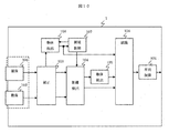
- FIG. 1 is a diagram showing a configuration of an embodiment of an imaging apparatus of the present invention.
- Reference numeral 1 denotes an imaging apparatus according to the present embodiment, which is mounted in front of a vehicle, for example, and is configured as a part of a safety system that assists the driver by recognizing signals, signs, obstacles, and the like.
- Reference numerals 101 and 102 denote image pickup units, and optical lenses are attached to the image sensor. These image capturing units repeatedly capture one image at a predetermined timing, and output the captured image.
- the imaging unit 101 and the imaging unit 102 are installed at a predetermined distance from each other to the left and right, and the distance to the subject can be calculated from a shift between images captured by the imaging unit 101 and the imaging unit 102, that is, parallax.
- the imaging units 101 and 102 may be housed together in a housing separate from other components.
- the imaging units 101 and 102 may be housed in separate housings and attached to the vehicle.
- the image signal may be connected by a connection cable (not shown).
- a transmission method using a differential transmission path of an LVDS (Low Voltage Differential Signaling) method there is a transmission method using a differential transmission path of an LVDS (Low Voltage Differential Signaling) method.
- LVDS Low Voltage Differential Signaling
- the image sensors of the imaging unit 101 and the imaging unit 102 as color image sensors, it is possible to acquire color information of the captured image.
- Reference numeral 103 denotes an image correction unit that takes in images from the imaging units 101 and 102, corrects them with correction values measured in advance so as to match the luminance of the respective images, and further corrects image distortion by the lens and captures images. This is also corrected with a correction value measured in advance so as to align the horizontal positions of the images of the units 101 and 102, and stored in the image memory.
- the correction value is measured in the manufacturing process of the imaging device. For each device before applying the correction value, capture a specific subject, and correct the luminance correction value for each pixel so that the luminance of the acquired image is uniform, and cancel the lens distortion for each pixel so that the image becomes horizontal.
- a geometric correction value is obtained and stored as a correction table in a nonvolatile memory (not shown) for each device, for example.
- An area control unit 104 designates an area of an image whose distance is detected by a distance detection unit 105, which will be described later, and outputs the area to the distance detection unit 105. Further, an image of an image whose object is detected by an object detection unit 107, which will be described later. A region is designated, output to the object detection unit 107, and a result detected by the object detection unit 107 is received. That is, the area of the image that should be distance-detected is designated in the distance detector 105, and the area of the image that should be detected in the object is designated in the object detector 107.
- Reference numeral 105 denotes a distance detection unit that detects an object distance by inputting an image from the image correction unit 103. For example, there are the following methods for detecting the distance.
- the distance detection unit 105 takes in the image from the image correction unit 103 and calculates the parallax. As described above, since the image capturing unit 101 and the image capturing unit 102 are installed to be separated from each other at a predetermined distance, the captured image has parallax. A so-called stereo process for calculating the parallax is performed. As a parallax calculation method, for example, there is a block matching method.
- the distance detection unit 105 performs distance detection on the region of the image designated by the region control unit 104 among the images from the image correction selection unit 103, for example.
- an area where the same subject on the image of the imaging unit 102 corresponding to a block area of a predetermined size cut out from the image of the imaging unit 101 is searched in the horizontal direction.
- the difference between the positions of the matching block areas in the imaging unit 101 and the imaging unit 102 is parallax.
- the distance in the real environment of the object shown in the block area can be obtained.
- a block area is used as an image element whose distance is to be obtained.
- a position where the sum of luminance differences of pixels in the block region is reduced is set as a parallax.
- the distance is obtained from the lens focal length of the imaging unit 101 and the imaging unit 102, the distance between the imaging unit 101 and the imaging unit 102, the parallax obtained above, and the pixel pitch of the imaging sensor.
- the method for calculating the distance is not limited to this.
- the image element that is a target for obtaining the distance is not limited to the above-described block region, and individual pixels constituting the imaging sensor may be employed.
- the 106 is an object detection unit based on the distance information, and detects an object based on the distance information of the area specified by the area control unit 104 obtained by the distance detection unit 105. For example, when distance information indicating almost the same distance exists in the vicinity, the objects are detected by grouping them as one set, and the group is regarded as an object when the size of the group exceeds a certain value. . And it detects that it is a vehicle or a pedestrian, for example based on the magnitude
- the object detection unit 106 captures an image of either the image capturing unit 101 or the image capturing unit 102, and detects an assumed traffic signal, a road sign, or the like in the captured image.
- this detection method for example, there is a method of detecting an object such as a traffic signal or a road sign from the similarity between the luminance distribution and edge shape information in the image and the pattern data held as reference data. . Thereby, the object in the image and its position on the screen can be grasped.
- the object detection unit 107 outputs the detection result to the region control unit 104, and the region control unit 104 designates a region for distance detection to the distance detection unit 105 based on the result.
- the distance detection unit 105 performs the above-described distance detection for a specified region in the image from the correction unit 103 and outputs the result to the recognition unit 108 described later. Thereby, it becomes possible to limit the area
- the 108 is a recognition unit that receives the detection results of the object detection unit 106, the object detection unit 107, and the distance detection unit 105, recognizes the object on the image, and outputs information of the recognition result to the outside of the imaging apparatus 1.
- the imaging units 101 and 102, the image correction unit 103, and the distance detection unit 105 in the dotted frame 11 are configured by electronic circuits, and other components are realized by software processing using a microcomputer (not shown). Is done.
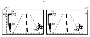
- FIG. 2 is a diagram showing an example of a captured image captured by an embodiment of the imaging apparatus of the present invention.
- reference numeral 1001 denotes a picked-up image picked up by the image pickup unit 101 and corrected by the correction unit 103
- reference numeral 1002 denotes a picked-up image picked up by the image pickup unit 102 and corrected by the correction unit 103
- Reference numerals 202, 203, and 204 denote subjects.
- Reference numerals 201 and 208 denote common imaging areas that are areas that are commonly imaged among the captured image 1001 and the captured image 1002. As described above, there is a shift in the area that is commonly captured between the captured image 1001 and the captured image 1002, and the distance of the subject is calculated based on the shift amount, that is, the parallax.
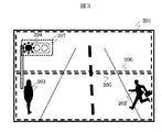
- FIG. 3 is a diagram illustrating an example of a captured image and area control captured by an embodiment of the imaging apparatus of the present invention.
- 201 indicates a region that is imaged in common with the image captured by the imaging unit 102 as described above, among the captured images captured by the imaging unit 101 and corrected by the correction unit 103.
- the processing region 205 and 206 are processing regions designated by the region control unit 104 in the captured image 201.
- the processing region 205 is processed by the distance detection unit 105 and then processed by the object detection unit 106.
- This is a processing area where object detection is performed. That is, the processing area 205 is a part of the common imaging area (for convenience, the first area). In this first area, the image in the partial area extends over the entire first area. The distance about the element is calculated based on the parallax between the plurality of captured images.
- the processing area 206 is an image area in which, after the object detection process is performed in the object detection 107, an area is further specified from the result, and the distance detection process is performed in the distance detection unit 105.
- the processing area 205 is an area including another area different from the first area (for convenience, the second area).
- the partial area is a part of the second area.
- the distance for the image element in the partial region is calculated based on the parallax between the plurality of images. The first area, the other area, the second area, and the partial area will be described later with reference to FIGS.
- the 207 is a processing area designated by the area control unit 104 based on the result of detecting the object in the object detection 107 in the processing area 206.
- the traffic signal 204 is detected by the object detection unit 107 from the processing region 206, the processing region 207 including the traffic signal is specified by the region control unit 104, and the distance detection processing is performed in the distance detection unit 105 for this processing region 207. Is done.
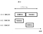
- FIG. 4 is a diagram showing the processing timing of an embodiment of the imaging apparatus of the present invention.
- (3-1) is the processing timing of the processing area 205
- (3-2) is the processing timing of the processing area 206
- (3-3) is the processing timing of the processing area 207 in the processing area 206. Show.
- the distance detection unit 105 performs distance detection processing on the processing region 205, and then the object detection unit 106 performs object detection.
- object detection is performed in the object detection 107 for the processing region 206.
- the distance detection unit 105 determines the processing region 207 that is the processing region designated by the region control unit 104 based on the result detected by the object detection unit 107 in (3-2). A detection process is performed.
- the distance detection process in the distance detection unit 105 is performed only for the specified necessary processing area, the entire area of the captured image is not processed, and the processing load can be reduced. Further, since the operation of the distance detection unit 105 can be time-divisionally processed by the processing of (3-1) and the processing of (3-3), for example, with one piece of hardware that realizes the distance detection unit 105 Since processing is possible, the circuit scale can be reduced. Further, the process (3-1) and the processes (3-2) to (3-3) can be performed in parallel. Further, these processes are performed in a period of one frame (that is, a processing cycle) that is an imaging interval of the imaging units 101 and 102, and a detection process suitable for various objects is performed by switching a processing area designated for each frame. Is possible.
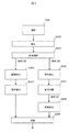
- FIG. 5 is a diagram showing a processing flow of an embodiment of the imaging apparatus of the present invention.
- an image is captured by the imaging units 101 and 102 (S401: S represents a step).
- Each captured image is subjected to luminance correction, lens distortion correction, and horizontal alignment as described above by the image correction unit 103 (S402).
- the area control unit 104 designates a processing area of an image to be processed subsequently (S403).
- the distance is detected by the distance detection unit 105 using the images captured by the imaging units 101 and 102 (S404). Based on the obtained distance information, the object detection unit 106 detects an object (S405).
- the object detection unit 107 detects an object in the processing region 206 using one of the images of the imaging units 101 and 102 (S406).
- This processing is also referred to as monocular processing.
- an object is detected by a technique such as pattern matching.
- the region control unit 104 designates a processing region for which distance detection is to be performed (S407). Then, the distance of the area 207 is detected by the distance detection unit 105 using the images captured by the imaging units 101 and 102 (S408).
- the recognition unit 108 performs object recognition processing based on the detection result of the object in each processing region, and outputs the recognition result (S409). These processes are repeated for each frame, for example.
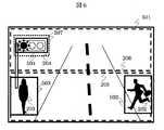
- FIG. 6 is a diagram showing an example of a captured image and a recognition result in an embodiment of the imaging apparatus of the present invention.
- Reference numeral 501 denotes an image picked up by the image pickup unit 101 at a certain point in time, and the image pickup unit 102 picks up and acquires a substantially similar image.
- Reference numerals 502, 503, and 504 denote object recognition results, and the frame in the image is not shown in the captured image but explicitly shows the recognized moving object.
- the traffic signals 204 of the pedestrian 202 and pedestrian 203 detected from the processing area 205 and the processing area 207 detected from the processing area 206 are detected.
- object recognition can be realized over the entire captured image.
- processing area 205 corresponds to the first area described above.
- the processing area 206 corresponds to the second area described above and also corresponds to the other area described above. In this example, the second area and the other area are the same area.
- the processing area 207 corresponds to the partial area described above.
- the processing area of the captured image is divided, and for the processing area 205, the distance of the subject is detected by the two imaging units, the object is detected based on the result, and the processing area 206 is An object is detected from an image captured by one imaging unit, a processing region is further specified based on the detection result, and the distance between the objects in the processing region is detected by the two imaging units.
- FIG. 7 is a diagram showing an example of region setting in an embodiment of the imaging apparatus of the present invention.
- reference numeral 201 denotes a common imaging area for images taken by the imaging units 101 and 102.
- a processing region 602 detects a distance by the distance detection unit 105 using the images captured by the imaging units 101 and 102 as described above, and detects an object by the object detection unit 106 based on the obtained distance information.
- 603 detects an object in the processing region 603 by the object detection unit 107 using one of the images of the imaging units 101 and 102, and detects the distance by the region control unit 104 based on the obtained detection result.
- a processing region in which a processing region to be specified is a processing region in which a distance is detected by the distance detection unit 105 using images captured by the imaging units 101 and 102.
- the area control unit 104 controls the positions and sizes of the processing areas.
- the processing area 602 is designated below the common imaging area 201, and the processing area 603 is set above.
- the processing area is designated in this way, as described above, when detecting a pedestrian or a vehicle ahead of the vehicle in the processing area 602, it can be detected with high accuracy, and further, a traffic signal or a road sign can be detected in the processing area 603.
- the processing area 602 corresponds to the first area described above.
- the processing area 603 corresponds to the other area described above and also corresponds to the second area described above. In this example, the other area and the second area are the same area.
- the processing area 603 is designated below the common imaging area 201, and the processing area 602 is set above.
- the processing area 602 corresponds to the first area described above.
- the processing area 603 corresponds to the other area described above and also corresponds to the second area described above. In this example, the other area and the second area are the same area.
- the processing area 602 and the processing area 603 so as to partially overlap as shown in FIGS. 7 (3) and (4).
- the processing area 602 corresponds to the first area described above.
- the processing area 603a corresponds to the other area described above, and the processing area 603 corresponds to the second area described above.
- the other area is an area excluding an overlapping area with the first area in the second area.
- Area selection can be switched in units of frames that are imaging units.
- it is possible to further limit the processing region by further restricting the processing region by moving the processing region in the steering direction of the vehicle and specifying it in accordance with the vertical and horizontal vibrations.
- the object detection process can be continued by designating the processing region 603 over the entire image region 201. It becomes possible.
- FIG. 8 is a schematic diagram of a current consumption waveform of the distance detection unit 105 during the distance detection operation in the embodiment of the imaging apparatus of the present invention.
- FIG. 8 (A) shows an operating current waveform when distance detection is performed by stereo processing over the entire region of the captured image regardless of the present invention, and power is consumed over the entire frame.
- FIG. 8B is a current waveform at the time of distance detection operation in one embodiment of the imaging apparatus of the present invention, and power is consumed at a limited timing within the frame as compared with FIG. Reduction of power consumption can be realized.
- FIG. 9 is a diagram showing another embodiment of area control in the imaging apparatus of the present invention.
- FIGS. 9A to 9D show the area designation for each frame.
- the size and position of the processing area 603 are designated by the area control unit 104, and the position is designated while being shifted for each frame. ing.
- the processing area of the object recognition processing by the object recognition unit 107 is narrowed, so that the processing load can be further reduced. Since the processing area 603 moves every frame, the entire area can be covered and is suitable for detecting an object that does not move, such as a traffic signal.
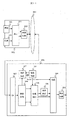
- FIG. 10 is a diagram showing the configuration of another embodiment of the imaging apparatus of the present invention.
- the imaging device 1 is mounted on a vehicle such as an automobile, and 801 in FIG. 10 is a vehicle control unit.
- the output of the recognition unit 108 is input to the vehicle control unit 801.
- the vehicle control unit 801 receives the recognition result by the recognition unit 108 and controls other devices (not shown) of the vehicle.
- Vehicle control includes lighting of warning lamps for drivers, detection of warning sounds, deceleration by brake braking, stop control, stop control, and tracking of preceding vehicles. These include throttle and brake control, and other steering angle controls for collision avoidance and lane keeping.
- the vehicle control information is output from the imaging device 1 to another device (not shown) via the in-vehicle network.
- FIG. 10 shows an example in which the vehicle control unit 801 is housed in the same housing as the imaging device 1, but the present invention is not limited to this, and the imaging units 101 and 102 may be separate housings as described above. .
- FIG. 11 is a diagram showing the configuration of still another embodiment of the imaging apparatus of the present invention.
- Reference numeral 901 denotes a network imaging unit
- reference numeral 903 denotes a LAN (Local Area Network)
- reference numeral 904 denotes a control unit.
- the network imaging unit 901 is connected to the control unit 904 via the LAN 903.
- Reference numeral 902 denotes an image compression / interface unit
- 905 denotes a network interface unit
- 906 denotes an image expansion unit.
- the image captured by the image capturing unit 101 and the image capturing unit 102 is subjected to brightness correction, lens distortion correction, and horizontal alignment in the image correction unit 103.
- the image compression / interface unit 902 compresses the image from the image correction unit 103 and transmits it to the LAN 903.
- an image compression method there is a method using an in-screen compression method in which compression is performed within one image without using temporal correlation of a plurality of images in order to reduce processing time. Also, the video compression encoding method may be selected and switched.
- the image compression / interface unit 902 generates compressed encoded data and transmits the data according to a predetermined network protocol.
- the image correction unit 103 performs processing in the previous stage of the image compression / interface unit 902 so as to correct the lens distortion and then compress the image. You may provide in the back
- the network interface unit 905 receives the compressed image data via the LAN 903.
- the compressed image data received by the network interface unit 905 of the control unit 904 is expanded to the original image by the image expansion unit 906, and the image of the processing area designated by the area control unit 104 is converted into the distance detection unit 104 and the object detection unit. 107 performs the above-described processing.
- the subsequent processing is as described above.
- the amount of processing on the imaging unit side can be reduced, the imaging unit side is lighter, the power consumption is reduced, and the housing is reduced. Therefore, it becomes possible to reduce the dimensional limitation on the vehicle installation.
- this invention is not limited to an above-described Example, Various modifications are included.
- the above-described embodiments have been described in detail for easy understanding of the present invention, and are not necessarily limited to those having all the configurations described.
- a part of the configuration of one embodiment can be replaced with the configuration of another embodiment, and the configuration of another embodiment can be added to the configuration of one embodiment.
- each of the above-described configurations may be configured such that a part or all of the configuration is configured by hardware, or is realized by executing a program by a processor.
- control lines and information lines indicate what is considered necessary for the explanation, and not all the control lines and information lines on the product are necessarily shown. Actually, it may be considered that almost all the components are connected to each other.
- SYMBOLS 1 ... Imaging device, 101-102 ... Imaging part, 103 ... Image correction part, 104 ... Area control part, 105 ... Distance detection part, 106 ... Moving body detection part, 107 ... Object detection part, 108 ... Recognition part, 201 ... Common Imaging region, 202 to 204 ... Subject, 205 to 207 ... Processing region, 602 to 603 ... Processing region, 801 ... Vehicle control unit, 901 ... Network imaging unit, 902 ... Image compression / interface unit, 903 ... LAN, 904 ... Control Reference numeral 905... Network interface part 906.
Landscapes
- Engineering & Computer Science (AREA)
- Physics & Mathematics (AREA)
- General Physics & Mathematics (AREA)
- Theoretical Computer Science (AREA)
- Multimedia (AREA)
- Electromagnetism (AREA)
- Radar, Positioning & Navigation (AREA)
- Remote Sensing (AREA)
- Computer Vision & Pattern Recognition (AREA)
- Signal Processing (AREA)
- Health & Medical Sciences (AREA)
- General Health & Medical Sciences (AREA)
- Psychiatry (AREA)
- Social Psychology (AREA)
- Human Computer Interaction (AREA)
- Traffic Control Systems (AREA)
- Image Processing (AREA)
- Measurement Of Optical Distance (AREA)
- Closed-Circuit Television Systems (AREA)
- Studio Devices (AREA)
- Image Analysis (AREA)
Abstract
La présente invention concerne un dispositif d'imagerie au moyen duquel une précision de détection améliorée et une charge de calcul réduite peuvent toutes deux être obtenues en même temps, même lorsqu'une pluralité d'objets faisant fonction de sujets de détection est présente. Afin d'atteindre cet objectif, la présente invention comprend: une première unité de traitement de détection d'objets dotée d'une pluralité d'unités d'imagerie, la première unité de traitement de détection d'objets effectuant un premier traitement de détection d'objets visant à détecter, par un traitement stéréoscopique, une distance pour chaque élément d'une pluralité d'éléments d'image dans une région partielle d'intérêt dans une image acquise par les unités d'imagerie, puis à extraire un groupe des éléments d'image sur la base des distances détectées et à détecter un objet; et une deuxième unité de traitement de détection d'objets servant à effectuer un deuxième traitement de détection d'objets pour détecter la distance de l'objet par un traitement stéréoscopique pour une région partielle d'une autre région d'intérêt dans l'image.
Priority Applications (3)
| Application Number | Priority Date | Filing Date | Title |
|---|---|---|---|
| CN201780006341.1A CN108496056B (zh) | 2016-02-04 | 2017-01-10 | 摄像装置 |
| EP17747146.3A EP3413015B1 (fr) | 2016-02-04 | 2017-01-10 | Dispositif d'imagerie |
| US16/066,274 US11650052B2 (en) | 2016-02-04 | 2017-01-10 | Imaging device |
Applications Claiming Priority (2)
| Application Number | Priority Date | Filing Date | Title |
|---|---|---|---|
| JP2016019401A JP6660751B2 (ja) | 2016-02-04 | 2016-02-04 | 撮像装置 |
| JP2016-019401 | 2016-02-04 |
Publications (1)
| Publication Number | Publication Date |
|---|---|
| WO2017134982A1 true WO2017134982A1 (fr) | 2017-08-10 |
Family
ID=59499505
Family Applications (1)
| Application Number | Title | Priority Date | Filing Date |
|---|---|---|---|
| PCT/JP2017/000362 Ceased WO2017134982A1 (fr) | 2016-02-04 | 2017-01-10 | Dispositif d'imagerie |
Country Status (5)
| Country | Link |
|---|---|
| US (1) | US11650052B2 (fr) |
| EP (1) | EP3413015B1 (fr) |
| JP (1) | JP6660751B2 (fr) |
| CN (1) | CN108496056B (fr) |
| WO (1) | WO2017134982A1 (fr) |
Cited By (1)
| Publication number | Priority date | Publication date | Assignee | Title |
|---|---|---|---|---|
| CN112470456A (zh) * | 2018-07-24 | 2021-03-09 | 株式会社东芝 | 铁路车辆用摄像系统 |
Families Citing this family (11)
| Publication number | Priority date | Publication date | Assignee | Title |
|---|---|---|---|---|
| WO2018086133A1 (fr) * | 2016-11-14 | 2018-05-17 | SZ DJI Technology Co., Ltd. | Procédés et systèmes de fusion sélective de capteurs |
| JP6841331B2 (ja) * | 2017-07-24 | 2021-03-10 | 富士通株式会社 | 車両駐車支援装置、車両駐車支援プログラム |
| JP7042185B2 (ja) * | 2018-07-27 | 2022-03-25 | 日立Astemo株式会社 | 距離算出装置 |
| JP7157330B2 (ja) * | 2018-11-27 | 2022-10-20 | 富士通株式会社 | 監視装置、監視方法および監視プログラム |
| JP7278846B2 (ja) | 2019-04-17 | 2023-05-22 | 日立Astemo株式会社 | 物体位置検出装置、走行制御システム、および走行制御方法 |
| JP7358890B2 (ja) * | 2019-10-01 | 2023-10-11 | 富士フイルムビジネスイノベーション株式会社 | 物体質感計測装置 |
| CN111422190B (zh) * | 2020-04-03 | 2021-08-31 | 北京四维智联科技有限公司 | 一种后装车机的前向碰撞预警方法及系统 |
| JP2021190848A (ja) * | 2020-05-29 | 2021-12-13 | ソニーセミコンダクタソリューションズ株式会社 | 検出装置、検出システム及び検出方法 |
| US11468688B2 (en) * | 2020-07-31 | 2022-10-11 | Toyota Motor Engineering & Manufacturing North America, Inc. | Vehicle sensor data sharing |
| US20220191385A1 (en) * | 2020-12-16 | 2022-06-16 | Irobot Corporation | Dynamic camera adjustments in a robotic vacuum cleaner |
| CN116524453B (zh) * | 2022-01-28 | 2026-03-13 | 本田技研工业株式会社 | 运动物体检测装置、方法及系统、以及存储介质 |
Citations (4)
| Publication number | Priority date | Publication date | Assignee | Title |
|---|---|---|---|---|
| JP2000331148A (ja) * | 1999-05-19 | 2000-11-30 | Nissan Motor Co Ltd | 障害物検出装置 |
| JP2006322795A (ja) * | 2005-05-18 | 2006-11-30 | Olympus Corp | 画像処理装置、画像処理方法および画像処理プログラム |
| JP2011191905A (ja) * | 2010-03-12 | 2011-09-29 | Hitachi Automotive Systems Ltd | ステレオカメラ装置 |
| JP2013058829A (ja) | 2011-09-07 | 2013-03-28 | Honda Motor Co Ltd | 車両周辺監視装置 |
Family Cites Families (10)
| Publication number | Priority date | Publication date | Assignee | Title |
|---|---|---|---|---|
| WO2006121088A1 (fr) | 2005-05-10 | 2006-11-16 | Olympus Corporation | Dispositif de traitement d’images, procede de traitement d’images et programme de traitement d’images |
| JP4856612B2 (ja) * | 2007-10-29 | 2012-01-18 | 富士重工業株式会社 | 物体検出装置 |
| JP5690688B2 (ja) | 2011-09-15 | 2015-03-25 | クラリオン株式会社 | 外界認識方法,装置,および車両システム |
| JP5587930B2 (ja) * | 2012-03-09 | 2014-09-10 | 日立オートモティブシステムズ株式会社 | 距離算出装置及び距離算出方法 |
| JP6313646B2 (ja) * | 2014-04-24 | 2018-04-18 | 日立オートモティブシステムズ株式会社 | 外界認識装置 |
| WO2016063545A1 (fr) * | 2014-10-24 | 2016-04-28 | 京セラ株式会社 | Appareil de caméra stéréo et véhicule comprenant un appareil de caméra stéréo |
| JP6606369B2 (ja) * | 2015-07-21 | 2019-11-13 | 株式会社Soken | 物体検出装置及び物体検出方法 |
| JP6825569B2 (ja) * | 2015-09-30 | 2021-02-03 | ソニー株式会社 | 信号処理装置、信号処理方法、およびプログラム |
| EP3392830B1 (fr) * | 2015-12-14 | 2023-09-06 | Ricoh Company, Ltd. | Dispositif de traitement d'images, dispositif de reconnaissance d'objets, système de commande d'appareil, procédé de traitement d'images et programme |
| JP6587000B2 (ja) * | 2016-01-28 | 2019-10-09 | 株式会社リコー | 画像処理装置、撮像装置、移動体機器制御システム、画像処理方法、及びプログラム |
-
2016
- 2016-02-04 JP JP2016019401A patent/JP6660751B2/ja active Active
-
2017
- 2017-01-10 EP EP17747146.3A patent/EP3413015B1/fr active Active
- 2017-01-10 US US16/066,274 patent/US11650052B2/en active Active
- 2017-01-10 CN CN201780006341.1A patent/CN108496056B/zh active Active
- 2017-01-10 WO PCT/JP2017/000362 patent/WO2017134982A1/fr not_active Ceased
Patent Citations (4)
| Publication number | Priority date | Publication date | Assignee | Title |
|---|---|---|---|---|
| JP2000331148A (ja) * | 1999-05-19 | 2000-11-30 | Nissan Motor Co Ltd | 障害物検出装置 |
| JP2006322795A (ja) * | 2005-05-18 | 2006-11-30 | Olympus Corp | 画像処理装置、画像処理方法および画像処理プログラム |
| JP2011191905A (ja) * | 2010-03-12 | 2011-09-29 | Hitachi Automotive Systems Ltd | ステレオカメラ装置 |
| JP2013058829A (ja) | 2011-09-07 | 2013-03-28 | Honda Motor Co Ltd | 車両周辺監視装置 |
Non-Patent Citations (1)
| Title |
|---|
| See also references of EP3413015A4 |
Cited By (2)
| Publication number | Priority date | Publication date | Assignee | Title |
|---|---|---|---|---|
| CN112470456A (zh) * | 2018-07-24 | 2021-03-09 | 株式会社东芝 | 铁路车辆用摄像系统 |
| CN112470456B (zh) * | 2018-07-24 | 2022-04-26 | 株式会社东芝 | 铁路车辆用摄像系统 |
Also Published As
| Publication number | Publication date |
|---|---|
| EP3413015A4 (fr) | 2019-09-04 |
| US11650052B2 (en) | 2023-05-16 |
| EP3413015B1 (fr) | 2020-10-07 |
| CN108496056B (zh) | 2020-09-15 |
| JP2017139631A (ja) | 2017-08-10 |
| EP3413015A1 (fr) | 2018-12-12 |
| JP6660751B2 (ja) | 2020-03-11 |
| CN108496056A (zh) | 2018-09-04 |
| US20200284580A1 (en) | 2020-09-10 |
Similar Documents
| Publication | Publication Date | Title |
|---|---|---|
| JP6660751B2 (ja) | 撮像装置 | |
| JP6723079B2 (ja) | 物体距離検出装置 | |
| JP6316976B2 (ja) | 車載画像認識装置 | |
| CN110298793B (zh) | 车外环境识别装置 | |
| CN114521180B (zh) | 物体检测装置、行驶控制系统以及行驶控制方法 | |
| JP7278846B2 (ja) | 物体位置検出装置、走行制御システム、および走行制御方法 | |
| US10247551B2 (en) | Vehicle image processing device for environment recognition | |
| JP2012221103A (ja) | 車両用画像処理装置 | |
| JP6065629B2 (ja) | 物体検知装置 | |
| EP3690812B1 (fr) | Dispositif de détection de distance d'objet | |
| JP6899673B2 (ja) | 物体距離検出装置 | |
| US20200111227A1 (en) | Orientation detection apparatus for vehicle, image processing system, vehicle, and orientation detection method for vehicle | |
| JP7427594B2 (ja) | 画像処理装置 | |
| KR101982091B1 (ko) | 서라운드 뷰 모니터링 시스템 | |
| JP4797441B2 (ja) | 車両用画像処理装置 | |
| JP5017921B2 (ja) | 車両用画像処理装置 | |
| WO2018073243A1 (fr) | Système et procédé de vision destiné à un véhicule à moteur |
Legal Events
| Date | Code | Title | Description |
|---|---|---|---|
| 121 | Ep: the epo has been informed by wipo that ep was designated in this application |
Ref document number: 17747146 Country of ref document: EP Kind code of ref document: A1 |
|
| NENP | Non-entry into the national phase |
Ref country code: DE |
|
| WWE | Wipo information: entry into national phase |
Ref document number: 2017747146 Country of ref document: EP |
|
| ENP | Entry into the national phase |
Ref document number: 2017747146 Country of ref document: EP Effective date: 20180904 |