WO2017135151A1 - 予測画像生成装置、動画像復号装置、および動画像符号化装置 - Google Patents
予測画像生成装置、動画像復号装置、および動画像符号化装置 Download PDFInfo
- Publication number
- WO2017135151A1 WO2017135151A1 PCT/JP2017/002764 JP2017002764W WO2017135151A1 WO 2017135151 A1 WO2017135151 A1 WO 2017135151A1 JP 2017002764 W JP2017002764 W JP 2017002764W WO 2017135151 A1 WO2017135151 A1 WO 2017135151A1
- Authority
- WO
- WIPO (PCT)
- Prior art keywords
- motion vector
- prediction
- vector
- accuracy
- unit
- Prior art date
- Legal status (The legal status is an assumption and is not a legal conclusion. Google has not performed a legal analysis and makes no representation as to the accuracy of the status listed.)
- Ceased
Links
Images








Classifications
-
- H—ELECTRICITY
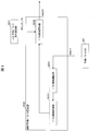
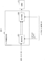
- H04—ELECTRIC COMMUNICATION TECHNIQUE
- H04N—PICTORIAL COMMUNICATION, e.g. TELEVISION
- H04N19/00—Methods or arrangements for coding, decoding, compressing or decompressing digital video signals
- H04N19/44—Decoders specially adapted therefor, e.g. video decoders which are asymmetric with respect to the encoder
- H04N19/45—Decoders specially adapted therefor, e.g. video decoders which are asymmetric with respect to the encoder performing compensation of the inverse transform mismatch, e.g. Inverse Discrete Cosine Transform [IDCT] mismatch
-
- H—ELECTRICITY
- H04—ELECTRIC COMMUNICATION TECHNIQUE
- H04N—PICTORIAL COMMUNICATION, e.g. TELEVISION
- H04N19/00—Methods or arrangements for coding, decoding, compressing or decompressing digital video signals
- H04N19/50—Methods or arrangements for coding, decoding, compressing or decompressing digital video signals using predictive coding
- H04N19/503—Methods or arrangements for coding, decoding, compressing or decompressing digital video signals using predictive coding involving temporal prediction
- H04N19/51—Motion estimation or motion compensation
- H04N19/513—Processing of motion vectors
-
- H—ELECTRICITY
- H04—ELECTRIC COMMUNICATION TECHNIQUE
- H04N—PICTORIAL COMMUNICATION, e.g. TELEVISION
- H04N19/00—Methods or arrangements for coding, decoding, compressing or decompressing digital video signals
- H04N19/50—Methods or arrangements for coding, decoding, compressing or decompressing digital video signals using predictive coding
- H04N19/503—Methods or arrangements for coding, decoding, compressing or decompressing digital video signals using predictive coding involving temporal prediction
- H04N19/51—Motion estimation or motion compensation
- H04N19/513—Processing of motion vectors
- H04N19/517—Processing of motion vectors by encoding
- H04N19/52—Processing of motion vectors by encoding by predictive encoding
-
- H—ELECTRICITY
- H04—ELECTRIC COMMUNICATION TECHNIQUE
- H04N—PICTORIAL COMMUNICATION, e.g. TELEVISION
- H04N19/00—Methods or arrangements for coding, decoding, compressing or decompressing digital video signals
- H04N19/50—Methods or arrangements for coding, decoding, compressing or decompressing digital video signals using predictive coding
- H04N19/503—Methods or arrangements for coding, decoding, compressing or decompressing digital video signals using predictive coding involving temporal prediction
- H04N19/51—Motion estimation or motion compensation
- H04N19/523—Motion estimation or motion compensation with sub-pixel accuracy
-
- H—ELECTRICITY
- H04—ELECTRIC COMMUNICATION TECHNIQUE
- H04N—PICTORIAL COMMUNICATION, e.g. TELEVISION
- H04N19/00—Methods or arrangements for coding, decoding, compressing or decompressing digital video signals
- H04N19/50—Methods or arrangements for coding, decoding, compressing or decompressing digital video signals using predictive coding
- H04N19/59—Methods or arrangements for coding, decoding, compressing or decompressing digital video signals using predictive coding involving spatial sub-sampling or interpolation, e.g. alteration of picture size or resolution
Definitions
- the present invention relates to a predicted image generation device, a moving image decoding device, and a moving image encoding device.
- a moving image encoding device that generates encoded data by encoding the moving image, and a moving image that generates a decoded image by decoding the encoded data
- An image decoding device is used.
- the moving image encoding method include a method proposed in H.264 / MPEG-4.AVC and HEVC (High-Efficiency Video Coding).
- an image (picture) constituting a moving image is a slice obtained by dividing the image, a coding unit obtained by dividing the slice (coding unit (Coding Unit )), And a hierarchical structure composed of prediction units (PU) and transform units (TU), which are blocks obtained by dividing the coding unit, and is encoded / decoded for each block.
- PU prediction units
- TU transform units
- a predicted image is usually generated based on a local decoded image obtained by encoding / decoding an input image, and the predicted image is generated from the input image (original image).
- a prediction residual obtained by subtraction (sometimes referred to as “difference image” or “residual image”) is encoded. Examples of the method for generating a predicted image include inter-screen prediction (inter prediction) and intra-screen prediction (intra prediction).
- Non-Patent Document 1 can be cited as a technique for encoding and decoding moving images in recent years.
- a motion compensation filter is used in motion compensation processing when generating a predicted image.
- the required filter coefficient increases, and a first problem has arisen that the amount of memory required to store the filter coefficient increases.
- the present invention is to provide an image decoding device, an image encoding device, and a predicted image generation device capable of solving at least one of the first and second problems.
- a predicted image generation apparatus is a predicted image generation apparatus that generates a predicted image by performing motion compensation on a reference image.
- a filter unit that operates on a motion vector applied image with 1 / Mac pixel accuracy obtained by applying a motion vector, and the filter unit has a phase i (i is an integer of 0 to Mac-1) and Filter processing using the filter coefficient mcFilter [i] [k] specified by the filter coefficient position k (k is an integer of 0 to Ntaps-1 and Ntaps is the number of taps) is applied to the motion vector applied image.
- the filter coefficient mcFilter [i] [k] is weighted with the filter coefficient mcFilter [p] [k] (P ⁇ i) and the filter coefficient mcFilter [q] [k] (Q ⁇ i). There is an average relationship.
- a predicted image generation apparatus is a predicted image generation apparatus that generates a predicted image for each predicted block by performing motion compensation on a reference image.
- a motion vector deriving unit for deriving a motion vector by adding or subtracting a difference vector to or from a prediction vector for each prediction block, the motion vector deriving unit corresponding to the size of the prediction block Switch the accuracy of the motion vector derived for.
- a predicted image generation apparatus is a predicted image generation apparatus that generates a predicted image for each predicted block by performing motion compensation on a reference image.
- a motion vector deriving unit for deriving a motion vector by adding or subtracting a difference vector to or from a prediction vector for each prediction block, the motion vector deriving unit corresponding to the size of a quantization parameter related to the prediction block thus, the accuracy of the motion vector derived for the prediction block is switched.
- a predicted image generation apparatus is a predicted image generation apparatus that generates a predicted image by performing motion compensation on a reference image, and performs inverse quantization.
- a predicted image generation apparatus is a predicted image generation apparatus that generates a predicted image by performing motion compensation on a reference image.
- a motion vector deriving unit for deriving a motion vector by adding or subtracting a difference vector to the motion vector, and the motion vector deriving unit performs quantization when a flag indicating the accuracy of the motion vector indicates a first value
- the accuracy of the inverse quantization process for the difference vector is switched according to the quantized value of the difference vector, and the flag indicating the accuracy of the motion vector indicates the second value
- the quantization of the quantized difference vector Regardless of the quantization value, the inverse quantization process is performed on the difference vector with a certain accuracy.
- a predicted image generation apparatus is a predicted image generation apparatus that generates a predicted image by performing motion compensation on a reference image.
- FIG. 1 It is a figure which shows the hierarchical structure of the data of the encoding stream which concerns on this embodiment. It is a figure which shows the pattern of PU division
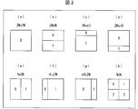
- (A) to (h) are PU partition modes of 2N ⁇ 2N, 2N ⁇ N, 2N ⁇ nU, 2N ⁇ nD, N ⁇ 2N, nL ⁇ 2N, nR ⁇ 2N, and N ⁇ N, respectively.
- the partition shape in case is shown.
- FIG. 1 is a schematic diagram illustrating a configuration of an image transmission system according to an embodiment of the present invention. It is a flowchart which shows the flow of the inter prediction syntax decoding process performed by the inter prediction parameter decoding control part which concerns on this embodiment. It is a flowchart which shows the example of the difference vector decoding process which concerns on this embodiment. It is a flowchart which shows the other example of the difference vector decoding process which concerns on this embodiment. It is a flowchart which shows the flow of the motion vector derivation process performed by the inter prediction parameter decoding part which concerns on this embodiment. It is a flowchart which shows the example of the difference vector derivation process which concerns on this embodiment. It is a flowchart which shows the example of the prediction vector round process which concerns on this embodiment.
- FIG. 5 is a flowchart specifically illustrating an example of motion vector scale derivation processing according to the present embodiment. It is a flowchart which shows more specifically the other example of the motion vector scale derivation processing concerning this embodiment. It is a flowchart which shows more specifically the other example of the motion vector scale derivation processing concerning this embodiment.
- (A) to (c) are tables showing the relationship between the basic vector accuracy according to the present embodiment and a parameter (shiftS) indicating motion vector accuracy set (switched) by the block size of the target block.
- (A) to (c) are tables showing the relationship between the block size of the target block and the parameter (shiftS) indicating the motion vector accuracy set (switched) by the motion vector accuracy flag according to the present embodiment. .
- (A) to (c) are tables showing parameters (shiftS) indicating motion vector accuracy set (switched) by QP according to the present embodiment.
- (A) And (b) is a table which shows the motion vector precision (shiftS) set (switched) by QP and the motion vector precision flag which concern on this embodiment. It is a graph which shows the relationship between the quantized difference vector and dequantized difference vector which concern on this embodiment. It is a flowchart which shows more specifically the other example of the motion vector scale derivation processing concerning this embodiment.
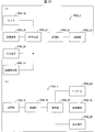
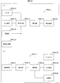
- It is a block diagram which shows the specific structure of the motion compensation part which concerns on this embodiment. It is a figure which shows an example of the filter coefficient which concerns on this embodiment.
- (A) is a figure which shows the example which the motion compensation filter part which concerns on this embodiment calculates the filter coefficient of an odd phase from the filter coefficient of an even phase.
- (B) is a figure which shows the example in which the motion compensation filter part which concerns on this embodiment calculates the filter coefficient of an even-numbered phase from the filter coefficient of an odd-numbered phase. It is the figure shown about the structure of the transmitter which mounts the said image coding apparatus, and the receiver which mounts the said image decoding apparatus.
- (A) shows a transmission device equipped with an image encoding device, and (b) shows a reception device equipped with an image decoding device. It is the figure which showed about the structure of the recording device carrying the said image coding apparatus, and the reproducing
- (A) shows a recording device equipped with an image encoding device, and (b) shows a playback device equipped with an image decoding device.
- FIG. 14 is a schematic diagram showing the configuration of the image transmission system 1 according to the present embodiment.
- the image transmission system 1 is a system that transmits a code obtained by encoding an image to be encoded and displays an image obtained by decoding the transmitted code.
- the image transmission system 1 includes an image encoding device (moving image encoding device) 11, a network 21, an image decoding device (moving image decoding device) 31, and an image display device 41.
- a signal T indicating a single layer image or a plurality of layers of images is input to the image encoding device 11.
- a layer is a concept used to distinguish a plurality of pictures when there are one or more pictures constituting a certain time. For example, when the same picture is encoded with a plurality of layers having different image quality and resolution, scalable encoding is performed, and when a picture of a different viewpoint is encoded with a plurality of layers, view scalable encoding is performed.
- inter-layer prediction, inter-view prediction When prediction is performed between pictures of a plurality of layers (inter-layer prediction, inter-view prediction), encoding efficiency is greatly improved. Further, even when prediction is not performed (simultaneous casting), encoded data can be collected.
- the network 21 transmits the encoded stream Te generated by the image encoding device 11 to the image decoding device 31.
- the network 21 is the Internet, a wide area network (WAN: Wide Area Network), a small network (LAN: Local Area Network), or a combination thereof.
- the network 21 is not necessarily limited to a bidirectional communication network, and may be a one-way or bidirectional communication network that transmits broadcast waves such as terrestrial digital broadcasting and satellite broadcasting.
- the network 21 may be replaced with a storage medium that records an encoded stream Te such as a DVD (Digital Versatile Disc) or a BD (Blue-ray Disc: registered trademark).
- the image decoding device 31 decodes each of the encoded streams Te transmitted by the network 21, and generates one or a plurality of decoded layer images Td (decoded viewpoint images Td) respectively decoded.
- the image display device 41 displays all or part of one or a plurality of decoded layer images Td generated by the image decoding device 31. For example, in view scalable coding, a 3D image (stereoscopic image) and a free viewpoint image are displayed in all cases, and a 2D image is displayed in some cases.
- the image display device 41 includes, for example, a display device such as a liquid crystal display or an organic EL (Electro-luminescence) display.
- a display device such as a liquid crystal display or an organic EL (Electro-luminescence) display.
- an enhancement layer image with high image quality is displayed.
- a base layer image that does not require higher processing capability and display capability is displayed as the enhancement layer.
- FIG. 1 is a diagram showing a hierarchical structure of data in the encoded stream Te.
- the encoded stream Te illustratively includes a sequence and a plurality of pictures constituting the sequence.
- (A) to (f) of FIG. 1 respectively show a sequence layer that defines a sequence SEQ, a picture layer that defines a picture PICT, a slice layer that defines a slice S, a slice data layer that defines slice data, and a slice data.
- CU encoding unit
- Sequence layer In the sequence layer, a set of data referred to by the image decoding device 31 in order to decode a sequence SEQ to be processed (hereinafter also referred to as a target sequence) is defined.
- the sequence SEQ includes a video parameter set (Sequence Parameter Set), a picture parameter set PPS (Picture Parameter Set), a picture PICT, and an additional extension as shown in FIG.
- Information SEI Supplemental Enhancement Information
- # indicates the layer ID.
- FIG. 1 shows an example in which encoded data of # 0 and # 1, that is, layer 0 and layer 1, exists, the type of layer and the number of layers are not dependent on this.
- the video parameter set VPS is a set of encoding parameters common to a plurality of moving images, a plurality of layers included in the moving image, and encoding parameters related to individual layers in a moving image composed of a plurality of layers.
- a set is defined.
- the sequence parameter set SPS defines a set of encoding parameters that the image decoding device 31 refers to in order to decode the target sequence. For example, the width and height of the picture are defined. A plurality of SPSs may exist. In that case, one of a plurality of SPSs is selected from the PPS.
- a set of encoding parameters referred to by the image decoding device 31 in order to decode each picture in the target sequence is defined.
- a quantization width reference value (pic_init_qp_minus26) used for picture decoding and a flag (weighted_pred_flag) indicating application of weighted prediction are included.
- Picture layer In the picture layer, a set of data referred to by the image decoding device 31 for decoding a picture PICT to be processed (hereinafter also referred to as a target picture) is defined.
- the picture PICT includes slices S0 to SNS-1 as shown in FIG. 1B (NS is the total number of slices included in the picture PICT).
- slice layer In the slice layer, a set of data referred to by the image decoding device 31 for decoding the slice S to be processed (also referred to as a target slice) is defined. As shown in FIG. 1C, the slice S includes a slice header SH and slice data SDATA.
- the slice header SH includes an encoding parameter group that is referred to by the image decoding device 31 in order to determine a decoding method of the target slice.
- Slice type designation information (slice_type) for designating a slice type is an example of an encoding parameter included in the slice header SH.
- I slice using only intra prediction at the time of encoding (2) P slice using unidirectional prediction or intra prediction at the time of encoding, (3) B-slice using unidirectional prediction, bidirectional prediction, or intra prediction at the time of encoding may be used.
- the slice header SH may include a reference (pic_parameter_set_id) to the picture parameter set PPS included in the sequence layer.
- the slice data layer a set of data referred to by the image decoding device 31 for decoding the slice data SDATA to be processed is defined.
- the slice data SDATA includes a coded tree block (CTB) as shown in FIG.
- the CTB is a fixed-size block (for example, 64 ⁇ 64) constituting a slice, and may be called a maximum coding unit (LCU) and a coding tree unit (CTU).
- LCU maximum coding unit
- CTU coding tree unit
- the coding tree layer defines a set of data that the image decoding device 31 refers to in order to decode a coding tree block to be processed.
- the coding tree block is divided by recursive quadtree division.
- a tree-structured node obtained by recursive quadtree partitioning is called a coding tree.
- An intermediate node of the quadtree is a coded quadtree (CQT), and the coded tree block itself is also defined as the highest CQT.
- the CQT includes a split flag (split_flag). When the split_flag is 1, the CQT is split into four coding tree units CQT.
- the coding tree unit CQT is not divided and has one coding unit (CU: Coded Unit) as a node.
- the coding unit CU is a terminal node of the coding tree layer and is not further divided in this layer.
- the encoding unit CU is a basic unit of the encoding process.
- the size of the encoding unit is any of 64 ⁇ 64 pixels, 32 ⁇ 32 pixels, 16 ⁇ 16 pixels, and 8 ⁇ 8 pixels. It can take.
- the encoding unit layer defines a set of data referred to by the image decoding device 31 in order to decode the processing target encoding unit.
- the encoding unit includes an encoding tree, a prediction tree, a conversion tree, and a CU header CUF.
- a division flag, a division pattern, a prediction mode, and the like are defined.
- the prediction tree defines prediction information (reference picture index, motion vector, etc.) of each prediction block obtained by dividing the coding unit into one or a plurality.
- the prediction block is one or a plurality of non-overlapping areas constituting the coding unit.
- the prediction tree includes one or a plurality of prediction blocks obtained by the above division.
- a prediction unit obtained by further dividing the prediction block is referred to as a “sub-block”.
- a sub-block (prediction block) is composed of one or a plurality of pixels. When the sizes of the prediction block and the sub block are equal, the number of sub blocks in the prediction block is one. If the prediction block is larger than the size of the sub-block, the prediction block is divided into sub-blocks. For example, when the prediction block is 8 ⁇ 8 and the sub-block is 4 ⁇ 4, the prediction block is horizontally divided into two and vertically divided into two, and is divided into four sub-blocks.
- Prediction processing is performed for each prediction block (sub-block).
- a prediction block which is a unit of prediction is also referred to as a prediction unit (PU, prediction unit).
- Intra prediction is prediction within the same picture
- inter prediction refers to prediction processing performed between different pictures (for example, between display times and between layer images).
- the division method is encoded by the PU division mode (part_mode) of the encoded data.
- the division includes 2N ⁇ 2N (the same size as the encoding unit), 2N ⁇ N, 2N ⁇ nU, 2N ⁇ nD, N ⁇ 2N, nL ⁇ 2N, nR ⁇ 2N, and N ⁇ N.
- 2N ⁇ nU indicates that a 2N ⁇ 2N encoding unit is divided into two regions of 2N ⁇ 0.5N and 2N ⁇ 1.5N in order from the top.
- 2N ⁇ nD indicates that a 2N ⁇ 2N encoding unit is divided into two regions of 2N ⁇ 1.5N and 2N ⁇ 0.5N in order from the top.
- nL ⁇ 2N indicates that a 2N ⁇ 2N encoding unit is divided into two regions of 0.5N ⁇ 2N and 1.5N ⁇ 2N in order from the left.
- nR ⁇ 2N indicates that a 2N ⁇ 2N encoding unit is divided into two regions of 1.5N ⁇ 2N and 0.5N ⁇ 1.5N in order from the left. Since the number of divisions is one of 1, 2, and 4, the number of PUs included in the CU is 1 to 4. These PUs are expressed in order as PU0, PU1, PU2, and PU3.
- FIG. 2 specifically show the positions of the PU partition boundaries in the CU for each partition type.
- FIG. 2A shows a 2N ⁇ 2N PU partitioning mode in which CU partitioning is not performed.
- 2B, 2C, and 2D show the partition shapes when the PU partition modes are 2N ⁇ N, 2N ⁇ nU, and 2N ⁇ nD, respectively. ing.
- partitions when the PU partition mode is 2N ⁇ N, 2N ⁇ nU, and 2N ⁇ nD are collectively referred to as a horizontally long partition.
- FIG. 2 show the shapes of partitions when the PU partition modes are N ⁇ 2N, nL ⁇ 2N, and nR ⁇ 2N, respectively.
- partitions when the PU partition type is N ⁇ 2N, nL ⁇ 2N, and nR ⁇ 2N are collectively referred to as a vertically long partition.
- the horizontally long partition and the vertically long partition are collectively referred to as a rectangular partition.
- FIG. 2 shows the shape of the partition when the PU partition mode is N ⁇ N.
- the PU partitioning modes shown in FIGS. 2A and 2H are also referred to as square partitioning based on the shape of the partition.
- the PU division modes in FIGS. 2B to 2G are also referred to as non-square divisions.
- the numbers given to the respective regions indicate the identification numbers of the regions, and the processing is performed on the regions in the order of the identification numbers. That is, the identification number represents the scan order of the partitions.
- FIGS. 2A to 2H the upper left is the CU reference point (origin).
- the encoding unit is divided into one or a plurality of transform blocks, and the position and size of each transform block are defined.
- the transform block is one or a plurality of non-overlapping areas constituting the encoding unit.
- the conversion tree includes one or a plurality of conversion blocks obtained by the above division.
- the division in the transformation tree includes the one in which an area having the same size as that of the encoding unit is assigned as the transformation block, and the one in the recursive quadtree division like the above-described division in the tree block.
- a transform block that is a unit of transformation is also referred to as a transform unit (TU).
- the prediction image of the prediction unit is derived by a prediction parameter associated with the prediction unit.
- the prediction parameters include a prediction parameter for intra prediction or a prediction parameter for inter prediction.
- prediction parameters for inter prediction inter prediction (inter prediction parameters) will be described.
- the inter prediction parameter includes prediction list use flags predFlagL0 and predFlagL1, reference picture indexes refIdxL0 and refIdxL1, and vectors mvL0 and mvL1.
- the prediction list use flags predFlagL0 and predFlagL1 are flags indicating whether or not reference picture lists called L0 list and L1 list are used, respectively, and a reference picture list corresponding to a value of 1 is used.
- the prediction list use flag information can also be expressed by an inter prediction flag inter_pred_idc described later.
- a prediction list use flag is used in a prediction image generation unit (prediction image generation device) 308 and a prediction parameter memory 307 described later.
- an inter prediction flag inter_pred_idc is used when decoding information about which reference picture list is used from encoded data.
- Syntax elements for deriving inter prediction parameters included in the encoded data include, for example, a partition mode part_mode, a merge flag merge_flag, a merge index merge_idx, an inter prediction flag inter_pred_idc, a reference picture index refIdxLX, a prediction vector index mvp_LX_idx, and a difference There is a vector mvdLX.
- FIG. 3 is a conceptual diagram illustrating an example of a reference picture list.
- the reference picture list 601 five rectangles arranged in a line on the left and right indicate reference pictures, respectively.
- the codes P1, P2, Q0, P3, and P4 shown in order from the left end to the right are codes indicating respective reference pictures.
- P such as P1 indicates the viewpoint P
- Q of Q0 indicates a viewpoint Q different from the viewpoint P.
- the subscripts P and Q indicate the picture order number POC.
- a downward arrow directly below refIdxLX indicates that the reference picture index refIdxLX is an index that refers to the reference picture Q0 in the reference picture memory 306.
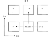
- FIG. 4 is a conceptual diagram illustrating an example of a reference picture.
- the horizontal axis indicates the display time
- the vertical axis indicates the viewpoint.
- the rectangles shown in FIG. 4 with 2 rows and 3 columns (6 in total) indicate pictures.
- the rectangle in the second column from the left in the lower row indicates a picture to be decoded (target picture), and the remaining five rectangles indicate reference pictures.
- a reference picture Q0 indicated by an upward arrow from the target picture is a picture that has the same display time as the target picture and a different viewpoint. In the displacement prediction based on the target picture, the reference picture Q0 is used.
- a reference picture P1 indicated by a left-pointing arrow from the target picture is a past picture at the same viewpoint as the target picture.
- a reference picture P2 indicated by a right-pointing arrow from the target picture is a future picture at the same viewpoint as the target picture. In motion prediction based on the target picture, the reference picture P1 or P2 is used.
- Inter prediction flag and prediction list usage flag The relationship between the inter prediction flag and the prediction list use flags predFlagL0 and predFlagL1 can be mutually converted as follows. Therefore, as an inter prediction parameter, a prediction list use flag may be used, or an inter prediction flag may be used. Hereinafter, the determination using the prediction list use flag may be replaced with the inter prediction flag. Conversely, the determination using the inter prediction flag may be replaced with a prediction list use flag.
- >> is a right shift
- ⁇ is a left shift.
- the prediction parameter decoding (encoding) method includes a merge prediction (merge) mode and an AMVP (Adaptive Motion Vector Prediction) mode.
- the merge flag merge_flag is a flag for identifying these.
- the prediction parameter of the target PU is derived using the prediction parameter of the already processed block.
- the merge prediction mode is a mode in which the prediction parameters of the neighboring PUs already derived are used as they are without including the prediction list use flag predFlagLX (or the inter prediction flag inter_pred_idc), the reference picture index refIdxLX, and the motion vector mvLX in the encoded data.
- the AMVP mode is a mode in which the inter prediction flag inter_pred_idc, the reference picture index refIdxLX, and the motion vector mvLX are included in the encoded data.
- the motion vector mvLX is encoded as a prediction vector index mvp_LX_idx for identifying the prediction vector mvpLX and a difference vector mvdLX.
- the inter prediction flag inter_pred_idc is data indicating the type and number of reference pictures, and takes any value of Pred_L0, Pred_L1, and Pred_Bi.
- Pred_L0 and Pred_L1 indicate that reference pictures stored in reference picture lists called an L0 list and an L1 list are used, respectively, and that both use one reference picture (single prediction). Prediction using the L0 list and the L1 list are referred to as L0 prediction and L1 prediction, respectively.
- Pred_Bi indicates that two reference pictures are used (bi-prediction), and indicates that two reference pictures stored in the L0 list and the L1 list are used.
- the prediction vector index mvp_LX_idx is an index indicating a prediction vector
- the reference picture index refIdxLX is an index indicating a reference picture stored in the reference picture list.
- LX is a description method used when L0 prediction and L1 prediction are not distinguished.
- refIdxL0 is a reference picture index used for L0 prediction
- refIdxL1 is a reference picture index used for L1 prediction
- refIdx (refIdxLX) is a notation used when refIdxL0 and refIdxL1 are not distinguished.
- the merge index merge_idx is an index indicating which one of the prediction parameter candidates (merge candidates) derived from the processed block is used as the prediction parameter of the decoding target block.
- target block may be a prediction block that is one level higher than a plurality of prediction blocks, or may be an encoding unit including the plurality of prediction blocks.
- the motion vector mvLX includes a displacement vector (disparity vector, indicating a shift amount between two blocks at the same time as a motion vector in a narrow sense (motion vector in a narrow sense) indicating a shift amount between blocks on two pictures at different times. (Parallax vector).
- the motion vector and the displacement vector are not distinguished, and are simply referred to as a motion vector mvLX.
- a prediction vector and a difference vector related to the motion vector mvLX are referred to as a prediction vector mvpLX and a difference vector mvdLX, respectively. Whether the motion vector mvLX and the difference vector mvdLX are motion vectors or displacement vectors is identified using a reference picture index refIdxLX attached to the vectors.
- FIG. 5 is a schematic diagram illustrating a configuration of the image decoding device 31 according to the present embodiment.
- the image decoding device 31 includes an entropy decoding unit 301, a prediction parameter decoding unit (prediction image generation device) 302, a reference picture memory (reference image storage unit, frame memory) 306, and a prediction parameter memory (prediction parameter storage unit, frame memory) 307.
- the prediction parameter decoding unit 302 includes an inter prediction parameter decoding unit (motion vector derivation unit) 303 and an intra prediction parameter decoding unit 304.
- the predicted image generation unit 308 includes an inter predicted image generation unit 309 and an intra predicted image generation unit 310.
- the entropy decoding unit 301 performs entropy decoding on the encoded stream Te input from the outside, and separates and decodes individual codes (syntax elements).
- the separated codes include prediction information for generating a prediction image and residual information for generating a difference image.
- the entropy decoding unit 301 outputs a part of the separated code to the prediction parameter decoding unit 302.
- Some of the separated codes are, for example, a prediction mode PredMode, a partition mode part_mode, a merge flag merge_flag, a merge index merge_idx, an inter prediction flag inter_pred_idc, a reference picture index refIdxLX, a prediction vector index mvp_LX_idx, and a difference vector mvdLX.
- Control of which code to decode is performed based on an instruction from the prediction parameter decoding unit 302.
- the entropy decoding unit 301 outputs the quantization coefficient to the inverse quantization / inverse DCT unit 311.
- the quantization coefficient is a coefficient obtained by performing quantization by performing DCT (Discrete Cosine Transform) on the residual signal in the encoding process.
- the inter prediction parameter decoding unit 303 decodes the inter prediction parameter with reference to the prediction parameter stored in the prediction parameter memory 307 based on the code input from the entropy decoding unit 301.
- the inter prediction parameter decoding unit 303 outputs the decoded inter prediction parameter to the prediction image generation unit 308 and stores it in the prediction parameter memory 307. Details of the inter prediction parameter decoding unit 303 will be described later.
- the intra prediction parameter decoding unit 304 refers to the prediction parameter stored in the prediction parameter memory 307 on the basis of the code input from the entropy decoding unit 301 and decodes the intra prediction parameter.
- the intra prediction parameter is a parameter used in a process of predicting a picture block within one picture, for example, an intra prediction mode IntraPredMode.
- the intra prediction parameter decoding unit 304 outputs the decoded intra prediction parameter to the prediction image generation unit 308 and stores it in the prediction parameter memory 307.
- the intra prediction parameter decoding unit 304 may derive different intra prediction modes depending on luminance and color difference.
- the intra prediction parameter decoding unit 304 decodes the luminance prediction mode IntraPredModeY as the luminance prediction parameter and the color difference prediction mode IntraPredModeC as the color difference prediction parameter.
- the luminance prediction mode IntraPredModeY is a 35 mode, and corresponds to planar prediction (0), DC prediction (1), and direction prediction (2 to 34).
- the color difference prediction mode IntraPredModeC uses one of the planar prediction (0), the DC prediction (1), the direction prediction (2 to 34), and the LM mode (35).
- the intra prediction parameter decoding unit 304 decodes a flag indicating whether IntraPredModeC is the same mode as the luminance mode, and assigns IntraPredModeY to IntraPredModeC if it indicates that the flag is the same mode as the luminance mode. If the flag indicates that the mode is different from the luminance mode, the intra prediction parameter decoding unit 304 uses IntraPredModeC as planar prediction (0), DC prediction (1), direction prediction (2 to 34), and LM mode (35 ) May be decrypted.
- the reference picture memory 306 stores the reference picture block (reference picture block) generated by the adding unit 312 at a predetermined position for each picture and block to be decoded.
- the prediction parameter memory 307 stores the prediction parameter in a predetermined position for each decoding target picture and block. Specifically, the prediction parameter memory 307 stores the inter prediction parameter decoded by the inter prediction parameter decoding unit 303, the intra prediction parameter decoded by the intra prediction parameter decoding unit 304, and the prediction mode predMode separated by the entropy decoding unit 301. .
- the stored inter prediction parameters include, for example, a prediction list use flag predFlagLX (inter prediction flag inter_pred_idc), a reference picture index refIdxLX, and a motion vector mvLX.
- the prediction image generation unit 308 receives the prediction mode predMode input from the entropy decoding unit 301 and the prediction parameter from the prediction parameter decoding unit 302. Further, the predicted image generation unit 308 reads a reference picture from the reference picture memory 306. The predicted image generation unit 308 generates a predicted picture block P (predicted image) using the input prediction parameter and the read reference picture in the prediction mode indicated by the prediction mode predMode.
- the inter prediction image generation unit 309 uses the inter prediction parameter input from the inter prediction parameter decoding unit 303 and the read reference picture to perform a prediction picture block by inter prediction. P is generated.
- the prediction picture block P corresponds to the prediction unit PU.
- the PU corresponds to a part of a picture composed of a plurality of pixels as a unit for performing the prediction process as described above, that is, a decoding target block on which the prediction process is performed at a time.
- the inter predicted image generation unit 309 uses the decoding target block as a reference from the reference picture indicated by the reference picture index refIdxLX.
- the reference picture block at the position indicated by mvLX is read from the reference picture memory 306.
- the inter prediction image generation unit 309 performs prediction on the read reference picture block to generate a prediction picture block P.
- the inter prediction image generation unit 309 outputs the generated prediction picture block P to the addition unit 312.
- the intra predicted image generation unit 310 When the prediction mode predMode indicates the intra prediction mode, the intra predicted image generation unit 310 performs intra prediction using the intra prediction parameter input from the intra prediction parameter decoding unit 304 and the read reference picture. Specifically, the intra predicted image generation unit 310 reads, from the reference picture memory 306, a reference picture block that is a decoding target picture and is in a predetermined range from the decoding target block among blocks that have already been decoded.
- the predetermined range is, for example, any of the left, upper left, upper, and upper right adjacent blocks when the decoding target block sequentially moves in a so-called raster scan order, and varies depending on the intra prediction mode.
- the raster scan order is an order in which each row is sequentially moved from the left end to the right end in each picture from the upper end to the lower end.
- the intra-predicted image generation unit 310 generates a predicted picture block by performing prediction in the prediction mode indicated by the intra-prediction mode IntraPredMode for the read reference picture block.
- the intra predicted image generation unit 310 outputs the generated predicted picture block P to the addition unit 312.
- the intra prediction image generation unit 310 When the intra prediction parameter decoding unit 304 derives different intra prediction modes for luminance and color difference, the intra prediction image generation unit 310 performs planar prediction (0), DC prediction (1), and so on according to the luminance prediction mode IntraPredModeY. A luminance prediction picture block is generated by any of the direction predictions (2 to 34). Further, the intra predicted image generation unit 310 predicts the color difference by any one of the planar prediction (0), the DC prediction (1), the direction prediction (2 to 344), and the LM mode (35) according to the color difference prediction mode IntraPredModeC. Generate a picture block.
- the inverse quantization / inverse DCT unit 311 inversely quantizes the quantization coefficient input from the entropy decoding unit 301 to obtain a DCT coefficient.
- the inverse quantization / inverse DCT unit 311 performs inverse DCT (Inverse Discrete Cosine Transform) on the obtained DCT coefficient to calculate a decoded residual signal.
- the inverse quantization / inverse DCT unit 311 outputs the calculated decoded residual signal to the addition unit 312 and the residual storage unit 313.
- the adder 312 outputs, for each pixel, the prediction picture block P input from the inter predicted image generator 309 and the intra predicted image generator 310 and the signal value of the decoded residual signal input from the inverse quantization / inverse DCT unit 311. Addition to generate a reference picture block.
- the adder 312 stores the generated reference picture block in the reference picture memory 306, and outputs a decoded layer image Td in which the generated reference picture block is integrated for each picture to the outside.
- FIG. 6 is a schematic diagram illustrating a configuration of the inter prediction parameter decoding unit 303 according to the present embodiment.
- the inter prediction parameter decoding unit 303 includes an inter prediction parameter decoding control unit (motion vector deriving unit) 3031, an AMVP prediction parameter deriving unit 3032, an adding unit 3035, and a merge prediction parameter deriving unit 3036.
- the inter prediction parameter decoding control unit 3031 instructs the entropy decoding unit 301 to decode a code (syntax element) related to inter prediction, and a code (syntax element) included in the encoded data, for example, a division mode part_mode, Merge flag merge_flag, merge index merge_idx, inter prediction flag inter_pred_idc, reference picture index refIdxLX, prediction vector index mvp_LX_idx, and difference vector mvdLX are extracted.
- the inter prediction parameter decoding control unit 3031 first extracts a merge flag.
- the inter prediction parameter decoding control unit 3031 expresses that a certain syntax element is to be extracted, it means that the entropy decoding unit 301 is instructed to decode a certain syntax element, and the corresponding syntax element is read from the encoded data. To do.
- the inter prediction parameter decoding control unit 3031 extracts the merge index merge_idx as a prediction parameter related to merge prediction.
- the inter prediction parameter decoding control unit 3031 outputs the extracted merge index merge_idx to the merge prediction parameter derivation unit 3036.
- the inter prediction parameter decoding control unit 3031 uses the entropy decoding unit 301 to extract the AMVP prediction parameter from the encoded data.
- AMVP prediction parameters include an inter prediction flag inter_pred_idc, a reference picture index refIdxLX, a prediction vector index mvp_LX_idx, and a difference vector mvdLX.
- the inter prediction parameter decoding control unit 3031 outputs the prediction list use flag predFlagLX derived from the extracted inter prediction flag inter_pred_idc and the reference picture index refIdxLX to the AMVP prediction parameter derivation unit 3032 and the prediction image generation unit 308 (FIG. 5).
- the inter prediction parameter decoding control unit 3031 outputs the extracted prediction vector index mvp_LX_idx to the AMVP prediction parameter derivation unit 3032.
- the inter prediction parameter decoding control unit 3031 outputs the extracted difference vector mvdLX to the addition unit 3035.
- FIG. 7 is a schematic diagram illustrating the configuration of the merge prediction parameter deriving unit 3036 according to the present embodiment.
- the merge prediction parameter derivation unit 3036 includes a merge candidate derivation unit 30361 (prediction vector calculation unit) and a merge candidate selection unit 30362.
- the merge candidate storage unit 303611 stores the merge candidates input from the merge candidate derivation unit 30361.
- the merge candidate includes a prediction list use flag predFlagLX, a motion vector mvLX, and a reference picture index refIdxLX.
- an index is assigned to the stored merge candidates according to a predetermined rule.
- the merge candidate derivation unit 30361 derives a merge candidate using the motion vector of the adjacent block that has already been decoded and the reference picture index refIdxLX as they are.
- merge candidates may be derived using affine prediction. This method is described in detail below.
- the merge candidate derivation unit 30361 may use affine prediction for a spatial merge candidate derivation process, a temporal merge (inter-frame merge) candidate derivation process, a merge merge candidate derivation process, and a zero merge candidate derivation process described later.
- Affine prediction is performed in units of sub-blocks, and prediction parameters are stored in the prediction parameter memory 307 for each sub-block.
- the affine prediction may be performed on a pixel basis.
- the merge candidate derivation unit 30361 reads and reads the prediction parameters (prediction list use flag predFlagLX, motion vector mvLX, reference picture index refIdxLX) stored in the prediction parameter memory 307 according to a predetermined rule.
- the predicted parameters are derived as merge candidates.
- the prediction parameter to be read is a prediction parameter related to each of the blocks within a predetermined range from the decoding target block (for example, all or a part of the blocks in contact with the lower left end, the upper left upper end, and the upper right end of the decoding target block). is there.
- the merge candidates derived by the merge candidate deriving unit 30361 are stored in the merge candidate storage unit 303611.
- the merge candidate derivation unit 30361 reads the prediction parameter of the block in the reference image including the lower right coordinate of the decoding target block from the prediction parameter memory 307 and sets it as a merge candidate.
- the reference picture designation method may be, for example, the reference picture index refIdxLX designated in the slice header, or may be designated using the smallest reference picture index refIdxLX of the block adjacent to the decoding target block.
- the merge candidates derived by the merge candidate deriving unit 30361 are stored in the merge candidate storage unit 303611.
- the merge candidate derivation unit 30361 combines two different derived merge candidate vectors and reference picture indexes that have already been derived and stored in the merge candidate storage unit 303611 as L0 and L1 vectors, respectively. Thus, a merge merge candidate is derived.
- the merge candidates derived by the merge candidate deriving unit 30361 are stored in the merge candidate storage unit 303611.
- the merge candidate derivation unit 30361 derives a merge candidate in which the reference picture index refIdxLX is 0 and both the X component and the Y component of the motion vector mvLX are 0.
- the merge candidates derived by the merge candidate deriving unit 30361 are stored in the merge candidate storage unit 303611.
- the merge candidate selection unit 30362 selects a merge candidate assigned with an index corresponding to the merge index merge_idx input from the inter prediction parameter decoding control unit 3031 among the merge candidates stored in the merge candidate storage unit 303611. As an inter prediction parameter.
- the merge candidate selection unit 30362 stores the selected merge candidate in the prediction parameter memory 307 and outputs it to the prediction image generation unit 308 (FIG. 5).
- FIG. 8 is a schematic diagram showing the configuration of the AMVP prediction parameter derivation unit 3032 according to this embodiment.
- the AMVP prediction parameter derivation unit 3032 includes a vector candidate derivation unit 3033 (vector calculation unit) and a vector candidate selection unit 3034.
- the vector candidate derivation unit 3033 reads a vector (motion vector or displacement vector) stored in the prediction parameter memory 307 based on the reference picture index refIdx as a prediction vector mvpLX.
- the vector to be read is a vector related to each of the blocks within a predetermined range from the decoding target block (for example, all or a part of the blocks in contact with the lower left end, the upper left upper end, and the upper right end of the decoding target block, respectively).
- the vector candidate selection unit 3034 selects the vector candidate indicated by the prediction vector index mvp_LX_idx input from the inter prediction parameter decoding control unit 3031 among the vector candidates read by the vector candidate derivation unit 3033 as the prediction vector mvpLX.
- the vector candidate selection unit 3034 outputs the selected prediction vector mvpLX to the addition unit 3035.
- the vector candidate selection unit 3034 may be configured to perform a round process described later on the selected prediction vector mvpLX.
- the vector candidate storage unit 30331 stores the vector candidates input from the vector candidate derivation unit 3033.
- the vector candidate is configured to include the prediction vector mvpLX.
- the stored vector candidates are assigned indexes according to a predetermined rule.
- the vector candidate derivation unit 3033 derives a vector candidate using affine prediction.
- the vector candidate derivation unit 3033 may use the affine prediction for a space vector candidate derivation process, a time vector (interframe vector) candidate derivation process, a combined vector candidate derivation process, and a zero vector candidate derivation process, which will be described later.
- Affine prediction is performed in units of sub-blocks, and the prediction parameters are stored in the prediction parameter memory 307 for each sub-block. Alternatively, the affine prediction may be performed on a pixel basis.
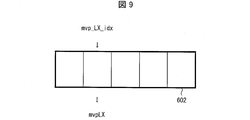
- FIG. 9 is a conceptual diagram showing an example of vector candidates.
- a predicted vector list 602 illustrated in FIG. 9 is a list including a plurality of vector candidates derived by the vector candidate deriving unit 3033.
- five rectangles arranged in a line on the left and right indicate areas indicating prediction vectors, respectively.
- the downward arrow directly below the second mvp_LX_idx from the left end and mvpLX below the mvp_LX_idx indicate that the prediction vector index mvp_LX_idx is an index that refers to the vector mvpLX in the prediction parameter memory 307.
- the vector candidate is generated based on the vector related to the block referred to by the vector candidate selection unit 3034.
- the block referred to by the vector candidate selection unit 3034 is a block for which decoding processing has been completed, and may be a block in a predetermined range from the decoding target block (for example, an adjacent block).
- the adjacent block is a block spatially adjacent to the decoding target block, for example, the left block, the upper block, or a block temporally adjacent to the decoding target block, for example, the same position as the decoding target block, at the display time. Includes blocks obtained from different blocks.
- the addition unit 3035 adds the prediction vector mvpLX input from the AMVP prediction parameter derivation unit 3032 and the difference vector mvdLX input from the inter prediction parameter decoding control unit 3031 to calculate a motion vector mvLX.
- the adding unit 3035 outputs the calculated motion vector mvLX to the predicted image generation unit 308 (FIG. 5).
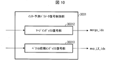
- FIG. 10 is a schematic diagram illustrating a configuration of the inter prediction parameter decoding control unit 3031 according to the present embodiment.
- the inter prediction parameter decoding control unit 3031 includes an additional prediction flag decoding unit 30311, a merge index decoding unit 30312, a vector candidate index decoding unit 30313, and a partition mode decoding unit, a merge flag decoding unit, an inter prediction flag decoding unit, not shown. It includes a picture index decoding unit, a vector difference decoding unit, and the like.
- the partition mode decoding unit, the merge flag decoding unit, the merge index decoding unit, the inter prediction flag decoding unit, the reference picture index decoding unit, the vector candidate index decoding unit 30313, and the vector difference decoding unit are respectively divided mode part_mode, merge flag merge_flag, merge The index merge_idx, inter prediction flag inter_pred_idc, reference picture index refIdxLX, prediction vector index mvp_LX_idx, and difference vector mvdLX are decoded.
- FIG. 11 is a schematic diagram illustrating a configuration of the inter predicted image generation unit 309 according to the present embodiment.
- the inter prediction image generation unit 309 includes a motion compensation unit 3091 and a weight prediction unit 3094.
- the motion compensation unit 3091 Based on the prediction list use flag predFlagLX, the reference picture index refIdxLX, and the motion vector mvLX input from the inter prediction parameter decoding unit 303, the motion compensation unit 3091 refers to the reference specified by the reference picture index refIdxLX from the reference picture memory 306.
- a motion compensated image is generated by reading out a block at a position shifted by the motion vector mvLX, starting from the position of the decoding target block of the picture.
- a motion compensation image is generated by applying a filter for generating a pixel at a decimal position called a motion compensation filter.
- predSamplesL0 the motion compensation image for L0 prediction
- predSamplesL1 the motion compensation image for L1 prediction
- predSamplesLX the motion compensation image for L1 prediction
- the weight prediction unit 3094 generates a prediction picture block P (prediction image) by multiplying the input motion displacement image predSamplesLX by a weight coefficient.
- the input motion displacement images predSamplesLX are images on which residual prediction is performed when residual prediction is performed.
- the input motion displacement image predSamplesLX (LX is L0 or L1) is set to the number of pixel bits. The following formula is processed.
- predSamples [x] [y] Clip3 (0, (1 ⁇ bitDepth)-1, (predSamplesLX [x] [y] + offset1) >> shift1)
- shift1 14-bitDepth
- offset1 1 ⁇ (shift1-1).
- predFlagL0 or predFlagL1 are 1 (in the case of bi-prediction) and weight prediction is not used
- the input motion displacement images predSamplesL0 and predSamplesL1 are averaged to obtain the number of pixel bits.
- the following formula is processed.
- predSamples [x] [y] Clip3 (0, (1 ⁇ bitDepth)-1, (predSamplesL0 [x] [y] + predSamplesL1 [x] [y] + offset2) >> shift2)
- shift2 15-bitDepth
- offset2 1 ⁇ (shift2-1).
- the weight prediction unit 3094 when performing weight prediction, derives the weight prediction coefficient w0 and the offset o0 from the encoded data, and performs the processing of the following equation.
- predSamples [x] [y] Clip3 (0, (1 ⁇ bitDepth)-1, ((predSamplesLX [x] [y] * w0 + 2log2WD-1) >> log2WD) + o0)
- log2WD is a variable indicating a predetermined shift amount.
- the weight prediction unit 3094 when performing weight prediction, derives the heavy weight prediction coefficients w0, w1, o0, o1 from the encoded data, and performs the processing of the following equation.
- predSamples [x] [y] Clip3 (0, (1 ⁇ bitDepth)-1, (predSamplesL0 [x] [y] * w0 + predSamplesL1 [x] [y] * w1 + ((o0 + o1 + 1) ⁇ log2WD)) >> (log2WD + 1)) ⁇ Motion vector decoding process>
- predSamplesL0 [x] [y] * w0 + predSamplesL1 [x] [y] * w1 + ((o0 + o1 + 1) ⁇ log2WD)) >> (log2WD + 1))
- the motion vector decoding process includes a process of decoding syntax elements related to inter prediction (also referred to as motion syntax decoding process) and a process of deriving a motion vector ( Motion vector derivation process).
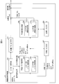
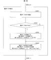
- FIG. 15 is a flowchart illustrating a flow of inter prediction syntax decoding processing performed by the inter prediction parameter decoding control unit 3031. In the following description in the description of FIG. 15, each process is performed by the inter prediction parameter decoding control unit 3031 unless otherwise specified.
- merge_flag! 0 is true (Y in S102)
- merge index merge_idx is decoded in S103, and the process proceeds to the motion vector derivation process (S201) in merge mode (FIG. 18A).
- inter prediction flag inter_pred_idc is decoded in S104
- the reference picture index refIdxL0 is decoded in S105
- the syntax mvdL0 of the difference vector is decoded in S106
- S107 The prediction vector index mvp_L0_idx is decoded.
- the reference picture index refIdxL1 is decoded.
- the difference vector syntax mvdL1 is decoded.
- the prediction vector index mvp_L1_idx is decoded.
- inter prediction flag inter_pred_idc is 0, that is, indicates L0 prediction (PRED_L0), the processing of S108 to S110 is not necessary.
- the inter prediction flag inter_pred_idc is 1, that is, indicates L1 prediction (PRED_L1), the processing of S105 to S107 is unnecessary.
- the inter prediction flag inter_pred_idc is 2, that is, indicates bi-prediction (PRED_B), steps S105 to S110 are executed.
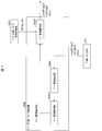
- FIG. 16 is a flowchart showing more specifically the difference vector decoding process in steps S106 and S109 described above. So far, the horizontal and vertical components of the motion vector and the difference vector mvdLX have not been distinguished from each other, and are expressed as mvLX and mvdLX. Here, in order to clarify that the syntax of the horizontal component and the vertical component is required and that the processing of the horizontal component and the vertical component is necessary, using [0] and [1], Each component is indicated.
- step S10611 the syntax mvdAbsVal [0] indicating the horizontal motion vector difference absolute value is decoded from the encoded data.
- step S10615 the syntax mvdAbsVal [1] indicating the absolute value of the vertical motion vector difference is decoded.
- each of the motion vector difference absolute value mvdAbsVal and the motion vector difference code mvd_sign_flag is represented by a vector consisting of ⁇ horizontal component, vertical component ⁇ , the horizontal component is accessed with [0], and the vertical component is accessed with [1]. Yes.
- the vertical component may be [0] and the horizontal component may be [1].
- the vertical component is processed next to the horizontal component, but the processing order is not limited to this.
- the vertical component may be processed first and the horizontal component processed later (the same applies hereinafter).
- FIG. 17 is a flowchart illustrating an example in which the difference vector is decoded in steps S106 and S109 by a method different from the process illustrated in FIG.
- the steps already described in FIG. 16 are denoted by the same reference numerals in FIG.
- FIG. 17 differs from FIG. 16 in that the motion vector accuracy flag mvd_dequant_flag is further decoded.
- nonZeroMV 0? Is judged.
- variable nonZeroMV can be derived as follows.
- the motion vector accuracy flag mvd_dequant_flag is used to switch the accuracy of the motion vector. Further, when the flag is a flag for selecting whether or not the motion vector accuracy is full pel, it may be written as integer_mv_flag (may be described).
- FIG. 18 is a flowchart showing the flow of motion vector derivation processing performed by the inter prediction parameter decoding unit 303 according to this embodiment.
- FIG. 18A is a flowchart showing the flow of motion vector derivation processing in the merge prediction mode.
- the merge candidate derivation unit 30361 derives a merge candidate list mergeCandList.
- a differential motion vector mvdLX is derived from the decoded syntaxes mvdAbsVal and mv_sign_flag, and the motion vector mvLX is derived by adding the differential motion vector mvdLX to the prediction vector mvpLX.
- mvdAbsVal [0], mvdAbsVal [1], etc. and [0], [1] are used to distinguish the horizontal component from the vertical component. Without distinguishing components, it is simply described as mvdAbsVal. Actually, since the motion vector has a horizontal component and a vertical component, the processing described without distinguishing the components may be executed in order for each component.
- FIG. 18B is a flowchart showing the flow of motion vector derivation processing in the AMVP mode.
- the vector candidate deriving unit 3033 derives a motion vector predictor list mvpListLX.
- the inter prediction parameter decoding control unit 3031 derives a difference vector mvdLX.
- the vector candidate selection unit 3034 may round the selected prediction vector.
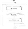
- FIG. 19 is a flowchart more specifically showing the difference vector deriving process in step S303 described above.
- the difference vector derivation process includes the following two processes. Inverse quantization process (PS_DQMV): A value decoded from encoded data, and the motion vector difference absolute value mvdAbsVal (quantized value), which is the quantized value, is inversely quantized to a specific accuracy (for example, described later) Processing to derive the motion vector difference absolute value mvdAbsVal (basic vector accuracy).
- Sign addition process PS_SIGN: A process for determining the sign of the derived motion vector difference absolute value mvdAbsVal and deriving the motion vector difference mvdLX.
- each process is performed by the inter prediction parameter decoding control unit 3031 unless otherwise specified.
- a motion vector scale shiftS which is a parameter for designating motion vector accuracy, is derived in S3031, and in S3032, it is determined whether or not motion vector scale> 0. If the motion vector scale> 0 is true, that is, shiftS> 0 (Y in S3032), in S3033, for example, the difference vector is inversely quantized by bit shift processing using shiftS.
- step S ⁇ b> 3034 a difference vector signing process is performed, and the process proceeds to step S ⁇ b> 3041.
- FIG. 20 is a flowchart more specifically showing the prediction vector round process in step S304 described above.
- each process is performed by the vector candidate selection unit 3034 unless otherwise specified.
- a motion vector scale is derived in S3041, and a motion vector scale> 0 is determined in S3042. If the motion vector scale> 0 is true (Y in S3042), that is, if the difference vector is inversely quantized by the motion vector scale, the predicted motion vector mvpLX is rounded based on the motion vector scale in S3043.
- mvpLX round (mvpLX, shiftS) May be rounded (processing PS_PMVROUND).
- round (mvpLX, shiftS) represents a function that performs round processing using shiftS on the predicted motion vector mvpLX.
- the round process may use a formula (SHIFT-1) to (SHIFT-4), which will be described later, and the predicted motion vector mvpLX may be a value in 1 ⁇ shiftS units (separate value).
- a motion vector mvLX is derived from the prediction vector mvpLX and the difference vector mvdLX.
- the motion vector scale> 0 is false (N in S3042)
- the predicted motion vector mvpLX is not rounded but proceeds to S305, and the motion vector mvLX is derived.
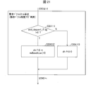
- FIG. 21 is a flowchart showing more specifically the motion vector scale derivation process in S3031 (see FIG. 19) and S3041 (see FIG. 20) described above.
- the process of S3041 is specifically illustrated for convenience of explanation, but the process shown in FIG. 21 may be applied to S3031.
- each process is performed by the inter prediction parameter decoding control unit 3031 unless otherwise specified.
- the value of mvBaseAccu is 2, for example. It progresses to S3042 after S304112.
- the accuracy of the motion vector is reduced when mvd_dequant_flag is 1, and the accuracy of the motion vector is maintained when mvd_dequant_flag is 0.
- the motion vector accuracy may be reduced, and 1 may maintain the motion vector accuracy. That is, for the flags shown in this specification, the numerical values and the contents indicated by the flags can be arbitrarily combined.
- the motion vector accuracy is switched with reference to the motion vector accuracy flag, so that a motion vector having more appropriate accuracy can be used.
- the amount of codes increases, and the encoding efficiency may not be improved as expected.
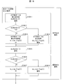
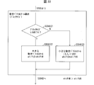
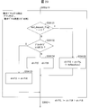
- FIG. 22 is a flowchart showing more specifically the motion vector scale derivation processing in S3031 (see FIG. 19) and S3041 (see FIG. 20) described above. In FIG. 22, for convenience of explanation, the process of S3041 is specifically illustrated, but the process shown in FIG. 22 may be applied to S3031.
- each process is performed by the inter prediction parameter decoding control unit 3031 unless otherwise specified.
- shiftS (blkW ⁇ TH)? shiftM: shiftN (Formula P1A)
- blkW + blkH ⁇ TH may be used instead of blkW ⁇ TH as a block size threshold value determination.
- the branch determination may use ⁇ (below) regardless of ⁇ (greater than), or may have an equivalent configuration in which the branches of Y and N are reversed as> and ⁇ . Note that the above-described changes may be applied as appropriate in other processes in this specification.
- the motion vector scale is derived so that the value of the motion vector scale is smaller (the motion vector accuracy is higher) as the block size is larger according to the block size.
- the number of block size classifications is not limited to 2, and may be 3 or more. .
- the accuracy of the difference vector can be switched according to the block size. For example, when the block size is larger than a predetermined value, it can be switched to a high-precision vector, and when the block size is smaller than a predetermined value, it can be switched to a low-precision motion vector.
- a motion vector with more appropriate accuracy can be used.
- the accuracy of the difference vector can be switched without using the motion vector accuracy flag. Therefore, it is not necessary to encode and decode the motion vector accuracy flag, and the code amount of the encoded data is reduced. This can also improve the encoding efficiency.
- FIG. 23 is a flowchart showing more specifically the motion vector scale derivation processing in S3031 and S3041 described above.
- the process of S3041 is specifically illustrated for convenience of explanation, but the process shown in FIG. 23 may be applied to S3031.
- the block size classification may be classified into three or more, regardless of the two classifications.
- the accuracy of the motion vector is determined with reference to both the block size and the motion vector accuracy flag, a motion vector having a more appropriate accuracy can be used.
- the motion vector accuracy flag indicates the accuracy of the motion vector in integer accuracy (low accuracy)
- the accuracy of the difference vector is set to integer accuracy (low accuracy) regardless of the block size.
- the motion vector accuracy flag indicates the accuracy of the motion vector with decimal accuracy (high accuracy)
- the accuracy of the difference vector can be further switched according to the block size.
- the inter prediction parameter decoding unit 303 (motion vector deriving unit) derives a motion vector by adding or subtracting a difference vector to or from a prediction vector for each prediction block.
- the inter prediction parameter decoding unit 303 switches the accuracy of the motion vector derived for the prediction block (particularly the shift value used for deriving the motion vector difference absolute value) according to the size of the prediction block.
- the motion vector derived by the above-described motion vector derivation processing can be expressed by the following equation.
- the inverse quantization of the difference vector mvdLX shown in the above section may be performed on the motion vector difference absolute value.
- the motion vector difference absolute value mvdAbsVal may be inversely quantized to perform a coding process.
- the variables mvdAbsVal and mvdLX are represented by a configuration that is updated. However, in order to clarify the processing, they can be represented as follows by using “′”.
- the absolute value of the difference motion vector before dequantization (quantized) may be represented by qmvd instead of mvdAbsVal.
- round processing In the above description, the round process is mentioned. A specific example of the round process does not limit the present embodiment.
- round (mvpLX) (mvpLX >> shiftS ⁇ shiftS) ... (SHIFT-1) May be used.
- the variable in round () is not limited to mvpLX.
- offset value offsetS 1 ⁇ (shiftS-1)
- round (mvpLX) ((mvpLX + offsetS) >> shiftS) ⁇ shiftS ... (SHIFT-2) It is good.
- round (mvpLX) mvpLX> 0?
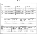
- FIG. 24A to 24C are tables showing the relationship between the basic vector accuracy and the parameter (shiftS) indicating the motion vector accuracy set (switched) by the block size of the target block.
- the inter prediction parameter decoding control unit 3031 may perform the above-described processing from S304121 to S304123 shown in FIG. 22 as in the examples shown in (a) to (c) of FIG.
- the concept of “basic vector” is introduced, and a parameter that specifies the accuracy of this basic vector is represented by mvBaseAccu.
- the “basic vector” is virtually decoded with the accuracy of 1 ⁇ mvBaseAccu.
- the name “basic vector” is merely for convenience, and “basic vector” is merely introduced as a reference for specifying the accuracy of the motion vector.
- FIG. 24 (a) is a table showing the relationship between the block size of the target block, the basic vector accuracy, and the parameter shiftS indicating the motion vector accuracy when the motion vector accuracy is switched between two values.
- mvBaseAccu 3
- the accuracy of the basic vector is 1/8 pel.
- shiftS 0
- the motion vector accuracy is 1/8 pel.
- FIG. 24B is a table showing the relationship between the block size of the target block, the basic vector accuracy, and the parameter (shiftS) indicating the motion vector accuracy when the motion vector accuracy is switched to three values.
- FIG. 24C is a table showing the relationship among the block size of the target block, the basic vector accuracy, and the parameter (shiftS) indicating the motion vector accuracy when the motion vector accuracy is switched to five values.
- the inter prediction parameter decoding control unit 3031 may be configured to perform inverse quantization by a product of the motion vector quantization step size MVQStep instead of the left shift by the motion vector scale shiftS. That is, inverse quantization may be performed by the following equation instead of the equation (Scale).
- MVQStep mvdAbsVal * MVQStep expression (QStep)
- the accuracy of the basic motion vector is 1/8
- the accuracy of the motion vector to be encoded is 1/8
- the quantization step MVQStep is 2, it is encoded.
- the accuracy of the motion vector (MVStep) is 1/4. Therefore, if the accuracy of the basic motion vector is 1 / mvBaseAccu, the accuracy MVStep of the motion vector to be encoded in the quantization step MVQStep is 1 / mvBaseAccu * MVQStep.
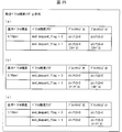
- FIG. 25 (Example of motion vector accuracy switched using block size and motion vector accuracy flag)
- mvd_dequant_flag a specific example of motion vector accuracy (derivation processing PS_P1B) that is switched using the block size and the motion vector accuracy flag mvd_dequant_flag
- FIGS. 25A to 25C an example in which the basic vector accuracy is 1/16 is shown, but any value can be applied as the value of the basic vector accuracy.
- the inter prediction parameter decoding control unit 3031 may perform the above-described processing from S304131 to S304135 shown in FIG. 23 as in the examples shown in (a) to (c) of FIG.
- shiftS 0 is set, and the motion vector accuracy MVStep is 1. / 16pel.
- shiftS 2 is set, and the motion vector accuracy is 1/4 pel.
- the inter prediction parameter decoding control unit 3031 may derive shiftS based on QP (Quantization Parameter) that is a quantization parameter instead of the block size of the target block (derivation).
- QP Quantization Parameter
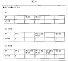
- FIG. 26A to 26C are tables showing parameters (shiftS) indicating motion vector accuracy set (switched) by QP.
- the inter prediction parameter decoding control unit 3031 may perform the difference vector derivation process as in the examples illustrated in (a) to (c) of FIG.
- the basic vector accuracy value is not particularly mentioned, but an arbitrary basic vector accuracy value can be used.
- 26 (a), (b), and (c) show examples in which two, three, and five values are switched according to QP, respectively, the number of switching (number of QP classifications) is not limited to this. .
- the threshold value used for QP classification is not limited to the example shown in the figure.
- FIG. 26 (a) is a table showing the relationship between QP and motion vector accuracy (shiftS) when the motion vector accuracy is switched between two values.
- shiftS motion vector accuracy
- 26B is a table showing the relationship between the QP and the parameter (shiftS) indicating the motion vector accuracy when the motion vector accuracy is switched to three values.
- shiftS the parameter
- FIG. 26C is a table showing the correspondence between the QP and the parameter (shiftS) indicating the motion vector accuracy when the motion vector accuracy is switched to five values.
- the accuracy of the motion vector derived with respect to the prediction block is switched according to the size of the quantization parameter, so that a prediction image can be generated using a motion vector having appropriate accuracy.
- the inter prediction parameter decoding control unit 3031 may be configured to derive MVQStep instead of the above-described shiftS as the motion vector accuracy according to the block size of the target block.
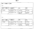
- FIGS. 27A and 27B are tables showing motion vector accuracy (shiftS) set (switched) by the QP and the motion vector accuracy flag.
- the inter prediction parameter decoding control unit 3031 may perform the difference vector derivation process as in the example illustrated in FIGS.
- the motion vector accuracy flag mvd_dequant_flag 1 (other than 0)
- FIG. 27B shows an example in which the motion vector scale shiftS is derived according to QP even when the motion vector accuracy flag is 1 (other than 0).
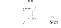
- the processing described below is performed by the inter prediction parameter decoding control unit 3031 unless otherwise specified.
- the quantized difference vector is equivalent to the value mvdAbsVal of the difference vector absolute value at the time point obtained by decoding the syntax of the encoded data (the time point before inverse quantization), and the absolute value of qmvd is mvdAbsVal.
- the difference vector quantization value qmvd can be either positive or negative in order to clarify the image regardless of whether the difference vector is negative or positive.
- FIG. 28 is a graph showing the relationship between the quantized difference vector and the dequantized difference vector in this processing example.
- the horizontal axis of the graph shown in FIG. 28 is qmvd which is a quantized difference vector (decoded difference vector quantized and encoded by the encoding device and not dequantized, that is, ,
- the inter prediction parameter decoding control unit 3031 performs an inverse quantization process on the quantized difference vector qmvd as shown in the graph of FIG.
- the addition unit 3035 derives a motion vector by adding or subtracting the dequantized difference vector to the prediction vector.
- mvdLX mvdAbsVal * (1-2 * mv_sign_flag)
- mvLX round (mvpLX) + mvdLX Derived by
- the inter prediction parameter decoding control unit 3031 performs inverse quantization of the quantized motion vector according to the magnitude relationship between the quantized motion vector difference decoded from the encoded data and a predetermined value (dTH). Switch the accuracy of processing.
- the accuracy of the motion vector is set high, and when the absolute value of the difference vector mvd is large, the accuracy of the motion vector is set low.
- the quantized difference vector qmvd is changed compared to when the absolute value of the difference vector mvd is far from the vicinity of the zero point.
- the inverse quantization difference vector mvd changes small.
- the inter prediction parameter decoding control unit 3031 has a predetermined inclination with respect to the quantized difference vector qmvd.
- the predetermined inclination may be 1, for example.
- mvdAbsVal is the absolute value of the difference vector after inverse quantization
- K represents a predetermined proportional coefficient.
- the product by K may be realized by a left shift by log2 (K).
- the quantized difference vector qmvd is 16 or more (the motion vector accuracy is equivalent to 2 pel or more)
- the quantization difference vector qmvd is 16 or more (the motion vector accuracy is equivalent to 1 pel or more)
- the inter-prediction parameter decoding control unit 3031 performs inverse quantization specified by the gradient obtained by the above. If the quantized difference vector qmvd is greater than or equal to the threshold value dTH (or greater than dTH), 1 ⁇ shiftS2 The inter-prediction parameter decoding control unit 3031 performs inverse quantization specified by the gradient obtained by the above.
- shiftS1 and shiftS2 may or may not be equal to each other.
- the motion vector accuracy flag mvd_dequant_flag 0 is satisfied
- the predetermined threshold value qmvd 16 (equivalent to 1 pel) or more
- shiftS 2 bits
- a predicted image can be generated using a motion vector with more appropriate accuracy. For this reason, since prediction accuracy improves, encoding efficiency improves.
- the quantized value of the quantized difference vector indicates whether the accuracy of the inverse quantization process for the difference vector is the third accuracy or the fourth accuracy. Switch according to. At least one of the first accuracy and the second accuracy is higher than the third accuracy and the fourth accuracy.
- the inter prediction parameter decoding control unit 3031 sets the motion vector accuracy to the basic vector accuracy 1/8 Set to.
- a predicted image can be generated using a motion vector with more appropriate accuracy. For this reason, since prediction accuracy improves, encoding efficiency improves.
- the vector candidate selection unit 3034 performs round processing on the inversely quantized difference vector.
- a motion vector is derived by adding or subtracting to the prediction vector.
- the motion vector accuracy of mvpLX is reduced to the accuracy of 1 ⁇ shiftS units.
- the process of deriving mvdLX from mvdAbsVal is as described for the sign assignment process PS_SIGN.
- the inter prediction parameter decoding control unit 3031 converts the difference vector obtained by inverse quantization according to the motion vector accuracy flag and the quantized difference vector to the prediction vector subjected to the round processing by the vector candidate selection unit 3034.
- a motion vector is derived by addition or subtraction.
- mvdAbsVal qmvd ⁇ shiftA Derives mvdAbs.
- the motion vector accuracy of mvpLX is lowered to the accuracy of 1 ⁇ shiftA units.
- the process of deriving mvdLX from mvdAbsVal is as described for the sign assignment process PS_SIGN.
- the quantized difference vector qmvd is less than the predetermined value dTH
- the motion vector mvLX is the sum of the prediction vector mvpLX and the difference vector mvdLX.
- mvLX round (mvpLX, shiftS) + mvdLX Is derived by
- the motion vector accuracy of mvpLX is reduced to the accuracy of 1 ⁇ shiftS units.
- the process of deriving mvdLX from mvdAbsVal is as described for the sign assignment process PS_SIGN.
- the inter prediction parameter decoding control unit 3031 performs inverse operation on the difference vector with accuracy other than the highest accuracy among the first accuracy, the second accuracy, the third accuracy, and the fourth accuracy.
- the addition unit 3035 derives a motion vector by adding or subtracting the dequantized difference vector to the prediction vector subjected to the round process by the vector candidate selection unit 3034. .
- round (mvpLX, shiftA1) the motion vector accuracy of mvpLX is reduced to the accuracy of 1 ⁇ shiftA1 unit.
- mvd_dequant_flag 1
- mvdAbsVal predetermined value dTHA ⁇ shiftA1 + (qmvd-dTHA) ⁇ shiftA2 Yields mvdAbsVal.
- round (mvpLX, shiftA2) the motion vector accuracy of mvpLX is reduced to the accuracy of 1 ⁇ shiftA2.
- the process of deriving mvdLX from mvdAbsVal is as described for the sign assignment process PS_SIGN.
- the quantized difference vector qmvd is less than the predetermined value dTH
- the motion vector mvLX is the sum of the prediction vector mvpLX and the difference vector mvdLX.
- mvLX round (mvpLX, shiftS) + mvdLX Is derived by
- the motion vector accuracy of mvpLX is reduced to the accuracy of 1 ⁇ shiftS units.
- the process of deriving mvdLX from mvdAbsVal is as described for the sign assignment process PS_SIGN.
- FIG. 29 is a flowchart showing more specifically the motion vector scale derivation processing in S3031 (see FIG. 19) and S3041 (see FIG. 20) described above.
- the process of S3041 is specifically illustrated for convenience of explanation, but the process shown in FIG. 22 may be applied to S3031.
- FIG. 30 is a block diagram showing a specific configuration of the motion compensation unit 3091.
- the motion compensation unit 3091 includes a motion vector application unit 30911, a motion compensation filter unit (filter unit) 30912, and a filter coefficient memory 30913.
- the motion vector application unit 3091 is designated by the reference picture index refIdxLX from the reference picture memory 306 based on the prediction list use flag predFlagLX, the reference picture index refIdxLX, and the motion vector mvLX input from the inter prediction parameter decoding unit 303.
- a motion vector applied image is generated by reading a block at a position shifted by the motion vector mvLX, starting from the position of the decoding target block of the reference picture.
- the motion vector applied image also has 1 / M pixel accuracy.
- the motion compensation filter 30912 uses the filter coefficient mcFilter [i] [k] (where i is an integer between 0 and M-1, and k is an integer between 0 and Ntaps-1). Is applied to a motion vector-applied image to distinguish between the above-described motion compensated images (predSamplesL0 for a motion compensated image for L0 prediction and predSamplesL1 for a motion compensated image for L1 prediction). If not, generate predSamplesLX).
- the motion compensation filter 30912 does not act on the motion vector applied image, and the motion vector applied image becomes the motion compensated image as it is.
- the filter coefficient memory 30913 stores motion compensation filter coefficients decoded from the encoded data. More specifically, the filter coefficient memory 30913 is a filter coefficient mcFilter [i] [k] used by the motion compensation filter 30912 (where i is an integer from 0 to M ⁇ 1, and k is from 0 to Ntaps ⁇ 1). Among the following integers), at least some of the filter coefficients relating to i are stored.
- FIG. 31 is a diagram illustrating an example of filter coefficients according to the present embodiment.
- the accuracy of the motion vector is 1/16 pixel accuracy. That is, when the total number of phases is M, the accuracy of the motion vector is 1 / M pixel accuracy.
- the coefficient position means the relative position of the pixel on which the filter coefficient is applied.
- the total number of filter coefficients is a value obtained by multiplying the number of taps of the filter and the number of phases (that is, the reciprocal of the accuracy of the motion vector).
- the filter coefficient mcFilter [i] [k] used by the motion compensation filter unit (filter unit) 30912 includes a filter coefficient mcFilter [p] [k] (p ⁇ i) and a filter coefficient mcFilter [q] [k] (q The filter coefficient calculated using ⁇ i) may be included. Details of a calculation example of the filter coefficient mcFilter [i] [k] are as follows.
- the motion compensation filter unit 30912 calculates a filter coefficient of another phase (here, odd number) from a filter coefficient of a part (even number here) phase, and uses the calculated filter coefficient.
- a filter coefficient of another phase here, odd number
- even-phase filter coefficients are shown with an underline.
- the filter coefficient memory 30913 stores even-numbered phase filter coefficients.
- filter coefficients of odd-numbered phases may be stored in the filter coefficient memory 30913, and the stored filter coefficients may be used as the filter coefficients by the motion compensation filter unit 30912.
- the division described by / 2 may be >> 1.
- the following table may be used as mcFilterC.
- FIG. 32B shows an example in which the motion compensation filter unit 30912 calculates a filter coefficient of another phase (even phase) from a part (here, odd phase) of filter coefficients.
- the odd phase filter coefficients are shown with an underline.
- the filter coefficient memory 30913 stores odd-numbered phase filter coefficients.
- / 2 may be >> 1.
- the following table may be used as mcFilterC.
- mcFilterC [] ⁇ ⁇ 0, 0, 0, 64, 0, 0, 0, 0 ⁇ , ⁇ 0, 1, -3, 63, 4, -2, 1, 0 ⁇ , ⁇ -1, 3, -8, 60, 13, -4, 1, 0 ⁇ , ⁇ -1, 4, -11, 52, 26, -8, 3, -1 ⁇ , ⁇ -1, 4, -11, 45, 34, -10, 4, -1 ⁇ , ⁇ -1, 4, -10, 34, 45, -11, 4, -1 ⁇ , ⁇ -1, 3, -8, 26, 52, -11, 4, -1 ⁇ , ⁇ 0, 1, -4, 13, 60, -8, 3, -1 ⁇ , ⁇ 0, 1, -2, 4, 63, -3, 1, 0 ⁇ ⁇
- even partial filter coefficients of some phases may be stored in the filter coefficient memory 30913, and the motion compensation filter unit 30912 may use the stored filter coefficients as filter coefficients.
- mcFilter [i] [k] ((Nw) * mcFilter [i0] [k] + w * mcFilter [i1] [k]) >> log (N)
- i0 (i / N) * N
- i1 i0 + N
- w (i% N)
- N is an integer of 2 or more.
- the following structures may be sufficient.
- FIG. 12 is a block diagram illustrating a configuration of the image encoding device 11 according to the present embodiment.
- the image encoding device 11 includes a prediction image generation unit 101, a subtraction unit 102, a DCT / quantization unit 103, an entropy encoding unit 104, an inverse quantization / inverse DCT unit 105, an addition unit 106, a prediction parameter memory (prediction parameter storage) Unit, frame memory) 108, reference picture memory (reference image storage unit, frame memory) 109, coding parameter determination unit 110, prediction parameter coding unit 111, and residual storage unit 313 (residual recording unit). Is done.
- the prediction parameter encoding unit 111 includes an inter prediction parameter encoding unit 112 and an intra prediction parameter encoding unit 113.
- the predicted image generation unit 101 generates a predicted picture block P for each block which is an area obtained by dividing the picture for each viewpoint of the layer image T input from the outside.
- the predicted image generation unit 101 reads the reference picture block from the reference picture memory 109 based on the prediction parameter input from the prediction parameter encoding unit 111.
- the prediction parameter input from the prediction parameter encoding unit 111 is, for example, a motion vector or a displacement vector.
- the predicted image generation unit 101 reads the reference picture block of the block at the position indicated by the motion vector or the displacement vector predicted from the encoding target block.
- the prediction image generation unit 101 generates a prediction picture block P using one prediction method among a plurality of prediction methods for the read reference picture block.
- the predicted image generation unit 101 outputs the generated predicted picture block P to the subtraction unit 102. Note that since the predicted image generation unit 101 performs the same operation as the predicted image generation unit 308 already described, details of generation of the predicted picture block P are omitted.
- the predicted image generation unit 101 minimizes an error value based on a difference between a signal value for each pixel of a block included in an image and a signal value for each corresponding pixel of the predicted picture block P. Select the prediction method to use. The method for selecting the prediction method is not limited to this.
- the multiple prediction methods are intra prediction, motion prediction, and merge prediction.
- Motion prediction is prediction between display times among the above-mentioned inter predictions.
- the merge prediction is a prediction that uses the same reference picture block and prediction parameter as a block that has already been encoded and is within a predetermined range from the encoding target block.
- the prediction image generation unit 101 When the intra prediction is selected, the prediction image generation unit 101 outputs a prediction mode IntrapredMode indicating the intra prediction mode used when generating the prediction picture block P to the prediction parameter encoding unit 111.
- the predicted image generation unit 101 when selecting motion prediction, stores the motion vector mvLX used when generating the predicted picture block P in the prediction parameter memory 108 and outputs the motion vector mvLX to the inter prediction parameter encoding unit 112.
- the motion vector mvLX indicates a vector from the position of the encoding target block to the position of the reference picture block when the predicted picture block P is generated.
- the information indicating the motion vector mvLX may include information indicating a reference picture (for example, a reference picture index refIdxLX, a picture order number POC), and may represent a prediction parameter.
- the predicted image generation unit 101 outputs a prediction mode predMode indicating the inter prediction mode to the prediction parameter encoding unit 111.
- the prediction image generation unit 101 selects merge prediction
- the prediction image generation unit 101 outputs a merge index merge_idx indicating the selected reference picture block to the inter prediction parameter encoding unit 112. Further, the predicted image generation unit 101 outputs a prediction mode predMode indicating the merge prediction mode to the prediction parameter encoding unit 111.
- the predicted image generation unit 101 may have a configuration for generating a motion compensation filter coefficient referred to by the motion compensation unit 3091 provided in the image decoding device 31.
- the predicted image generation unit 101 may have a configuration corresponding to the motion vector accuracy switching described in the image decoding device 31. That is, the predicted image generation unit 101 may switch the accuracy of the motion vector according to the block size, QP, and the like.
- the image decoding device 31 may be configured to encode a motion vector accuracy flag mvd_dequant_flag that is referred to when the accuracy of the motion vector is switched.
- the subtraction unit 102 subtracts the signal value of the prediction picture block P input from the prediction image generation unit 101 for each pixel from the signal value of the corresponding block of the layer image T input from the outside, and generates a residual signal. Generate.
- the subtraction unit 102 outputs the generated residual signal to the DCT / quantization unit 103 and the encoding parameter determination unit 110.
- the DCT / quantization unit 103 performs DCT on the residual signal input from the subtraction unit 102 and calculates a DCT coefficient.
- the DCT / quantization unit 103 quantizes the calculated DCT coefficient to obtain a quantization coefficient.
- the DCT / quantization unit 103 outputs the obtained quantization coefficient to the entropy coding unit 104 and the inverse quantization / inverse DCT unit 105.
- the entropy encoding unit 104 receives a quantization coefficient from the DCT / quantization unit 103 and receives an encoding parameter from the encoding parameter determination unit 110.
- input encoding parameters include codes such as a reference picture index refIdxLX, a prediction vector index mvp_LX_idx, a difference vector mvdLX, a prediction mode predMode, and a merge index merge_idx.
- the entropy encoding unit 104 may be configured to perform a process corresponding to the nonlinear inverse quantization process described in the image decoding device 31, that is, a nonlinear quantization process for the difference vector, before encoding the difference vector mvdLX. Good.
- the entropy encoding unit 104 generates an encoded stream Te by entropy encoding the input quantization coefficient and encoding parameter, and outputs the generated encoded stream Te to the outside.
- the inverse quantization / inverse DCT unit 105 inversely quantizes the quantization coefficient input from the DCT / quantization unit 103 to obtain a DCT coefficient.
- the inverse quantization / inverse DCT unit 105 performs inverse DCT on the obtained DCT coefficient to calculate a decoded residual signal.
- the inverse quantization / inverse DCT unit 105 outputs the calculated decoded residual signal to the addition unit 106.
- the adding unit 106 adds the signal value of the predicted picture block P input from the predicted image generation unit 101 and the signal value of the decoded residual signal input from the inverse quantization / inverse DCT unit 105 for each pixel, and refers to Generate a picture block.
- the adding unit 106 stores the generated reference picture block in the reference picture memory 109.
- the prediction parameter memory 108 stores the prediction parameter generated by the prediction parameter encoding unit 111 at a predetermined position for each picture and block to be encoded.
- the reference picture memory 109 stores the reference picture block generated by the adding unit 106 at a predetermined position for each picture and block to be encoded.
- the encoding parameter determination unit 110 selects one set from among a plurality of sets of encoding parameters.
- the encoding parameter is a parameter to be encoded that is generated in association with the above-described prediction parameter or the prediction parameter.
- the predicted image generation unit 101 generates a predicted picture block P using each of these sets of encoding parameters.
- the encoding parameter determination unit 110 calculates a cost value indicating the amount of information and the encoding error for each of a plurality of sets.
- the cost value is, for example, the sum of a code amount and a square error multiplied by a coefficient ⁇ .
- the code amount is the information amount of the encoded stream Te obtained by entropy encoding the quantization error and the encoding parameter.
- the square error is the sum between pixels regarding the square value of the residual value of the residual signal calculated by the subtracting unit 102.
- the coefficient ⁇ is a real number larger than a preset zero.
- the encoding parameter determination unit 110 selects a set of encoding parameters that minimizes the calculated cost value. As a result, the entropy encoding unit 104 outputs the selected set of encoding parameters to the outside as the encoded stream Te, and does not output the set of unselected encoding parameters.
- the prediction parameter encoding unit 111 derives a prediction parameter used when generating a prediction picture based on the parameter input from the prediction image generation unit 101, and encodes the derived prediction parameter to generate a set of encoding parameters. To do.
- the prediction parameter encoding unit 111 outputs the generated set of encoding parameters to the entropy encoding unit 104.
- the prediction parameter encoding unit 111 stores, in the prediction parameter memory 108, a prediction parameter corresponding to the set of the generated encoding parameters selected by the encoding parameter determination unit 110.
- the prediction parameter encoding unit 111 operates the inter prediction parameter encoding unit 112 when the prediction mode predMode input from the prediction image generation unit 101 indicates the inter prediction mode.
- the prediction parameter encoding unit 111 operates the intra prediction parameter encoding unit 113 when the prediction mode predMode indicates the intra prediction mode.
- the inter prediction parameter encoding unit 112 derives an inter prediction parameter based on the prediction parameter input from the encoding parameter determination unit 110.
- the inter prediction parameter encoding unit 112 includes the same configuration as the configuration in which the inter prediction parameter decoding unit 303 (see FIG. 5 and the like) derives the inter prediction parameter as a configuration for deriving the inter prediction parameter.
- the configuration of the inter prediction parameter encoding unit 112 will be described later.
- the intra prediction parameter encoding unit 113 determines the intra prediction mode IntraPredMode indicated by the prediction mode predMode input from the encoding parameter determination unit 110 as a set of inter prediction parameters.
- the inter prediction parameter encoding unit 112 is means corresponding to the inter prediction parameter decoding unit 303.
- FIG. 13 is a schematic diagram illustrating a configuration of the inter prediction parameter encoding unit 112 according to the present embodiment.
- the inter prediction parameter encoding unit 112 includes a merge prediction parameter derivation unit 1121, an AMVP prediction parameter derivation unit 1122, a subtraction unit 1123, and a prediction parameter integration unit 1126.
- the merge prediction parameter derivation unit 1121 has the same configuration as the merge prediction parameter derivation unit 3036 (see FIG. 7) described above, and the AMVP prediction parameter derivation unit 1122 includes the AMVP prediction parameter derivation unit 3032 (see FIG. 8). It has the same configuration as.
- the merge index merge_idx is input from the encoding parameter determination unit 110 to the merge prediction parameter derivation unit 1121 when the prediction mode predMode input from the prediction image generation unit 101 indicates the merge prediction mode.
- the merge index merge_idx is output to the prediction parameter integration unit 1126.
- the merge prediction parameter derivation unit 1121 reads the reference picture index refIdxLX and the motion vector mvLX of the reference block indicated by the merge index merge_idx from the prediction candidates from the prediction parameter memory 108.
- a merge candidate is a reference block within a predetermined range from an encoding target block to be encoded (for example, a reference block in contact with the lower left end, upper left upper end, and upper right end of the encoding target block). This is a reference block that has been processed.
- the AMVP prediction parameter derivation unit 1122 has the same configuration as the AMVP prediction parameter derivation unit 3032 (see FIG. 8).
- the motion vector mvLX is input from the coding parameter determination unit 110 to the AMVP prediction parameter derivation unit 1122.
- the AMVP prediction parameter derivation unit 1122 derives a prediction vector mvpLX based on the input motion vector mvLX.
- the AMVP prediction parameter derivation unit 1122 outputs the derived prediction vector mvpLX to the subtraction unit 1123. Note that the reference picture index refIdx and the prediction vector index mvp_LX_idx are output to the prediction parameter integration unit 1126.
- the subtraction unit 1123 subtracts the prediction vector mvpLX input from the AMVP prediction parameter derivation unit 1122 from the motion vector mvLX input from the coding parameter determination unit 110 to generate a difference vector mvdLX.
- the difference vector mvdLX is output to the prediction parameter integration unit 1126.
- the prediction parameter integration unit 1126 When the prediction mode predMode input from the predicted image generation unit 101 indicates the merge prediction mode, the prediction parameter integration unit 1126 outputs the merge index merge_idx input from the encoding parameter determination unit 110 to the entropy encoding unit 104. To do.
- the prediction parameter integration unit 1126 performs the following process.
- the prediction parameter integration unit 1126 integrates the reference picture index refIdxLX and the prediction vector index mvp_LX_idx input from the encoding parameter determination unit 110 and the difference vector mvdLX input from the subtraction unit 1123.
- the prediction parameter integration unit 1126 outputs the integrated code to the entropy encoding unit 104.
- the inter prediction parameter encoding unit 112 instructs the entropy encoding unit 104 to decode a code (syntax element) related to inter prediction, and divides the code (syntax element) included in the encoded data, for example It may also include an inter prediction parameter encoding control unit (not shown) that encodes mode part_mode, merge flag merge_flag, merge index merge_idx, inter prediction flag inter_pred_idc, reference picture index refIdxLX, prediction vector index mvp_LX_idx, and difference vector mvdLX Good.
- the inter prediction parameter encoding control unit 1031 includes a merge index encoding unit (corresponding to the merge index decoding unit 30312 in FIG. 10) and a vector candidate index encoding unit (corresponding to the vector candidate index decoding unit 30313 in FIG. 10).
- the partition mode coding unit, the merge flag coding unit, the merge index coding unit, the inter prediction flag coding unit, the reference picture index coding unit, the vector candidate index coding unit, and the vector difference coding unit are each divided mode part_mode , Merge flag merge_flag, merge index merge_idx, inter prediction flag inter_pred_idc, reference picture index refIdxLX, prediction vector index mvp_LX_idx, and difference vector mvdLX are encoded.
- a part of the image encoding device 11 and the image decoding device 31 in the above-described embodiment for example, the entropy decoding unit 301, the prediction parameter decoding unit 302, the predicted image generation unit 101, the DCT / quantization unit 103, and entropy encoding.
- Unit 104, inverse quantization / inverse DCT unit 105, encoding parameter determination unit 110, prediction parameter encoding unit 111, entropy decoding unit 301, prediction parameter decoding unit 302, prediction image generation unit 308, inverse quantization / inverse DCT unit 311 may be realized by a computer.
- the program for realizing the control function may be recorded on a computer-readable recording medium, and the program recorded on the recording medium may be read by a computer system and executed.
- the “computer system” is a computer system built in either the image encoding device 11-11h or the image decoding device 31-31h, and includes an OS and hardware such as peripheral devices.
- the “computer-readable recording medium” refers to a storage device such as a portable medium such as a flexible disk, a magneto-optical disk, a ROM, a CD-ROM, or a hard disk built in a computer system.
- the “computer-readable recording medium” is a medium that dynamically holds a program for a short time, such as a communication line when transmitting a program via a network such as the Internet or a communication line such as a telephone line,
- a volatile memory inside a computer system serving as a server or a client may be included and a program that holds a program for a certain period of time.
- the program may be a program for realizing a part of the functions described above, and may be a program capable of realizing the functions described above in combination with a program already recorded in a computer system.
- part or all of the image encoding device 11 and the image decoding device 31 in the above-described embodiment may be realized as an integrated circuit such as an LSI (Large Scale Integration).
- LSI Large Scale Integration
- Each functional block of the image encoding device 11 and the image decoding device 31 may be individually made into a processor, or a part or all of them may be integrated into a processor.
- the method of circuit integration is not limited to LSI, and may be realized by a dedicated circuit or a general-purpose processor. Further, in the case where an integrated circuit technology that replaces LSI appears due to progress in semiconductor technology, an integrated circuit based on the technology may be used.
- the image encoding device 11 and the image decoding device 31 described above can be used by being mounted on various devices that perform transmission, reception, recording, and reproduction of moving images.
- the moving image may be a natural moving image captured by a camera or the like, or may be an artificial moving image (including CG and GUI) generated by a computer or the like.
- the image encoding device 11 and the image decoding device 31 described above can be used for transmission and reception of moving images.
- FIG. 33 (a) is a block diagram showing a configuration of a transmission device PROD_A in which the image encoding device 11 is mounted.
- the transmission apparatus PROD_A modulates a carrier wave with an encoding unit PROD_A1 that obtains encoded data by encoding a moving image, and with the encoded data obtained by the encoding unit PROD_A1.
- a modulation unit PROD_A2 that obtains a modulation signal and a transmission unit PROD_A3 that transmits the modulation signal obtained by the modulation unit PROD_A2 are provided.
- the above-described image encoding device 11 is used as the encoding unit PROD_A1.
- Transmission device PROD_A as a source of moving images to be input to the encoding unit PROD_A1, a camera PROD_A4 that captures moving images, a recording medium PROD_A5 that records moving images, an input terminal PROD_A6 for inputting moving images from the outside, and An image processing unit A7 that generates or processes an image may be further provided.
- FIG. 33A illustrates a configuration in which the transmission apparatus PROD_A includes all of these, but a part of the configuration may be omitted.
- the recording medium PROD_A5 may be a recording of a non-encoded moving image, or a recording of a moving image encoded by a recording encoding scheme different from the transmission encoding scheme. It may be a thing. In the latter case, a decoding unit (not shown) for decoding the encoded data read from the recording medium PROD_A5 in accordance with the recording encoding method may be interposed between the recording medium PROD_A5 and the encoding unit PROD_A1.
- FIG. 33B is a block diagram illustrating a configuration of a receiving device PROD_B in which the image decoding device 31 is mounted.
- the reception device PROD_B includes a reception unit PROD_B1 that receives a modulation signal, a demodulation unit PROD_B2 that obtains encoded data by demodulating the modulation signal received by the reception unit PROD_B1, and a demodulation A decoding unit PROD_B3 that obtains a moving image by decoding the encoded data obtained by the unit PROD_B2.
- the above-described image decoding device 31 is used as the decoding unit PROD_B3.
- the receiving device PROD_B is a display destination PROD_B4 for displaying a moving image, a recording medium PROD_B5 for recording a moving image, and an output terminal for outputting the moving image to the outside as a supply destination of the moving image output by the decoding unit PROD_B3 PROD_B6 may be further provided.
- FIG. 33B illustrates a configuration in which the reception apparatus PROD_B includes all of these, but a part may be omitted.
- the recording medium PROD_B5 may be used for recording a non-encoded moving image, or is encoded using a recording encoding method different from the transmission encoding method. May be. In the latter case, an encoding unit (not shown) for encoding the moving image acquired from the decoding unit PROD_B3 according to the recording encoding method may be interposed between the decoding unit PROD_B3 and the recording medium PROD_B5.
- the transmission medium for transmitting the modulation signal may be wireless or wired.
- the transmission mode for transmitting the modulated signal may be broadcasting (here, a transmission mode in which the transmission destination is not specified in advance) or communication (here, transmission in which the transmission destination is specified in advance). Refers to the embodiment). That is, the transmission of the modulation signal may be realized by any of wireless broadcasting, wired broadcasting, wireless communication, and wired communication.
- a terrestrial digital broadcast broadcasting station (broadcasting equipment, etc.) / Receiving station (such as a television receiver) is an example of a transmitting device PROD_A / receiving device PROD_B that transmits and receives a modulated signal by wireless broadcasting.
- a broadcasting station (such as broadcasting equipment) / receiving station (such as a television receiver) of cable television broadcasting is an example of a transmitting device PROD_A / receiving device PROD_B that transmits and receives a modulated signal by cable broadcasting.
- a server workstation, etc.
- Client television receiver, personal computer, smartphone, etc.
- VOD Video On Demand
- video sharing service using the Internet is a transmission device that transmits and receives modulated signals via communication.
- PROD_A / receiving device PROD_B usually, either a wireless or wired transmission medium is used in a LAN, and a wired transmission medium is used in a WAN.
- the personal computer includes a desktop PC, a laptop PC, and a tablet PC.
- the smartphone also includes a multi-function mobile phone terminal.
- the video sharing service client has a function of encoding a moving image captured by the camera and uploading it to the server. That is, the client of the video sharing service functions as both the transmission device PROD_A and the reception device PROD_B.
- FIG. 34 (a) is a block diagram showing a configuration of a recording apparatus PROD_C in which the above-described image encoding device 11 is mounted.
- the recording apparatus PROD_C includes an encoding unit PROD_C1 that obtains encoded data by encoding a moving image, and the encoded data obtained by the encoding unit PROD_C1 on the recording medium PROD_M.
- the above-described image encoding device 11 is used as the encoding unit PROD_C1.
- the recording medium PROD_M may be of a type built into the recording device PROD_C, such as (1) HDD (Hard Disk Drive) or SSD (Solid State Drive), or (2) SD memory. It may be of the type connected to the recording device PROD_C, such as a card or USB (Universal Serial Bus) flash memory, or (3) DVD (Digital Versatile Disc) or BD (Blu-ray Disc: registration) Or a drive device (not shown) built in the recording device PROD_C.
- HDD Hard Disk Drive
- SSD Solid State Drive
- SD memory such as a card or USB (Universal Serial Bus) flash memory, or (3) DVD (Digital Versatile Disc) or BD (Blu-ray Disc: registration) Or a drive device (not shown) built in the recording device PROD_C.
- the recording device PROD_C is a camera PROD_C3 that captures moving images as a source of moving images to be input to the encoding unit PROD_C1, an input terminal PROD_C4 for inputting moving images from the outside, and a reception for receiving moving images
- a unit PROD_C5 and an image processing unit C6 that generates or processes an image may be further provided.
- FIG. 34A illustrates a configuration in which the recording apparatus PROD_C includes all of these, but some of them may be omitted.
- the receiving unit PROD_C5 may receive a non-encoded moving image, or may receive encoded data encoded by a transmission encoding scheme different from the recording encoding scheme. You may do. In the latter case, a transmission decoding unit (not shown) that decodes encoded data encoded by the transmission encoding method may be interposed between the reception unit PROD_C5 and the encoding unit PROD_C1.
- Examples of such a recording device PROD_C include a DVD recorder, a BD recorder, an HDD (Hard Disk Drive) recorder, and the like (in this case, the input terminal PROD_C4 or the receiver PROD_C5 is a main source of moving images). .
- a camcorder in this case, the camera PROD_C3 is a main source of moving images
- a personal computer in this case, the receiving unit PROD_C5 or the image processing unit C6 is a main source of moving images
- a smartphone this In this case, the camera PROD_C3 or the receiving unit PROD_C5 is a main source of moving images).
- FIG. 34 (b) is a block diagram showing a configuration of a playback device PROD_D in which the above-described image decoding device 31 is mounted.
- the playback device PROD_D reads a moving image by decoding a read unit PROD_D1 that reads encoded data written on the recording medium PROD_M and a read unit PROD_D1 that reads the encoded data. And a decoding unit PROD_D2 to obtain.
- the above-described image decoding device 31 is used as the decoding unit PROD_D2.
- the recording medium PROD_M may be of the type built into the playback device PROD_D, such as (1) HDD or SSD, or (2) such as an SD memory card or USB flash memory. It may be of the type connected to the playback device PROD_D, or (3) may be loaded into a drive device (not shown) built in the playback device PROD_D, such as a DVD or BD. Good.
- the playback device PROD_D has a display unit PROD_D3 that displays a moving image as a supply destination of the moving image output by the decoding unit PROD_D2, an output terminal PROD_D4 that outputs the moving image to the outside, and a transmission unit that transmits the moving image.
- PROD_D5 may be further provided.
- FIG. 34B illustrates a configuration in which the playback apparatus PROD_D includes all of these, but a part of the configuration may be omitted.
- the transmission unit PROD_D5 may transmit a non-encoded moving image, or transmits encoded data encoded by a transmission encoding scheme different from the recording encoding scheme. You may do. In the latter case, it is preferable to interpose an encoding unit (not shown) that encodes a moving image using a transmission encoding method between the decoding unit PROD_D2 and the transmission unit PROD_D5.
- Examples of such a playback device PROD_D include a DVD player, a BD player, and an HDD player (in this case, an output terminal PROD_D4 to which a television receiver or the like is connected is a main moving image supply destination).
- a television receiver in this case, the display PROD_D3 is a main supply destination of moving images
- a digital signage also referred to as an electronic signboard or an electronic bulletin board
- the display PROD_D3 or the transmission unit PROD_D5 is the main supply of moving images.
- Display PROD_D3 or transmission unit PROD_D5 is a video
- a smartphone which is a main image supply destination
- a smartphone in this case, the display PROD_D3 or the transmission unit PROD_D5 is a main moving image supply destination
- the like are also examples of such a playback device PROD_D.
- Each block of the image decoding device 31 and the image encoding device 11 described above may be realized in hardware by a logic circuit formed on an integrated circuit (IC chip), or may be a CPU (Central Processing Unit). You may implement
- IC chip integrated circuit
- CPU Central Processing Unit
- each of the above devices includes a CPU that executes instructions of a program that realizes each function, a ROM (Read Memory) that stores the program, a RAM (Random Access Memory) that expands the program, the program, and various types
- a storage device such as a memory for storing data.
- An object of the present invention is to provide a recording medium in which a program code (execution format program, intermediate code program, source program) of a control program for each of the above devices, which is software that realizes the above-described functions, is recorded so as to be readable by a computer. This can also be achieved by supplying to each of the above devices and reading and executing the program code recorded on the recording medium by the computer (or CPU or MPU).
- Examples of the recording medium include tapes such as magnetic tapes and cassette tapes, magnetic disks such as floppy (registered trademark) disks / hard disks, CD-ROMs (Compact Disc Read-Only Memory) / MO discs (Magneto-Optical discs).
- tapes such as magnetic tapes and cassette tapes
- magnetic disks such as floppy (registered trademark) disks / hard disks
- CD-ROMs Compact Disc Read-Only Memory
- MO discs Magnetic-Optical discs
- IC cards including memory cards
- Cards such as optical cards
- Semiconductor memories such as flash ROM, or PLD (Programmable logic device ) Or FPGA (Field Programmable Gate Gate Array) or the like.
- each of the above devices may be configured to be connectable to a communication network, and the program code may be supplied via the communication network.
- the communication network is not particularly limited as long as it can transmit the program code.
- Internet intranet, extranet, LAN (Local Area Network), ISDN (Integrated Services Digital Network), VAN (Value-Added Network), CATV (Community Area Antenna / television / Cable Television), Virtual Private Network (Virtual Private Network) Network), telephone line network, mobile communication network, satellite communication network, and the like.
- the transmission medium constituting the communication network may be any medium that can transmit the program code, and is not limited to a specific configuration or type.
- IEEE Institute of Electrical and Electronic Engineers 1394, USB, power line carrier, cable TV line, telephone line, ADSL (Asymmetric Digital Subscriber Line) line, etc. wired, such as IrDA (Infrared Data Association) and remote control, Wireless such as Bluetooth (registered trademark), IEEE802.11 wireless, HDR (High Data Rate), NFC (Near Field Communication), DLNA (Digital Living Network Alliance: registered trademark), mobile phone network, satellite line, terrestrial digital network, etc. But it is available.
- the present invention can also be realized in the form of a computer data signal embedded in a carrier wave in which the program code is embodied by electronic transmission.
- the present invention can be suitably applied to an image decoding apparatus that decodes encoded data obtained by encoding image data and an image encoding apparatus that generates encoded data obtained by encoding image data. Further, the present invention can be suitably applied to the data structure of encoded data generated by an image encoding device and referenced by the image decoding device.
- Image encoding device (moving image encoding device) 31 ... Image decoding device (moving image decoding device) 302 ... Prediction parameter decoding unit (predicted image generation device) 303 ... Inter prediction parameter decoding unit (motion vector deriving unit) 308 ... Predictive image generation unit (predictive image generation device) 3031 ... Inter prediction parameter decoding control unit (motion vector deriving unit) 30912... Compensation filter unit (filter unit)
Landscapes
- Engineering & Computer Science (AREA)
- Multimedia (AREA)
- Signal Processing (AREA)
- Physics & Mathematics (AREA)
- Discrete Mathematics (AREA)
- General Physics & Mathematics (AREA)
- Compression Or Coding Systems Of Tv Signals (AREA)
Priority Applications (13)
| Application Number | Priority Date | Filing Date | Title |
|---|---|---|---|
| CN201780008957.2A CN108605138B (zh) | 2016-02-01 | 2017-01-26 | 预测图像生成装置、运动图像解码装置、以及运动图像编码装置 |
| EP17747309.7A EP3413568A4 (de) | 2016-02-01 | 2017-01-26 | Vorrichtung zur prädiktiven bilderzeugung, decodierungsvorrichtung für bewegtbilder und codierungsvorrichtung für bewegtbilder |
| CN202210849184.3A CN116074532B (zh) | 2016-02-01 | 2017-01-26 | 预测图像生成装置、运动图像解码装置、以及运动图像编码装置 |
| CN202210849182.4A CN115209158B (zh) | 2016-02-01 | 2017-01-26 | 预测图像生成装置、运动图像解码装置、以及运动图像编码装置 |
| US16/074,049 US11044493B2 (en) | 2016-02-01 | 2017-01-26 | Prediction image generation device, moving image decoding device, and moving image coding device |
| CN202210849206.6A CN115334315B (zh) | 2016-02-01 | 2017-01-26 | 预测图像生成装置、运动图像解码装置、以及运动图像编码装置 |
| CN202210849198.5A CN115297330B (zh) | 2016-02-01 | 2017-01-26 | 预测图像生成装置、运动图像解码装置、以及运动图像编码装置 |
| US17/149,010 US11317115B2 (en) | 2016-02-01 | 2021-01-14 | Prediction image generation device, video decoding device and video coding device |
| US17/727,383 US11729419B2 (en) | 2016-02-01 | 2022-04-22 | Prediction image generation device, moving image decoding device, and moving image coding device |
| US17/727,325 US11770555B2 (en) | 2016-02-01 | 2022-04-22 | Prediction image generation device, moving image decoding device, and moving image coding device |
| US17/727,409 US11722693B2 (en) | 2016-02-01 | 2022-04-22 | Prediction image generation device, moving image decoding device, and moving image coding device |
| US18/231,898 US12238332B2 (en) | 2016-02-01 | 2023-08-09 | Prediction image generation device, moving image decoding device, and moving image coding device |
| US19/024,537 US20250159247A1 (en) | 2016-02-01 | 2025-01-16 | Prediction image generation device, moving image decoding device, and moving image coding device |
Applications Claiming Priority (2)
| Application Number | Priority Date | Filing Date | Title |
|---|---|---|---|
| JP2016-017444 | 2016-02-01 | ||
| JP2016017444 | 2016-02-01 |
Related Child Applications (2)
| Application Number | Title | Priority Date | Filing Date |
|---|---|---|---|
| US16/074,049 A-371-Of-International US11044493B2 (en) | 2016-02-01 | 2017-01-26 | Prediction image generation device, moving image decoding device, and moving image coding device |
| US17/149,010 Continuation US11317115B2 (en) | 2016-02-01 | 2021-01-14 | Prediction image generation device, video decoding device and video coding device |
Publications (1)
| Publication Number | Publication Date |
|---|---|
| WO2017135151A1 true WO2017135151A1 (ja) | 2017-08-10 |
Family
ID=59500134
Family Applications (1)
| Application Number | Title | Priority Date | Filing Date |
|---|---|---|---|
| PCT/JP2017/002764 Ceased WO2017135151A1 (ja) | 2016-02-01 | 2017-01-26 | 予測画像生成装置、動画像復号装置、および動画像符号化装置 |
Country Status (4)
| Country | Link |
|---|---|
| US (7) | US11044493B2 (de) |
| EP (1) | EP3413568A4 (de) |
| CN (5) | CN115334315B (de) |
| WO (1) | WO2017135151A1 (de) |
Cited By (2)
| Publication number | Priority date | Publication date | Assignee | Title |
|---|---|---|---|---|
| WO2018110203A1 (ja) * | 2016-12-16 | 2018-06-21 | シャープ株式会社 | 動画像復号装置、および動画像符号化装置 |
| JP2020195165A (ja) * | 2018-12-28 | 2020-12-03 | 株式会社Jvcケンウッド | 動画像符号化装置、動画像符号化方法及び動画像符号化プログラム、動画像復号装置、動画像復号方法及び動画像復号プログラム |
Families Citing this family (9)
| Publication number | Priority date | Publication date | Assignee | Title |
|---|---|---|---|---|
| EP3355582B1 (de) * | 2015-09-24 | 2021-04-28 | LG Electronics Inc. | Auf amvr basierendes bildcodierungsverfahren und -vorrichtung in einem bildcodierungssystem |
| KR102595689B1 (ko) * | 2017-09-29 | 2023-10-30 | 인텔렉추얼디스커버리 주식회사 | 영상 부호화/복호화 방법, 장치 및 비트스트림을 저장한 기록 매체 |
| US11310520B2 (en) * | 2018-09-04 | 2022-04-19 | Hfi Innovation Inc. | Method and apparatus of motion-vector rounding unification for video coding system |
| WO2020122130A1 (ja) * | 2018-12-12 | 2020-06-18 | シャープ株式会社 | 予測画像生成装置、動画像復号装置、動画像符号化装置および予測画像生成方法 |
| JP7555328B2 (ja) * | 2019-03-08 | 2024-09-24 | シャープ株式会社 | 動画像復号装置、動画像符号化装置、および動画像復号方法 |
| US11259016B2 (en) | 2019-06-30 | 2022-02-22 | Tencent America LLC | Method and apparatus for video coding |
| JP2021052241A (ja) * | 2019-09-20 | 2021-04-01 | Kddi株式会社 | 画像復号装置、画像復号方法及びプログラム |
| US20250260824A1 (en) * | 2022-05-07 | 2025-08-14 | Google Llc | Flexible Motion Vector Precision Of Video Coding |
| KR102809046B1 (ko) * | 2022-11-11 | 2025-05-19 | 삼성전자주식회사 | 양자화 스케일링 장치 및 양자화를 위한 스케일링 파라미터의 계산 방법 |
Citations (2)
| Publication number | Priority date | Publication date | Assignee | Title |
|---|---|---|---|---|
| US20130182780A1 (en) * | 2010-09-30 | 2013-07-18 | Samsung Electronics Co., Ltd. | Method and device for interpolating images by using a smoothing interpolation filter |
| WO2015009068A1 (ko) * | 2013-07-16 | 2015-01-22 | 삼성전자 주식회사 | 비트 뎁스 및 컬러 포맷의 변환을 동반하는 업샘플링 필터를 이용하는 스케일러블 비디오 부호화 방법 및 장치, 스케일러블 비디오 복호화 방법 및 장치 |
Family Cites Families (18)
| Publication number | Priority date | Publication date | Assignee | Title |
|---|---|---|---|---|
| JP4556087B2 (ja) * | 2001-03-22 | 2010-10-06 | ソニー株式会社 | データ処理装置およびデータ処理方法、並びにプログラムおよびプログラム記録媒体 |
| CN100546385C (zh) * | 2002-01-24 | 2009-09-30 | 株式会社日立制作所 | 运动图像的编码方法、解码方法、编码装置及解码装置 |
| US8175159B2 (en) * | 2002-01-24 | 2012-05-08 | Hitachi, Ltd. | Moving picture signal coding method, decoding method, coding apparatus, and decoding apparatus |
| US8284835B2 (en) * | 2004-04-21 | 2012-10-09 | Panasonic Corporation | Motion compensating apparatus |
| JP4470898B2 (ja) * | 2006-03-16 | 2010-06-02 | ソニー株式会社 | 画像処理装置および方法、並びに、プログラム |
| EP2048886A1 (de) * | 2007-10-11 | 2009-04-15 | Panasonic Corporation | Kodierung von adaptiven Interpolationsfilter-Koeffizienten |
| JP5197630B2 (ja) * | 2008-01-09 | 2013-05-15 | 三菱電機株式会社 | 画像符号化装置、画像復号装置、画像符号化方法、および画像復号方法 |
| ES2639572T3 (es) * | 2008-01-16 | 2017-10-27 | Iii Holdings 12, Llc | Cuantificador vectorial, cuantificador inverso vectorial y procedimientos para los mismos |
| US8295551B2 (en) * | 2009-04-08 | 2012-10-23 | Samsung Electronics Co., Ltd. | System and method of adaptive vertical search range tracking for motion estimation in digital video |
| JP2011223319A (ja) * | 2010-04-09 | 2011-11-04 | Mitsubishi Electric Corp | 動画像符号化装置および動画像復号装置 |
| JP2011259093A (ja) * | 2010-06-07 | 2011-12-22 | Sony Corp | 画像復号化装置と画像符号化装置およびその方法とプログラム |
| KR101484171B1 (ko) * | 2011-01-21 | 2015-01-23 | 에스케이 텔레콤주식회사 | 예측 움직임벡터 색인부호화에 기반한 움직임정보 생성/복원 장치 및 방법, 및 그것을 이용한 영상 부호화/복호화 장치 및 방법 |
| JP5485969B2 (ja) * | 2011-11-07 | 2014-05-07 | 株式会社Nttドコモ | 動画像予測符号化装置、動画像予測符号化方法、動画像予測符号化プログラム、動画像予測復号装置、動画像予測復号方法及び動画像予測復号プログラム |
| US20130113880A1 (en) * | 2011-11-08 | 2013-05-09 | Jie Zhao | High Efficiency Video Coding (HEVC) Adaptive Loop Filter |
| JP5364219B1 (ja) * | 2011-12-16 | 2013-12-11 | パナソニック株式会社 | 動画像符号化方法、および動画像符号化装置 |
| DK2894861T3 (da) * | 2012-09-07 | 2020-02-10 | Saturn Licensing Llc | Overførselsindretning, overførselsfremgangsmåde, modtageindretning og modtagefremgangsmåde |
| JPWO2014050948A1 (ja) * | 2012-09-28 | 2016-08-22 | シャープ株式会社 | 画像復号装置、画像復号方法及び画像符号化装置 |
| JPWO2015141696A1 (ja) * | 2014-03-18 | 2017-04-13 | シャープ株式会社 | 画像復号装置、画像符号化装置および予測装置 |
-
2017
- 2017-01-26 WO PCT/JP2017/002764 patent/WO2017135151A1/ja not_active Ceased
- 2017-01-26 CN CN202210849206.6A patent/CN115334315B/zh active Active
- 2017-01-26 US US16/074,049 patent/US11044493B2/en active Active
- 2017-01-26 CN CN202210849184.3A patent/CN116074532B/zh active Active
- 2017-01-26 CN CN201780008957.2A patent/CN108605138B/zh active Active
- 2017-01-26 CN CN202210849198.5A patent/CN115297330B/zh active Active
- 2017-01-26 CN CN202210849182.4A patent/CN115209158B/zh active Active
- 2017-01-26 EP EP17747309.7A patent/EP3413568A4/de not_active Withdrawn
-
2021
- 2021-01-14 US US17/149,010 patent/US11317115B2/en active Active
-
2022
- 2022-04-22 US US17/727,325 patent/US11770555B2/en active Active
- 2022-04-22 US US17/727,409 patent/US11722693B2/en active Active
- 2022-04-22 US US17/727,383 patent/US11729419B2/en active Active
-
2023
- 2023-08-09 US US18/231,898 patent/US12238332B2/en active Active
-
2025
- 2025-01-16 US US19/024,537 patent/US20250159247A1/en active Pending
Patent Citations (2)
| Publication number | Priority date | Publication date | Assignee | Title |
|---|---|---|---|---|
| US20130182780A1 (en) * | 2010-09-30 | 2013-07-18 | Samsung Electronics Co., Ltd. | Method and device for interpolating images by using a smoothing interpolation filter |
| WO2015009068A1 (ko) * | 2013-07-16 | 2015-01-22 | 삼성전자 주식회사 | 비트 뎁스 및 컬러 포맷의 변환을 동반하는 업샘플링 필터를 이용하는 스케일러블 비디오 부호화 방법 및 장치, 스케일러블 비디오 복호화 방법 및 장치 |
Non-Patent Citations (2)
| Title |
|---|
| JIAN LOU ET AL.: "CE3: Fixed interpolation filter tests by Motorola Mobility", JOINT COLLABORATIVE TEAM ON VIDEO CODING (JCT-VC) OF ITU-T SG 16 WP3 AND ISO/IEC JTC1/SC29/WG11, JCTVC-F574, 6TH MEETING, July 2011 (2011-07-01), Torino, IT, pages 1 - 10, XP030009597 * |
| JIANLE CHEN ET AL.: "CE4: Experimental results of DCTIF application for Chroma MC by Samsung", JOINT COLLABORATIVE TEAM ON VIDEO CODING (JCT- VC) OF ITU-T SG 16 WP3 AND ISO/IEC JTC1/SC29/ WG11, JCTVC-D347, 4TH MEETING, 15 January 2011 (2011-01-15), Daegu, KR, pages 1 - 6, XP030008386 * |
Cited By (4)
| Publication number | Priority date | Publication date | Assignee | Title |
|---|---|---|---|---|
| WO2018110203A1 (ja) * | 2016-12-16 | 2018-06-21 | シャープ株式会社 | 動画像復号装置、および動画像符号化装置 |
| JP2020195165A (ja) * | 2018-12-28 | 2020-12-03 | 株式会社Jvcケンウッド | 動画像符号化装置、動画像符号化方法及び動画像符号化プログラム、動画像復号装置、動画像復号方法及び動画像復号プログラム |
| JP7015013B2 (ja) | 2018-12-28 | 2022-02-02 | 株式会社Jvcケンウッド | 動画像符号化装置、動画像符号化方法及び動画像符号化プログラム、動画像復号装置、動画像復号方法及び動画像復号プログラム |
| US12531982B2 (en) | 2018-12-28 | 2026-01-20 | Jvckenwood Corporation | Device for deriving affine merge candidate |
Also Published As
| Publication number | Publication date |
|---|---|
| US11770555B2 (en) | 2023-09-26 |
| CN115209158B (zh) | 2025-11-14 |
| CN115297330A (zh) | 2022-11-04 |
| US20230388539A1 (en) | 2023-11-30 |
| US20210144401A1 (en) | 2021-05-13 |
| CN108605138B (zh) | 2022-08-09 |
| US11044493B2 (en) | 2021-06-22 |
| EP3413568A4 (de) | 2019-05-08 |
| CN108605138A (zh) | 2018-09-28 |
| US20220248051A1 (en) | 2022-08-04 |
| CN116074532A (zh) | 2023-05-05 |
| US20220312032A1 (en) | 2022-09-29 |
| US12238332B2 (en) | 2025-02-25 |
| CN115297330B (zh) | 2025-03-25 |
| US11729419B2 (en) | 2023-08-15 |
| CN116074532B (zh) | 2025-08-01 |
| EP3413568A1 (de) | 2018-12-12 |
| CN115334315B (zh) | 2024-10-11 |
| US20220256188A1 (en) | 2022-08-11 |
| US11317115B2 (en) | 2022-04-26 |
| US11722693B2 (en) | 2023-08-08 |
| US20250159247A1 (en) | 2025-05-15 |
| CN115334315A (zh) | 2022-11-11 |
| US20190045218A1 (en) | 2019-02-07 |
| CN115209158A (zh) | 2022-10-18 |
Similar Documents
| Publication | Publication Date | Title |
|---|---|---|
| US11297349B2 (en) | Video decoding device and video encoding device | |
| US20250159247A1 (en) | Prediction image generation device, moving image decoding device, and moving image coding device | |
| US20200021837A1 (en) | Video decoding apparatus and video coding apparatus | |
| WO2017195554A1 (ja) | 予測画像生成装置、動画像復号装置、および動画像符号化装置。 | |
| US20190158860A1 (en) | Video decoding device | |
| WO2017138417A1 (ja) | 動きベクトル生成装置、予測画像生成装置、動画像復号装置、および動画像符号化装置。 | |
| JP2024063132A (ja) | 動画像復号装置 | |
| WO2020184487A1 (ja) | 動画像復号装置 | |
| JP2024083558A (ja) | 動画像復号装置 | |
| JP2019201254A (ja) | 画像復号装置、および画像符号化装置 | |
| JP2020108012A (ja) | 画像復号装置および画像符号化装置 | |
| US11044490B2 (en) | Motion compensation filter apparatus, image decoding apparatus, and video coding apparatus | |
| WO2021200658A1 (ja) | 動画像復号装置及び動画像復号方法 | |
| WO2021235448A1 (ja) | 動画像符号化装置及び動画像復号装置 | |
| JP7465128B2 (ja) | 動画像符号化装置及び動画像復号装置 | |
| JP2020096329A (ja) | 予測画像生成装置、動画像復号装置および動画像符号化装置 | |
| JP2021175009A (ja) | 動画像符号化装置及び動画像復号装置 | |
| JP2021197558A (ja) | 動画像符号化装置及び動画像復号装置 |
Legal Events
| Date | Code | Title | Description |
|---|---|---|---|
| 121 | Ep: the epo has been informed by wipo that ep was designated in this application |
Ref document number: 17747309 Country of ref document: EP Kind code of ref document: A1 |
|
| NENP | Non-entry into the national phase |
Ref country code: DE |
|
| WWE | Wipo information: entry into national phase |
Ref document number: 2017747309 Country of ref document: EP |
|
| ENP | Entry into the national phase |
Ref document number: 2017747309 Country of ref document: EP Effective date: 20180903 |
|
| NENP | Non-entry into the national phase |
Ref country code: JP |