WO2017135435A1 - 車両用灯具 - Google Patents
車両用灯具 Download PDFInfo
- Publication number
- WO2017135435A1 WO2017135435A1 PCT/JP2017/004056 JP2017004056W WO2017135435A1 WO 2017135435 A1 WO2017135435 A1 WO 2017135435A1 JP 2017004056 W JP2017004056 W JP 2017004056W WO 2017135435 A1 WO2017135435 A1 WO 2017135435A1
- Authority
- WO
- WIPO (PCT)
- Prior art keywords
- light
- incident surface
- light diffusion
- width
- diffusing
- Prior art date
- Legal status (The legal status is an assumption and is not a legal conclusion. Google has not performed a legal analysis and makes no representation as to the accuracy of the status listed.)
- Ceased
Links
Images




Classifications
-
- F—MECHANICAL ENGINEERING; LIGHTING; HEATING; WEAPONS; BLASTING
- F21—LIGHTING
- F21S—NON-PORTABLE LIGHTING DEVICES; SYSTEMS THEREOF; VEHICLE LIGHTING DEVICES SPECIALLY ADAPTED FOR VEHICLE EXTERIORS
- F21S41/00—Illuminating devices specially adapted for vehicle exteriors, e.g. headlamps
- F21S41/10—Illuminating devices specially adapted for vehicle exteriors, e.g. headlamps characterised by the light source
- F21S41/14—Illuminating devices specially adapted for vehicle exteriors, e.g. headlamps characterised by the light source characterised by the type of light source
- F21S41/141—Light emitting diodes [LED]
- F21S41/147—Light emitting diodes [LED] the main emission direction of the LED being angled to the optical axis of the illuminating device
- F21S41/148—Light emitting diodes [LED] the main emission direction of the LED being angled to the optical axis of the illuminating device the main emission direction of the LED being perpendicular to the optical axis
-
- F—MECHANICAL ENGINEERING; LIGHTING; HEATING; WEAPONS; BLASTING
- F21—LIGHTING
- F21S—NON-PORTABLE LIGHTING DEVICES; SYSTEMS THEREOF; VEHICLE LIGHTING DEVICES SPECIALLY ADAPTED FOR VEHICLE EXTERIORS
- F21S41/00—Illuminating devices specially adapted for vehicle exteriors, e.g. headlamps
-
- F—MECHANICAL ENGINEERING; LIGHTING; HEATING; WEAPONS; BLASTING
- F21—LIGHTING
- F21S—NON-PORTABLE LIGHTING DEVICES; SYSTEMS THEREOF; VEHICLE LIGHTING DEVICES SPECIALLY ADAPTED FOR VEHICLE EXTERIORS
- F21S41/00—Illuminating devices specially adapted for vehicle exteriors, e.g. headlamps
- F21S41/10—Illuminating devices specially adapted for vehicle exteriors, e.g. headlamps characterised by the light source
- F21S41/14—Illuminating devices specially adapted for vehicle exteriors, e.g. headlamps characterised by the light source characterised by the type of light source
- F21S41/141—Light emitting diodes [LED]
- F21S41/155—Surface emitters, e.g. organic light emitting diodes [OLED]
-
- F—MECHANICAL ENGINEERING; LIGHTING; HEATING; WEAPONS; BLASTING
- F21—LIGHTING
- F21S—NON-PORTABLE LIGHTING DEVICES; SYSTEMS THEREOF; VEHICLE LIGHTING DEVICES SPECIALLY ADAPTED FOR VEHICLE EXTERIORS
- F21S41/00—Illuminating devices specially adapted for vehicle exteriors, e.g. headlamps
- F21S41/10—Illuminating devices specially adapted for vehicle exteriors, e.g. headlamps characterised by the light source
- F21S41/14—Illuminating devices specially adapted for vehicle exteriors, e.g. headlamps characterised by the light source characterised by the type of light source
- F21S41/16—Laser light sources
-
- F—MECHANICAL ENGINEERING; LIGHTING; HEATING; WEAPONS; BLASTING
- F21—LIGHTING
- F21S—NON-PORTABLE LIGHTING DEVICES; SYSTEMS THEREOF; VEHICLE LIGHTING DEVICES SPECIALLY ADAPTED FOR VEHICLE EXTERIORS
- F21S41/00—Illuminating devices specially adapted for vehicle exteriors, e.g. headlamps
- F21S41/20—Illuminating devices specially adapted for vehicle exteriors, e.g. headlamps characterised by refractors, transparent cover plates, light guides or filters
- F21S41/25—Projection lenses
-
- F—MECHANICAL ENGINEERING; LIGHTING; HEATING; WEAPONS; BLASTING
- F21—LIGHTING
- F21S—NON-PORTABLE LIGHTING DEVICES; SYSTEMS THEREOF; VEHICLE LIGHTING DEVICES SPECIALLY ADAPTED FOR VEHICLE EXTERIORS
- F21S41/00—Illuminating devices specially adapted for vehicle exteriors, e.g. headlamps
- F21S41/20—Illuminating devices specially adapted for vehicle exteriors, e.g. headlamps characterised by refractors, transparent cover plates, light guides or filters
- F21S41/25—Projection lenses
- F21S41/275—Lens surfaces, e.g. coatings or surface structures
-
- F—MECHANICAL ENGINEERING; LIGHTING; HEATING; WEAPONS; BLASTING
- F21—LIGHTING
- F21S—NON-PORTABLE LIGHTING DEVICES; SYSTEMS THEREOF; VEHICLE LIGHTING DEVICES SPECIALLY ADAPTED FOR VEHICLE EXTERIORS
- F21S41/00—Illuminating devices specially adapted for vehicle exteriors, e.g. headlamps
- F21S41/30—Illuminating devices specially adapted for vehicle exteriors, e.g. headlamps characterised by reflectors
- F21S41/32—Optical layout thereof
- F21S41/321—Optical layout thereof the reflector being a surface of revolution or a planar surface, e.g. truncated
-
- F—MECHANICAL ENGINEERING; LIGHTING; HEATING; WEAPONS; BLASTING
- F21—LIGHTING
- F21S—NON-PORTABLE LIGHTING DEVICES; SYSTEMS THEREOF; VEHICLE LIGHTING DEVICES SPECIALLY ADAPTED FOR VEHICLE EXTERIORS
- F21S41/00—Illuminating devices specially adapted for vehicle exteriors, e.g. headlamps
- F21S41/40—Illuminating devices specially adapted for vehicle exteriors, e.g. headlamps characterised by screens, non-reflecting members, light-shielding members or fixed shades
- F21S41/43—Illuminating devices specially adapted for vehicle exteriors, e.g. headlamps characterised by screens, non-reflecting members, light-shielding members or fixed shades characterised by the shape thereof
-
- F—MECHANICAL ENGINEERING; LIGHTING; HEATING; WEAPONS; BLASTING
- F21—LIGHTING
- F21S—NON-PORTABLE LIGHTING DEVICES; SYSTEMS THEREOF; VEHICLE LIGHTING DEVICES SPECIALLY ADAPTED FOR VEHICLE EXTERIORS
- F21S41/00—Illuminating devices specially adapted for vehicle exteriors, e.g. headlamps
- F21S41/60—Illuminating devices specially adapted for vehicle exteriors, e.g. headlamps characterised by a variable light distribution
- F21S41/67—Illuminating devices specially adapted for vehicle exteriors, e.g. headlamps characterised by a variable light distribution by acting on reflectors
-
- F—MECHANICAL ENGINEERING; LIGHTING; HEATING; WEAPONS; BLASTING
- F21—LIGHTING
- F21S—NON-PORTABLE LIGHTING DEVICES; SYSTEMS THEREOF; VEHICLE LIGHTING DEVICES SPECIALLY ADAPTED FOR VEHICLE EXTERIORS
- F21S41/00—Illuminating devices specially adapted for vehicle exteriors, e.g. headlamps
- F21S41/60—Illuminating devices specially adapted for vehicle exteriors, e.g. headlamps characterised by a variable light distribution
- F21S41/68—Illuminating devices specially adapted for vehicle exteriors, e.g. headlamps characterised by a variable light distribution by acting on screens
-
- F—MECHANICAL ENGINEERING; LIGHTING; HEATING; WEAPONS; BLASTING
- F21—LIGHTING
- F21W—INDEXING SCHEME ASSOCIATED WITH SUBCLASSES F21K, F21L, F21S and F21V, RELATING TO USES OR APPLICATIONS OF LIGHTING DEVICES OR SYSTEMS
- F21W2102/00—Exterior vehicle lighting devices for illuminating purposes
- F21W2102/10—Arrangement or contour of the emitted light
- F21W2102/13—Arrangement or contour of the emitted light for high-beam region or low-beam region
- F21W2102/135—Arrangement or contour of the emitted light for high-beam region or low-beam region the light having cut-off lines, i.e. clear borderlines between emitted regions and dark regions
-
- F—MECHANICAL ENGINEERING; LIGHTING; HEATING; WEAPONS; BLASTING
- F21—LIGHTING
- F21W—INDEXING SCHEME ASSOCIATED WITH SUBCLASSES F21K, F21L, F21S and F21V, RELATING TO USES OR APPLICATIONS OF LIGHTING DEVICES OR SYSTEMS
- F21W2102/00—Exterior vehicle lighting devices for illuminating purposes
- F21W2102/10—Arrangement or contour of the emitted light
- F21W2102/13—Arrangement or contour of the emitted light for high-beam region or low-beam region
- F21W2102/135—Arrangement or contour of the emitted light for high-beam region or low-beam region the light having cut-off lines, i.e. clear borderlines between emitted regions and dark regions
- F21W2102/16—Arrangement or contour of the emitted light for high-beam region or low-beam region the light having cut-off lines, i.e. clear borderlines between emitted regions and dark regions having blurred cut-off lines
Definitions
- the present invention relates to a vehicular lamp.
- Patent Document 1 includes a light source and a lens that irradiates the light from the light source to the outside as a light distribution pattern having a cut-off line.
- a vehicular lamp in which a diffusing portion for diffusing light is provided, and the diffusing portion is provided by intersecting continuous micro concave curved surfaces or micro convex curved surfaces (see Patent Document 1).
- a diffusing portion is densely provided without any gap on the entire incident surface of the lens (all surfaces that contribute to the formation of the light distribution pattern).
- Patent Document 1 it is possible to improve the visibility for the driver because the upper region can be prevented from suddenly darkening by making the cut-off line tricky. It becomes difficult to visually recognize even off-line, and workability when adjusting the vehicular lamp by aiming or the like is lowered.
- the present invention has been made in view of such circumstances, and provides a vehicular lamp that suppresses the occurrence of uneven light distribution on the road surface in consideration of workability during adjustment by aiming or the like. With the goal.
- the vehicular lamp according to the present invention is a vehicular lamp that forms a light distribution having a cut-off line including a light source and a lens disposed on the front side of the light source, and light from the light source is incident thereon.
- the incident surface of the lens includes a first light diffusing portion that diffuses the light, an upper incident surface that is above the center of the incident surface, and a second light diffusing portion that diffuses the light.
- a lower incident surface below the center of the surface, a third light diffusing portion and a fourth light diffusing portion for diffusing the light are disposed, and the third light diffusing portion and the fourth light diffusing portion are not disposed.
- An intermediate incident surface including a center of the incident surface having a through portion, and the third light diffusion portion has a light diffusion width larger than the light diffusion width of the fourth light diffusion portion.
- the light diffusion width of the first light diffusion portion is substantially the same as the light diffusion width of the fourth light diffusion portion.
- the third light diffusion portion has a light diffusion width substantially the same as the light diffusion width of the second light diffusion portion.
- the intermediate incident surface includes a first portion in which the third light diffusion portions and the fourth light diffusion portions are substantially alternately arranged in the horizontal direction.
- the first incident pattern portion is provided on the intermediate incident surface so as to be positioned substantially at the center in the vertical direction of the intermediate incident surface, and the second arrangement pattern portion and the first arrangement are sequentially arranged outward in the vertical direction.
- a pattern portion, a third placement pattern portion, a first placement pattern portion, a third placement pattern portion, a first placement pattern portion, and a second placement pattern portion are provided, and further on the uppermost outermost side in the vertical direction of the intermediate incident surface.
- Third placement pattern section Together is, first arrangement pattern portion is provided at the bottom outside of the vertical direction of the intermediate plane of incidence.
- the first light diffusing portion is disposed on the upper incident surface almost without any gap.
- the lower incident surface is perpendicular to the intermediate incident surface when the widest vertical width is defined as the lower incident surface width.
- the second light diffusing portion is disposed without gaps in a region that is substantially half of the width of the lower incident surface toward the lower side of the direction, and the second light diffusing portion remains in the region where the lower incident surface remains. It is set as the through-hole which is not arrange
- the second light diffusing portion is disposed on the lower incident surface almost without any gap.
- the intermediate incident surface is formed such that a center of the incident surface is positioned approximately in the middle of a vertical width of the intermediate incident surface.
- the vertical width of the intermediate incident surface is 20% to 45% of the maximum vertical width of the entire incident surface.
- the reflector is provided so as to cover the light source in a semi-dome shape, and reflects the light from the light source toward the lens, and the reflector, A shade that is arranged between the lens and shields part of the light reflected by the reflector.
- the present invention it is possible to provide a vehicular lamp that suppresses the occurrence of uneven light distribution on the road surface in consideration of workability during adjustment by aiming or the like.
- the vehicle lamp according to the embodiment of the present invention is a vehicle lamp mounted on each of the left and right automobile headlamps (101R, 101L) in front of the vehicle 102 shown in FIG. A vehicular lamp will be described.
- the vehicular lamp according to the present embodiment includes a housing (not shown) that opens to the front side of the vehicle and an outer lens (not shown) that is attached to the housing so as to cover the opening, and is formed by the housing and the outer lens.
- a lamp unit 10 (see FIG. 2) and the like are disposed in the lamp chamber.
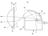
- FIG. 2 is a cross-sectional view of the lamp unit 10 along the light irradiation optical axis.
- the lamp unit 10 includes a heat sink 20, a light source 30 disposed on the heat sink 20, a reflector 40 disposed on the heat sink 20 so as to cover the light source 30 in a semi-dome shape, and a light source 30.
- the lens 50 arrange
- the heat sink 20 is a member that dissipates heat generated by the light source 30 and is preferably formed using a metal material (for example, aluminum) or a resin material having high thermal conductivity. 20 is made of aluminum die casting.
- a semiconductor type light source can be suitably used.
- an LED which is a semiconductor type light source in which a light emitting chip 32 is provided on a substrate 31 on which electric wiring for power feeding (not shown) is formed is used. ing.
- the number of light emitting chips 32 provided on the substrate 31 is not particularly limited, and may be one or plural.
- the shape of the light emitting chip 32 is not particularly limited, and may be square or rectangular. Furthermore, in this embodiment, although the example using LED is shown, you may make it use semiconductor type light sources, such as LD and EL (organic EL).
- the substrate 31 is disposed on the heat sink 20 so that the light emitting surface of the light emitting chip 32 faces upward, and the light from the light source 30 is irradiated upward. ing.
- the reflector 40 is disposed on the heat sink 20 so as to cover the light source 30 in a semi-dome shape, and the light from the light source 30 is reflected to the lens 50 side by the reflecting surface 41 of the reflector 40.
- the material used for the reflector 40 is preferably a metal material (for example, aluminum) or a resin material having a high thermal conductivity and a light-impermeable material.
- a metal material for example, aluminum
- resin material having a high thermal conductivity and a light-impermeable material for example, similar to the heat sink 20, it is made of aluminum die casting. Can be.
- the reflection surface 41 of the reflector 40 is a free-form surface based on a spheroid (ellipse) and has two focal points.
- the reflector 40 is disposed on the heat sink 20 so that the first focal point F1 of the reflecting surface 41 is located near the light emission center of the light source 30 or near the light emission center, and the second focal point F2 is located near the upper end of the shade 60. Has been.
- the lens 50 can be formed using, for example, a transparent resin material such as polycarbonate or acrylic.
- the lens 50 has a circular shape when viewed from the light irradiation direction, and as shown in FIG. 2, the incident surface 51 on which light is incident is planar, and the emission surface 52 from which light is emitted is formed.
- an aspherical lens having an arc shape protruding forward is used, for example, the surface shape of the entrance surface 51 and the exit surface 52 may be formed in another shape such as a free-form surface.
- the incident surface 51 of the lens 50 looks flat as described above when viewed from the exterior, but the incident surface 51 has a light diffusion portion (prism) formed thereon. Accordingly, the incident surface 51 is not a perfect plane because a large number of fine protrusions are formed accurately. This light diffusion part will be described in detail later.
- the lens 50 is provided with a flange 53 on the incident surface 51 side.
- the lens 53 is held by a lens holder (not shown) attached to the heat sink 20, and the rear focus of the lens 50 is the reflector 40.
- the second focal point F2 or the vicinity of the second focal point F2 is disposed.
- the shade 60 can be suitably formed using a light-impermeable material, and the upper end of the shade 60 is positioned in the vicinity of the second focus F of the reflector 40 and the rear focus of the lens 50 as shown in FIG. As shown in FIG.
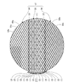
- FIG. 3 is a perspective view in which the incident surface 51 side of the lens 50 is visible.
- the state of the light diffusing portion is not shown for the incident surface 51, and only the state of the region of the incident surface 51 divided by the state of the light diffusing portion is shown.
- the lens 50 includes an upper incident surface 54 above the center of the incident surface 51 on which light is incident, an intermediate incident surface 55 including the center of the incident surface 51, and a lower side than the intermediate incident surface 55.
- a lower incident surface 56 is shown in FIG. 3, the lens 50.
- FIG. 4 is a plan view in which only the incident surface 51 is viewed from the front.
- a first light diffusion portion 54 a that diffuses light is disposed on the upper incident surface 54
- a second light diffusion portion 56 b that diffuses light is disposed on the lower incident surface 56.
- the intermediate incident surface 55 includes a third light diffusing portion 55b and a fourth light diffusing portion 55a for diffusing light
- the intermediate incident surface 55 includes a third light diffusing portion 55b and a fourth light diffusing portion.
- the intermediate incident surface 55 is third in the horizontal direction (left-right direction in the figure).
- a first arrangement pattern portion (1) in which light diffusion portions 55b and fourth light diffusion portions 55a are arranged substantially alternately; a second arrangement pattern portion (2) in which only the transparent portion 55c is arranged in the horizontal direction; And a third arrangement pattern portion (3) in which only the fourth light diffusion portion 55a is arranged in the horizontal direction.
- the intermediate incident surface 55 is positioned substantially at the center of the intermediate incident surface 55 in the vertical direction (vertical direction in the figure).
- the first arrangement pattern portion (1) (see (1) surrounded by a frame) is provided, and the second arrangement pattern portion (2) and the first arrangement pattern are sequentially arranged outward in the vertical direction (outside in the vertical direction in the figure).
- Part (1), third arrangement pattern part (3), first arrangement pattern part (1), third arrangement pattern part (3), first arrangement pattern part (1) and second arrangement pattern part (2). Is provided.
- the third arrangement pattern portion (3) is provided on the uppermost outer side (upper side in the figure) of the intermediate incident surface 55 in the vertical direction (up and down direction in the figure), and the lowermost outer side in the vertical direction of the intermediate incident surface 55 ( A first arrangement pattern portion (1) is provided on the lower side of the drawing.
- the third light diffusing portion 55b is provided so as to be distributed almost uniformly
- the fourth light diffusion portion 55a is provided so as not to be biased as a whole
- the through portion 55c is provided so as not to be biased as a whole.
- the lens 50 is attached due to an attachment error during assembly. Even if the position is slightly shifted, the light diffusion state does not change. For this reason, the intermediate incident surface 55 can obtain a stable light diffusion state.
- the upper incident surface 54 has the first light diffusing portion 54a arranged uniformly on the entire surface
- the lower incident surface 56 has the second light diffusing portion 56b arranged uniformly on the entire surface.
- the intermediate incident surface 55 the upper incident surface 54 and the lower incident surface 56 do not change the light diffusion state even if the mounting position of the lens 50 is slightly shifted due to mounting errors during assembly. For this reason, both the upper incident surface 54 and the lower incident surface 56 can obtain a stable light diffusion state, like the intermediate incident surface 55.
- the first light diffusing unit 54a, the second light diffusing unit 56b, the third light diffusing unit 55b, and the fourth light diffusing unit 55a are all of the same shape.
- the first light diffusing unit 54a, the second light diffusing unit 56b, the third light diffusing unit 55b, and the fourth light diffusing unit 55a are all rhombus-shaped in the direction away from the incident surface 51 (light source 30).
- the prism is a rhombus quadrangular pyramid that protrudes toward the side.
- the fourth light diffusion portion 55a has a rhombus quadrangular pyramid height (projection amount) of 10 ⁇ m, and similarly, the first light diffusion portion 54a has a rhombus quadrangular pyramid height (protrusion amount) of 10 ⁇ m. Yes.
- the first light diffusion portion 54a has the light diffusion width of the fourth light diffusion portion 55a. It is almost the same as the width.
- the third light diffusing portion 55b has a rhombus quadrangular pyramid height (projection amount) of 20 ⁇ m.
- the second light diffusing portion 56b has a rhombus quadrangular pyramid height (protrusion amount) of 20 ⁇ m. Yes. Accordingly, the light diffusion width of the third light diffusion portion 55b is substantially the same as the light diffusion width of the second light diffusion portion 56b.
- the intermediate incident surface 55 is provided with the through portion 55c where the light diffusion portions (the third light diffusion portion 55b and the fourth light diffusion portion 55a) are not disposed. Incident light enters the lens 50 without being diffused.
- the amount of light distribution pattern formed by the light incident on the intermediate incident surface 55 is small.
- the light incident from the portion where the light diffusing portion (the third light diffusing portion 55b and the fourth light diffusing portion 55a) is arranged is diffused by an amount corresponding to the diffusion width of the light diffusing portion, and the inside of the lens 50 is diffused. Is incident on. That is, when light is incident on the lens 50, light incident from a portion of the third light diffusion portion 55b having a large light diffusion width enters the lens 50 with a large diffusion width, and the light diffusion width is small. Light incident from a portion of the small fourth light diffusion portion 55a enters the lens 50 with a small diffusion width.
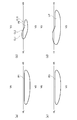
- FIG. 5 is a diagram showing a light distribution pattern on the screen
- FIG. 5 (a) is a diagram showing a light distribution pattern P1 by light incident on the upper incident surface 54
- FIG. 5 (b) is an intermediate incidence
- FIG. 5C is a diagram showing a light distribution pattern P3 by light incident on the lower incident surface 56
- FIG. 5D is a diagram showing a light distribution pattern P2 by light incident on the surface 55.
- FIG. It is a figure which shows the low beam light distribution pattern LP with which the light patterns P1, P2, and P3 were multiplexed.
- the light incident on the upper incident surface 54 (see FIG. 5A) and the lower incident surface 56 (see FIG. 5C) is a diffused light distribution pattern of a low beam light distribution pattern.
- the light incident on the intermediate incident surface 55 (see FIG. 5B) is a condensed light distribution of a low beam light distribution pattern including the upper cutoff line CL1, the oblique cutoff line CL2, and the lower cutoff line CL3.
- a pattern is formed.
- the upper cut-off line CL1, the oblique cut-off line CL2, and the lower cut-off line CL3 may be collectively referred to as a cut-off line CL in some cases.
- the intermediate incident surface 55 has the through portion 55c, and the light incident on the lens 50 from the through portion 55c is not diffused, so the amount of light distribution pattern is reduced.
- the cut-off line CL can be easily viewed.
- FIG. 6 is an enlarged view of a part of the cut-off line CL of the light distribution pattern on the screen formed by the light incident on the intermediate incident surface 55.
- FIG. 6 (a) is for comparison.
- FIG. 6 is a view showing a case where the same light diffusion portion as the third light diffusion portion 55b is arranged on the entire surface of the intermediate incident surface 55 without a gap
- FIG. 6B is a view showing the case of this embodiment. .
- the light diffusion portion is formed on the intermediate incident surface 55, the upper cutoff line CL1, the oblique cutoff line CL2, and the lower cutoff line CL3.
- the light diffused by the light diffusion portion is irradiated on the upper side, and the light distribution spreads to the range indicated by the alternate long and short dash line SL.
- the sudden darkening at the cut-off line CL is alleviated, and the visibility is good for the driver.
- the through portion 55c is provided in the intermediate incident surface 55 as in the present embodiment, the amount of light distribution pattern is reduced accordingly, and the amount of cut-off CL is reduced accordingly.
- the cut-off line CL becomes clearer than in the case of FIG.
- the cut-off line CL becomes easy to visually recognize, workability at the time of adjustment by aiming or the like can be improved.
- the third light diffusion portion 55b having a large light diffusion width and the light diffusion width are Small fourth light diffusion portions 55a are mixed.
- the light diffused by the fourth light diffusing portion 55a having a small light diffusion width is applied to the position indicated by the dotted line SLM between the cut-off line CL and the position indicated by the alternate long and short dash line SL.
- the light quantity gradually decreases from the cut-off line CL toward the one-dot chain line SL.
- the upper incident surface 54, the intermediate incident surface 55, and the lower incident surface 56 shown in FIG. 3 each have a maximum width in the vertical direction (the vertical direction in the figure), and the vertical direction of the incident surface 51.
- the intermediate incident surface 55 has a width (maximum width) in the vertical direction (up and down direction) of the intermediate incident surface 55 that is 20% or more and 45% or less of the maximum width in the vertical direction of the incident surface 51.
- the intermediate incident surface 55 is set so that a substantially middle (center) portion of the width in the vertical direction is located at the center of the incident surface 51.
- the light diffusing unit (the first light diffusing unit 54a, the second light diffusing unit 56b, the third light diffusing unit 55b, and the fourth light diffusing unit 55a)
- the prism is not necessarily limited to a rhombus, and may be formed as a prism such as a regular quadrangular pyramid whose bottom is a regular square. May be changed.
- the height (projection amount) of the light diffusing sections is also the height specifically shown above. There is no need to be limited. As described above, the height (protrusion amount) of the light diffusion portion (the first light diffusion portion 54a, the second light diffusion portion 56b, the third light diffusion portion 55b, and the fourth light diffusion portion 55a) is increased (the protrusion amount is reduced). If the height is larger, the light diffusion width becomes larger, and conversely, if the height (projection amount) is lowered (projection amount is smaller), the light diffusion width becomes smaller. The height (projection amount) of the light diffusing part (the first light diffusing part 54a, the second light diffusing part 56b, the third light diffusing part 55b, and the fourth light diffusing part 55a) is adjusted so as to be suitable for Also good.
- the height (projection amount) of the first light diffusion portion 54a is preferably 10 ⁇ m or less.
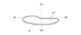
- FIG. 7 is a diagram showing the low beam light distribution pattern LP of FIG. 5D, that is, a diagram showing the light distribution pattern of the vehicular lamp of the embodiment.
- the light incident from the lower side of the lower incident surface 56 where the light passing through the lower side of the lens 50 is incident forms the lower side of the low beam light distribution pattern LP.
- the second light diffusing portion 56b is provided uniformly on almost the entire lower incident surface 56, the light irradiated below the low beam light distribution pattern LP is also diffused. It has become.
- the lower side of the low-beam light distribution pattern LP is a light distribution portion that illuminates the immediate vicinity of the vehicle 102. Therefore, if the irradiated light group has light intensity unevenness, the state of light intensity unevenness is likely to appear. In some cases, light intensity unevenness due to light diffusion by the second light diffusing unit 56b may appear below the low beam light distribution pattern LP like the region A surrounded by the dotted line shown in FIG. Therefore, in order to suppress such light intensity unevenness, it is preferable not to arrange the second light diffusion portion 56 b in the lower portion of the lower incident surface 56.
- FIG. 8 is a view showing a modified example of the incident surface 51 of the lens 50, and more specifically, a diagram showing a case where the second light diffusion portion 56b is not disposed in the lower portion of the lower incident surface 56.
- FIG. 8 on the lower incident surface 56, when the widest width in the vertical direction (the vertical direction in the figure) is the lower incident surface width, ) So that the second light diffusing portion 56b is arranged without a gap in a region that is substantially half of the width of the lower incident surface, and the remaining region of the lower incident surface 56 is formed by the second light diffusing portion 56b.
- the threading portion 56c is not arranged.
- the present invention has been described based on the specific embodiments, the present invention is not limited to the above embodiments.
- the vehicle lamp for left-side traveling has been illustrated and described.
- the light diffusing portion provided on the entrance surface of the lens is configured as described above, the same applies. Therefore, the present invention is not limited to the vehicular lamp for driving on the left side.
Landscapes
- Engineering & Computer Science (AREA)
- General Engineering & Computer Science (AREA)
- Physics & Mathematics (AREA)
- Optics & Photonics (AREA)
- Microelectronics & Electronic Packaging (AREA)
- Non-Portable Lighting Devices Or Systems Thereof (AREA)
Abstract
エイミング等による調整の際の作業性を考慮した上で、路面上の配光ムラの発生を抑制した車両用灯具を提供するため、本発明の車両用灯具は、光源(30)と光源(30)の前方側に配置されるレンズ(50)とを備えるカットオフラインCLを有する配光を形成する車両用灯具であって、光源(30)からの光が入射するレンズ(50)の入射面(51)は、光を拡散する第1光拡散部(54a)が配置され、入射面(51)の中央より上側の上側入射面(54)と、光を拡散する第2光拡散部(56)が配置され、入射面(51)の中央より下側の下側入射面(56)と、光を拡散する第3光拡散部(55b)及び第4光拡散部(55a)が配置されるとともに第3光拡散部(55b)及び第4光拡散部(55a)の配置されない素通し部(55c)を有する前記入射面の中央を含む中間入射面(55)と、を備え、第3光拡散部(55b)は、光の拡散幅が第4光拡散部(55a)の光の拡散幅よりも大きい。
Description
本発明は車両用灯具に関するものである。
半導体発光素子からの光が、投影レンズの入射面に入射する際に、上下方向拡散部により上下方向に拡散させ、配光パターンのカットオフラインを上下方向に拡散させて暈すことでドライバーの視認性を向上した車両用灯具では、路面に光のスジ(光のスジ斑)が発生する場合があった。
そこで、この問題を解決するために、特許文献1には、光源と、光源からの光をカットオフラインを有する配光パターンとして外部に照射するレンズと、を備え、レンズの入射面には、入射光を拡散させる拡散部が設けられていて、拡散部が、連続する微小凹曲面もしくは微小凸曲面を交差させて設けてなる車両用灯具が開示されている(特許文献1参照)。
この特許文献1に開示された車両用灯具では、レンズの入射面の全面(配光パターンを形成するのに寄与する範囲となる全ての面)に隙間なく密に拡散部が設けられている。
特許文献1のように、カットオフラインを暈すようにすることで、カットオフラインを境として上側の領域が急激に暗くなることが抑制できるのでドライバーにとっての視認性を良くすることができるものの、カットオフラインも視認し難くなり、エイミング等による車両用灯具の調整の際の作業性が低下する。
本発明は、このような事情に鑑みてなされたものであり、エイミング等による調整の際の作業性を考慮した上で、路面上の配光ムラの発生を抑制した車両用灯具を提供することを目的とする。
本発明は、上記目的を達成するために以下の構成によって把握される。
(1)本発明の車両用灯具は、光源と前記光源の前方側に配置されるレンズとを備えるカットオフラインを有する配光を形成する車両用灯具であって、前記光源からの光が入射する前記レンズの入射面は、前記光を拡散する第1光拡散部が配置され、前記入射面の中央より上側の上側入射面と、前記光を拡散する第2光拡散部が配置され、前記入射面の中央より下側の下側入射面と、前記光を拡散する第3光拡散部及び第4光拡散部が配置されるとともに前記第3光拡散部及び前記第4光拡散部の配置されない素通し部を有する前記入射面の中央を含む中間入射面と、を備え、前記第3光拡散部は、前記光の拡散幅が前記第4光拡散部の前記光の拡散幅よりも大きい。
(1)本発明の車両用灯具は、光源と前記光源の前方側に配置されるレンズとを備えるカットオフラインを有する配光を形成する車両用灯具であって、前記光源からの光が入射する前記レンズの入射面は、前記光を拡散する第1光拡散部が配置され、前記入射面の中央より上側の上側入射面と、前記光を拡散する第2光拡散部が配置され、前記入射面の中央より下側の下側入射面と、前記光を拡散する第3光拡散部及び第4光拡散部が配置されるとともに前記第3光拡散部及び前記第4光拡散部の配置されない素通し部を有する前記入射面の中央を含む中間入射面と、を備え、前記第3光拡散部は、前記光の拡散幅が前記第4光拡散部の前記光の拡散幅よりも大きい。
(2)上記(1)の構成において、前記第1光拡散部は、前記光の拡散幅が前記第4光拡散部の前記光の拡散幅とほぼ同じである。
(3)上記(1)又は(2)の構成において、前記第3光拡散部は、前記光の拡散幅が前記第2光拡散部の前記光の拡散幅とほぼ同じである。
(4)上記(1)から(3)のいずれか1つの構成において、前記中間入射面は、水平方向に前記第3光拡散部と前記第4光拡散部がほぼ交互に配置された第1配置パターン部と、水平方向にほぼ前記素通し部だけが配置された第2配置パターン部と、水平方向にほぼ前記第4光拡散部だけが配置された第3配置パターン部と、を備え、前記中間入射面には、前記中間入射面の鉛直方向のほぼ中央に位置するように前記第1配置パターン部が設けられるとともに、鉛直方向外側に向かって、順次、第2配置パターン部、第1配置パターン部、第3配置パターン部、第1配置パターン部、第3配置パターン部、第1配置パターン部及び第2配置パターン部が設けられ、さらに、前記中間入射面の鉛直方向の最も上外側に第3配置パターン部が設けられるとともに、前記中間入射面の鉛直方向の最も下外側に第1配置パターン部が設けられている。
(5)上記(1)から(4)のいずれか1つの構成において、前記上側入射面には、ほぼ全体に隙間なく前記第1光拡散部が配置されている。
(6)上記(1)から(5)のいずれか1つの構成において、前記下側入射面には、鉛直方向の最も広い幅を下側入射面幅としたときに、前記中間入射面から鉛直方向下側に向かって、ほぼ下側入射面幅の半分となる領域に隙間なく前記第2光拡散部が配置されており、前記下側入射面の残る領域は、前記第2光拡散部が配置されない素通し部とされている。
(7)上記(1)から(5)のいずれか1つの構成において、前記下側入射面には、ほぼ全体に隙間なく前記第2光拡散部が配置されている。
(8)上記(1)から(7)のいずれか1つの構成において、前記中間入射面は、前記入射面の中央が前記中間入射面の鉛直方向の幅のほぼ中間に位置するように形成されており、前記中間入射面の鉛直方向の幅が、前記入射面全体の鉛直方向の最大幅の20%以上45%以下の幅とされている。
(9)上記(1)から(8)のいずれか1つの構成において、前記光源を半ドーム状に覆うように設けられ、前記光源からの光を前記レンズ側に反射するリフレクタと、前記リフレクタと前記レンズとの間に配置され、前記リフレクタで反射された光の一部を遮光するシェードと、を備える。
本発明によれば、エイミング等による調整の際の作業性を考慮した上で、路面上の配光ムラの発生を抑制した車両用灯具を提供することができる。
以下、添付図面を参照して、本発明を実施するための形態(以下、「実施形態」と称する)について詳細に説明する。実施形態の説明の全体を通して同じ要素には同じ番号を付している。また、実施形態及び図中において、特に断りがない場合、「前」、「後」は、各々、車両の「前進方向」、「後進方向」を示し、「上」、「下」、「左」、「右」は、各々、車両に乗車する運転者から見た方向を示す。
本発明の実施形態に係る車両用灯具は、図1に示す車両102の前方の左右の自動車用前照灯(101R、101L)のそれぞれに搭載される車両用灯具であり、以下では、左側走行用の車両用灯具について説明する。
本実施形態の車両用灯具は、車両前方側に開口したハウジング(図示せず)と開口を覆うようにハウジングに取付けられるアウターレンズ(図示せず)を備え、ハウジングとアウターレンズとで形成される灯室内に灯具ユニット10(図2参照)等が配置されている。
図2は、灯具ユニット10の光照射光軸に沿った断面図である。
図2に示すように、灯具ユニット10は、ヒートシンク20と、ヒートシンク20上に配置される光源30と、光源30を半ドーム状に覆うようにヒートシンク20上に配置されるリフレクタ40と、光源30の前方側に配置されるレンズ50と、リフレクタ40とレンズ50との間に配置されるシェード60と、を備える。
図2に示すように、灯具ユニット10は、ヒートシンク20と、ヒートシンク20上に配置される光源30と、光源30を半ドーム状に覆うようにヒートシンク20上に配置されるリフレクタ40と、光源30の前方側に配置されるレンズ50と、リフレクタ40とレンズ50との間に配置されるシェード60と、を備える。
(ヒートシンク)
ヒートシンク20は、光源30が発生する熱を放熱する部材であり、熱伝導率の高い金属材料(例えば、アルミ等)や樹脂材料を用いて成形されるのが好適であり、本実施形態のヒートシンク20はアルミダイカスト製のものとしている。
ヒートシンク20は、光源30が発生する熱を放熱する部材であり、熱伝導率の高い金属材料(例えば、アルミ等)や樹脂材料を用いて成形されるのが好適であり、本実施形態のヒートシンク20はアルミダイカスト製のものとしている。
(光源)
光源30は、半導体型光源を好適に用いることができ、本実施形態では、図示しない給電用の電気配線等が形成された基板31上に発光チップ32を設けた半導体型光源であるLEDを用いている。
基板31上に設ける発光チップ32の数は特に限定されるものではなく、1つでも、複数でも良い。
光源30は、半導体型光源を好適に用いることができ、本実施形態では、図示しない給電用の電気配線等が形成された基板31上に発光チップ32を設けた半導体型光源であるLEDを用いている。
基板31上に設ける発光チップ32の数は特に限定されるものではなく、1つでも、複数でも良い。
また、発光チップ32の形状も特に限定されるものではなく、正方形状でも、長方形状でも良い。
さらに、本実施形態では、LEDを用いた例を示しているが、LDやEL(有機EL)といった半導体型光源を用いるようにしても良い。
さらに、本実施形態では、LEDを用いた例を示しているが、LDやEL(有機EL)といった半導体型光源を用いるようにしても良い。
図2に示すように、本実施形態では、ヒートシンク20上に発光チップ32の発光面が上側を向くように基板31が配置され、光源30からの光は、上方側に照射されるようになっている。
(リフレクタ)
リフレクタ40は、光源30を半ドーム状に覆うようにヒートシンク20上に配置され、光源30からの光は、リフレクタ40の反射面41によってレンズ50側に反射される。
リフレクタ40に用いる材料は、熱伝導率が高い金属材料(例えば、アルミ等)や樹脂材料で、且つ、光不透過性の材料とすることが好ましく、例えば、ヒートシンク20と同様に、アルミダイカスト製のものとすることができる。
リフレクタ40は、光源30を半ドーム状に覆うようにヒートシンク20上に配置され、光源30からの光は、リフレクタ40の反射面41によってレンズ50側に反射される。
リフレクタ40に用いる材料は、熱伝導率が高い金属材料(例えば、アルミ等)や樹脂材料で、且つ、光不透過性の材料とすることが好ましく、例えば、ヒートシンク20と同様に、アルミダイカスト製のものとすることができる。
リフレクタ40の反射面41は、回転楕円面(楕円)を基本とした自由曲面からなり、2つの焦点を有している。
そして、リフレクタ40は、反射面41の第1焦点F1が光源30の発光中心若しくは発光中心の近傍に位置するとともに、第2焦点F2がシェード60の上端近傍に位置するようにヒートシンク20上に配置されている。
そして、リフレクタ40は、反射面41の第1焦点F1が光源30の発光中心若しくは発光中心の近傍に位置するとともに、第2焦点F2がシェード60の上端近傍に位置するようにヒートシンク20上に配置されている。
(レンズ)
レンズ50は、例えば、ポリカーボネートやアクリル等の透明樹脂材料を用いて形成することができる。
本実施形態では、レンズ50は、光照射方向から見た正面視が円形状であり、図2に示すように、光が入射する入射面51が平面状で、光が出射する出射面52が前方側に突出する円弧状である非球面レンズを用いているが、例えば、入射面51や出射面52の面形状を自由曲面等の他の形状で形成するようにしても良い。
レンズ50は、例えば、ポリカーボネートやアクリル等の透明樹脂材料を用いて形成することができる。
本実施形態では、レンズ50は、光照射方向から見た正面視が円形状であり、図2に示すように、光が入射する入射面51が平面状で、光が出射する出射面52が前方側に突出する円弧状である非球面レンズを用いているが、例えば、入射面51や出射面52の面形状を自由曲面等の他の形状で形成するようにしても良い。
なお、本実施形態のレンズ50の入射面51は、外観として見たときに上述のように平面状に見えるが、入射面51には光拡散部(プリズム)が形成されている。
したがって、入射面51は、正確には多数の微細な突条が形成されているので完全な平面ではない。この光拡散部に関しては後ほど詳細に説明する。
したがって、入射面51は、正確には多数の微細な突条が形成されているので完全な平面ではない。この光拡散部に関しては後ほど詳細に説明する。
また、レンズ50は、入射面51側にフランジ53が設けられており、例えば、ヒートシンク20に取付けられる図示しないレンズホルダによってフランジ53が把持されて、レンズ50は、レンズ50の後方焦点がリフレクタ40の第2焦点F2若しくは第2焦点F2近傍に位置するように配置されている。
(シェード)
シェード60は、光不透過性の材料を用いて好適に形成することができ、図2に示すように、シェード60の上端がリフレクタ40の第2焦点F及びレンズ50の後方焦点近傍に位置するようにヒートシンク20に取付けられている。
シェード60は、光不透過性の材料を用いて好適に形成することができ、図2に示すように、シェード60の上端がリフレクタ40の第2焦点F及びレンズ50の後方焦点近傍に位置するようにヒートシンク20に取付けられている。
そして、リフレクタ40の反射面41で反射され、レンズ50側に向かう光のうちの一部の光を遮光してロービーム配光パターンLPのカットオフラインCLを形成する。
次に、図3を参照しながらレンズ50の入射面51に形成される光拡散部について説明する。
図3は、レンズ50の入射面51側が見えるようにした斜視図である。
なお、図3では、入射面51について、光拡散部の状態の図示を省略し、その光拡散部の状態によって区分される入射面51の領域の状態だけを示している。
図3は、レンズ50の入射面51側が見えるようにした斜視図である。
なお、図3では、入射面51について、光拡散部の状態の図示を省略し、その光拡散部の状態によって区分される入射面51の領域の状態だけを示している。
図3に示すように、レンズ50は、光の入射する入射面51の中央より上側の上側入射面54と、入射面51の中央を含む中間入射面55と、中間入射面55よりも下側の下側入射面56と、を備えている。
図4は、入射面51だけを正面に見るようにした平面図である。
図4に示すように、上側入射面54には、光を拡散する第1光拡散部54aが配置され、下側入射面56には、光を拡散する第2光拡散部56bが配置されている。
また、中間入射面55には、光を拡散する第3光拡散部55b及び第4光拡散部55aが配置されるとともに、中間入射面55は、第3光拡散部55b及び第4光拡散部55aの配置されない素通し部55cを有している。
図4に示すように、上側入射面54には、光を拡散する第1光拡散部54aが配置され、下側入射面56には、光を拡散する第2光拡散部56bが配置されている。
また、中間入射面55には、光を拡散する第3光拡散部55b及び第4光拡散部55aが配置されるとともに、中間入射面55は、第3光拡散部55b及び第4光拡散部55aの配置されない素通し部55cを有している。
より詳細に中間入射面55について見てみると、図4の右側に(1)、(2)及び(3)で示すように、中間入射面55は、水平方向(図左右方向)に第3光拡散部55bと第4光拡散部55aがほぼ交互に配置された第1配置パターン部(1)と、水平方向にほぼ素通し部55cだけが配置された第2配置パターン部(2)と、水平方向にほぼ第4光拡散部55aだけが配置された第3配置パターン部(3)と、を備えている。
そして、図4の左側に(1)、(2)及び(3)で示すように、中間入射面55には、中間入射面55の鉛直方向(図上下方向)のほぼ中央に位置するように第1配置パターン部(1)(枠囲みした(1)参照)が設けられるとともに、鉛直方向外側(図上下方向外側)に向かって、順次、第2配置パターン部(2)、第1配置パターン部(1)、第3配置パターン部(3)、第1配置パターン部(1)、第3配置パターン部(3)、第1配置パターン部(1)及び第2配置パターン部(2)が設けられている。
そして、さらに、中間入射面55の鉛直方向(図上下方向)の最も上外側(図上側)に第3配置パターン部(3)が設けられるとともに、中間入射面55の鉛直方向の最も下外側(図下側)に第1配置パターン部(1)が設けられている。
このように第3光拡散部55b、第4光拡散部55a及び素通し部55cが配置された中間入射面55では、ほぼ均一に分散配置されるように第3光拡散部55bが設けられるとともに、全体的に見て偏りがないように第4光拡散部55aが設けられ、同様に、全体的に見て偏りがないように素通し部55cが設けられている。
したがって、中間入射面55には、偏りがないように、第3光拡散部55b、第4光拡散部55a及び素通し部55cが配置されているので、組立時の取付け誤差等によってレンズ50の取付け位置が少しズレたとしても光の拡散状態が変化しない。
このため、中間入射面55は、安定した光の拡散状態を得ることができるものになっている。
このため、中間入射面55は、安定した光の拡散状態を得ることができるものになっている。
なお、上記では、詳細に第3光拡散部55b、第4光拡散部55a及び素通し部55cの配置状態を説明したが、これは、良好な配置の一例であって、必ずしも、このような詳細な配置になっていなくても良く、第3光拡散部55b、第4光拡散部55a及び素通し部55cが、中間入射面55において極端な偏りがないように配置されていれば、同様に、中間入射面55は安定した光の拡散状態を得ることができるものになる
また、上側入射面54は、ほぼ全面に均一に第1光拡散部54aが配置されており、下側入射面56にも、ほぼ全面に均一に第2光拡散部56bが配置されているので、中間入射面55と同様に、上側入射面54及び下側入射面56も、組立時の取付誤差等によってレンズ50の取付け位置が少しズレたとしても光の拡散状態が変化しない。
このため、上側入射面54及び下側入射面56は、どちらも中間入射面55と同様に、安定した光の拡散状態を得ることができるものになっている。
このため、上側入射面54及び下側入射面56は、どちらも中間入射面55と同様に、安定した光の拡散状態を得ることができるものになっている。
本実施形態では、第1光拡散部54a、第2光拡散部56b、第3光拡散部55b及び第4光拡散部55aは、いずれも同じ形状のものとしている。
具体的には、第1光拡散部54a、第2光拡散部56b、第3光拡散部55b及び第4光拡散部55aは、いずれも底面がひし形形状で入射面51から離れる方向(光源30側)に向かって突出するひし形四角錐としたプリズムとしている。
具体的には、第1光拡散部54a、第2光拡散部56b、第3光拡散部55b及び第4光拡散部55aは、いずれも底面がひし形形状で入射面51から離れる方向(光源30側)に向かって突出するひし形四角錐としたプリズムとしている。
そして、第4光拡散部55aは、ひし形四角錐の高さ(突出量)が10μmであり、同様に、第1光拡散部54aもひし形四角錐の高さ(突出量)が10μmになっている。
ここで、光が拡散するときの拡散幅は、ひし形四角錐の高さ(突出量)によって変わるため、第1光拡散部54aは、光の拡散幅が第4光拡散部55aの光の拡散幅とほぼ同じであるようになっている。
また、第3光拡散部55bは、ひし形四角錐の高さ(突出量)が20μmであり、同様に、第2光拡散部56bもひし形四角錐の高さ(突出量)が20μmになっている。
したがって、第3光拡散部55bは、光の拡散幅が第2光拡散部56bの光の拡散幅とほぼ同じであるようになっている。
したがって、第3光拡散部55bは、光の拡散幅が第2光拡散部56bの光の拡散幅とほぼ同じであるようになっている。
上述したように、中間入射面55には、光拡散部(第3光拡散部55b及び第4光拡散部55a)の配置されていない素通し部55cが設けられているので、この素通し部55cから入射する光は拡散されることなくレンズ50内に入射する。
このため、中間入射面55の全面に隙間なく光拡散部を設ける場合に比べ、中間入射面55に入射する光によって形成される配光パターンの部分の暈し量が少ないものになる。
一方、光拡散部(第3光拡散部55b及び第4光拡散部55a)の配置されている部分から入射する光は、その光拡散部の拡散幅に応じた分だけ拡散されてレンズ50内に入射する。
つまり、レンズ50に光が入射するときに、光の拡散幅が大きい第3光拡散部55bのある部分から入射する光は、拡散幅が大きい状態でレンズ50に入射し、光の拡散幅が小さい第4光拡散部55aのある部分から入射する光は、拡散幅が小さい状態でレンズ50に入射する。
つまり、レンズ50に光が入射するときに、光の拡散幅が大きい第3光拡散部55bのある部分から入射する光は、拡散幅が大きい状態でレンズ50に入射し、光の拡散幅が小さい第4光拡散部55aのある部分から入射する光は、拡散幅が小さい状態でレンズ50に入射する。
次に、このような構成からなる車両用灯具の配光パターンについて以下説明する。
図5は、スクリーン上での配光パターンを示す図であり、図5(a)は上側入射面54に入射した光による配光パターンP1を示す図であり、図5(b)は中間入射面55に入射した光による配光パターンP2を示す図であり、図5(c)は下側入射面56に入射した光による配光パターンP3を示す図であり、図5(d)は配光パターンP1、P2及びP3が多重されたロービーム配光パターンLPを示す図である。
図5は、スクリーン上での配光パターンを示す図であり、図5(a)は上側入射面54に入射した光による配光パターンP1を示す図であり、図5(b)は中間入射面55に入射した光による配光パターンP2を示す図であり、図5(c)は下側入射面56に入射した光による配光パターンP3を示す図であり、図5(d)は配光パターンP1、P2及びP3が多重されたロービーム配光パターンLPを示す図である。
図5を見るとわかるように、上側入射面54(図5(a)参照)及び下側入射面56(図5(c)参照)に入射した光は、ロービーム配光パターンの拡散配光パターンを形成しており、中間入射面55(図5(b)参照)に入射した光は、上側カットオフラインCL1、斜めカットオフラインCL2、下側カットオフラインCL3を含むロービーム配光パターンの集光配光パターンを形成している。
なお、以下では、上側カットオフラインCL1、斜めカットオフラインCL2、下側カットオフラインCL3をまとめて単にカットオフラインCLと記載する場合がある。
なお、以下では、上側カットオフラインCL1、斜めカットオフラインCL2、下側カットオフラインCL3をまとめて単にカットオフラインCLと記載する場合がある。
そして、上述したように、中間入射面55は、素通し部55cを有しており、この素通し部55cの部分からレンズ50に入射する光は拡散されないので、配光パターンの暈し量を少なくすることができ、以下、図6を参照して説明するようにカットオフラインCLを視認しやすくできる。
図6は、中間入射面55に入射した光によって形成されるスクリーン上での配光パターンのカットオフラインCLの一部を拡大して示した図であり、図6(a)は比較のための図であり、中間入射面55の全面に隙間なく第3光拡散部55bと同じ光拡散部を配置した場合を示す図であり、図6(b)は本実施形態の場合を示す図である。
図6(a)及び図6(b)のどちらの場合も、中間入射面55に光拡散部が形成されているので、上側カットオフラインCL1、斜めカットオフラインCL2、及び、下側カットオフラインCL3の上側に光拡散部で拡散された光が照射され、一点鎖線SLで示す範囲まで配光が広がっている。
このため、カットオフラインCLを境として急激に暗くなるのが緩和され、ドライバーにとって視認性の良い状態となっている。
しかしながら、本実施形態のように、中間入射面55に素通し部55cを設けるようにすると、その分だけ配光パターンの暈し量が少なくなるため、カットオフラインCLの暈し量も少なくなり、図6(b)に示すように、図6(a)の場合よりも、カットオフラインCLが明瞭なものとなる。
しかしながら、本実施形態のように、中間入射面55に素通し部55cを設けるようにすると、その分だけ配光パターンの暈し量が少なくなるため、カットオフラインCLの暈し量も少なくなり、図6(b)に示すように、図6(a)の場合よりも、カットオフラインCLが明瞭なものとなる。
このため、カットオフラインCLが視認しやすくなるため、エイミング等による調整の際の作業性を良くすることができる。
しかも、上述したように、本実施形態では、単に素通し部55cを配置するようにしただけでなく、光拡散部においても、光の拡散幅が大きい第3光拡散部55bと光の拡散幅が小さい第4光拡散部55aを混在させるようにしている。
このため、この光の拡散幅が小さい第4光拡散部55aで拡散された光が、カットオフラインCLと一点鎖線SLで示す位置との間の点線SLMで示す位置に照射されることになるため、カットオフラインCLから一点鎖線SLに向かって光量が緩やかに減少するような良好な状態になっている。
しかも、上述したように、本実施形態では、単に素通し部55cを配置するようにしただけでなく、光拡散部においても、光の拡散幅が大きい第3光拡散部55bと光の拡散幅が小さい第4光拡散部55aを混在させるようにしている。
このため、この光の拡散幅が小さい第4光拡散部55aで拡散された光が、カットオフラインCLと一点鎖線SLで示す位置との間の点線SLMで示す位置に照射されることになるため、カットオフラインCLから一点鎖線SLに向かって光量が緩やかに減少するような良好な状態になっている。
なお、本実施形態では、図3に示した上側入射面54、中間入射面55、及び、下側入射面56は、鉛直方向(図上下方向)での最大幅をそれぞれ入射面51の鉛直方向の最大幅に対して1/3ずつの幅となるようにしているが、必ずしも、このように均等幅とする必要はなく、中間入射面55は、カットオフラインCLを主に形成する光が入射する入射面51の部分をカバーする幅を有するようにされていれば良い。
このことから、中間入射面55は、中間入射面55の鉛直方向(図上下方向)の幅(最大幅)が入射面51の鉛直方向の最大幅の20%以上45%以下の幅を有するようにして、中間入射面55の鉛直方向の幅のほぼ中間(中央)の部分が入射面51の中央に位置するように設定するのが好適である。
また、上記実施形態では、光拡散部(第1光拡散部54a、第2光拡散部56b、第3光拡散部55b及び第4光拡散部55a)が、底面をひし形としたひし形四角錐からなるプリズムとして形成されていたが、必ずしも底面をひし形とすることに限定されるものではなく、底面が正四角形である正四角錐のようなプリズムとして形成されていても良く、必要に応じてその形状を変更しても良い。
光拡散部(第1光拡散部54a、第2光拡散部56b、第3光拡散部55b及び第4光拡散部55a)の高さ(突出量)も上記で具体的に示した高さに限定される必要はない。
上述したように、光拡散部(第1光拡散部54a、第2光拡散部56b、第3光拡散部55b及び第4光拡散部55a)の高さ(突出量)を高く(突出量を大きく)すれば、光の拡散幅が大きくなり、逆に、高さ(突出量)を低く(突出量を小さく)すれば、光の拡散幅が小さくなるので、求められる配光の暈し具合に適するように、光拡散部(第1光拡散部54a、第2光拡散部56b、第3光拡散部55b及び第4光拡散部55a)の高さ(突出量)を調節するようにしても良い。
上述したように、光拡散部(第1光拡散部54a、第2光拡散部56b、第3光拡散部55b及び第4光拡散部55a)の高さ(突出量)を高く(突出量を大きく)すれば、光の拡散幅が大きくなり、逆に、高さ(突出量)を低く(突出量を小さく)すれば、光の拡散幅が小さくなるので、求められる配光の暈し具合に適するように、光拡散部(第1光拡散部54a、第2光拡散部56b、第3光拡散部55b及び第4光拡散部55a)の高さ(突出量)を調節するようにしても良い。
ただし、上側入射面54には、光源30からの直射光も入射し、この直射光を光の拡散幅の大きい光拡散部で拡散すると路面に光の拡散に伴う陰影(プリズムの陰影)が映る場合があるので、第1光拡散部54aの高さ(突出量)は10μm以下であることが好ましい。
(変形例)
図7は、図5(d)のロービーム配光パターンLPを示した図、つまり、上記実施形態の車両用灯具の配光パターンを示した図である。
図7は、図5(d)のロービーム配光パターンLPを示した図、つまり、上記実施形態の車両用灯具の配光パターンを示した図である。
ここで、図2に示す光線L1を見るとわかるように、レンズ50の下側を通過する光は、下側に配光されていることから、ロービーム配光パターンLPの下側に照射される光になっている。
そして、このことは、レンズ50の下側を通過する光が入射する下側入射面56の下側から入射した光が、ロービーム配光パターンLPの下側を形成するものになっていることを意味する。
上記実施形態では、下側入射面56のほぼ全面に均一に第2光拡散部56bを設けるようにしていたので、このロービーム配光パターンLPの下側に照射される光についても拡散されるようになっている。
上記実施形態では、下側入射面56のほぼ全面に均一に第2光拡散部56bを設けるようにしていたので、このロービーム配光パターンLPの下側に照射される光についても拡散されるようになっている。
このロービーム配光パターンLPの下側は、車両102の直近を照らす配光部分となるため、照射される光線群が光度ムラを有していると、その光度ムラの状態が現れやすく、このため、図7に示す点線で囲む領域Aのようなロービーム配光パターンLPの下側に、この第2光拡散部56bによる光の拡散に伴う光度ムラが現れる場合がある。
そこで、このような光度ムラを抑制するために、下側入射面56の下側部分に第2光拡散部56bを配置しないようにするのが好ましい。
そこで、このような光度ムラを抑制するために、下側入射面56の下側部分に第2光拡散部56bを配置しないようにするのが好ましい。
図8は、レンズ50の入射面51の変形例を示す図であり、具体的には、下側入射面56の下側部分に第2光拡散部56bを配置しない場合を示した図である。
図8に示すように、下側入射面56には、鉛直方向(図上下方向)の最も広い幅を下側入射面幅としたときに、中間入射面55から鉛直方向下側(図下側)に向かって、ほぼ下側入射面幅の半分となる領域に隙間なく第2光拡散部56bが配置されるようにして、下側入射面56の残る領域は、第2光拡散部56bが配置されない素通し部56cとする。
図8に示すように、下側入射面56には、鉛直方向(図上下方向)の最も広い幅を下側入射面幅としたときに、中間入射面55から鉛直方向下側(図下側)に向かって、ほぼ下側入射面幅の半分となる領域に隙間なく第2光拡散部56bが配置されるようにして、下側入射面56の残る領域は、第2光拡散部56bが配置されない素通し部56cとする。
このように、下側入射面56の下側の部分を素通し部56cとすることによって、ここからレンズ50に入射する光は、拡散されることがなく、光の拡散に伴う光度ムラの発生が抑制される。
したがって、ロービーム配光パターンLPの下側に光度ムラが現れることのないより好ましいロービーム配光パターンLPを形成することが可能となる。
したがって、ロービーム配光パターンLPの下側に光度ムラが現れることのないより好ましいロービーム配光パターンLPを形成することが可能となる。
以上、具体的な実施形態を基に本発明の説明を行ってきたが、本発明は、上記実施形態に限定されるものではない。
例えば、上記実施形態では、左側走行用の車両用灯具を例示して説明してきたが右側走行用の車両用灯具においてもレンズの入射面に設けられる光拡散部を上述のようにすれば、同様の効果が得られるものであり、したがって、本発明は、左側走行用の車両用灯具に限定されるものではない。
例えば、上記実施形態では、左側走行用の車両用灯具を例示して説明してきたが右側走行用の車両用灯具においてもレンズの入射面に設けられる光拡散部を上述のようにすれば、同様の効果が得られるものであり、したがって、本発明は、左側走行用の車両用灯具に限定されるものではない。
このように、本発明は実施形態に限定されるものではなく、技術的思想を逸脱することのない変更や改良を行ったものも発明の技術的範囲に含まれるものであり、そのことは当業者にとって特許請求の範囲の記載から明らかである。
10 灯具ユニット
20 ヒートシンク
30 光源
31 基板
32 発光チップ
40 リフレクタ
41 反射面
50 レンズ
51 入射面
52 出射面
53 フランジ
54 上側入射面
54a 第1光拡散部
55 中間入射面
55a 第4光拡散部
55b 第3光拡散部
55c 素通し部
56 下側入射面
56b 第2光拡散部
56c 素通し部
60 シェード
CL カットオフライン
CL1 上側カットオフライン
CL2 斜めカットオフライン
CL3 下側カットオフライン
F1 第1焦点
F2 第2焦点
L1 光線
LP ロービーム配光パターン
P1、P3 拡散配光パターン
P2 集光配光パターン
101L、101R 自動車用前照灯
102 車両
20 ヒートシンク
30 光源
31 基板
32 発光チップ
40 リフレクタ
41 反射面
50 レンズ
51 入射面
52 出射面
53 フランジ
54 上側入射面
54a 第1光拡散部
55 中間入射面
55a 第4光拡散部
55b 第3光拡散部
55c 素通し部
56 下側入射面
56b 第2光拡散部
56c 素通し部
60 シェード
CL カットオフライン
CL1 上側カットオフライン
CL2 斜めカットオフライン
CL3 下側カットオフライン
F1 第1焦点
F2 第2焦点
L1 光線
LP ロービーム配光パターン
P1、P3 拡散配光パターン
P2 集光配光パターン
101L、101R 自動車用前照灯
102 車両
Claims (9)
- 光源と前記光源の前方側に配置されるレンズとを備えるカットオフラインを有する配光を形成する車両用灯具であって、
前記光源からの光が入射する前記レンズの入射面は、
前記光を拡散する第1光拡散部が配置され、前記入射面の中央より上側の上側入射面と、
前記光を拡散する第2光拡散部が配置され、前記入射面の中央より下側の下側入射面と、
前記光を拡散する第3光拡散部及び第4光拡散部が配置されるとともに前記第3光拡散部及び前記第4光拡散部の配置されない素通し部を有する前記入射面の中央を含む中間入射面と、を備え、
前記第3光拡散部は、前記光の拡散幅が前記第4光拡散部の前記光の拡散幅よりも大きいことを特徴とする車両用灯具。 - 前記第1光拡散部は、前記光の拡散幅が前記第4光拡散部の前記光の拡散幅とほぼ同じであることを特徴とする請求項1に記載の車両用灯具。
- 前記第3光拡散部は、前記光の拡散幅が前記第2光拡散部の前記光の拡散幅とほぼ同じであることを特徴とする請求項1に記載の車両用灯具。
- 前記中間入射面は、
水平方向に前記第3光拡散部と前記第4光拡散部がほぼ交互に配置された第1配置パターン部と、
水平方向にほぼ前記素通し部だけが配置された第2配置パターン部と、
水平方向にほぼ前記第4光拡散部だけが配置された第3配置パターン部と、を備え、
前記中間入射面には、前記中間入射面の鉛直方向のほぼ中央に位置するように前記第1配置パターン部が設けられるとともに、鉛直方向外側に向かって、順次、第2配置パターン部、第1配置パターン部、第3配置パターン部、第1配置パターン部、第3配置パターン部、第1配置パターン部及び第2配置パターン部が設けられ、さらに、前記中間入射面の鉛直方向の最も上外側に第3配置パターン部が設けられるとともに、前記中間入射面の鉛直方向の最も下外側に第1配置パターン部が設けられていることを特徴とする請求項1に記載の車両用灯具。 - 前記上側入射面には、ほぼ全体に隙間なく前記第1光拡散部が配置されていることを特徴とする請求項1に記載の車両用灯具。
- 前記下側入射面には、鉛直方向の最も広い幅を下側入射面幅としたときに、前記中間入射面から鉛直方向下側に向かって、ほぼ下側入射面幅の半分となる領域に隙間なく前記第2光拡散部が配置されており、
前記下側入射面の残る領域は、前記第2光拡散部が配置されない素通し部とされていることを特徴とする請求項1に記載の車両用灯具。 - 前記下側入射面には、ほぼ全体に隙間なく前記第2光拡散部が配置されていることを特徴とする請求項1に記載の車両用灯具。
- 前記中間入射面は、前記入射面の中央が前記中間入射面の鉛直方向の幅のほぼ中間に位置するように形成されており、
前記中間入射面の鉛直方向の幅が、前記入射面全体の鉛直方向の最大幅の20%以上45%以下の幅とされていることを特徴とする請求項1に記載の車両用灯具。 - 前記光源を半ドーム状に覆うように設けられ、前記光源からの光を前記レンズ側に反射するリフレクタと、
前記リフレクタと前記レンズとの間に配置され、前記リフレクタで反射された光の一部を遮光するシェードと、を備えることを特徴とする請求項1に記載の車両用灯具。
Priority Applications (3)
| Application Number | Priority Date | Filing Date | Title |
|---|---|---|---|
| CN201780009988.XA CN108603646B (zh) | 2016-02-04 | 2017-02-03 | 车辆用灯具 |
| EP17747586.0A EP3412959B1 (en) | 2016-02-04 | 2017-02-03 | Vehicular lighting |
| US16/075,424 US10359167B2 (en) | 2016-02-04 | 2017-02-03 | Vehicular lighting |
Applications Claiming Priority (2)
| Application Number | Priority Date | Filing Date | Title |
|---|---|---|---|
| JP2016019572A JP6705192B2 (ja) | 2016-02-04 | 2016-02-04 | 車両用灯具 |
| JP2016-019572 | 2016-09-09 |
Publications (1)
| Publication Number | Publication Date |
|---|---|
| WO2017135435A1 true WO2017135435A1 (ja) | 2017-08-10 |
Family
ID=59499825
Family Applications (1)
| Application Number | Title | Priority Date | Filing Date |
|---|---|---|---|
| PCT/JP2017/004056 Ceased WO2017135435A1 (ja) | 2016-02-04 | 2017-02-03 | 車両用灯具 |
Country Status (5)
| Country | Link |
|---|---|
| US (1) | US10359167B2 (ja) |
| EP (1) | EP3412959B1 (ja) |
| JP (1) | JP6705192B2 (ja) |
| CN (1) | CN108603646B (ja) |
| WO (1) | WO2017135435A1 (ja) |
Cited By (1)
| Publication number | Priority date | Publication date | Assignee | Title |
|---|---|---|---|---|
| CN113339750A (zh) * | 2018-03-15 | 2021-09-03 | 株式会社小糸制作所 | 车辆用前照灯 |
Families Citing this family (6)
| Publication number | Priority date | Publication date | Assignee | Title |
|---|---|---|---|---|
| JP7131250B2 (ja) * | 2018-09-26 | 2022-09-06 | 市光工業株式会社 | 車両用灯具 |
| CN111486403A (zh) * | 2019-07-11 | 2020-08-04 | 华域视觉科技(上海)有限公司 | 一种形成近光ⅲ区光形的透镜、车辆照明装置及汽车 |
| CN110160003B (zh) * | 2019-06-11 | 2021-05-04 | 海纳川海拉(天津)车灯有限公司 | 一种汽车大灯自动调节机构 |
| EP3974709A1 (de) * | 2020-09-25 | 2022-03-30 | ZKW Group GmbH | Beleuchtungsvorrichtung für einen kraftfahrzeugscheinwerfer |
| JP2024134838A (ja) * | 2023-03-22 | 2024-10-04 | 株式会社小糸製作所 | 車両用灯具 |
| KR20260044015A (ko) * | 2024-09-25 | 2026-04-01 | 현대모비스 주식회사 | 차량용 램프 |
Citations (3)
| Publication number | Priority date | Publication date | Assignee | Title |
|---|---|---|---|---|
| JP2008262755A (ja) * | 2007-04-10 | 2008-10-30 | Koito Mfg Co Ltd | 車両用灯具ユニット |
| JP2014157733A (ja) | 2013-02-15 | 2014-08-28 | Ichikoh Ind Ltd | 車両用灯具 |
| JP2016213023A (ja) * | 2015-05-07 | 2016-12-15 | 市光工業株式会社 | 車両用灯具 |
Family Cites Families (17)
| Publication number | Priority date | Publication date | Assignee | Title |
|---|---|---|---|---|
| JP3218551B2 (ja) * | 1993-08-27 | 2001-10-15 | スタンレー電気株式会社 | 車両用信号灯具 |
| JP4279936B2 (ja) * | 1999-03-30 | 2009-06-17 | サカエ理研工業株式会社 | ランプ用リフレクタ |
| JP2003161988A (ja) * | 2001-11-28 | 2003-06-06 | Fuji Photo Film Co Ltd | 複合反射板ストロボ及びデジタルカメラ |
| KR100542058B1 (ko) * | 2002-12-06 | 2006-01-11 | 주식회사 에스엘 엘씨디 | 차량용 램프 |
| JP4597890B2 (ja) * | 2006-03-29 | 2010-12-15 | 株式会社小糸製作所 | 車両用前照灯の灯具ユニット |
| JP4964753B2 (ja) * | 2007-12-12 | 2012-07-04 | 株式会社小糸製作所 | 車両用照明灯具 |
| JP5235502B2 (ja) * | 2008-05-28 | 2013-07-10 | 株式会社小糸製作所 | 車両用照明灯具 |
| JP5342334B2 (ja) * | 2009-06-10 | 2013-11-13 | 株式会社小糸製作所 | 車両用灯具 |
| KR101248776B1 (ko) * | 2011-02-10 | 2013-04-24 | 주식회사 세코닉스 | 전조등용 프로젝션 렌즈 및 이를 구비한 차량용 전조등 유닛 |
| CN105842762B (zh) * | 2011-08-12 | 2018-06-12 | 西铁城电子株式会社 | 透镜以及使用该透镜的发光装置 |
| EP3056385B1 (en) * | 2011-09-01 | 2018-06-06 | Koito Manufacturing Co., Ltd. | Automotive headlamp apparatus |
| US9033562B2 (en) * | 2011-12-27 | 2015-05-19 | Ichikoh Industries, Ltd. | Vehicle headlamp |
| JP6180091B2 (ja) * | 2012-09-07 | 2017-08-16 | 株式会社小糸製作所 | 車両用灯具 |
| JP6028487B2 (ja) * | 2012-09-20 | 2016-11-16 | 市光工業株式会社 | 車両用灯具 |
| CN103062698B (zh) * | 2013-01-30 | 2016-03-30 | 上海开腾信号设备有限公司 | 地面交通工具区域对应指向配光型led灯及其制造方法 |
| JP6232225B2 (ja) * | 2013-08-09 | 2017-11-15 | 株式会社小糸製作所 | 車両用灯具 |
| US10054277B2 (en) * | 2014-09-16 | 2018-08-21 | Koito Manufacturing Co., Ltd. | Vehicle lamp |
-
2016
- 2016-02-04 JP JP2016019572A patent/JP6705192B2/ja active Active
-
2017
- 2017-02-03 WO PCT/JP2017/004056 patent/WO2017135435A1/ja not_active Ceased
- 2017-02-03 US US16/075,424 patent/US10359167B2/en active Active
- 2017-02-03 EP EP17747586.0A patent/EP3412959B1/en active Active
- 2017-02-03 CN CN201780009988.XA patent/CN108603646B/zh active Active
Patent Citations (3)
| Publication number | Priority date | Publication date | Assignee | Title |
|---|---|---|---|---|
| JP2008262755A (ja) * | 2007-04-10 | 2008-10-30 | Koito Mfg Co Ltd | 車両用灯具ユニット |
| JP2014157733A (ja) | 2013-02-15 | 2014-08-28 | Ichikoh Ind Ltd | 車両用灯具 |
| JP2016213023A (ja) * | 2015-05-07 | 2016-12-15 | 市光工業株式会社 | 車両用灯具 |
Non-Patent Citations (1)
| Title |
|---|
| See also references of EP3412959A4 * |
Cited By (1)
| Publication number | Priority date | Publication date | Assignee | Title |
|---|---|---|---|---|
| CN113339750A (zh) * | 2018-03-15 | 2021-09-03 | 株式会社小糸制作所 | 车辆用前照灯 |
Also Published As
| Publication number | Publication date |
|---|---|
| US10359167B2 (en) | 2019-07-23 |
| CN108603646A (zh) | 2018-09-28 |
| JP6705192B2 (ja) | 2020-06-03 |
| EP3412959A4 (en) | 2019-10-23 |
| JP2017139146A (ja) | 2017-08-10 |
| CN108603646B (zh) | 2020-08-14 |
| EP3412959A1 (en) | 2018-12-12 |
| US20190041021A1 (en) | 2019-02-07 |
| EP3412959B1 (en) | 2021-06-02 |
Similar Documents
| Publication | Publication Date | Title |
|---|---|---|
| CN106662314B (zh) | 灯具单元及车辆用前照灯 | |
| CN108474532B (zh) | 车辆用灯具和基板 | |
| JP6705192B2 (ja) | 車両用灯具 | |
| KR101393659B1 (ko) | 차량용 전조등 | |
| JP6582524B2 (ja) | 車両用灯具 | |
| JP5277823B2 (ja) | 車両用前照灯 | |
| JP6028487B2 (ja) | 車両用灯具 | |
| EP4053447A1 (en) | Vehicle light guide and vehicle headlight | |
| CN112135998A (zh) | 车辆用灯具 | |
| JP6713869B2 (ja) | 車両用灯具 | |
| JP2012169050A (ja) | 車両用灯具 | |
| CN101285561A (zh) | 车辆用灯具单元 | |
| JP2012089333A (ja) | 車両用灯具 | |
| JP6030864B2 (ja) | 灯具ユニットおよび投影レンズ | |
| EP2570715A2 (en) | Vehicle headlamp | |
| JP2011025820A (ja) | 車両用灯具 | |
| JP2011181277A (ja) | 車両用前照灯 | |
| JP2014041802A (ja) | 車両用前照灯 | |
| JP2011181279A (ja) | 車両用前照灯 | |
| JP2011108412A (ja) | 車両用灯具 | |
| JP2024046345A (ja) | 車両用灯具 | |
| JP2014102941A (ja) | 車両用前照灯 | |
| JP7131250B2 (ja) | 車両用灯具 | |
| JP2013196902A (ja) | 車両用前照灯 | |
| JP2016157527A (ja) | 車両用灯具 |
Legal Events
| Date | Code | Title | Description |
|---|---|---|---|
| 121 | Ep: the epo has been informed by wipo that ep was designated in this application |
Ref document number: 17747586 Country of ref document: EP Kind code of ref document: A1 |
|
| NENP | Non-entry into the national phase |
Ref country code: DE |
|
| WWE | Wipo information: entry into national phase |
Ref document number: 2017747586 Country of ref document: EP |
|
| ENP | Entry into the national phase |
Ref document number: 2017747586 Country of ref document: EP Effective date: 20180904 |