WO2017135435A1 - Éclairage de véhicule - Google Patents
Éclairage de véhicule Download PDFInfo
- Publication number
- WO2017135435A1 WO2017135435A1 PCT/JP2017/004056 JP2017004056W WO2017135435A1 WO 2017135435 A1 WO2017135435 A1 WO 2017135435A1 JP 2017004056 W JP2017004056 W JP 2017004056W WO 2017135435 A1 WO2017135435 A1 WO 2017135435A1
- Authority
- WO
- WIPO (PCT)
- Prior art keywords
- light
- incident surface
- light diffusion
- width
- diffusing
- Prior art date
- Legal status (The legal status is an assumption and is not a legal conclusion. Google has not performed a legal analysis and makes no representation as to the accuracy of the status listed.)
- Ceased
Links
Images




Classifications
-
- F—MECHANICAL ENGINEERING; LIGHTING; HEATING; WEAPONS; BLASTING
- F21—LIGHTING
- F21S—NON-PORTABLE LIGHTING DEVICES; SYSTEMS THEREOF; VEHICLE LIGHTING DEVICES SPECIALLY ADAPTED FOR VEHICLE EXTERIORS
- F21S41/00—Illuminating devices specially adapted for vehicle exteriors, e.g. headlamps
- F21S41/10—Illuminating devices specially adapted for vehicle exteriors, e.g. headlamps characterised by the light source
- F21S41/14—Illuminating devices specially adapted for vehicle exteriors, e.g. headlamps characterised by the light source characterised by the type of light source
- F21S41/141—Light emitting diodes [LED]
- F21S41/147—Light emitting diodes [LED] the main emission direction of the LED being angled to the optical axis of the illuminating device
- F21S41/148—Light emitting diodes [LED] the main emission direction of the LED being angled to the optical axis of the illuminating device the main emission direction of the LED being perpendicular to the optical axis
-
- F—MECHANICAL ENGINEERING; LIGHTING; HEATING; WEAPONS; BLASTING
- F21—LIGHTING
- F21S—NON-PORTABLE LIGHTING DEVICES; SYSTEMS THEREOF; VEHICLE LIGHTING DEVICES SPECIALLY ADAPTED FOR VEHICLE EXTERIORS
- F21S41/00—Illuminating devices specially adapted for vehicle exteriors, e.g. headlamps
-
- F—MECHANICAL ENGINEERING; LIGHTING; HEATING; WEAPONS; BLASTING
- F21—LIGHTING
- F21S—NON-PORTABLE LIGHTING DEVICES; SYSTEMS THEREOF; VEHICLE LIGHTING DEVICES SPECIALLY ADAPTED FOR VEHICLE EXTERIORS
- F21S41/00—Illuminating devices specially adapted for vehicle exteriors, e.g. headlamps
- F21S41/10—Illuminating devices specially adapted for vehicle exteriors, e.g. headlamps characterised by the light source
- F21S41/14—Illuminating devices specially adapted for vehicle exteriors, e.g. headlamps characterised by the light source characterised by the type of light source
- F21S41/141—Light emitting diodes [LED]
- F21S41/155—Surface emitters, e.g. organic light emitting diodes [OLED]
-
- F—MECHANICAL ENGINEERING; LIGHTING; HEATING; WEAPONS; BLASTING
- F21—LIGHTING
- F21S—NON-PORTABLE LIGHTING DEVICES; SYSTEMS THEREOF; VEHICLE LIGHTING DEVICES SPECIALLY ADAPTED FOR VEHICLE EXTERIORS
- F21S41/00—Illuminating devices specially adapted for vehicle exteriors, e.g. headlamps
- F21S41/10—Illuminating devices specially adapted for vehicle exteriors, e.g. headlamps characterised by the light source
- F21S41/14—Illuminating devices specially adapted for vehicle exteriors, e.g. headlamps characterised by the light source characterised by the type of light source
- F21S41/16—Laser light sources
-
- F—MECHANICAL ENGINEERING; LIGHTING; HEATING; WEAPONS; BLASTING
- F21—LIGHTING
- F21S—NON-PORTABLE LIGHTING DEVICES; SYSTEMS THEREOF; VEHICLE LIGHTING DEVICES SPECIALLY ADAPTED FOR VEHICLE EXTERIORS
- F21S41/00—Illuminating devices specially adapted for vehicle exteriors, e.g. headlamps
- F21S41/20—Illuminating devices specially adapted for vehicle exteriors, e.g. headlamps characterised by refractors, transparent cover plates, light guides or filters
- F21S41/25—Projection lenses
-
- F—MECHANICAL ENGINEERING; LIGHTING; HEATING; WEAPONS; BLASTING
- F21—LIGHTING
- F21S—NON-PORTABLE LIGHTING DEVICES; SYSTEMS THEREOF; VEHICLE LIGHTING DEVICES SPECIALLY ADAPTED FOR VEHICLE EXTERIORS
- F21S41/00—Illuminating devices specially adapted for vehicle exteriors, e.g. headlamps
- F21S41/20—Illuminating devices specially adapted for vehicle exteriors, e.g. headlamps characterised by refractors, transparent cover plates, light guides or filters
- F21S41/25—Projection lenses
- F21S41/275—Lens surfaces, e.g. coatings or surface structures
-
- F—MECHANICAL ENGINEERING; LIGHTING; HEATING; WEAPONS; BLASTING
- F21—LIGHTING
- F21S—NON-PORTABLE LIGHTING DEVICES; SYSTEMS THEREOF; VEHICLE LIGHTING DEVICES SPECIALLY ADAPTED FOR VEHICLE EXTERIORS
- F21S41/00—Illuminating devices specially adapted for vehicle exteriors, e.g. headlamps
- F21S41/30—Illuminating devices specially adapted for vehicle exteriors, e.g. headlamps characterised by reflectors
- F21S41/32—Optical layout thereof
- F21S41/321—Optical layout thereof the reflector being a surface of revolution or a planar surface, e.g. truncated
-
- F—MECHANICAL ENGINEERING; LIGHTING; HEATING; WEAPONS; BLASTING
- F21—LIGHTING
- F21S—NON-PORTABLE LIGHTING DEVICES; SYSTEMS THEREOF; VEHICLE LIGHTING DEVICES SPECIALLY ADAPTED FOR VEHICLE EXTERIORS
- F21S41/00—Illuminating devices specially adapted for vehicle exteriors, e.g. headlamps
- F21S41/40—Illuminating devices specially adapted for vehicle exteriors, e.g. headlamps characterised by screens, non-reflecting members, light-shielding members or fixed shades
- F21S41/43—Illuminating devices specially adapted for vehicle exteriors, e.g. headlamps characterised by screens, non-reflecting members, light-shielding members or fixed shades characterised by the shape thereof
-
- F—MECHANICAL ENGINEERING; LIGHTING; HEATING; WEAPONS; BLASTING
- F21—LIGHTING
- F21S—NON-PORTABLE LIGHTING DEVICES; SYSTEMS THEREOF; VEHICLE LIGHTING DEVICES SPECIALLY ADAPTED FOR VEHICLE EXTERIORS
- F21S41/00—Illuminating devices specially adapted for vehicle exteriors, e.g. headlamps
- F21S41/60—Illuminating devices specially adapted for vehicle exteriors, e.g. headlamps characterised by a variable light distribution
- F21S41/67—Illuminating devices specially adapted for vehicle exteriors, e.g. headlamps characterised by a variable light distribution by acting on reflectors
-
- F—MECHANICAL ENGINEERING; LIGHTING; HEATING; WEAPONS; BLASTING
- F21—LIGHTING
- F21S—NON-PORTABLE LIGHTING DEVICES; SYSTEMS THEREOF; VEHICLE LIGHTING DEVICES SPECIALLY ADAPTED FOR VEHICLE EXTERIORS
- F21S41/00—Illuminating devices specially adapted for vehicle exteriors, e.g. headlamps
- F21S41/60—Illuminating devices specially adapted for vehicle exteriors, e.g. headlamps characterised by a variable light distribution
- F21S41/68—Illuminating devices specially adapted for vehicle exteriors, e.g. headlamps characterised by a variable light distribution by acting on screens
-
- F—MECHANICAL ENGINEERING; LIGHTING; HEATING; WEAPONS; BLASTING
- F21—LIGHTING
- F21W—INDEXING SCHEME ASSOCIATED WITH SUBCLASSES F21K, F21L, F21S and F21V, RELATING TO USES OR APPLICATIONS OF LIGHTING DEVICES OR SYSTEMS
- F21W2102/00—Exterior vehicle lighting devices for illuminating purposes
- F21W2102/10—Arrangement or contour of the emitted light
- F21W2102/13—Arrangement or contour of the emitted light for high-beam region or low-beam region
- F21W2102/135—Arrangement or contour of the emitted light for high-beam region or low-beam region the light having cut-off lines, i.e. clear borderlines between emitted regions and dark regions
-
- F—MECHANICAL ENGINEERING; LIGHTING; HEATING; WEAPONS; BLASTING
- F21—LIGHTING
- F21W—INDEXING SCHEME ASSOCIATED WITH SUBCLASSES F21K, F21L, F21S and F21V, RELATING TO USES OR APPLICATIONS OF LIGHTING DEVICES OR SYSTEMS
- F21W2102/00—Exterior vehicle lighting devices for illuminating purposes
- F21W2102/10—Arrangement or contour of the emitted light
- F21W2102/13—Arrangement or contour of the emitted light for high-beam region or low-beam region
- F21W2102/135—Arrangement or contour of the emitted light for high-beam region or low-beam region the light having cut-off lines, i.e. clear borderlines between emitted regions and dark regions
- F21W2102/16—Arrangement or contour of the emitted light for high-beam region or low-beam region the light having cut-off lines, i.e. clear borderlines between emitted regions and dark regions having blurred cut-off lines
Definitions
- the present invention relates to a vehicular lamp.
- Patent Document 1 includes a light source and a lens that irradiates the light from the light source to the outside as a light distribution pattern having a cut-off line.
- a vehicular lamp in which a diffusing portion for diffusing light is provided, and the diffusing portion is provided by intersecting continuous micro concave curved surfaces or micro convex curved surfaces (see Patent Document 1).
- a diffusing portion is densely provided without any gap on the entire incident surface of the lens (all surfaces that contribute to the formation of the light distribution pattern).
- Patent Document 1 it is possible to improve the visibility for the driver because the upper region can be prevented from suddenly darkening by making the cut-off line tricky. It becomes difficult to visually recognize even off-line, and workability when adjusting the vehicular lamp by aiming or the like is lowered.
- the present invention has been made in view of such circumstances, and provides a vehicular lamp that suppresses the occurrence of uneven light distribution on the road surface in consideration of workability during adjustment by aiming or the like. With the goal.
- the vehicular lamp according to the present invention is a vehicular lamp that forms a light distribution having a cut-off line including a light source and a lens disposed on the front side of the light source, and light from the light source is incident thereon.
- the incident surface of the lens includes a first light diffusing portion that diffuses the light, an upper incident surface that is above the center of the incident surface, and a second light diffusing portion that diffuses the light.
- a lower incident surface below the center of the surface, a third light diffusing portion and a fourth light diffusing portion for diffusing the light are disposed, and the third light diffusing portion and the fourth light diffusing portion are not disposed.
- An intermediate incident surface including a center of the incident surface having a through portion, and the third light diffusion portion has a light diffusion width larger than the light diffusion width of the fourth light diffusion portion.
- the light diffusion width of the first light diffusion portion is substantially the same as the light diffusion width of the fourth light diffusion portion.
- the third light diffusion portion has a light diffusion width substantially the same as the light diffusion width of the second light diffusion portion.
- the intermediate incident surface includes a first portion in which the third light diffusion portions and the fourth light diffusion portions are substantially alternately arranged in the horizontal direction.
- the first incident pattern portion is provided on the intermediate incident surface so as to be positioned substantially at the center in the vertical direction of the intermediate incident surface, and the second arrangement pattern portion and the first arrangement are sequentially arranged outward in the vertical direction.
- a pattern portion, a third placement pattern portion, a first placement pattern portion, a third placement pattern portion, a first placement pattern portion, and a second placement pattern portion are provided, and further on the uppermost outermost side in the vertical direction of the intermediate incident surface.
- Third placement pattern section Together is, first arrangement pattern portion is provided at the bottom outside of the vertical direction of the intermediate plane of incidence.
- the first light diffusing portion is disposed on the upper incident surface almost without any gap.
- the lower incident surface is perpendicular to the intermediate incident surface when the widest vertical width is defined as the lower incident surface width.
- the second light diffusing portion is disposed without gaps in a region that is substantially half of the width of the lower incident surface toward the lower side of the direction, and the second light diffusing portion remains in the region where the lower incident surface remains. It is set as the through-hole which is not arrange
- the second light diffusing portion is disposed on the lower incident surface almost without any gap.
- the intermediate incident surface is formed such that a center of the incident surface is positioned approximately in the middle of a vertical width of the intermediate incident surface.
- the vertical width of the intermediate incident surface is 20% to 45% of the maximum vertical width of the entire incident surface.
- the reflector is provided so as to cover the light source in a semi-dome shape, and reflects the light from the light source toward the lens, and the reflector, A shade that is arranged between the lens and shields part of the light reflected by the reflector.
- the present invention it is possible to provide a vehicular lamp that suppresses the occurrence of uneven light distribution on the road surface in consideration of workability during adjustment by aiming or the like.
- the vehicle lamp according to the embodiment of the present invention is a vehicle lamp mounted on each of the left and right automobile headlamps (101R, 101L) in front of the vehicle 102 shown in FIG. A vehicular lamp will be described.
- the vehicular lamp according to the present embodiment includes a housing (not shown) that opens to the front side of the vehicle and an outer lens (not shown) that is attached to the housing so as to cover the opening, and is formed by the housing and the outer lens.
- a lamp unit 10 (see FIG. 2) and the like are disposed in the lamp chamber.
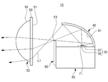
- FIG. 2 is a cross-sectional view of the lamp unit 10 along the light irradiation optical axis.
- the lamp unit 10 includes a heat sink 20, a light source 30 disposed on the heat sink 20, a reflector 40 disposed on the heat sink 20 so as to cover the light source 30 in a semi-dome shape, and a light source 30.
- the lens 50 arrange
- the heat sink 20 is a member that dissipates heat generated by the light source 30 and is preferably formed using a metal material (for example, aluminum) or a resin material having high thermal conductivity. 20 is made of aluminum die casting.
- a semiconductor type light source can be suitably used.
- an LED which is a semiconductor type light source in which a light emitting chip 32 is provided on a substrate 31 on which electric wiring for power feeding (not shown) is formed is used. ing.
- the number of light emitting chips 32 provided on the substrate 31 is not particularly limited, and may be one or plural.
- the shape of the light emitting chip 32 is not particularly limited, and may be square or rectangular. Furthermore, in this embodiment, although the example using LED is shown, you may make it use semiconductor type light sources, such as LD and EL (organic EL).
- the substrate 31 is disposed on the heat sink 20 so that the light emitting surface of the light emitting chip 32 faces upward, and the light from the light source 30 is irradiated upward. ing.
- the reflector 40 is disposed on the heat sink 20 so as to cover the light source 30 in a semi-dome shape, and the light from the light source 30 is reflected to the lens 50 side by the reflecting surface 41 of the reflector 40.
- the material used for the reflector 40 is preferably a metal material (for example, aluminum) or a resin material having a high thermal conductivity and a light-impermeable material.
- a metal material for example, aluminum
- resin material having a high thermal conductivity and a light-impermeable material for example, similar to the heat sink 20, it is made of aluminum die casting. Can be.
- the reflection surface 41 of the reflector 40 is a free-form surface based on a spheroid (ellipse) and has two focal points.
- the reflector 40 is disposed on the heat sink 20 so that the first focal point F1 of the reflecting surface 41 is located near the light emission center of the light source 30 or near the light emission center, and the second focal point F2 is located near the upper end of the shade 60. Has been.
- the lens 50 can be formed using, for example, a transparent resin material such as polycarbonate or acrylic.
- the lens 50 has a circular shape when viewed from the light irradiation direction, and as shown in FIG. 2, the incident surface 51 on which light is incident is planar, and the emission surface 52 from which light is emitted is formed.
- an aspherical lens having an arc shape protruding forward is used, for example, the surface shape of the entrance surface 51 and the exit surface 52 may be formed in another shape such as a free-form surface.
- the incident surface 51 of the lens 50 looks flat as described above when viewed from the exterior, but the incident surface 51 has a light diffusion portion (prism) formed thereon. Accordingly, the incident surface 51 is not a perfect plane because a large number of fine protrusions are formed accurately. This light diffusion part will be described in detail later.
- the lens 50 is provided with a flange 53 on the incident surface 51 side.
- the lens 53 is held by a lens holder (not shown) attached to the heat sink 20, and the rear focus of the lens 50 is the reflector 40.
- the second focal point F2 or the vicinity of the second focal point F2 is disposed.
- the shade 60 can be suitably formed using a light-impermeable material, and the upper end of the shade 60 is positioned in the vicinity of the second focus F of the reflector 40 and the rear focus of the lens 50 as shown in FIG. As shown in FIG.
- FIG. 3 is a perspective view in which the incident surface 51 side of the lens 50 is visible.
- the state of the light diffusing portion is not shown for the incident surface 51, and only the state of the region of the incident surface 51 divided by the state of the light diffusing portion is shown.
- the lens 50 includes an upper incident surface 54 above the center of the incident surface 51 on which light is incident, an intermediate incident surface 55 including the center of the incident surface 51, and a lower side than the intermediate incident surface 55.
- a lower incident surface 56 is shown in FIG. 3, the lens 50.
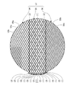
- FIG. 4 is a plan view in which only the incident surface 51 is viewed from the front.
- a first light diffusion portion 54 a that diffuses light is disposed on the upper incident surface 54
- a second light diffusion portion 56 b that diffuses light is disposed on the lower incident surface 56.
- the intermediate incident surface 55 includes a third light diffusing portion 55b and a fourth light diffusing portion 55a for diffusing light
- the intermediate incident surface 55 includes a third light diffusing portion 55b and a fourth light diffusing portion.
- the intermediate incident surface 55 is third in the horizontal direction (left-right direction in the figure).
- a first arrangement pattern portion (1) in which light diffusion portions 55b and fourth light diffusion portions 55a are arranged substantially alternately; a second arrangement pattern portion (2) in which only the transparent portion 55c is arranged in the horizontal direction; And a third arrangement pattern portion (3) in which only the fourth light diffusion portion 55a is arranged in the horizontal direction.
- the intermediate incident surface 55 is positioned substantially at the center of the intermediate incident surface 55 in the vertical direction (vertical direction in the figure).
- the first arrangement pattern portion (1) (see (1) surrounded by a frame) is provided, and the second arrangement pattern portion (2) and the first arrangement pattern are sequentially arranged outward in the vertical direction (outside in the vertical direction in the figure).
- Part (1), third arrangement pattern part (3), first arrangement pattern part (1), third arrangement pattern part (3), first arrangement pattern part (1) and second arrangement pattern part (2). Is provided.
- the third arrangement pattern portion (3) is provided on the uppermost outer side (upper side in the figure) of the intermediate incident surface 55 in the vertical direction (up and down direction in the figure), and the lowermost outer side in the vertical direction of the intermediate incident surface 55 ( A first arrangement pattern portion (1) is provided on the lower side of the drawing.
- the third light diffusing portion 55b is provided so as to be distributed almost uniformly
- the fourth light diffusion portion 55a is provided so as not to be biased as a whole
- the through portion 55c is provided so as not to be biased as a whole.
- the lens 50 is attached due to an attachment error during assembly. Even if the position is slightly shifted, the light diffusion state does not change. For this reason, the intermediate incident surface 55 can obtain a stable light diffusion state.
- the upper incident surface 54 has the first light diffusing portion 54a arranged uniformly on the entire surface
- the lower incident surface 56 has the second light diffusing portion 56b arranged uniformly on the entire surface.
- the intermediate incident surface 55 the upper incident surface 54 and the lower incident surface 56 do not change the light diffusion state even if the mounting position of the lens 50 is slightly shifted due to mounting errors during assembly. For this reason, both the upper incident surface 54 and the lower incident surface 56 can obtain a stable light diffusion state, like the intermediate incident surface 55.
- the first light diffusing unit 54a, the second light diffusing unit 56b, the third light diffusing unit 55b, and the fourth light diffusing unit 55a are all of the same shape.
- the first light diffusing unit 54a, the second light diffusing unit 56b, the third light diffusing unit 55b, and the fourth light diffusing unit 55a are all rhombus-shaped in the direction away from the incident surface 51 (light source 30).
- the prism is a rhombus quadrangular pyramid that protrudes toward the side.
- the fourth light diffusion portion 55a has a rhombus quadrangular pyramid height (projection amount) of 10 ⁇ m, and similarly, the first light diffusion portion 54a has a rhombus quadrangular pyramid height (protrusion amount) of 10 ⁇ m. Yes.
- the first light diffusion portion 54a has the light diffusion width of the fourth light diffusion portion 55a. It is almost the same as the width.
- the third light diffusing portion 55b has a rhombus quadrangular pyramid height (projection amount) of 20 ⁇ m.
- the second light diffusing portion 56b has a rhombus quadrangular pyramid height (protrusion amount) of 20 ⁇ m. Yes. Accordingly, the light diffusion width of the third light diffusion portion 55b is substantially the same as the light diffusion width of the second light diffusion portion 56b.
- the intermediate incident surface 55 is provided with the through portion 55c where the light diffusion portions (the third light diffusion portion 55b and the fourth light diffusion portion 55a) are not disposed. Incident light enters the lens 50 without being diffused.
- the amount of light distribution pattern formed by the light incident on the intermediate incident surface 55 is small.
- the light incident from the portion where the light diffusing portion (the third light diffusing portion 55b and the fourth light diffusing portion 55a) is arranged is diffused by an amount corresponding to the diffusion width of the light diffusing portion, and the inside of the lens 50 is diffused. Is incident on. That is, when light is incident on the lens 50, light incident from a portion of the third light diffusion portion 55b having a large light diffusion width enters the lens 50 with a large diffusion width, and the light diffusion width is small. Light incident from a portion of the small fourth light diffusion portion 55a enters the lens 50 with a small diffusion width.
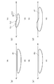
- FIG. 5 is a diagram showing a light distribution pattern on the screen
- FIG. 5 (a) is a diagram showing a light distribution pattern P1 by light incident on the upper incident surface 54
- FIG. 5 (b) is an intermediate incidence
- FIG. 5C is a diagram showing a light distribution pattern P3 by light incident on the lower incident surface 56
- FIG. 5D is a diagram showing a light distribution pattern P2 by light incident on the surface 55.
- FIG. It is a figure which shows the low beam light distribution pattern LP with which the light patterns P1, P2, and P3 were multiplexed.
- the light incident on the upper incident surface 54 (see FIG. 5A) and the lower incident surface 56 (see FIG. 5C) is a diffused light distribution pattern of a low beam light distribution pattern.
- the light incident on the intermediate incident surface 55 (see FIG. 5B) is a condensed light distribution of a low beam light distribution pattern including the upper cutoff line CL1, the oblique cutoff line CL2, and the lower cutoff line CL3.
- a pattern is formed.
- the upper cut-off line CL1, the oblique cut-off line CL2, and the lower cut-off line CL3 may be collectively referred to as a cut-off line CL in some cases.
- the intermediate incident surface 55 has the through portion 55c, and the light incident on the lens 50 from the through portion 55c is not diffused, so the amount of light distribution pattern is reduced.
- the cut-off line CL can be easily viewed.
- FIG. 6 is an enlarged view of a part of the cut-off line CL of the light distribution pattern on the screen formed by the light incident on the intermediate incident surface 55.
- FIG. 6 (a) is for comparison.
- FIG. 6 is a view showing a case where the same light diffusion portion as the third light diffusion portion 55b is arranged on the entire surface of the intermediate incident surface 55 without a gap
- FIG. 6B is a view showing the case of this embodiment. .
- the light diffusion portion is formed on the intermediate incident surface 55, the upper cutoff line CL1, the oblique cutoff line CL2, and the lower cutoff line CL3.
- the light diffused by the light diffusion portion is irradiated on the upper side, and the light distribution spreads to the range indicated by the alternate long and short dash line SL.
- the sudden darkening at the cut-off line CL is alleviated, and the visibility is good for the driver.
- the through portion 55c is provided in the intermediate incident surface 55 as in the present embodiment, the amount of light distribution pattern is reduced accordingly, and the amount of cut-off CL is reduced accordingly.
- the cut-off line CL becomes clearer than in the case of FIG.
- the cut-off line CL becomes easy to visually recognize, workability at the time of adjustment by aiming or the like can be improved.
- the third light diffusion portion 55b having a large light diffusion width and the light diffusion width are Small fourth light diffusion portions 55a are mixed.
- the light diffused by the fourth light diffusing portion 55a having a small light diffusion width is applied to the position indicated by the dotted line SLM between the cut-off line CL and the position indicated by the alternate long and short dash line SL.
- the light quantity gradually decreases from the cut-off line CL toward the one-dot chain line SL.
- the upper incident surface 54, the intermediate incident surface 55, and the lower incident surface 56 shown in FIG. 3 each have a maximum width in the vertical direction (the vertical direction in the figure), and the vertical direction of the incident surface 51.
- the intermediate incident surface 55 has a width (maximum width) in the vertical direction (up and down direction) of the intermediate incident surface 55 that is 20% or more and 45% or less of the maximum width in the vertical direction of the incident surface 51.
- the intermediate incident surface 55 is set so that a substantially middle (center) portion of the width in the vertical direction is located at the center of the incident surface 51.
- the light diffusing unit (the first light diffusing unit 54a, the second light diffusing unit 56b, the third light diffusing unit 55b, and the fourth light diffusing unit 55a)
- the prism is not necessarily limited to a rhombus, and may be formed as a prism such as a regular quadrangular pyramid whose bottom is a regular square. May be changed.
- the height (projection amount) of the light diffusing sections is also the height specifically shown above. There is no need to be limited. As described above, the height (protrusion amount) of the light diffusion portion (the first light diffusion portion 54a, the second light diffusion portion 56b, the third light diffusion portion 55b, and the fourth light diffusion portion 55a) is increased (the protrusion amount is reduced). If the height is larger, the light diffusion width becomes larger, and conversely, if the height (projection amount) is lowered (projection amount is smaller), the light diffusion width becomes smaller. The height (projection amount) of the light diffusing part (the first light diffusing part 54a, the second light diffusing part 56b, the third light diffusing part 55b, and the fourth light diffusing part 55a) is adjusted so as to be suitable for Also good.
- the height (projection amount) of the first light diffusion portion 54a is preferably 10 ⁇ m or less.
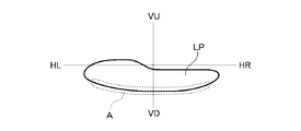
- FIG. 7 is a diagram showing the low beam light distribution pattern LP of FIG. 5D, that is, a diagram showing the light distribution pattern of the vehicular lamp of the embodiment.
- the light incident from the lower side of the lower incident surface 56 where the light passing through the lower side of the lens 50 is incident forms the lower side of the low beam light distribution pattern LP.
- the second light diffusing portion 56b is provided uniformly on almost the entire lower incident surface 56, the light irradiated below the low beam light distribution pattern LP is also diffused. It has become.
- the lower side of the low-beam light distribution pattern LP is a light distribution portion that illuminates the immediate vicinity of the vehicle 102. Therefore, if the irradiated light group has light intensity unevenness, the state of light intensity unevenness is likely to appear. In some cases, light intensity unevenness due to light diffusion by the second light diffusing unit 56b may appear below the low beam light distribution pattern LP like the region A surrounded by the dotted line shown in FIG. Therefore, in order to suppress such light intensity unevenness, it is preferable not to arrange the second light diffusion portion 56 b in the lower portion of the lower incident surface 56.
- FIG. 8 is a view showing a modified example of the incident surface 51 of the lens 50, and more specifically, a diagram showing a case where the second light diffusion portion 56b is not disposed in the lower portion of the lower incident surface 56.
- FIG. 8 on the lower incident surface 56, when the widest width in the vertical direction (the vertical direction in the figure) is the lower incident surface width, ) So that the second light diffusing portion 56b is arranged without a gap in a region that is substantially half of the width of the lower incident surface, and the remaining region of the lower incident surface 56 is formed by the second light diffusing portion 56b.
- the threading portion 56c is not arranged.
- the present invention has been described based on the specific embodiments, the present invention is not limited to the above embodiments.
- the vehicle lamp for left-side traveling has been illustrated and described.
- the light diffusing portion provided on the entrance surface of the lens is configured as described above, the same applies. Therefore, the present invention is not limited to the vehicular lamp for driving on the left side.
Landscapes
- Engineering & Computer Science (AREA)
- General Engineering & Computer Science (AREA)
- Physics & Mathematics (AREA)
- Optics & Photonics (AREA)
- Microelectronics & Electronic Packaging (AREA)
- Non-Portable Lighting Devices Or Systems Thereof (AREA)
Abstract
La présente invention a pour objectif de fournir un éclairage de véhicule permettant de minimiser une irrégularité dans la distribution de lumière apparaissant sur une surface de route en prenant en compte la maniabilité lors d'un ajustement par pointage ou analogue. L'éclairage de véhicule de la présente invention forme une distribution de lumière ayant une ligne de coupure CL et comprend une source de lumière (30) ainsi qu'une lentille (50) disposée sur le côté avant de la source de lumière (30). La surface d'entrée (51) de la lentille (50) où pénètre la lumière de la source lumineuse (30) comprend : une surface d'entrée latérale supérieure (54) sur un côté supérieur depuis le centre de la surface d'entrée (51), ladite surface d'entrée latérale supérieure incluant des premières parties de diffusion de lumière (54a) permettant de diffuser la lumière ; une surface d'entrée latérale inférieure (56) sur un côté inférieur depuis le centre de la surface d'entrée (51), ladite surface d'entrée latérale inférieure incluant des deuxièmes parties de diffusion de lumière (56) permettant de diffuser la lumière ; et une surface d'entrée centrale (55) englobant le centre de la surface d'entrée, ladite surface d'entrée centrale incluant des troisièmes parties de diffusion de lumière (55b) et des quatrièmes parties de diffusion de lumière (55a) permettant de diffuser la lumière, et incluant également des parties droites traversantes (55c) où ne se trouvent aucune des troisièmes parties de diffusion de lumière (55b) et des quatrièmes parties de diffusion de lumière (55a). La largeur de diffusion de lumière pour chacune des troisièmes parties de diffusion de lumière (55b) est plus grande que la largeur de diffusion de lumière pour chacune des quatrièmes parties de diffusion de lumière (55a).
Priority Applications (3)
| Application Number | Priority Date | Filing Date | Title |
|---|---|---|---|
| CN201780009988.XA CN108603646B (zh) | 2016-02-04 | 2017-02-03 | 车辆用灯具 |
| EP17747586.0A EP3412959B1 (fr) | 2016-02-04 | 2017-02-03 | Éclairage de véhicule |
| US16/075,424 US10359167B2 (en) | 2016-02-04 | 2017-02-03 | Vehicular lighting |
Applications Claiming Priority (2)
| Application Number | Priority Date | Filing Date | Title |
|---|---|---|---|
| JP2016019572A JP6705192B2 (ja) | 2016-02-04 | 2016-02-04 | 車両用灯具 |
| JP2016-019572 | 2016-09-09 |
Publications (1)
| Publication Number | Publication Date |
|---|---|
| WO2017135435A1 true WO2017135435A1 (fr) | 2017-08-10 |
Family
ID=59499825
Family Applications (1)
| Application Number | Title | Priority Date | Filing Date |
|---|---|---|---|
| PCT/JP2017/004056 Ceased WO2017135435A1 (fr) | 2016-02-04 | 2017-02-03 | Éclairage de véhicule |
Country Status (5)
| Country | Link |
|---|---|
| US (1) | US10359167B2 (fr) |
| EP (1) | EP3412959B1 (fr) |
| JP (1) | JP6705192B2 (fr) |
| CN (1) | CN108603646B (fr) |
| WO (1) | WO2017135435A1 (fr) |
Cited By (1)
| Publication number | Priority date | Publication date | Assignee | Title |
|---|---|---|---|---|
| CN113339750A (zh) * | 2018-03-15 | 2021-09-03 | 株式会社小糸制作所 | 车辆用前照灯 |
Families Citing this family (6)
| Publication number | Priority date | Publication date | Assignee | Title |
|---|---|---|---|---|
| JP7131250B2 (ja) * | 2018-09-26 | 2022-09-06 | 市光工業株式会社 | 車両用灯具 |
| CN111486403A (zh) * | 2019-07-11 | 2020-08-04 | 华域视觉科技(上海)有限公司 | 一种形成近光ⅲ区光形的透镜、车辆照明装置及汽车 |
| CN110160003B (zh) * | 2019-06-11 | 2021-05-04 | 海纳川海拉(天津)车灯有限公司 | 一种汽车大灯自动调节机构 |
| EP3974709A1 (fr) * | 2020-09-25 | 2022-03-30 | ZKW Group GmbH | Dispositif d'éclairage pour un phare de véhicule automobile |
| JP2024134838A (ja) * | 2023-03-22 | 2024-10-04 | 株式会社小糸製作所 | 車両用灯具 |
| KR20260044015A (ko) * | 2024-09-25 | 2026-04-01 | 현대모비스 주식회사 | 차량용 램프 |
Citations (3)
| Publication number | Priority date | Publication date | Assignee | Title |
|---|---|---|---|---|
| JP2008262755A (ja) * | 2007-04-10 | 2008-10-30 | Koito Mfg Co Ltd | 車両用灯具ユニット |
| JP2014157733A (ja) | 2013-02-15 | 2014-08-28 | Ichikoh Ind Ltd | 車両用灯具 |
| JP2016213023A (ja) * | 2015-05-07 | 2016-12-15 | 市光工業株式会社 | 車両用灯具 |
Family Cites Families (17)
| Publication number | Priority date | Publication date | Assignee | Title |
|---|---|---|---|---|
| JP3218551B2 (ja) * | 1993-08-27 | 2001-10-15 | スタンレー電気株式会社 | 車両用信号灯具 |
| JP4279936B2 (ja) * | 1999-03-30 | 2009-06-17 | サカエ理研工業株式会社 | ランプ用リフレクタ |
| JP2003161988A (ja) * | 2001-11-28 | 2003-06-06 | Fuji Photo Film Co Ltd | 複合反射板ストロボ及びデジタルカメラ |
| KR100542058B1 (ko) * | 2002-12-06 | 2006-01-11 | 주식회사 에스엘 엘씨디 | 차량용 램프 |
| JP4597890B2 (ja) * | 2006-03-29 | 2010-12-15 | 株式会社小糸製作所 | 車両用前照灯の灯具ユニット |
| JP4964753B2 (ja) * | 2007-12-12 | 2012-07-04 | 株式会社小糸製作所 | 車両用照明灯具 |
| JP5235502B2 (ja) * | 2008-05-28 | 2013-07-10 | 株式会社小糸製作所 | 車両用照明灯具 |
| JP5342334B2 (ja) * | 2009-06-10 | 2013-11-13 | 株式会社小糸製作所 | 車両用灯具 |
| KR101248776B1 (ko) * | 2011-02-10 | 2013-04-24 | 주식회사 세코닉스 | 전조등용 프로젝션 렌즈 및 이를 구비한 차량용 전조등 유닛 |
| CN105842762B (zh) * | 2011-08-12 | 2018-06-12 | 西铁城电子株式会社 | 透镜以及使用该透镜的发光装置 |
| EP3056385B1 (fr) * | 2011-09-01 | 2018-06-06 | Koito Manufacturing Co., Ltd. | Appareil de phare automobile |
| US9033562B2 (en) * | 2011-12-27 | 2015-05-19 | Ichikoh Industries, Ltd. | Vehicle headlamp |
| JP6180091B2 (ja) * | 2012-09-07 | 2017-08-16 | 株式会社小糸製作所 | 車両用灯具 |
| JP6028487B2 (ja) * | 2012-09-20 | 2016-11-16 | 市光工業株式会社 | 車両用灯具 |
| CN103062698B (zh) * | 2013-01-30 | 2016-03-30 | 上海开腾信号设备有限公司 | 地面交通工具区域对应指向配光型led灯及其制造方法 |
| JP6232225B2 (ja) * | 2013-08-09 | 2017-11-15 | 株式会社小糸製作所 | 車両用灯具 |
| US10054277B2 (en) * | 2014-09-16 | 2018-08-21 | Koito Manufacturing Co., Ltd. | Vehicle lamp |
-
2016
- 2016-02-04 JP JP2016019572A patent/JP6705192B2/ja active Active
-
2017
- 2017-02-03 WO PCT/JP2017/004056 patent/WO2017135435A1/fr not_active Ceased
- 2017-02-03 US US16/075,424 patent/US10359167B2/en active Active
- 2017-02-03 EP EP17747586.0A patent/EP3412959B1/fr active Active
- 2017-02-03 CN CN201780009988.XA patent/CN108603646B/zh active Active
Patent Citations (3)
| Publication number | Priority date | Publication date | Assignee | Title |
|---|---|---|---|---|
| JP2008262755A (ja) * | 2007-04-10 | 2008-10-30 | Koito Mfg Co Ltd | 車両用灯具ユニット |
| JP2014157733A (ja) | 2013-02-15 | 2014-08-28 | Ichikoh Ind Ltd | 車両用灯具 |
| JP2016213023A (ja) * | 2015-05-07 | 2016-12-15 | 市光工業株式会社 | 車両用灯具 |
Non-Patent Citations (1)
| Title |
|---|
| See also references of EP3412959A4 * |
Cited By (1)
| Publication number | Priority date | Publication date | Assignee | Title |
|---|---|---|---|---|
| CN113339750A (zh) * | 2018-03-15 | 2021-09-03 | 株式会社小糸制作所 | 车辆用前照灯 |
Also Published As
| Publication number | Publication date |
|---|---|
| US10359167B2 (en) | 2019-07-23 |
| CN108603646A (zh) | 2018-09-28 |
| JP6705192B2 (ja) | 2020-06-03 |
| EP3412959A4 (fr) | 2019-10-23 |
| JP2017139146A (ja) | 2017-08-10 |
| CN108603646B (zh) | 2020-08-14 |
| EP3412959A1 (fr) | 2018-12-12 |
| US20190041021A1 (en) | 2019-02-07 |
| EP3412959B1 (fr) | 2021-06-02 |
Similar Documents
| Publication | Publication Date | Title |
|---|---|---|
| CN106662314B (zh) | 灯具单元及车辆用前照灯 | |
| CN108474532B (zh) | 车辆用灯具和基板 | |
| JP6705192B2 (ja) | 車両用灯具 | |
| KR101393659B1 (ko) | 차량용 전조등 | |
| JP6582524B2 (ja) | 車両用灯具 | |
| JP5277823B2 (ja) | 車両用前照灯 | |
| JP6028487B2 (ja) | 車両用灯具 | |
| EP4053447A1 (fr) | Guide optique de véhicule et phare de véhicule | |
| CN112135998A (zh) | 车辆用灯具 | |
| JP6713869B2 (ja) | 車両用灯具 | |
| JP2012169050A (ja) | 車両用灯具 | |
| CN101285561A (zh) | 车辆用灯具单元 | |
| JP2012089333A (ja) | 車両用灯具 | |
| JP6030864B2 (ja) | 灯具ユニットおよび投影レンズ | |
| EP2570715A2 (fr) | Phare de véhicule | |
| JP2011025820A (ja) | 車両用灯具 | |
| JP2011181277A (ja) | 車両用前照灯 | |
| JP2014041802A (ja) | 車両用前照灯 | |
| JP2011181279A (ja) | 車両用前照灯 | |
| JP2011108412A (ja) | 車両用灯具 | |
| JP2024046345A (ja) | 車両用灯具 | |
| JP2014102941A (ja) | 車両用前照灯 | |
| JP7131250B2 (ja) | 車両用灯具 | |
| JP2013196902A (ja) | 車両用前照灯 | |
| JP2016157527A (ja) | 車両用灯具 |
Legal Events
| Date | Code | Title | Description |
|---|---|---|---|
| 121 | Ep: the epo has been informed by wipo that ep was designated in this application |
Ref document number: 17747586 Country of ref document: EP Kind code of ref document: A1 |
|
| NENP | Non-entry into the national phase |
Ref country code: DE |
|
| WWE | Wipo information: entry into national phase |
Ref document number: 2017747586 Country of ref document: EP |
|
| ENP | Entry into the national phase |
Ref document number: 2017747586 Country of ref document: EP Effective date: 20180904 |