WO2017135442A1 - Échangeur de chaleur - Google Patents
Échangeur de chaleur Download PDFInfo
- Publication number
- WO2017135442A1 WO2017135442A1 PCT/JP2017/004075 JP2017004075W WO2017135442A1 WO 2017135442 A1 WO2017135442 A1 WO 2017135442A1 JP 2017004075 W JP2017004075 W JP 2017004075W WO 2017135442 A1 WO2017135442 A1 WO 2017135442A1
- Authority
- WO
- WIPO (PCT)
- Prior art keywords
- fin
- refrigerant
- heat transfer
- mounting portion
- heat exchanger
- Prior art date
- Legal status (The legal status is an assumption and is not a legal conclusion. Google has not performed a legal analysis and makes no representation as to the accuracy of the status listed.)
- Ceased
Links
Images



Classifications
-
- F—MECHANICAL ENGINEERING; LIGHTING; HEATING; WEAPONS; BLASTING
- F24—HEATING; RANGES; VENTILATING
- F24F—AIR-CONDITIONING; AIR-HUMIDIFICATION; VENTILATION; USE OF AIR CURRENTS FOR SCREENING
- F24F1/00—Room units for air-conditioning, e.g. separate or self-contained units or units receiving primary air from a central station
- F24F1/06—Separate outdoor units, e.g. outdoor unit to be linked to a separate room comprising a compressor and a heat exchanger
- F24F1/14—Heat exchangers specially adapted for separate outdoor units
- F24F1/18—Heat exchangers specially adapted for separate outdoor units characterised by their shape
-
- F—MECHANICAL ENGINEERING; LIGHTING; HEATING; WEAPONS; BLASTING
- F25—REFRIGERATION OR COOLING; COMBINED HEATING AND REFRIGERATION SYSTEMS; HEAT PUMP SYSTEMS; MANUFACTURE OR STORAGE OF ICE; LIQUEFACTION SOLIDIFICATION OF GASES
- F25B—REFRIGERATION MACHINES, PLANTS OR SYSTEMS; COMBINED HEATING AND REFRIGERATION SYSTEMS; HEAT PUMP SYSTEMS
- F25B39/00—Evaporators; Condensers
-
- F—MECHANICAL ENGINEERING; LIGHTING; HEATING; WEAPONS; BLASTING
- F25—REFRIGERATION OR COOLING; COMBINED HEATING AND REFRIGERATION SYSTEMS; HEAT PUMP SYSTEMS; MANUFACTURE OR STORAGE OF ICE; LIQUEFACTION SOLIDIFICATION OF GASES
- F25B—REFRIGERATION MACHINES, PLANTS OR SYSTEMS; COMBINED HEATING AND REFRIGERATION SYSTEMS; HEAT PUMP SYSTEMS
- F25B39/00—Evaporators; Condensers
- F25B39/04—Condensers
-
- F—MECHANICAL ENGINEERING; LIGHTING; HEATING; WEAPONS; BLASTING
- F28—HEAT EXCHANGE IN GENERAL
- F28D—HEAT-EXCHANGE APPARATUS, NOT PROVIDED FOR IN ANOTHER SUBCLASS, IN WHICH THE HEAT-EXCHANGE MEDIA DO NOT COME INTO DIRECT CONTACT
- F28D1/00—Heat-exchange apparatus having stationary conduit assemblies for one heat-exchange medium only, the media being in contact with different sides of the conduit wall, in which the other heat-exchange medium is a large body of fluid, e.g. domestic or motor car radiators
- F28D1/02—Heat-exchange apparatus having stationary conduit assemblies for one heat-exchange medium only, the media being in contact with different sides of the conduit wall, in which the other heat-exchange medium is a large body of fluid, e.g. domestic or motor car radiators with heat-exchange conduits immersed in the body of fluid
- F28D1/04—Heat-exchange apparatus having stationary conduit assemblies for one heat-exchange medium only, the media being in contact with different sides of the conduit wall, in which the other heat-exchange medium is a large body of fluid, e.g. domestic or motor car radiators with heat-exchange conduits immersed in the body of fluid with tubular conduits
- F28D1/047—Heat-exchange apparatus having stationary conduit assemblies for one heat-exchange medium only, the media being in contact with different sides of the conduit wall, in which the other heat-exchange medium is a large body of fluid, e.g. domestic or motor car radiators with heat-exchange conduits immersed in the body of fluid with tubular conduits the conduits being bent, e.g. in a serpentine or zig-zag
Definitions
- the present invention relates to a heat exchanger, and more particularly, to a heat exchanger that is mounted for an outdoor unit of a refrigeration apparatus using a flat tube.
- the above heat exchanger has a structure in which the gas refrigerant flows into the upper part of the header located on the windward side of the passing air flow and the liquid refrigerant flows out from the lower part of the header that is also located on the windward side. Is on the windward side, which tends to cause a decrease in heat exchange performance.
- An object of the present invention is to provide a heat exchanger that prevents deterioration in heat exchange performance in a plurality of rows of microchannel heat exchangers.
- a heat exchanger includes a first heat transfer fin group and a second heat transfer fin group, and a pipe through which a refrigerant passes, the first heat transfer fin group and the second heat transfer fin. And a refrigerant pipe having a flat tube on which the fin group is mounted.
- the refrigerant pipe has a first fin mounting portion, a second fin mounting portion, a first fin non-mounting portion, a second fin non-mounting portion, and a third fin non-mounting portion.
- the first heat transfer fin group is mounted on the first fin mounting portion.
- a second heat transfer fin group is mounted on the second fin mounting portion.
- the first fin non-mounting portion is located between the first fin mounting portion and the second fin mounting portion.
- the second fin non-mounting portion is located on the opposite side of the first fin non-mounting portion across the first fin mounting portion.
- the third fin non-mounting portion is located on the opposite side of the first fin non-mounting portion across the second fin mounting portion.
- the first fin non-mounting portion includes a first bent portion where the refrigerant pipe is bent so that the first heat transfer fin group and the second heat transfer fin group face each other.
- the second fin non-mounting portion includes a refrigerant inlet portion and a second bent portion where the refrigerant pipe exits from the first heat transfer fin group and returns to the first heat transfer fin group.
- the third fin non-mounting portion includes a refrigerant outlet portion and a third bent portion where the refrigerant pipe exits from the second heat transfer fin group and returns to the second heat transfer fin group.
- the refrigerant inlet portion and the refrigerant outlet portion can be diagonally arranged in the developed shape before the first bent portion is formed. Therefore, the refrigerant inlet portion and the refrigerant outlet portion can be arranged in different rows. it can.
- the refrigerant inlet portion and the refrigerant outlet portion can be arranged by distinguishing between the windward side and the leeward side of the air flow passing through the heat exchanger. Therefore, for example, when it is advantageous to improve the performance to arrange the refrigerant inlet portion on the leeward side, it can be arranged as such.
- the heat exchanger which concerns on the 2nd viewpoint of this invention is a heat exchanger which concerns on a 1st viewpoint, Comprising: As the mutually opposing surface of a 1st heat-transfer fin group and a 2nd heat-transfer fin group follows a perpendicular direction. Is arranged.
- the refrigerant inlet portion which is an inlet for the gas refrigerant, is positioned upward in the vertical direction.
- the refrigerant outlet part which is the outlet of the liquid refrigerant, is located downward in the vertical direction.
- the flow of the refrigerant is a flow from the top to the bottom, hardly affected by gravity, and the drift is suppressed.
- the heat exchanger according to the third aspect of the present invention is arranged such that the refrigerant inlet is located on the leeward side of the refrigerant outlet with respect to the air flow.
- a heat exchanger is the heat exchanger according to any one of the first to third aspects, wherein two rows of refrigerant pipes are arranged in parallel by forming the first bent portion. Is made. Furthermore, the refrigerant pipes are arranged so that the two rows are along the air flow direction. The refrigerant inlet portion is connected to a row located on the leeward side of the air flow in the two rows.
- the refrigerant inlet portion and the refrigerant outlet portion can be diagonally arranged in the developed shape before the first bent portion is formed. Can be arranged in different columns.
- the refrigerant inlet portion and the refrigerant outlet portion can be arranged by distinguishing between the windward side and the leeward side of the air flow passing through the heat exchanger. Therefore, for example, when it is advantageous to improve the performance to arrange the refrigerant inlet portion on the leeward side, it can be arranged as such.
- the refrigerant flow is a flow from the top to the bottom, hardly affected by gravity, and the drift is suppressed. .
- the refrigerant inlet portion into which the high-temperature refrigerant flows becomes leeward, it is avoided that the air is heated excessively on the windward side. That is, the heat exchange between [the air heated excessively on the windward side] and the refrigerant is suppressed, and the heat exchange performance is improved.
- FIG. 5 is a perspective view of the left side plate, the outdoor heat exchanger, and the outdoor fan when the left side plate, the outdoor heat exchanger, and the outdoor fan that are disposed at regular positions are viewed from a different angle from that of FIG. 4.
- FIG. 1 is a configuration diagram of a refrigeration apparatus 1 that uses an outdoor heat exchanger 25 that is a heat exchanger according to an embodiment of the present invention.
- a refrigeration apparatus 1 is an air conditioner capable of cooling operation and heating operation, and a liquid refrigerant communication pipe for connecting an outdoor unit 3, an indoor unit 2, and the outdoor unit 3 and the indoor unit 2. 7 and a gas refrigerant communication pipe 9.
- the indoor unit 2 includes an indoor heat exchanger 11 and an indoor fan 13.
- the indoor heat exchanger 11 is a cross fin type heat exchanger, and can evaporate or condense the refrigerant flowing inside by heat exchange with indoor air, thereby cooling or heating indoor air.
- the outdoor unit 3 mainly includes a compressor 21, a four-way switching valve 23, an outdoor heat exchanger 25, an expansion valve 27, an accumulator 29, a liquid side closing valve 37, and a gas side closing valve 39. ing. Furthermore, the outdoor unit 3 also has an outdoor fan 41.
- the four-way switching valve 23 switches the direction of the refrigerant flow when switching between the cooling operation and the heating operation. During the cooling operation, the four-way switching valve 23 connects the discharge side of the compressor 21 and the gas side of the outdoor heat exchanger 25 and connects the suction side of the compressor 21 and the gas side closing valve 39. That is, this is the state indicated by the solid line in the four-way selector valve 23 in FIG.
- the four-way switching valve 23 connects the discharge side of the compressor 21 and the gas side closing valve 39 and connects the suction side of the compressor 21 and the gas side of the outdoor heat exchanger 25. That is, this is the state indicated by the dotted line in the four-way selector valve 23 of FIG.
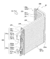
- FIG. 2 is an external perspective view of the outdoor heat exchanger 25.
- the outdoor heat exchanger 25 is a two-row microchannel heat exchanger, and can condense or evaporate the refrigerant flowing inside by heat exchange with outdoor air. The detailed configuration of the outdoor heat exchanger 25 will be described later.
- Expansion valve 27 The expansion valve 27 is connected to a pipe between the outdoor heat exchanger 25 and the liquid side shut-off valve 37 in order to adjust the refrigerant pressure and the refrigerant flow rate, so that the refrigerant can be used in both the cooling operation and the heating operation. Has the function of expanding.
- the liquid side closing valve 37 and the gas side closing valve 39 are connected to the liquid refrigerant communication pipe 7 and the gas refrigerant communication pipe 9, respectively.
- the liquid refrigerant communication pipe 7 connects between the liquid side of the indoor heat exchanger 11 of the indoor unit 2 and the liquid side shut-off valve 37 of the outdoor unit 3.
- the gas refrigerant communication pipe 9 connects between the gas side of the indoor heat exchanger 11 of the indoor unit 2 and the gas side closing valve 39 of the outdoor unit 3.
- the refrigerant flows in the order of the compressor 21, the outdoor heat exchanger 25, the expansion valve 27, and the indoor heat exchanger 11 during the cooling operation, and the compressor 21, the indoor heat exchanger 11, the expansion valve 27, and the outdoor heat during the heating operation.
- a refrigeration circuit through which the refrigerant flows in the order of the exchanger 25 is formed.
- FIG. 3 is a plan view of the outdoor unit 3, in which the top plate is removed and the inside is shown in a plan view.
- FIG. 4 is a perspective view of the left side plate 917, the outdoor heat exchanger 25, and the outdoor fan 41 that are disposed at regular positions. 5 shows the left side plate 917, the outdoor heat exchanger 25, and the outdoor fan when the left side plate 917, the outdoor heat exchanger 25, and the outdoor fan 41 arranged at regular positions are viewed from a different angle from FIG. FIG.
- the outdoor unit 3 includes a vapor compression refrigeration cycle such as an outdoor fan 41, a compressor 21, an outdoor heat exchanger 25, and piping in a main body casing 91 that forms an outer shell.
- a vapor compression refrigeration cycle such as an outdoor fan 41, a compressor 21, an outdoor heat exchanger 25, and piping in a main body casing 91 that forms an outer shell.
- the members necessary for the configuration are housed.
- the main body casing 91 has a substantially rectangular parallelepiped shape by a top plate 911 (see FIG. 5), a bottom plate 913, a base leg 915, a left side plate 917, a first front plate 919, a second front plate 921, a right side plate 923, and a suction grill 925. It is formed into a shape. Further, the top plate 911, the bottom plate 913, the base leg 915, the left side plate 917, the first front plate 919, the second front plate 921, and the right side plate 923 are steel sheet metal working members.
- the inside of the main body casing 91 is divided into a machine chamber 91a and a blower chamber 91b by a vertically extending partition plate 927, the compressor 21 in the machine chamber 91a, the outdoor heat exchanger 25 and the outdoor fan 41 in the blower chamber 91b. Is stored.
- FIG. 3 when the outdoor fan 41 is operating, air is sucked from the directions of B and C, and is exchanged with the outdoor heat exchanger 25 and then blown out in the direction of A.
- Outdoor fan 41 4 and 5 the outdoor fan 41 is a propeller fan having a plurality of blades, and is arranged to face the air outlet 919a (see FIG. 3) on the front side of the outdoor heat exchanger 25 in the blower chamber 91b. Has been.
- the outdoor fan 41 is rotationally driven by a fan motor 41a.
- the fan motor 41 a is attached to the motor fixing base 71.
- the motor fixing base 71 is a structure in which an upper end flat part 711 (see FIG. 4) and a lower end flat part 713 (see FIG. 5) are connected by four support bars 715.
- the fan motor 41 a is fixed to the central portion in the vertical direction of the motor fixing base 71.
- the outdoor heat exchanger 25 includes a refrigerant pipe 250, a first heat transfer fin group 255, a second heat transfer fin group 256, an anticorrosion member 260, and a pipe.
- a plate 270 is included.
- the refrigerant pipe 250 includes a flat tube 251, an inlet header 253, an outlet header 257, and the like.
- the first heat transfer fin group 255 and the second heat transfer fin group 256 are aggregates of heat transfer fins 255a which are unit elements.
- the flat tube 251 is meanderingly formed of aluminum or an aluminum alloy, has a flat portion 251a serving as a heat transfer surface, and further includes a first bent portion 250b, a second bent portion 251b, and a third bent portion as a folded portion. It has a bent portion 252b.
- a plurality of microchannels (not shown) through which the refrigerant flows are formed inside the flat tube 251.
- the flat tube 251 is disposed with the flat portion 251a facing up and down.
- the outdoor heat exchanger 25 is bent by 180 ° around a vertical axis at a predetermined location and formed into a two-row structure.
- FIG. 6 is a schematic side view of the outdoor heat exchanger 25 before being folded in half. 2 and 6, the four flat tubes 251 are folded four times so as to meander while maintaining an equal interval.
- the flat tube 251 is provided with two fin mounting portions on which a group of heat transfer fins 255a are mounted, spaced apart by a certain length, one being a first fin mounting portion 251x and the other being a second fin mounting portion. 252x.
- the heat transfer fin 255a is not mounted between the first fin mounting portion 251x and the second fin mounting portion 252x, and this portion is referred to as a first fin non-mounting portion 250y.
- the first fin non-mounting portion 250y is formed by bending the flat tube 251 so that the first heat transfer fin group 255 and the second heat transfer fin group face each other. Is formed.
- the first bent portion 250b is formed by being bent by 180 ° around the Z axis (vertical axis).
- the present invention is not limited to this, and the fact that the first heat transfer fin group 255 and the second heat transfer fin group 256 are opposed to each other is the internal angle formed by the first heat transfer fin group 255 and the second heat transfer fin group. It may be opposite so that becomes an obtuse angle.
- the first bent portion 250b has a three-dimensional U shape in which the direction of the flat portion of the flat tube 251 changes during the bending.
- the heat transfer fin 255a is not mounted on the flat tube 251 located on the opposite side of the first fin non-mounting portion 250y across the first fin mounting portion 251x, and this portion is not attached to the second fin non-mounting portion 251y. That's it.
- the second fin non-mounting portion 251y includes a flat tube 251 connected to the inlet header 253 and two second bent portions 251b for folding. The two second bent portions 251b exit from the first heat transfer fin group 255, are folded back, and return to the first heat transfer fin group 255.
- the one closer to the inlet header 253 is called a second bent portion A251ba, and the one farther from the inlet header 253 is called a second bent portion B251bb. Since the flat tube 251 connected to the inlet header 253 is not folded, it is called a non-folded portion 251c.
- the heat transfer fin 255a is not mounted on the flat tube 251 located on the opposite side of the first fin non-mounting portion 250y across the second fin mounting portion 252x, and this portion is connected to the third fin non-mounting portion 252y. That's it.
- the third fin non-mounting portion 252y includes a flat tube 251 connected to the outlet header 257 and two third bent portions 252b for folding. The two third bent portions 252b exit from the second heat transfer fin group 256, are folded back, and return to the second heat transfer fin group 256.
- the one far from the outlet header 257 is called a third bent portion A252ba, and the one closer to the outlet header 257 is called a third bent portion B252bb. Since the flat tube 251 connected to the outlet header 257 is not folded, it is called a non-folded portion 252c.
- the 1st bending part 250b, the 2nd bending part 251b, and the 3rd bending part 252b are formed when the flat tube 251 is folded back, it is not limited to it.
- each bending part is formed by connecting the flat tube 251 to a circular tube, and bend
- the heat transfer fin 255a is a fin made of aluminum or aluminum alloy bent into a corrugated shape.
- the heat transfer fins 255a are arranged in a ventilation space sandwiched between the flat portions 251a of the flat tubes 251 adjacent vertically, and the valley portions and the mountain portions are in contact with the flat portions 251a of the flat tubes 251.
- the trough part, the peak part, and the plane part 251a are brazed and welded.
- the group of heat transfer fins 255a attached to the first fin attachment portion 251x of the flat tube 251 is referred to as a first heat transfer fin group 255.
- the group of heat transfer fins 255a attached to the second fin attachment portion 252x of the flat tube 251 is referred to as a second heat transfer fin group 256.
- the inlet header 253 is a hollow cylindrical tube.
- the inlet header 253 is connected to one end of a plurality of flat tubes 251 arranged at regular intervals in the vertical direction. Further, the inlet header 253 has a function of supporting the flat tube 251, a function of guiding the refrigerant to the microchannel in the flat tube 251, and a function of collecting the refrigerant that has come out of the microchannel.
- the exit header 257 is a hollow cylindrical tube similar to the entrance header 253.
- the outlet header 257 is connected to the other end of the plurality of flat tubes 251 arranged at regular intervals in the vertical direction.
- the outlet header 257 has a function of supporting the flat tube 251, a function of guiding the refrigerant to the microchannel in the flat tube 251, and a function of collecting the refrigerant that has come out of the microchannel. Have.
- Anticorrosion member 260 As shown in FIGS. 4 and 5, a plate-shaped anticorrosion member 260 is attached between the first fin non-mounting portion 250 y (first bent portion 250 b) of the flat tube 251 and the left side plate 917.
- the anticorrosion member 260 prevents the first fin non-mounting portion 250y from being exposed to the air flow and suppresses the progress of corrosion.
- the first bent portion 250b of the first fin non-mounting portion 250y is close to the side suction port 917c (see FIG. 5) of the left side plate 917 in the blower chamber 91b. Exposed to the stream.
- the second fin non-mounting portion 251y and the third fin non-mounting portion 252y are located in the machine room 91a and are not exposed to the air flow.
- the corrosion of the first fin non-mounting portion 250y exposed to the air flow is faster than the second fin non-mounting portion 251y and the third fin non-mounting portion 252y that are not exposed to the air flow.
- the potential decreases in the order of the flat tube 251, the anticorrosion member 260, and the brazing material. Therefore, the anticorrosion member 260 exhibits a sacrificial anticorrosion effect with respect to the flat tube 251, and the brazing material exhibits a sacrificial anticorrosion effect with respect to the anticorrosion member 260 and the flat tube 251.
- Tube sheet 270 As shown in FIGS. 2 to 4, the second fin non-mounting portion 251y and the third fin non-mounting portion 252y on the opposite side of the anticorrosion member 260 across the first fin mounting portion 251x and the second fin mounting portion 252x A tube plate 270 is attached.
- the tube plate 270 includes a first heat transfer fin group 255 and a second heat transfer fin group 256, which are a group of heat transfer fins 255a attached to the first fin attachment portion 251x and the second fin attachment portion 252x, and the anticorrosion member 260. It is arranged to be sandwiched between.
- the tube plate 270 is brazed to the flat tube 251 by the second fin non-mounting portion 251y and the third fin non-mounting portion 252y.
- a partition plate 927 that divides the inside of the main body casing 91 into a machine chamber 91 a and a blower chamber 91 b extends from the boundary between the first front plate 919 and the second front plate 921, and the end thereof is the tube plate 270 of the outdoor heat exchanger 25. It approaches. And the clearance gap between the outdoor heat exchanger 25 and the back side of the main body casing 91 is divided by the tube sheet 270 into the machine room 91a and the air blower room 91b. That is, the tube sheet 270 also has a function as a partition member.
- the flat portion 251a of the flat tube 251 is arranged so that its normal line is along the vertical axis and is bent in an L shape, so that the vertical axis is the Z axis.
- An axis parallel to the long side of the L shape and perpendicular to the Z axis is defined as a Y axis, and an axis orthogonal to both the axes is defined as an X axis.
- the refrigerant flows into the inlet header 253 from the refrigerant inlet 253a located at the upper left side of the leeward row with respect to the air flow.
- the refrigerant flowing into the inlet header 253 is distributed substantially evenly to the internal flow paths (microchannels) of the first, second, third, and fourth flat tubes 251 from the top, and the first folded portion It flows toward the first bent portion 250b.
- the refrigerant that has reached the first bent portion 250b reverses its traveling direction around the Z axis (vertical axis) by 180 ° and flows toward the third bent portion A252ba of the third fin non-attached portion 252y that is the next turned portion. .
- the refrigerant that has reached the third bent portion A252ba of the third fin non-attached portion 252y reverses the traveling direction around the X axis by 180 ° and flows toward the first bent portion 250b that is the next turned portion.
- the refrigerant that has reached the first bent portion 250b reverses the traveling direction about the Z axis by 180 ° and flows toward the second bent portion A251ba of the second fin non-attached portion 251y that is the next turned portion.
- the refrigerant that has reached the second bent portion A251ba of the second fin non-attached portion 251y reverses the traveling direction around the X axis by 180 ° and flows toward the first bent portion 250b that is the next turned portion.
- the refrigerant that has reached the first bent portion 250b reverses the traveling direction around the Z axis by 180 ° and flows toward the third bent portion B252bb of the third fin non-attached portion 252y.
- the refrigerant that has reached the third bent portion B252bb of the third fin non-attached portion 252y reverses the traveling direction about the X axis by 180 ° and flows toward the first bent portion 250b that is the next turned portion.
- the refrigerant that has reached the first bent portion 250b reverses the traveling direction around the Z axis by 180 ° and flows toward the second bent portion B251bb of the second fin non-attached portion 251y.
- the refrigerant that has reached the second bent portion B251bb of the second fin non-attached portion 251y reverses the traveling direction around the X axis by 180 ° and flows toward the first bent portion 250b that is the next turned portion.
- the refrigerant that has reached the first bent portion 250b reverses the traveling direction around the Z axis by 180 ° and flows toward the outlet header 257 of the third fin non-attached portion 252y.
- the refrigerant that has reached the outlet header 257 collects there, and then flows from the refrigerant outlet portion 257a toward the expansion valve 27.
- the refrigerant inlet portion 253a and the refrigerant outlet portion 257a can be diagonally arranged in the developed shape before the first bent portion 250b is formed, so the refrigerant inlet portion 253a and the refrigerant outlet portion 257a are different. Can be arranged in rows.
- the refrigerant inlet 253a into which the high-temperature refrigerant flows becomes leeward, so that air is prevented from being excessively heated on the windward side. That is, the heat exchange between [the air heated excessively on the windward side] and the refrigerant is suppressed, and the heat exchange performance is improved.
- a high-performance heat exchanger can be employed as an outdoor heat exchanger, it is useful not only for an air conditioner but also for a heat pump type water heater.
Landscapes
- Engineering & Computer Science (AREA)
- Mechanical Engineering (AREA)
- General Engineering & Computer Science (AREA)
- Physics & Mathematics (AREA)
- Thermal Sciences (AREA)
- Chemical & Material Sciences (AREA)
- Combustion & Propulsion (AREA)
- Other Air-Conditioning Systems (AREA)
- Heat-Exchange Devices With Radiators And Conduit Assemblies (AREA)
Abstract
La présente invention a pour but de pourvoir à un échangeur de chaleur à microcanaux à rangées multiples permettant d'empêcher les diminutions de l'efficacité d'échange de chaleur. Dans l'échangeur de chaleur extérieur (25), une entrée d'agent de refroidissement (253a) et une sortie d'agent de refroidissement (257a) peuvent être disposées en diagonale et opposées l'une à l'autre dans une configuration déployée avant la formation d'une première partie pliée (250b), afin que l'entrée d'agent de refroidissement (253a) et la sortie d'agent de refroidissement (257a) puissent être disposées dans des rangées différentes. En outre, du fait que l'entrée d'agent de refroidissement (253a), à laquelle coule un agent de refroidissement à haute température, est disposée en aval dans la direction d'écoulement d'air, la surchauffe de l'air en amont est empêchée. Autrement dit, l'échange de chaleur entre l'agent de refroidissement et "l'air surchauffé en amont" est évité, améliorant ainsi l'efficacité d'échange de chaleur.
Applications Claiming Priority (2)
| Application Number | Priority Date | Filing Date | Title |
|---|---|---|---|
| JP2016-021327 | 2016-02-05 | ||
| JP2016021327A JP6260632B2 (ja) | 2016-02-05 | 2016-02-05 | 熱交換器 |
Publications (1)
| Publication Number | Publication Date |
|---|---|
| WO2017135442A1 true WO2017135442A1 (fr) | 2017-08-10 |
Family
ID=59499742
Family Applications (1)
| Application Number | Title | Priority Date | Filing Date |
|---|---|---|---|
| PCT/JP2017/004075 Ceased WO2017135442A1 (fr) | 2016-02-05 | 2017-02-03 | Échangeur de chaleur |
Country Status (2)
| Country | Link |
|---|---|
| JP (1) | JP6260632B2 (fr) |
| WO (1) | WO2017135442A1 (fr) |
Cited By (1)
| Publication number | Priority date | Publication date | Assignee | Title |
|---|---|---|---|---|
| CN114126331A (zh) * | 2020-08-26 | 2022-03-01 | 广东美的暖通设备有限公司 | 空调装置以及电控盒 |
Families Citing this family (3)
| Publication number | Priority date | Publication date | Assignee | Title |
|---|---|---|---|---|
| CN112334728B (zh) * | 2018-11-12 | 2024-04-09 | 开利公司 | 用于制冷系统的紧凑热交换器组件 |
| CN112033052A (zh) * | 2020-08-06 | 2020-12-04 | 珠海格力电器股份有限公司 | 冰箱冷凝器安装结构及其组装方法、冰箱 |
| CN113790549A (zh) * | 2021-09-01 | 2021-12-14 | 中山富雪泰制冷设备有限公司 | 一种新型高效节能的冷凝机组及空调器 |
Citations (6)
| Publication number | Priority date | Publication date | Assignee | Title |
|---|---|---|---|---|
| JPS54338U (fr) * | 1977-06-03 | 1979-01-05 | ||
| JPH0452498A (ja) * | 1990-06-21 | 1992-02-20 | Showa Alum Corp | 複式熱交換器 |
| JP2000130977A (ja) * | 1998-10-22 | 2000-05-12 | Hitachi Ltd | 冷蔵庫 |
| JP2001272184A (ja) * | 2000-03-27 | 2001-10-05 | Sanden Corp | 熱交換器 |
| JP2004028470A (ja) * | 2002-06-26 | 2004-01-29 | Toyo Radiator Co Ltd | 熱交換器 |
| JP2015055410A (ja) * | 2013-09-11 | 2015-03-23 | ダイキン工業株式会社 | 熱交換器の製造方法、熱交換器及び空気調和機 |
Family Cites Families (1)
| Publication number | Priority date | Publication date | Assignee | Title |
|---|---|---|---|---|
| JPS5920609Y2 (ja) * | 1979-01-03 | 1984-06-15 | 臼井国際産業株式会社 | プレ−トコンデンサ− |
-
2016
- 2016-02-05 JP JP2016021327A patent/JP6260632B2/ja active Active
-
2017
- 2017-02-03 WO PCT/JP2017/004075 patent/WO2017135442A1/fr not_active Ceased
Patent Citations (6)
| Publication number | Priority date | Publication date | Assignee | Title |
|---|---|---|---|---|
| JPS54338U (fr) * | 1977-06-03 | 1979-01-05 | ||
| JPH0452498A (ja) * | 1990-06-21 | 1992-02-20 | Showa Alum Corp | 複式熱交換器 |
| JP2000130977A (ja) * | 1998-10-22 | 2000-05-12 | Hitachi Ltd | 冷蔵庫 |
| JP2001272184A (ja) * | 2000-03-27 | 2001-10-05 | Sanden Corp | 熱交換器 |
| JP2004028470A (ja) * | 2002-06-26 | 2004-01-29 | Toyo Radiator Co Ltd | 熱交換器 |
| JP2015055410A (ja) * | 2013-09-11 | 2015-03-23 | ダイキン工業株式会社 | 熱交換器の製造方法、熱交換器及び空気調和機 |
Cited By (2)
| Publication number | Priority date | Publication date | Assignee | Title |
|---|---|---|---|---|
| CN114126331A (zh) * | 2020-08-26 | 2022-03-01 | 广东美的暖通设备有限公司 | 空调装置以及电控盒 |
| US12540766B2 (en) | 2020-08-26 | 2026-02-03 | Gd Midea Heating & Ventilating Equipment Co., Ltd. | Air conditioning system |
Also Published As
| Publication number | Publication date |
|---|---|
| JP2017138085A (ja) | 2017-08-10 |
| JP6260632B2 (ja) | 2018-01-17 |
Similar Documents
| Publication | Publication Date | Title |
|---|---|---|
| US9651317B2 (en) | Heat exchanger and air conditioner | |
| JP6641721B2 (ja) | 熱交換器および空気調和機 | |
| EP3062037B1 (fr) | Échangeur thermique et dispositif à cycle de réfrigération utilisant ledit échangeur thermique | |
| CN107003082A (zh) | 热交换器以及制冷循环装置 | |
| JP6223596B2 (ja) | 空気調和装置の室内機 | |
| JP6260632B2 (ja) | 熱交換器 | |
| JP2012063089A (ja) | 空気調和機の室内機 | |
| EP2031334B1 (fr) | Échangeur de chaleur | |
| JP2013096667A (ja) | 冷凍冷蔵庫 | |
| JP2012193872A (ja) | 熱交換器および空気調和機 | |
| JP6370399B2 (ja) | 空気調和装置の室内機 | |
| JP2015218907A (ja) | 熱交換器 | |
| CN111902683A (zh) | 热交换器及制冷循环装置 | |
| JP5171983B2 (ja) | 熱交換器及び冷凍サイクル装置 | |
| JP5081881B2 (ja) | 空気調和機 | |
| JP6661880B2 (ja) | 空気調和機 | |
| JP2011112315A (ja) | フィンチューブ型熱交換器及びこれを用いた空気調和機 | |
| JPWO2016121119A1 (ja) | 熱交換器及び冷凍サイクル装置 | |
| JP6455452B2 (ja) | 熱交換器 | |
| JP2017133814A (ja) | 熱交換器 | |
| CN218884117U (zh) | 空调器室内机 | |
| JP6399008B2 (ja) | 熱交換器、及びそれを備えた冷凍装置の室外ユニット | |
| JP5664272B2 (ja) | 熱交換器及び空気調和機 | |
| JP2015014397A (ja) | 熱交換器 | |
| JP6230852B2 (ja) | 空気調和機及び空気調和機用熱交換器 |
Legal Events
| Date | Code | Title | Description |
|---|---|---|---|
| 121 | Ep: the epo has been informed by wipo that ep was designated in this application |
Ref document number: 17747593 Country of ref document: EP Kind code of ref document: A1 |
|
| NENP | Non-entry into the national phase |
Ref country code: DE |
|
| 122 | Ep: pct application non-entry in european phase |
Ref document number: 17747593 Country of ref document: EP Kind code of ref document: A1 |