WO2017135469A1 - Plaquette, outil de coupe et procédé de fabrication d'une pièce de coupe - Google Patents
Plaquette, outil de coupe et procédé de fabrication d'une pièce de coupe Download PDFInfo
- Publication number
- WO2017135469A1 WO2017135469A1 PCT/JP2017/004224 JP2017004224W WO2017135469A1 WO 2017135469 A1 WO2017135469 A1 WO 2017135469A1 JP 2017004224 W JP2017004224 W JP 2017004224W WO 2017135469 A1 WO2017135469 A1 WO 2017135469A1
- Authority
- WO
- WIPO (PCT)
- Prior art keywords
- corner
- inclination angle
- cutting
- corner surface
- insert
- Prior art date
- Legal status (The legal status is an assumption and is not a legal conclusion. Google has not performed a legal analysis and makes no representation as to the accuracy of the status listed.)
- Ceased
Links
Images





Classifications
-
- B—PERFORMING OPERATIONS; TRANSPORTING
- B23—MACHINE TOOLS; METAL-WORKING NOT OTHERWISE PROVIDED FOR
- B23C—MILLING
- B23C5/00—Milling-cutters
- B23C5/02—Milling-cutters characterised by the shape of the cutter
- B23C5/06—Face-milling cutters, i.e. having only or primarily a substantially flat cutting surface
-
- B—PERFORMING OPERATIONS; TRANSPORTING
- B23—MACHINE TOOLS; METAL-WORKING NOT OTHERWISE PROVIDED FOR
- B23B—TURNING; BORING
- B23B27/00—Tools for turning or boring machines; Tools of a similar kind in general; Accessories therefor
- B23B27/007—Tools for turning or boring machines; Tools of a similar kind in general; Accessories therefor for internal turning
-
- B—PERFORMING OPERATIONS; TRANSPORTING
- B23—MACHINE TOOLS; METAL-WORKING NOT OTHERWISE PROVIDED FOR
- B23B—TURNING; BORING
- B23B27/00—Tools for turning or boring machines; Tools of a similar kind in general; Accessories therefor
- B23B27/14—Cutting tools of which the bits or tips or cutting inserts are of special material
- B23B27/141—Specially shaped plate-like cutting inserts, i.e. length greater or equal to width, width greater than or equal to thickness
- B23B27/143—Specially shaped plate-like cutting inserts, i.e. length greater or equal to width, width greater than or equal to thickness characterised by having chip-breakers
-
- B—PERFORMING OPERATIONS; TRANSPORTING
- B23—MACHINE TOOLS; METAL-WORKING NOT OTHERWISE PROVIDED FOR
- B23C—MILLING
- B23C2200/00—Details of milling cutting inserts
- B23C2200/04—Overall shape
- B23C2200/0455—Square
Definitions
- This aspect relates to a method for manufacturing an insert, a cutting tool, and a cut workpiece.
- An insert described in Patent Document 1 is known as an insert used for cutting.
- the insert described in Patent Document 1 includes an island having a chip crushing inclined surface (first inclined surface) around the upper surface, and a pad (chip flow reduction pad) in contact with the first inclined surface at a corner of the island. And an inclined surface for slowing the chip flow (second inclined surface) located around the pad.
- first inclined surface chip crushing inclined surface
- second inclined surface an inclined surface for slowing the chip flow
- Patent Document 1 can perform cutting well in cutting with a large feed amount and cutting amount.
- an insert that can be used favorably for cutting with a small cutting amount such as when only the top corner is used as a cutting edge. That is, there is a demand for an insert that can cut a work material satisfactorily in both cutting with a small feed amount and cutting with a large feed amount when the cut amount is small.
- the cutting insert based on 1 aspect is provided with the upper surface which has an at least 1 corner
- the upper surface has a corner portion region extending from the corner portion toward a central portion of the upper surface.
- the corner region has a first corner surface, a second corner surface, a third corner surface, and a fourth corner surface that are sequentially located from the corner portion side.
- the first corner surface is inclined downward as the distance from the corner portion increases.
- the second corner surface is inclined upward as the distance from the first corner surface increases.
- the third corner surface is inclined upward as it is away from the second corner surface, and the fourth corner surface is inclined upward as it is away from the third corner surface.
- the inclination angle ⁇ 12 of the second corner surface is larger than the inclination angle ⁇ 13 of the third corner surface, and the inclination angle ⁇ 14 of the fourth corner surface is larger than the inclination angle ⁇ 12 of the second corner surface.
- FIG. 8 is a C1-C1 cross-sectional view of the insert shown in FIG. It is C2-C2 sectional drawing in the insert shown in FIG. It is C3-C3 sectional drawing in the insert shown in FIG.
- FIG. It is C4-C4 sectional drawing in the insert shown in FIG. It is a perspective view which shows the cutting tool of one Embodiment. It is the schematic which shows each process in the manufacturing method of the cut workpiece of one Embodiment. It is the schematic which shows each process in the manufacturing method of the cut workpiece of one Embodiment. It is the schematic which shows each process in the manufacturing method of the cut workpiece of one Embodiment.
- a cutting insert (hereinafter also referred to as an insert) according to an embodiment of the present disclosure and a cutting tool including the same will be described in detail with reference to the drawings.
- each drawing referred to below shows only the main members necessary for explaining the embodiment in a simplified manner for convenience of explanation. Therefore, the insert and the cutting tool of the present disclosure may include arbitrary components that are not shown in the respective drawings to be referred to.
- the dimension of the member in each figure does not faithfully represent the dimension of the actual component member, the dimension ratio of each member, or the like.
- an insert 1 according to an embodiment will be described with reference to the drawings.
- the insert 1 of this embodiment is suitably used as an insert in a cutting edge exchange type turning tool used for outer diameter machining or the like.
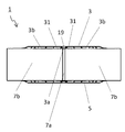
- the insert 1 of this embodiment has an upper surface 3, a lower surface 5, and a side surface 7, as shown in FIG.
- the upper surface 3 is a surface that at least partially functions as a rake surface.
- the upper surface 3 has a substantially polygonal shape and has at least one corner 3a and a plurality of sides 3b.
- the upper surface 3 is substantially rectangular and has four corners and four sides. The four corners are constituted by two acute corners and two obtuse corners. In FIG. 1 to FIG. 4, two acute corners are “corner 3a”, and a side extending from this corner 3a is “side 3b”.
- angular part 3a in the upper surface 3 in this embodiment is not a strict angle
- the side 3b on the upper surface 3 is not strictly limited to a linear shape, and may have a curved region.
- the lower surface 5 is a surface located on the opposite side to the upper surface 3, and functions as a seating surface for the pocket when the insert 1 of this embodiment is attached to the holder.
- the lower surface 5 in the present embodiment has a substantially polygonal shape, specifically a substantially rectangular shape, like the upper surface 3.
- the lower surface 5 in the present embodiment has the same shape as the upper surface 3, and the upper surface 3 and the lower surface 5 overlap each other when viewed from above. Therefore, as shown in FIGS. 3 and 4, the side surface 7 is orthogonal to the upper surface 3 and the lower surface 5.
- the lower surface 5 may be configured to be slightly smaller than the upper surface 3.
- the lower surface 5 is configured to be similar to the upper surface 3, and the side surface 7 is inclined toward a central axis O ⁇ b> 1 described later as the distance from the upper surface 3 increases.
- the shapes of the upper surface 3 and the lower surface 5 are not limited to the above forms.
- the shape of the upper surface 3 when viewed from the upper surface is substantially rectangular.
- the shape of the upper surface 3 when viewed from the upper surface is a polygonal shape such as a triangle, pentagon, or hexagon. May be.
- the shape of the upper surface 3 is a quadrangle, the shape of the upper surface 3 may be a rectangle, a parallelogram, a rhombus, or a square.
- the side surface 7 is a surface that at least partially functions as a flank surface. It is a surface adjacent to the upper surface 3. As shown in FIGS. 3 and 4, the side surface 7 in the present embodiment is located between the upper surface 3 and the lower surface 5, and is connected to the upper surface 3 and the lower surface 5, respectively.
- the side part 3 b corresponds to the ridge part of the upper surface 3 and the side surface 7.
- the side surface 7 of the insert 1 shown in FIG. 1 has four flat regions 7b and four curved regions 7a located between the flat regions (below the corner 3a). Yes.
- Examples of the material of the insert 1 include cemented carbide or cermet.
- Examples of the composition of the cemented carbide include WC—Co, WC—TiC—Co, and WC—TiC—TaC—Co.
- WC—Co is produced by adding cobalt (Co) powder to tungsten carbide (WC) and sintering.
- WC—TiC—Co is obtained by adding titanium carbide (TiC) to WC—Co.
- WC—TiC—TaC—Co is obtained by adding tantalum carbide (TaC) to WC—TiC—Co.
- cermet is a sintered composite material in which a metal is combined with a ceramic component.
- examples of the cermet include those containing a titanium compound such as titanium carbide (TiC) or titanium nitride (TiN) as a main component.
- the surface of the insert 1 may be coated with a film using a chemical vapor deposition (CVD) method or a physical vapor deposition (PVD) method.
- CVD chemical vapor deposition
- PVD physical vapor deposition
- the composition of the coating include titanium carbide (TiC), titanium nitride (TiN), titanium carbonitride (TiCN), and alumina (Al 2 O 3 ).
- the insert 1 has a through hole 9.
- the through hole 9 penetrates from the center of the upper surface 3 to the center of the lower surface 5.
- the through hole 9 is provided to fix the insert 1 to the holder of the cutting tool.
- the through-hole 9 is provided to insert a screw when the insert 1 is fixed to the holder of the cutting tool with a screw.
- the method for fixing the insert 1 to the holder is not limited to the above-described screw fixing.
- the through hole 9 is also used when the insert 1 is fixed to the holder with a clamper or a lever. In this case, the through hole 9 may not penetrate to the lower surface 9.
- the central axis O1 of the through hole 9 coincides with an imaginary straight line passing through the center of the upper surface 3 and the center of the lower surface 5. Further, the direction of the central axis O ⁇ b> 1 of the through hole 9, in other words, the through direction of the through hole 9 is orthogonal to the upper surface 3 and the lower surface 5.
- the through hole 9 is not limited to a configuration that is located from the center of the upper surface 3 to the center of the lower surface 5.
- the through hole 9 may be located between the flat regions 7 b located on the side surface 7 facing each other.
- the maximum width of the upper surface 3 when viewed from above is, for example, 6 to 25 mm.
- the maximum width of the upper surface 3 in the top view is the distance between the corner portions 3a according to FIG.
- the height from the lower surface 5 to the upper surface 3 is, for example, 1 to 10 mm.
- the height from the lower surface 5 to the upper surface 3 means a length in a direction parallel to the central axis O ⁇ b> 1 between the upper end of the upper surface 3 and the lower end of the lower surface 5.
- At least a part of the ridge portion where the upper surface 3 and the side surface 7 intersect is used as a cutting edge 31 for cutting the work material. That is, the cutting edge 31 is at least a part of the corner 3a and the side 3b connected to the corner 3a. Note that the entire side 3 b may be used as the cutting edge 31.
- the cutting edge 31, that is, the ridge where the upper surface 3 and the side surface 7 intersect with each other does not have to be sharply pointed.
- the cutting edge 31 is sharply sharpened, the machinability is increased.
- the cutting edge 31 (the ridge where the upper surface 3 and the side surface 7 intersect) may be slightly curved.
- the durability of the cutting blade 31 is enhanced.
- what is necessary is just to give the known honing process to the arrangement
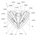
- the upper surface 3 in the present embodiment has a corner region 10 extending from the corner 3 a toward the center of the upper surface.
- the central portion may be regarded as the central axis O1, for example.
- the corner region 10 has a first corner surface 11, a second corner surface 12, a third corner surface 13 and a fourth corner surface 14 in this order from the corner 3a side.
- FIG. 8 is a cross-sectional view taken along line C1-C1 in FIG. 8 is a cross section including the bisector of the corner 3a and the central axis O1 of the through hole 9.
- the first corner surface 11 is a surface that is inclined downward as the distance from the corner 3a increases.
- the first corner surface 11 is shown in a straight line shape in the C1-C1 cross section.
- the first corner surface 11 has a shape curved in a concave shape in a cross section perpendicular to the bisector of the corner 3a.
- the first corner surface 11 functions as a rake face through which chips flow during cutting.
- the second corner surface 12 is located closer to the center than the first corner surface 11 and is a surface that is inclined upward as the distance from the first corner surface 11 increases.
- the second corner surface 12 mainly functions as a surface for curling chips.
- the second corner surface 12 is a flat surface. That is, the second corner surface 12 is shown in a straight line shape in the C1-C1 cross section, and is also shown in a straight line shape in a cross section perpendicular to the bisector of the corner 3a.
- the second corner surface 12 does not necessarily have to be continuous with the first corner surface 11. That is, another surface may be located between the first corner surface 11 and the second corner surface 12. For example, a flat surface region parallel to the lower surface 5 may be located between the first corner surface 11 and the second corner surface 12.
- the third corner surface 13 is located closer to the center than the second corner surface 12, and is a surface that is inclined upward as the distance from the second corner surface 12 increases. In the present embodiment, the third corner surface 13 is for securing a space between the second corner surface 12 and the fourth corner surface 14. In the present embodiment, the third corner surface 13 is a flat surface. That is, the third corner surface 13 is shown in a straight line shape in the C1-C1 cross section, and is also shown in a straight line shape in a cross section perpendicular to the bisector of the corner 3a.
- the third corner surface 13 does not necessarily have to be continuous with the second corner surface 12. That is, another surface may be located between the second corner surface 12 and the third corner surface 13. For example, a curved region connecting two surfaces may be located between the second corner surface 12 and the third corner surface 13.
- the fourth corner surface 14 is located closer to the center than the third corner surface 13 and is a surface that is inclined upward as the distance from the third corner surface 13 increases.
- the fourth corner surface 14 also functions mainly as a surface for curling chips.
- the fourth corner surface 14 is a flat surface. That is, the fourth corner surface 14 is shown in a straight line shape in the C1-C1 cross section, and is also shown in a straight line shape in a cross section orthogonal to the bisector of the corner 3a.
- the fourth corner surface 14 does not necessarily have to be continuous with the third corner surface 13. That is, another surface may be located between the third corner surface 13 and the fourth corner surface 14. For example, a curved region connecting two surfaces may be located between the third corner surface 13 and the fourth corner surface 14.
- the “flat surface” in the above does not have to be a strictly flat surface shape.
- the “flat surface” in the above may be a surface shape indicated by a gentle curve having a curvature radius of 5 mm or more in a cross section orthogonal to the corner 3a as shown in FIG.
- a surface shape having an arithmetic average surface roughness of about 5 ⁇ m may be used.
- the inclination angle (first inclination angle) ⁇ 11 of the first corner surface 11, the inclination angle (second inclination angle) ⁇ 12 of the second corner surface 12, and the inclination angle (third inclination angle) of the third corner surface 13 are shown.
- ⁇ 13 and the inclination angle (fourth inclination angle) ⁇ 14 of the fourth corner surface 14 are shown.
- the second inclination angle ⁇ 12 is larger than the third inclination angle ⁇ 13
- the fourth inclination angle ⁇ 14 is larger than the second inclination angle ⁇ 12.
- the fourth inclination angle ⁇ 14 is larger than the third inclination angle ⁇ 13 as well as the second inclination angle ⁇ 12.
- the angle between the corner surfaces 11, 12, 13, and 14 is an angle formed by a virtual plane parallel to this plane.
- an angle formed with a virtual plane parallel to the lower surface 5 can be set as an inclination angle.
- the virtual plane is shown as a reference line S.
- a reference line S may be a line orthogonal to an imaginary straight line passing through the center of the upper surface 3 and the center of the lower surface 5 (the central axis O1 of the through hole 9).
- the chip In the cutting process in which the cutting amount is small and the feeding amount is small as in the case where only the corner 3a of the upper surface 3 is used as the cutting blade 31, the chip has a narrow width and a thin shape.
- the shaped chips are generally easily deformed and unstable.
- the chips pass through the first corner surface 11 functioning as a rake face and travel toward the second corner surface 12.
- the second inclination angle ⁇ 12 of the second corner surface 12 closer to the corner portion 3a than the third corner surface 13 is larger than the third inclination angle ⁇ 13 of the third corner surface 13. Therefore, it is possible to stably curl the chips that are easily deformed and become unstable on the second corner surface 12.
- the insert 1 has excellent durability.
- the fourth inclination angle ⁇ 14 is larger than the second inclination angle ⁇ 12 and the third inclination angle ⁇ 13. From this, it is possible to reduce the possibility that the chips get over the fourth corner surface 14 under the cutting conditions where the cutting amount is small and the feeding amount is large, and the chips can be curled stably on the fourth corner surface 14. .
- the curl diameter of chips curled by the fourth corner surface 14 tends to be large.
- the third corner surface 13 having an inclination angle smaller than the second inclination angle ⁇ 12 and the fourth inclination angle ⁇ 14 is located between the second corner surface 12 and the fourth corner surface 14. Therefore, a wide space between the corner 3a and the fourth corner surface 14 can be secured. As a result, clogging of chips can be reduced and the chips can be curled stably.
- the second inclination angle ⁇ 12 of the second corner surface 12 is smaller than the fourth inclination angle ⁇ 14 of the fourth corner surface 14, even if the chips are in contact with the second corner surface 12, the feed amount When the cutting process is large, the second corner surface 12 is hardly curled. Chips having a large curl diameter are unlikely to be generated on the second corner surface 12 close to the corner 3a, and therefore clogging of chips is unlikely to occur.
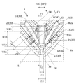
- the dimension L (the length of each corner surface) of each corner surface in the direction along the bisector of the corner 3a in the top view may be set as follows. .
- the dimension L11 of the first corner surface 11 is 0.2 to 0.35 mm
- the dimension L12 of the second corner surface 12 is 0.2 to 0.3 mm
- the dimension L13 of the third corner surface 13 is. Is 0.8 to 1.1 mm
- the dimension L14 of the fourth corner surface 14 is 0.2 to 0.4 mm.
- the dimension L13 of the third corner surface 13 may be larger than the dimensions L11, L12, and L14 of the other corner surfaces. In such a case, a wide space between the corner 3a and the fourth corner surface 14 can be secured. As a result, clogging of chips can be reduced and the chips can be curled stably.
- the dimension W (width of each corner surface) of each corner surface in the direction perpendicular to the bisector of the corner 3a on the upper surface may be set as follows.
- the dimension W11 of the first corner surface 11 is 0.2 to 0.35 mm
- the dimension W12 of the second corner surface 12 is 0.2 to 0.5 mm
- the dimension W13 of the third corner surface 13 is. Is 0.3 to 0.7 mm
- the dimension W14 of the fourth corner surface 14 is 0.3 to 0.6 mm.
- the dimension W12 of the second corner surface 12 may be larger than the dimensions W11, W13, and W14 of the other corner surfaces.
- each dimension of the corner surface W in each direction orthogonal to the bisector of the corner 3a may be the dimension W.
- the dimension W12 of the second corner surface 12 in the direction orthogonal to the bisector of the corner 3a is the largest on the corner 3a side and the smallest on the center side.
- the dimension W13 of the third corner surface 13 increases toward the center of the upper surface 3, and the dimension W14 of the fourth corner surface 14 increases as the distance from the third corner surface 13 increases. May decrease. In such a case, it is possible to reduce the possibility that the fourth corner surface 14 having a relatively high height from the lower surface 5 is too close to the side portion 3b and the generated chips ride on. Therefore, the chips can be curled stably by the corner region 10 and the side region 20.
- the upper surface 3 in the present embodiment may have a side region 20 located along the side 3b as shown in FIGS.
- the side region 20 has a first surface 21, a second surface 22, a third surface 23, and a fourth surface 24 in order from the side 3b.
- the first surface 21 extends toward the first corner surface 11.
- the second surface 22 extends toward the second corner surface 12.
- the fourth surface 24 extends toward the fourth corner surface 14.
- the third surface 23 is located between the second surface 22 and the fourth surface 24.
- the side region 20 may be located on both sides of the corner region 10. That is, the upper surface 3 may have a pair of side regions 20.
- the side region 20, that is, the region constituted by the first surface 21, the second surface 22, the third surface 23, and the fourth surface 24 is directed from the side 3 b toward the center of the upper surface 3. positioned.
- the first surface 21 is a surface that is inclined downward as the distance from the side 3b increases. In the present embodiment, the first surface 21 functions as a rake surface through which chips flow during cutting.
- the second surface 22 is located closer to the center than the first surface 21, and is a surface that is inclined upward from the side 3b, in other words, away from the first surface 21.
- the second surface 22 mainly functions as a surface for curling chips.
- the second surface 22 is a flat surface. That is, the second surface 22 is shown in a straight line shape in a cross section orthogonal to the side part 3b, and is also shown in a straight line shape in a cross section parallel to the side part 3b.
- the second surface 22 does not necessarily have to be continuous with the first surface 21. That is, another surface may be located between the first surface 21 and the second surface 22.
- a flat surface region may be located between the first surface 21 and the second surface 22. According to such a structure, it can reduce that a chip advances vigorously and contacts the 2nd surface 22 strongly.
- the third surface 23 is a flat surface located closer to the center than the second surface 22.
- the third surface 23 is for securing a space between the second surface 22 and the fourth surface 24.
- 10 and 11 show the inclination angle (seventh inclination angle) ⁇ 23 of the third surface 23.
- the third surface 23 is not necessarily inclined with respect to the reference line S, and may be parallel to the reference line S (virtual plane). That is, the seventh inclination angle ⁇ 23 may be 0 °.
- the third surface 23 does not necessarily have to be continuous with the second surface 22. That is, another surface may be located between the second surface 22 and the third surface 23. For example, a curved surface region that connects two surfaces may be located between the second surface 22 and the third surface 23.
- the fourth surface 24 is located closer to the center than the third surface 23, and is a surface inclined upward from the side 3b, in other words, away from the third surface 23.
- the fourth surface 24 mainly functions as a surface for curling chips.
- the fourth surface 24 is a flat surface. That is, the fourth surface 24 is shown in a straight line shape in a cross section orthogonal to the side part 3b, and is also shown in a straight line shape in a cross section parallel to the side part 3b.
- the fourth surface 24 does not necessarily have to be continuous with the third surface 23. That is, another surface may be located between the third surface 23 and the fourth surface 24. For example, a curved surface region that connects two surfaces may be located between the third surface 23 and the fourth surface 24.
- the sixth inclination angle ⁇ 22 is larger than the seventh inclination angle ⁇ 23.
- the eighth inclination angle ⁇ 24 is larger than the sixth inclination angle ⁇ 22.
- FIG. 9 is a cross section that includes the first surface 21 and the second surface 22 as shown in FIG. 7 and is orthogonal to the side 3b.
- FIG. 10 is a cross section that includes the first surface 21, the second surface 22, and the third surface 23 as shown in FIG. 7, and is orthogonal to the side 3b.
- FIG. 11 is a cross section that includes the first surface 21, the second surface 22, the third surface 23, and the fourth surface 24 as shown in FIG. 7, and is orthogonal to the side portion 3b.
- 9 to 11 are cross sections parallel to each other.
- the chips are wide and thin.
- the shaped chips are generally easily deformed and unstable.
- the chips pass through the first surface 21 toward the second surface 22.
- the sixth inclination angle ⁇ 22 of the second surface 22 closer to the side portion 3b than the third surface 23 may be larger than the seventh inclination angle ⁇ 23 of the third surface 23.
- the second surface 22 is a flat surface, chips can be stably brought into contact with the second surface 22 in the above-described cutting process.
- the eighth inclination angle ⁇ 24 may be larger than the sixth inclination angle ⁇ 22 and the seventh inclination angle ⁇ 23.
- the fourth surface 24 is a flat surface, chips can be stably brought into contact with the fourth surface 24 in the above-described cutting process.
- the curl diameter of chips curled by the fourth surface 24 tends to be large.
- the third surface 23 whose inclination angle is smaller than the sixth inclination angle ⁇ 22 and the eighth inclination angle ⁇ 24 is located between the second surface 22 and the fourth surface 24. Therefore, a wide space between the side 3b and the fourth surface 24 can be secured. As a result, clogging of chips can be reduced and the chips can be curled stably.
- the second surface 22 is hardly curled.
- chips having a large curl diameter are unlikely to be generated on the second surface 22 close to the side 3b, clogging of chips is difficult to occur.
- the insert 1 of the present embodiment has the side region 20, even when the cutting amount is large, the insert 1 can be satisfactorily applied both in cutting with a small feed amount and cutting with a large feed amount. Cutting material can be cut. Moreover, in the insert 1 of this embodiment, when the said side part area
- the dimension W (width of each surface) of each surface in the direction orthogonal to the side portion 3b in the top view may be set as follows.
- the dimension W21 of the first surface 21 is 0.2 to 0.4 mm
- the dimension W22 of the second surface 22 is 0.2 to 0.3 mm
- the dimension W23 of the third surface 23 is 0.
- the dimension W24 of the fourth surface 24 is 0.1 to 0.3 mm.
- the dimension W of each corner surface is the maximum of the dimensions of each surface in the direction orthogonal to the side 3b.
- the value may be the dimension W.
- the upper end of the second corner surface 12 may be positioned below the upper end of the second surface 22. According to such a configuration, when the cut amount is small and the feed amount is large, the chips are less likely to contact the second corner surface 12 and can be stably brought into contact with the second surface 22. Therefore, when the cut amount is small and the feed amount is large, the chips can flow stably to the third corner surface 13 and the fourth corner surface 14.
- the upper end of the second corner surface 12 is the most in the direction parallel to the virtual straight line (center axis O1 of the through hole 9) passing through the center of the upper surface 3 and the center of the lower surface 5 of the second corner surface 12. It is a part located away from the lower surface 5.
- the upper end of the second surface 22 is the lowermost surface 5 in the direction parallel to an imaginary straight line (center axis O1 of the through hole 9) passing through the center of the upper surface 3 and the center of the lower surface 5 of the second surface 22. It is the part which is located away from.
- the second corner surface 12 and the second surface 22 are both inclined surfaces that are inclined upward toward the center. Therefore, the upper end of the second corner surface 12 and the upper end of the second surface 22 can be rephrased as the inner peripheral end of the second corner surface 12 and the inner peripheral end of the second surface 22, respectively.
- the upper end of the third corner surface 13 may be located above the upper end of the third surface 23. According to such a configuration, it is possible to secure a space where a separate surface can be provided between the third corner surface 13 and the third surface 23. Therefore, the chips that can be provided separately can stably curl chips generated when the cutting amount is medium and the feeding amount is medium.
- the upper end of the third corner surface 13 and the upper end of the third surface 23 can be defined in the same manner as the upper end of the second corner surface 12 and the upper end of the second surface 22 described above.
- the third surface 23 is located inside the side portion 3 b of the upper surface 3, while the third corner surface 13 is located inside the corner portion 3 a of the upper surface 3. Therefore, for example, when the cut amount and the feed amount are large, the portion where the third corner surface 13 is located is likely to be subjected to a larger load than the portion where the third surface 23 is located.
- the third inclination angle ⁇ 13 of the third corner surface 13 may be larger than the seventh inclination angle ⁇ 23 of the third surface 23.
- the strength of the portion where the third corner surface 13 is located can be higher than that of the portion where the third surface 23 is located. Therefore, it can be set as insert 1 with sufficient durability.
- the second inclination angle ⁇ 12 of the second corner surface 12 may be larger than the sixth inclination angle ⁇ 22 of the second surface 22.
- the first inclination angle ⁇ 21 of the first surface 21, the second inclination angle ⁇ 22 of the second surface 22, and the seventh inclination angle ⁇ 23 of the fourth surface 24 are constant along the side 3b. May be. In such a case, the curl action of chips can be stabilized regardless of the amount of cut.
- the difference between the second inclination angle ⁇ 12 of the second corner surface 12 and the fourth inclination angle ⁇ 14 of the fourth corner surface 14 is the sixth inclination angle ⁇ 22 of the second surface 22 and the eighth inclination angle of the fourth surface 24. It may be smaller than the difference of ⁇ 24.
- the inclination angle ⁇ 12 of the second corner surface 12 may be larger than the inclination angle ⁇ 22 of the second surface 22.
- the length L12 of the second corner surface 12 is relatively short, and the length L13 of the third corner surface 3 is easily secured. Therefore, when the cut amount is small and the feed amount is large, the chips are easily guided smoothly to the third corner surface 13.
- the inclination angle ⁇ 13 of the third corner surface 13 is larger than the inclination angle ⁇ 23 of the third surface 23, and smaller than the inclination angle ⁇ 22 of the second surface 22 and the inclination angle ⁇ 24 of the fourth surface 24. Good. When such a relationship is satisfied, the curling action of the chips is enhanced under cutting conditions in which the cutting amount is medium and the feeding amount is medium.
- the shape of the lower surface 5 and the shape of the upper surface 3 are the same, and the cutting blade may be located at least at a part where the lower surface 5 and the side surface 7 intersect. .
- the insert 1 can be used for cutting with the upper surface 3 and the lower surface 5 of the insert 1 reversed.
- the height of the upper end of the fourth corner surface 14 is the same as the height of the upper end of the fourth surface 24. Therefore, the upper surface 3 can function stably as a seating surface for the pocket.
- the height of the upper end of the fourth corner surface 14 is the same as the height of the upper end of the fourth surface 24.
- the heights of both need not be exactly the same, for example, a deviation of about 2%. There may be.
- the height of the upper end of the fourth corner surface 14 is 1, the height of the upper end of the fourth surface 24 may be about 0.98 to 1.02.
- the upper end of the fourth corner surface 14 and the upper end of the fourth surface 24 can be defined similarly to the upper end of the second corner surface 12 and the upper end of the second surface 22 described above.
- the height of the upper end of the fourth corner surface 14 is from the lower surface 5 to the fourth corner surface 14 in a direction parallel to an imaginary straight line passing through the center of the upper surface 3 and the center of the lower surface 5 (the central axis O1 of the through hole 9). It is a dimension to the upper end of.
- the height of the upper end of the fourth surface 24 is from the lower surface 5 to the fourth surface 24 in a direction parallel to an imaginary straight line passing through the center of the upper surface 3 and the center of the lower surface 5 (the central axis O1 of the through hole 9). It is a dimension to the upper end.
- the chip width becomes narrow, and therefore the behavior of the chips tends to become more unstable.
- the width of the third corner surface 13 may increase as the distance from the corner 3a increases. According to such a configuration, in the cutting process in which the cutting amount is medium and the feeding amount is medium, the region located on the side of the third corner surface 13 having the curl function is closer to the side 3b. . Therefore, the chips generated in the cutting process can be stably brought into contact with the third corner surface 13, and the curling action of the chips is enhanced.
- the width of the third corner surface 13 (the dimension W of the third corner surface 13) becomes wider as the distance from the corner 3a increases.
- the width (the dimension W of the fourth corner surface 14) may become narrower as the distance from the corner 3a increases. According to such a configuration, it is possible to ensure the width in the direction along the side 3 b in the fourth surface 24 adjacent to the fourth corner surface 14. Therefore, it is possible to stably curl chips on the fourth surface 24 in a cutting process with a large cut amount and a large feed amount.
- the side region 20 may further have a fifth surface 25.
- the fifth surface 25 is located between the third corner surface 13 and the fourth corner surface 14, and the third surface 23 and the fourth surface 24. At the same time, it is inclined downward as the distance from the third corner surface 13 and the fourth corner surface 14 increases. In the case of having the fifth surface 25 as described above, the effect of stably curling the chips is enhanced regardless of the amount of cutting.
- the cutting edge 31 may be linear in a side view. At this time, the height from the lower surface 5 of the cutting blade 31 may be constant.
- the third surface 23 may be parallel to the lower surface 5, or may be inclined downward as the distance from the cutting edge 31 increases. It may be a convex curve. In any case, a space where chips flow between the second surface 22 and the fourth surface 24 can be secured, and chip clogging can be reduced.
- the upper surface 3 may further have a land portion positioned along the cutting edge 31. That is, you may further have the land part located along the corner
- the insert 1 of one embodiment was demonstrated using drawing, the insert of this indication is not limited to the composition of the above-mentioned embodiment, and is the range which does not deviate from the gist of this indication, Modifications not described in detail are also included.
- the first corner surface 11 is a concave curved surface
- the second corner surface 12, the third corner surface 13 and the fourth corner surface 14 are flat surfaces.
- the insert is not limited to this. That is, the shape of each corner surface in the insert of the present disclosure may be any shape as long as the inclination angle of each corner surface constituting the corner portion region 10 satisfies the relationship described above.
- the shape of each surface constituting the side region 20 is the same.
- the cutting tool 101 of the present embodiment includes a holder 105 having a pocket 103 on the tip 105a side and the insert 1 positioned in the pocket 103 as shown in FIG.
- the insert 1 is mounted so that a portion used as the cutting edge 31 in the ridge portion protrudes from the tip of the holder 105.
- the holder 105 is an elongated rod-like body.
- One pocket 103 is provided on the front end 105 a side of the holder 105.
- the pocket 103 is a part to which an insert is attached, and is open to the front end surface of the holder 105. At this time, since the pocket 103 is also open to the side surface of the holder 105, the insert can be easily attached.
- the pocket 103 has a seating surface parallel to the lower surface (not shown) of the holder 105 and a constraining side surface inclined with respect to the seating surface.
- the insert 1 is located in the pocket 103. At this time, the lower surface of the insert 1 may be in direct contact with the pocket 103, or a sheet may be sandwiched between the insert 1 and the pocket 103.
- the insert 1 is mounted so that a portion used as the cutting edge 31 in the ridge portion protrudes outward from the holder 105.
- the insert 1 is attached to the holder 105 with a fixing screw 107. That is, the fixing screw 107 is inserted into the through hole of the insert 1, and the tip of the fixing screw 107 is inserted into a screw hole (not shown) formed in the insert pocket 103 to screw the screw portions together. As a result, the insert 1 is mounted on the holder 105.
- the material of the holder 105 for example, steel or cast iron can be used. Further, as the material of the holder 105, steel having high toughness among these members may be used.
- a cutting tool used for so-called turning is illustrated.
- the turning process include an inner diameter process, an outer diameter process, and a grooving process.
- the cutting tool is not limited to that used for turning. For example, you may use the insert of said embodiment for the cutting tool used for a turning process.
- the cut workpiece is produced by cutting the work material 201.
- the method for manufacturing a cut product according to the present embodiment includes the following steps (1) to (4). (1) A step of rotating the prepared work material 201 (see FIG. 13). (2) A step of moving the cutting tool 101 in the X1 direction toward the rotating work material 201 to bring the cutting tool 101 closer to the work material 201 (see FIG. 13). (3) By bringing the cutting tool 101 closer to the work material 201, the cutting edge 31 of the cutting tool 101 is brought into contact with a desired position on the surface of the rotating work material 201, and the surface of the work material 201. The process of processing (refer FIG. 14). (4) A step of separating the cutting tool 101 from the work material 201 in the X2 direction (see FIG. 15).
- Examples of the material of the work material 201 prepared in the step (1) include aluminum, carbon steel, alloy steel, stainless steel, cast iron, and non-ferrous metal.
- the step (2) can be performed, for example, by bringing the work material 201 close to the work material 201 in a state where the work material 201 is rotated around the axis O2.
- the work material 201 and the drill 101 may be relatively close to each other, and the work material 201 may be close to the drill 101.
- the step (2) can be performed, for example, by bringing the cutting tool 101 relatively close to the work material 201 in a state where the work material 201 is rotated around the axis O2.
- the work material 201 and the cutting tool 101 may be relatively close to each other, and the work material 201 may be close to the cutting tool 101.
- the work material 201 and the cutting tool 101 may be relatively separated from each other.
- the work material 201 may be separated from the cutting tool 101. .
- a cut product can be obtained through the above steps.
- the cutting tool 101 since the cutting tool 101 is used, even when the cutting amount is small, the cutting is good even under cutting conditions where the feed amount is small or large. It can be performed. As a result, it is possible to obtain a cut product with high processing surface accuracy.
- the cutting tool 101 is cut at different locations on the work material 201 while keeping the work material 201 rotated. What is necessary is just to repeat the process which makes a blade contact.
- the present disclosure is not limited to the above-described embodiment, and it is needless to say that the embodiment can be arbitrarily set without departing from the gist of the present disclosure.
Landscapes
- Engineering & Computer Science (AREA)
- Mechanical Engineering (AREA)
- Cutting Tools, Boring Holders, And Turrets (AREA)
Abstract
Priority Applications (3)
| Application Number | Priority Date | Filing Date | Title |
|---|---|---|---|
| DE112017000671.6T DE112017000671B4 (de) | 2016-02-05 | 2017-02-06 | Einsatz, Schneidwerkzeug und Verfahren des Herstellens eines maschinell-bearbeiteten Produkts |
| JP2017565681A JP6612900B2 (ja) | 2016-02-05 | 2017-02-06 | インサート、切削工具及び切削加工物の製造方法 |
| US16/075,188 US10583501B2 (en) | 2016-02-05 | 2017-02-06 | Insert, cutting tool, and method for manufacturing cutting workpiece |
Applications Claiming Priority (2)
| Application Number | Priority Date | Filing Date | Title |
|---|---|---|---|
| JP2016-020429 | 2016-02-05 | ||
| JP2016020429 | 2016-02-05 |
Publications (1)
| Publication Number | Publication Date |
|---|---|
| WO2017135469A1 true WO2017135469A1 (fr) | 2017-08-10 |
Family
ID=59499737
Family Applications (1)
| Application Number | Title | Priority Date | Filing Date |
|---|---|---|---|
| PCT/JP2017/004224 Ceased WO2017135469A1 (fr) | 2016-02-05 | 2017-02-06 | Plaquette, outil de coupe et procédé de fabrication d'une pièce de coupe |
Country Status (4)
| Country | Link |
|---|---|
| US (1) | US10583501B2 (fr) |
| JP (1) | JP6612900B2 (fr) |
| DE (1) | DE112017000671B4 (fr) |
| WO (1) | WO2017135469A1 (fr) |
Cited By (6)
| Publication number | Priority date | Publication date | Assignee | Title |
|---|---|---|---|---|
| JPWO2021117872A1 (fr) * | 2019-12-11 | 2021-06-17 | ||
| CN114025902A (zh) * | 2019-07-08 | 2022-02-08 | 京瓷株式会社 | 切削刀片、切削刀具以及切削加工物的制造方法 |
| EP3848137A4 (fr) * | 2018-09-06 | 2022-04-20 | Sumitomo Electric Hardmetal Corp. | Plaquette de coupe |
| CN114650892A (zh) * | 2019-11-13 | 2022-06-21 | 京瓷株式会社 | 切削刀片、切削工具以及切削加工物的制造方法 |
| JP7223305B1 (ja) | 2022-09-26 | 2023-02-16 | 株式会社タンガロイ | 切削インサート |
| WO2023084973A1 (fr) * | 2021-11-09 | 2023-05-19 | 京セラ株式会社 | Plaquette de coupe, outil de coupe, et procédé de fabrication de pièce coupée |
Families Citing this family (3)
| Publication number | Priority date | Publication date | Assignee | Title |
|---|---|---|---|---|
| DE112017003869B4 (de) * | 2016-08-03 | 2024-05-29 | Kyocera Corporation | Schneideinsatz, Schneidwerkzeug und Verfahren des Herstellens eines maschinell-bearbeiteten Produkts |
| KR102262037B1 (ko) * | 2019-12-27 | 2021-06-08 | 한국야금 주식회사 | 절삭 인서트 및 이를 장착한 절삭공구 |
| US12337391B2 (en) * | 2020-05-26 | 2025-06-24 | Kyocera Corporation | Cutting insert, cutting tool, and method for manufacturing machined product |
Citations (9)
| Publication number | Priority date | Publication date | Assignee | Title |
|---|---|---|---|---|
| JPS6120204U (ja) * | 1984-07-09 | 1986-02-05 | ダイジヱツト工業株式会社 | スロ−アウエイチツプ |
| JPS62127702U (fr) * | 1986-02-03 | 1987-08-13 | ||
| JPS6313601U (fr) * | 1986-07-11 | 1988-01-29 | ||
| JPH0160805U (fr) * | 1987-10-14 | 1989-04-18 | ||
| JP2004106150A (ja) * | 2002-09-20 | 2004-04-08 | Sumitomo Electric Ind Ltd | 刃先交換式チップ |
| JP2010149280A (ja) * | 2008-11-21 | 2010-07-08 | Kyocera Corp | 切削インサートおよび切削工具並びにそれを用いた切削方法 |
| JP2011115896A (ja) * | 2009-12-03 | 2011-06-16 | Mitsubishi Materials Corp | 切削インサート |
| JP5187447B2 (ja) * | 2009-09-25 | 2013-04-24 | 株式会社タンガロイ | 切削インサートおよび切削工具 |
| WO2014192798A1 (fr) * | 2013-05-28 | 2014-12-04 | 京セラ株式会社 | Plaquette de coupe et outil de coupe, ainsi que procédé permettant de produire des pièces coupées à l'aide d'un outil de coupe |
Family Cites Families (18)
| Publication number | Priority date | Publication date | Assignee | Title |
|---|---|---|---|---|
| US5193947A (en) | 1991-03-04 | 1993-03-16 | Gte Valenite Corporation | High depth, low force cutting insert |
| SE501913C2 (sv) * | 1993-10-21 | 1995-06-19 | Sandvik Ab | Skär för skärande verktyg |
| US5456557A (en) * | 1994-08-09 | 1995-10-10 | Valenite Inc. | Cutting insert |
| JP2002192407A (ja) * | 2000-12-26 | 2002-07-10 | Ngk Spark Plug Co Ltd | 切削工具 |
| SE523620C2 (sv) * | 2001-10-01 | 2004-05-04 | Sandvik Ab | Skär för spånavskiljande bearbetning med ytavstrykande eggsegment. |
| SE523617C2 (sv) * | 2001-10-01 | 2004-05-04 | Sandvik Ab | Skär för spånavskiljande bearbetning försedd med spånbrytande geometri |
| SE530153C2 (sv) * | 2005-02-22 | 2008-03-11 | Seco Tools Ab | Skär för svarvning med ett perifert land av konstant bredd |
| SE529146C2 (sv) * | 2005-02-22 | 2007-05-15 | Seco Tools Ab | Skär för svarvning där fasvinkeln vid hörnet uppvisar ett minimum |
| JP5158490B2 (ja) * | 2008-03-06 | 2013-03-06 | 住友電工ハードメタル株式会社 | 刃先交換式切削チップ |
| JP5515504B2 (ja) * | 2008-08-22 | 2014-06-11 | 三菱マテリアル株式会社 | 切削インサート |
| AT11676U1 (de) * | 2009-10-02 | 2011-03-15 | Ceratizit Austria Gmbh | Schneideinsatz für ein schneidwerkzeug |
| CA2774671A1 (fr) * | 2009-10-15 | 2011-04-21 | Tungaloy Corporation | Insert de coupe |
| JP5895456B2 (ja) * | 2010-11-15 | 2016-03-30 | 三菱マテリアル株式会社 | 切削インサート |
| US8967920B2 (en) * | 2011-09-13 | 2015-03-03 | Iscar, Ltd. | Cutting insert and chip-control arrangement therefor |
| SE536986C2 (sv) * | 2013-03-20 | 2014-11-25 | Sandvik Intellectual Property | Månghörnigt svarvskär med spånkontrollerande styrytor |
| SE1350348A1 (sv) * | 2013-03-20 | 2014-09-21 | Sandvik Intellectual Property | Dubbelsidigt, indexerbart svarvskär |
| JP6356781B2 (ja) * | 2014-02-26 | 2018-07-11 | 京セラ株式会社 | 切削インサート、切削工具及び切削加工物の製造方法 |
| KR20170047190A (ko) * | 2014-09-05 | 2017-05-04 | 스미또모 덴꼬오 하드메탈 가부시끼가이샤 | 스로어웨이 팁 |
-
2017
- 2017-02-06 JP JP2017565681A patent/JP6612900B2/ja active Active
- 2017-02-06 WO PCT/JP2017/004224 patent/WO2017135469A1/fr not_active Ceased
- 2017-02-06 DE DE112017000671.6T patent/DE112017000671B4/de active Active
- 2017-02-06 US US16/075,188 patent/US10583501B2/en active Active
Patent Citations (9)
| Publication number | Priority date | Publication date | Assignee | Title |
|---|---|---|---|---|
| JPS6120204U (ja) * | 1984-07-09 | 1986-02-05 | ダイジヱツト工業株式会社 | スロ−アウエイチツプ |
| JPS62127702U (fr) * | 1986-02-03 | 1987-08-13 | ||
| JPS6313601U (fr) * | 1986-07-11 | 1988-01-29 | ||
| JPH0160805U (fr) * | 1987-10-14 | 1989-04-18 | ||
| JP2004106150A (ja) * | 2002-09-20 | 2004-04-08 | Sumitomo Electric Ind Ltd | 刃先交換式チップ |
| JP2010149280A (ja) * | 2008-11-21 | 2010-07-08 | Kyocera Corp | 切削インサートおよび切削工具並びにそれを用いた切削方法 |
| JP5187447B2 (ja) * | 2009-09-25 | 2013-04-24 | 株式会社タンガロイ | 切削インサートおよび切削工具 |
| JP2011115896A (ja) * | 2009-12-03 | 2011-06-16 | Mitsubishi Materials Corp | 切削インサート |
| WO2014192798A1 (fr) * | 2013-05-28 | 2014-12-04 | 京セラ株式会社 | Plaquette de coupe et outil de coupe, ainsi que procédé permettant de produire des pièces coupées à l'aide d'un outil de coupe |
Cited By (15)
| Publication number | Priority date | Publication date | Assignee | Title |
|---|---|---|---|---|
| EP3848137A4 (fr) * | 2018-09-06 | 2022-04-20 | Sumitomo Electric Hardmetal Corp. | Plaquette de coupe |
| US11400521B2 (en) | 2018-09-06 | 2022-08-02 | Sumitomo Electric Hardmetal Corp. | Cutting insert |
| CN114025902A (zh) * | 2019-07-08 | 2022-02-08 | 京瓷株式会社 | 切削刀片、切削刀具以及切削加工物的制造方法 |
| CN114025902B (zh) * | 2019-07-08 | 2024-01-19 | 京瓷株式会社 | 切削刀片、切削刀具以及切削加工物的制造方法 |
| CN114650892A (zh) * | 2019-11-13 | 2022-06-21 | 京瓷株式会社 | 切削刀片、切削工具以及切削加工物的制造方法 |
| US20220379384A1 (en) * | 2019-11-13 | 2022-12-01 | Kyocera Corporation | Cutting insert, cutting tool, and method for manufacturing machined product |
| JP7295972B2 (ja) | 2019-12-11 | 2023-06-21 | 京セラ株式会社 | インサート、切削工具及び同切削工具を用いた被削材切削方法 |
| US12454011B2 (en) * | 2019-12-11 | 2025-10-28 | Kyocera Corporation | Insert, cutting tool, and method for cutting workpiece using the cutting tool |
| US20230056761A1 (en) * | 2019-12-11 | 2023-02-23 | Kyocera Corporation | Insert, cutting tool, and method for cutting workpiece using the cutting tool |
| JPWO2021117872A1 (fr) * | 2019-12-11 | 2021-06-17 | ||
| JPWO2023084973A1 (fr) * | 2021-11-09 | 2023-05-19 | ||
| WO2023084973A1 (fr) * | 2021-11-09 | 2023-05-19 | 京セラ株式会社 | Plaquette de coupe, outil de coupe, et procédé de fabrication de pièce coupée |
| JP7739448B2 (ja) | 2021-11-09 | 2025-09-16 | 京セラ株式会社 | 切削インサート、切削工具、及び切削加工物の製造方法 |
| JP2024047455A (ja) * | 2022-09-26 | 2024-04-05 | 株式会社タンガロイ | 切削インサート |
| JP7223305B1 (ja) | 2022-09-26 | 2023-02-16 | 株式会社タンガロイ | 切削インサート |
Also Published As
| Publication number | Publication date |
|---|---|
| US10583501B2 (en) | 2020-03-10 |
| DE112017000671T5 (de) | 2018-10-11 |
| JP6612900B2 (ja) | 2019-11-27 |
| US20190039152A1 (en) | 2019-02-07 |
| DE112017000671B4 (de) | 2024-01-04 |
| JPWO2017135469A1 (ja) | 2018-10-04 |
Similar Documents
| Publication | Publication Date | Title |
|---|---|---|
| JP6612900B2 (ja) | インサート、切削工具及び切削加工物の製造方法 | |
| JP5379870B2 (ja) | 切削インサートおよび切削工具、ならびにそれらを用いた被削材の切削方法 | |
| JP5844881B2 (ja) | 切削インサート、切削工具および切削加工物の製造方法 | |
| JP6356781B2 (ja) | 切削インサート、切削工具及び切削加工物の製造方法 | |
| WO2014192798A1 (fr) | Plaquette de coupe et outil de coupe, ainsi que procédé permettant de produire des pièces coupées à l'aide d'un outil de coupe | |
| JP6861269B2 (ja) | 切削インサート、切削工具及び切削加工物の製造方法 | |
| US11911828B2 (en) | Cutting insert, cutting tool, and method for manufacturing machined product | |
| US11701715B2 (en) | Cutting insert, cutting tool, and method for manufacturing machined product | |
| JPWO2018079491A1 (ja) | 切削インサート、切削工具及び切削加工物の製造方法 | |
| WO2018012463A1 (fr) | Plaquette de coupe, outil de coupe et procédé de production d'objet usiné | |
| WO2017217481A1 (fr) | Insert de coupe, outil de coupe et procédé de fabrication pour produit découpé | |
| US10576548B2 (en) | Insert, cutting tool, and method for manufacturing machined product | |
| WO2018159499A1 (fr) | Plaquette de coupe, outil de coupe et procédé de fabrication de pièce coupée | |
| JPWO2018021419A1 (ja) | 切削インサート、切削工具及び切削加工物の製造方法 | |
| JP7325510B2 (ja) | 切削インサート、切削工具及び切削加工物の製造方法 | |
| WO2019004030A1 (fr) | Insert de coupe, outil de coupe, et procédé de fabrication d'une pièce coupée | |
| JP2019171511A (ja) | 切削インサート、切削工具及び切削加工物の製造方法 | |
| JP5783922B2 (ja) | 切削インサート、切削工具および切削工具を用いた被削材の切削方法 | |
| JP5683208B2 (ja) | 切削インサートおよび切削工具ならびにそれを用いた被削材の切削方法 | |
| JPWO2018043373A1 (ja) | 切削インサート、切削工具及び切削加工物の製造方法 | |
| JPWO2018025723A1 (ja) | 切削インサート、切削工具及び切削加工物の製造方法 | |
| WO2021230219A1 (fr) | Insert de coupe, outil de coupe et procédé de fabrication de pièce coupée |
Legal Events
| Date | Code | Title | Description |
|---|---|---|---|
| 121 | Ep: the epo has been informed by wipo that ep was designated in this application |
Ref document number: 17747619 Country of ref document: EP Kind code of ref document: A1 |
|
| ENP | Entry into the national phase |
Ref document number: 2017565681 Country of ref document: JP Kind code of ref document: A |
|
| WWE | Wipo information: entry into national phase |
Ref document number: 112017000671 Country of ref document: DE |
|
| 122 | Ep: pct application non-entry in european phase |
Ref document number: 17747619 Country of ref document: EP Kind code of ref document: A1 |