WO2017138037A1 - Échangeur de chaleur du type à plaques - Google Patents
Échangeur de chaleur du type à plaques Download PDFInfo
- Publication number
- WO2017138037A1 WO2017138037A1 PCT/JP2016/000672 JP2016000672W WO2017138037A1 WO 2017138037 A1 WO2017138037 A1 WO 2017138037A1 JP 2016000672 W JP2016000672 W JP 2016000672W WO 2017138037 A1 WO2017138037 A1 WO 2017138037A1
- Authority
- WO
- WIPO (PCT)
- Prior art keywords
- heat exchange
- support
- heat
- plate
- moving support
- Prior art date
- Legal status (The legal status is an assumption and is not a legal conclusion. Google has not performed a legal analysis and makes no representation as to the accuracy of the status listed.)
- Ceased
Links
Images




Classifications
-
- F—MECHANICAL ENGINEERING; LIGHTING; HEATING; WEAPONS; BLASTING
- F28—HEAT EXCHANGE IN GENERAL
- F28F—DETAILS OF HEAT-EXCHANGE AND HEAT-TRANSFER APPARATUS, OF GENERAL APPLICATION
- F28F9/00—Casings; Header boxes; Auxiliary supports for elements; Auxiliary members within casings
- F28F9/007—Auxiliary supports for elements
- F28F9/0075—Supports for plates or plate assemblies
-
- F—MECHANICAL ENGINEERING; LIGHTING; HEATING; WEAPONS; BLASTING
- F28—HEAT EXCHANGE IN GENERAL
- F28D—HEAT-EXCHANGE APPARATUS, NOT PROVIDED FOR IN ANOTHER SUBCLASS, IN WHICH THE HEAT-EXCHANGE MEDIA DO NOT COME INTO DIRECT CONTACT
- F28D9/00—Heat-exchange apparatus having stationary plate-like or laminated conduit assemblies for both heat-exchange media, the media being in contact with different sides of a conduit wall
-
- F—MECHANICAL ENGINEERING; LIGHTING; HEATING; WEAPONS; BLASTING
- F28—HEAT EXCHANGE IN GENERAL
- F28D—HEAT-EXCHANGE APPARATUS, NOT PROVIDED FOR IN ANOTHER SUBCLASS, IN WHICH THE HEAT-EXCHANGE MEDIA DO NOT COME INTO DIRECT CONTACT
- F28D9/00—Heat-exchange apparatus having stationary plate-like or laminated conduit assemblies for both heat-exchange media, the media being in contact with different sides of a conduit wall
- F28D9/0093—Multi-circuit heat-exchangers, e.g. integrating different heat exchange sections in the same unit or heat-exchangers for more than two fluids
-
- F—MECHANICAL ENGINEERING; LIGHTING; HEATING; WEAPONS; BLASTING
- F28—HEAT EXCHANGE IN GENERAL
- F28F—DETAILS OF HEAT-EXCHANGE AND HEAT-TRANSFER APPARATUS, OF GENERAL APPLICATION
- F28F3/00—Plate-like or laminated elements; Assemblies of plate-like or laminated elements
- F28F3/08—Elements constructed for building-up into stacks, e.g. capable of being taken apart for cleaning
-
- F—MECHANICAL ENGINEERING; LIGHTING; HEATING; WEAPONS; BLASTING
- F28—HEAT EXCHANGE IN GENERAL
- F28F—DETAILS OF HEAT-EXCHANGE AND HEAT-TRANSFER APPARATUS, OF GENERAL APPLICATION
- F28F3/00—Plate-like or laminated elements; Assemblies of plate-like or laminated elements
- F28F3/08—Elements constructed for building-up into stacks, e.g. capable of being taken apart for cleaning
- F28F3/083—Elements constructed for building-up into stacks, e.g. capable of being taken apart for cleaning capable of being taken apart
-
- F—MECHANICAL ENGINEERING; LIGHTING; HEATING; WEAPONS; BLASTING
- F28—HEAT EXCHANGE IN GENERAL
- F28F—DETAILS OF HEAT-EXCHANGE AND HEAT-TRANSFER APPARATUS, OF GENERAL APPLICATION
- F28F9/00—Casings; Header boxes; Auxiliary supports for elements; Auxiliary members within casings
-
- F—MECHANICAL ENGINEERING; LIGHTING; HEATING; WEAPONS; BLASTING
- F28—HEAT EXCHANGE IN GENERAL
- F28F—DETAILS OF HEAT-EXCHANGE AND HEAT-TRANSFER APPARATUS, OF GENERAL APPLICATION
- F28F9/00—Casings; Header boxes; Auxiliary supports for elements; Auxiliary members within casings
- F28F9/007—Auxiliary supports for elements
-
- F—MECHANICAL ENGINEERING; LIGHTING; HEATING; WEAPONS; BLASTING
- F28—HEAT EXCHANGE IN GENERAL
- F28F—DETAILS OF HEAT-EXCHANGE AND HEAT-TRANSFER APPARATUS, OF GENERAL APPLICATION
- F28F2275/00—Fastening; Joining
- F28F2275/20—Fastening; Joining with threaded elements
- F28F2275/205—Fastening; Joining with threaded elements with of tie-rods
-
- F—MECHANICAL ENGINEERING; LIGHTING; HEATING; WEAPONS; BLASTING
- F28—HEAT EXCHANGE IN GENERAL
- F28F—DETAILS OF HEAT-EXCHANGE AND HEAT-TRANSFER APPARATUS, OF GENERAL APPLICATION
- F28F2280/00—Mounting arrangements; Arrangements for facilitating assembling or disassembling of heat exchanger parts
- F28F2280/02—Removable elements
-
- F—MECHANICAL ENGINEERING; LIGHTING; HEATING; WEAPONS; BLASTING
- F28—HEAT EXCHANGE IN GENERAL
- F28F—DETAILS OF HEAT-EXCHANGE AND HEAT-TRANSFER APPARATUS, OF GENERAL APPLICATION
- F28F2280/00—Mounting arrangements; Arrangements for facilitating assembling or disassembling of heat exchanger parts
- F28F2280/06—Adapter frames, e.g. for mounting heat exchanger cores on other structure and for allowing fluidic connections
Definitions
- the present invention relates to a plate heat exchanger.
- the plate heat exchanger has a fixed support and a moving support in the heat exchanging section, and the moving support is attached to be movable in the long axis direction of the guide bar.
- a thin heat transfer plate in which irregularities are formed by pressing is provided with a sealing gasket installed in a laminated form.
- the heat transfer plate and gasket attached to the plate heat exchanger may be removed for maintenance of the plate heat exchanger.
- the moving support is moved in the long axis direction of the guide bar, and the heat transfer plate is removed, for example, the heat transfer plate is inclined and the guide bar is removed from the guide groove formed in the heat transfer plate.
- the plate-type heat exchanger has a removal area that is an area for moving the moving support and removing the heat transfer frame when the heat transfer frame is removed. Since this removal area is always provided with a guide bar or the like, it is not used for other purposes during normal operation, and is used only during maintenance and inspections that are not so frequent. Thus, the removal area secured in the plate heat exchanger unnecessarily occupies the installation space for the plate heat exchanger during normal operation.
- Patent Document 1 a heat transfer plate between a fixed support and a movable support is provided, and a nut in which a bolt is screwed and fixed to both ends of a sleeve having a predetermined length and a nut in which a bolt is screwed through are provided.
- a plate-type heat exchanger that is fastened and fixed with a fastening bracket is disclosed. According to the plate-type heat exchanger of Patent Document 1, since the bolt does not protrude from the moving support, the removal region can be effectively used for other purposes during normal operation.
- multiple units typically two plate-type heat exchangers, are equipped with multiple heat exchangers, one serving as the main heat exchanger and the other serving as the secondary heat exchanger, which is always the main heat exchanger. It is preferable to perform heat exchange with a heat exchanger and switch to a sub heat exchanger to perform heat exchange when a problem occurs.
- two plate-type heat exchangers are simply arranged, the required number of removal areas are required, so that it is impossible to answer an application that requires space saving.
- an object of the present invention is to provide a heat exchanger that can suppress the space occupied by the removal region while including two plate-type heat exchangers.
- the present invention relates to a plate heat exchanger including a first heat exchanging part and a second heat exchanging part having a refrigerant flow path independent of the first heat exchanging part.
- the first heat exchanging portion in the present invention includes a first fixed support that supports a plurality of first heat transfer plates arranged adjacent to each other with their heat transfer surfaces facing each other from one end side in the direction of arrangement. And a first moving support that supports the plurality of first heat transfer plates at a first support position on one end side in the arrangement direction.
- the first heat exchanging unit moves the first moving support body from the first support position to a first retracted position that is separated from the first support position and between the first support position and the first retracted position.
- the second heat exchanging portion in the present invention includes a second fixed support that supports a plurality of second heat transfer plates arranged adjacent to each other with their heat transfer surfaces facing each other from one end side in the direction of arrangement. And a second moving support that supports the plurality of second heat transfer plates at a second support position on one end side in the arrangement direction.
- the second heat exchanging unit moves the second moving support body from the second support position to the second retracted position separated in the direction of the array, and moves the second moving support body between the second support position and the second retracted position.
- a removal area is formed and the second heat transfer plate is removed from the second removal area.
- the plate type heat exchanger of this invention is characterized by sharing the 1st removal area
- the first heat exchange unit and the second heat exchange unit are configured such that the first movement support of the first heat exchange unit and the second movement support of the second heat exchange unit face each other. It is preferable that they are arranged.
- the dimension in the direction of the arrangement of the first removal region of the first heat exchange part is equal to the dimension in the direction of the arrangement of the second removal region of the second heat exchange part. Is preferred.
- the plate heat exchanger of the present invention includes a common guide that is supported at one end by the first fixed support of the first heat exchange unit and supported at the other end by the second fixed support of the second heat exchange unit.
- the first moving support body is moved from the first support position to the first retracted position while being guided by the common guide, and the second moving support body is second retracted from the second support position while being guided by the common guide. It is preferable to move to a position.
- a pair of common guides provided at different positions in the height direction, and an upper common guide that is a common guide provided relatively above and a relative position relative to the upper common guide
- a lower common guide that is a common guide provided below the upper common guide suspends and supports the first moving support and the second support, and the lower common guide includes the first moving support and It is preferable that the second support is supported from below in the height direction.
- one end side is supported by the first fixed support body of the first heat exchange section, and the other end faces the first removal region, and the second heat exchange section A second independent guide having one end supported by the second fixed support and the other end facing the second removal region, wherein the first independent guide and the second independent guide are the same at different positions from the common guide.
- the common guide suspends and supports the first moving support and the second moving support, and the first independent guide supports the first moving support from below in the height direction.
- the two independent guides preferably support the second moving support from below in the height direction.
- the first heat exchange unit and the second heat exchange unit are combined by sharing the removal region of the first heat exchange unit and the removal region of the second heat exchange unit.
- the space occupied by the removal region can be suppressed. Therefore, according to the heat exchanger of the present invention, for example, heat exchange is always performed in the first heat exchange unit, and when a problem occurs, the heat exchange is realized by switching to the second heat exchange unit in an application where space saving is required. it can.
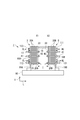
- (A) is a front view which shows schematic structure of the plate type heat exchanger which concerns on embodiment of this invention
- (b) is the top view.
- (A)-(c) shows the step which removes the heat-transfer plate of embodiment of FIG. 1 in steps. It is a top view which shows the outline of the plate type heat exchanger which concerns on other embodiment of this invention. It is a front view which shows schematic structure of the plate type heat exchanger which concerns on other embodiment of this invention. It is a front view which shows schematic structure of the plate type heat exchanger which concerns on further another embodiment of this invention.
- (A)-(c) shows the process of removing the heat-transfer plate of embodiment shown in FIG. 5 in steps.
- FIG. 7 It is a front view which shows schematic structure of the plate type heat exchanger which concerns on other embodiment of this invention.
- (A) And (b) shows a part of process of removing the heat-transfer plate of embodiment shown in FIG. 7 in steps.
- (C) to (e) show a part of the step of removing the heat transfer plate of the embodiment shown in FIG. 7 step by step.
- the plate heat exchanger 1 of the present embodiment has a first heat exchange unit 3 and a second heat exchange unit 5 having a refrigerant flow path independent of the first heat exchange unit 3. It is installed on the surface plate 90 with an interval in the length direction L.
- heat transfer plates 30 each having a gasket (not shown) installed on the heat transfer surface 33 are adjacent to each other so that the heat transfer surfaces 33 face each other. Are arranged in a stacked state.
- the heat transfer plates 30 arranged in this way are fastened and fixed by bolts 41 and nuts 43.
- the first heat exchange unit 3 includes a first fixed support 10A that supports the plurality of first heat transfer plates 30A from one end side in the arrangement direction, and the other end in the arrangement direction of the plurality of first heat transfer plates 30A. And a first moving support 20A supported from the side.
- the first fixed support 10A is composed of a rectangular plate member as shown in FIGS. 1 (a) and 1 (b).
- the first fixed support 10A is provided so as to rise in the vertical direction from the surface plate 90 so that its position is fixed.
- the first fixed support 10A is provided with a bolt hole 13 into which the bolt 41 is inserted so as to penetrate the front and back.
- bolt holes 13 are provided at six places in total, that is, three places in the height direction H and two places in the width direction W. Yes.
- the first fixed support 10A includes an introduction path 11 for allowing the high-temperature fluid HL and the low-temperature fluid CL to flow from the outside, and a discharge path 12 for discharging the high-temperature fluid HL and the low-temperature fluid CL after heat exchange.
- the introduction passages 11 are provided at two positions spaced apart in the diagonal direction of the first fixed support 10A.
- One introduction passage 111 is used for introduction of the high-temperature fluid HL, and the other introduction passage 112 is the low-temperature fluid. Used to introduce CL.
- the discharge passages 12 are also provided at two positions spaced apart in the diagonal direction of the first fixed support 10A.
- One discharge passage 12 (121) is used for discharging the high-temperature fluid HL, and the other discharge passage 12 is provided. (122) is used to discharge the low temperature fluid CL.
- the introduction path 11 and the discharge path 12 described above are merely examples, and other arrangements may be adopted.
- the first moving support 20A is composed of a rectangular plate member as shown in FIGS. 1 (a) and 1 (b).
- the first moving support 20A is supported by the pair of upper guide 15 and lower guide 17 so as to be movable in the length direction L.
- the first moving support 20A is provided with a guide hole 21 through which the upper guide 15 is inserted through the front and back, and a guide groove 25 into which the lower guide 17 is inserted at the lower end.
- the first moving support 20A is provided with a bolt hole 23 into which the bolt 41 is inserted so as to penetrate the front and back.
- bolt holes 23 are provided at six places in total, three places in the height direction H and two places in the width direction W. Yes.
- the first moving support 20A is arranged along the vertical direction and is parallel to the first fixed support 10A. Further, when the first moving support 20A supports the plurality of first heat transfer plates 30A together with the first fixed support 10A, the thickness of the plurality of first heat transfer plates 30A from the first fixed support 10A. It arrange
- the first heat transfer plate 30A has an upper guide groove 31 into which the upper guide 15 is inserted at the center of the upper end in the width direction W. Similarly, a lower guide groove 35 into which the lower guide 17 is inserted is formed in the center of the lower end in the width direction W.
- the heat transfer plate 30 When the upper guide 15 is inserted into the upper guide groove 31 and the lower guide 17 is inserted into the lower guide groove 35, the heat transfer plate 30 is movable while being guided by the upper guide 15 and the lower guide 17. The heat transfer plate 30 moves when the plate heat exchanger 1 is maintained and inspected.
- the plurality of bolts 41 are connected to the plurality of first transmissions via the first fixed support 10A and the first moving support 20A.
- the heat plate 30A is tightened. Therefore, each bolt 41 is provided through the bolt hole 13 of the first fixed support 10A and the bolt hole 23 of the first moving support 20A.
- the bolt 41 has such a length that the nut 43 is fitted to the bolt 41 and the plurality of first heat transfer plates 30A can be tightened via the first fixed support 10A and the first moving support 20A.
- the outer diameter of the nut 43 is larger than the diameters of the bolt hole 13 and the bolt hole 23.
- the second heat exchange unit 5 is configured in the same manner as the first heat exchange unit 3. Specifically, the second fixed support body 10B that supports the plurality of second heat transfer plates 30B from one end side in the arrangement direction and the plurality of second heat transfer plates 30B from the other end side in the arrangement direction. Second moving support 20B. Then, like the first moving support 20A, the second moving support 20B moves from the second support position X2 to the second retracted position Y2 when performing maintenance / inspection of the plate heat exchanger 1. (See FIG. 1 (a)). In this embodiment, the 1st heat exchange part 3 and the 2nd heat exchange part 5 are provided with the same number of heat-transfer plates 30 of the same specification.
- the second heat transfer plate 30B is the same as the first heat transfer plate 30A
- the second fixed support 10B is the same as the first fixed support 10A
- the second moving support 20B is the same as the first moving support 20A, but a different one from that constituting the first heat exchange unit 3 may be used.
- the upper guide 15 is a rod that suspends and supports the movement of the respective moving support bodies 20 of the first heat exchange unit 3 and the second heat exchange unit 5 from above. It is a member.
- the upper guide 15 has one end fixed to the first fixed support 10A of the first heat exchange unit 3 and the other end fixed to the second fixed support 10B of the second heat exchange unit 5. It is provided over the part 3 and the second heat exchange part 5.
- the axial direction of the upper guide 15 is arranged in parallel with the first heat transfer plate 30 ⁇ / b> A and the second moving support body 20 ⁇ / b> B along the length direction L.
- the upper guide 15 is inserted into the guide holes 21 of the first moving support 20A and the second moving support 20B without any gap, so that the first moving support 20A and the second moving support 20B are guided to the upper guide 15. However, it is movable in the length direction L.
- the upper guide 15 is an upper common guide that enables the first moving support 20A and the second moving support 20B to move in the length direction L, that is, an upper common guide.
- the upper guide 15 can be appropriately selected from a circular shape and a rectangular shape regardless of the cross-sectional form. The same applies to the lower guide 17.
- the lower guide 17 moves the movement support 20 and the plurality of heat transfer plates 30 of the first heat exchange unit 3 and the second heat exchange unit 5 downward. It is the rod-shaped member supported from.
- One end of the lower guide 17 is fixed to the first fixed support 10 ⁇ / b> A of the first heat exchange unit 3, and the other end is fixed to the second fixed support 10 ⁇ / b> B of the second heat exchange unit 5. It is provided over the part 3 and the second heat exchange part 5.
- the lower guide 17 is preferably inserted into the guide groove 25 of the first moving support 20A and the second moving support 20B and the lower guide groove 35 of the heat transfer plate 30 without a gap.
- the first moving support 20 ⁇ / b> A and the second moving support 20 ⁇ / b> B can move in the length direction L while being guided by the lower guide 17.
- the lower guide 17 is arranged such that its axial direction is parallel to the direction of arrangement of the heat transfer plates 30 and along the length direction L.
- the lower guide 17 is more common than the common guide for moving the first moving support 20A and the second moving support 20B in the length direction L, that is, the upper common guide (upper guide 15). It is provided at a relatively lower position and serves as a lower common guide.
- the plate heat exchanger 1 configured as described above includes an upper guide 15 and a lower guide. 17 are connected.
- the upper guide 15 and the lower guide 17 have such a length that the first heat exchange part 3 and the second heat exchange part 5 can be connected via the first removal area A1 and the second removal area A2.
- the first moving support 20A is moved from the first support position X1 while being guided by the upper guide 15 and the lower guide 17 during maintenance and inspection of the plate heat exchanger 1. It can move to the first retracted position Y1.
- the first retraction position Y1 is separated from the first support position X1 by a predetermined distance in the direction of the arrangement of the first heat transfer plates 30A.
- a first removal region A1 in which the first heat transfer plate 30A is removed is formed. Therefore, the distance from the first support position X1 to the first retracted position Y1, that is, the dimension in the length direction L of the first removal region A1, is set to an extent sufficient to remove the first heat transfer plate 30A.
- FIG. 2B shows an example in which the first moving support 20A of the first heat exchanging unit 3 moves, but the second moving support 20B of the second heat exchanging unit 5 is reversed. It moves in the direction and reaches the second retracted position Y2.
- a second removal region A2 is formed between the second support position X2 and the second retracted position Y2 (see FIG. 1A).
- the second removal area A2 is also set in the same manner as the first removal area A1.
- the 1st heat exchange part 3 and the 2nd heat exchange part 5 are provided with the same number of heat-transfer plates 30 of the same specification, the length of 1st removal area A1 and 2nd removal area A2 The dimension in the length direction L is equal.
- A1 A2
- the first heat exchange unit 3 and the second heat exchange unit 5 are arranged so that the first moving support 20A and the second moving support 20B face each other.
- the interval I between the first moving support 20A and the second moving support 20B is smaller than the sum of the first removal area A1 and the second removal area A2.
- region A2 overlap. Therefore, when the first moving support 20A moves to the first retracted position Y1, the first moving area A1 and the second removing area A2 are moved.
- the second moving support 20B moves to the second retracted position Y2, the second moving support 20B moves in the second removal area A2 and in the first removal area A1.
- the 1st heat exchange part 3 and the 2nd heat exchange part 5 share a part of 1st removal area
- the interval I is preferably equal to the larger dimension in the length direction L of the first removal region A1 and the second removal region A2. Thereby, both removal area
- interval I is slightly larger than the dimension of the length direction L of 1st removal area
- the first heat exchange unit 3 and the second heat exchange unit 5 are either in a side view (see FIG. 1 (a)) or in a plan view (see FIG. 1 (b)).
- the center of the first moving support 20A and the center of the second moving support 20B are arranged on the same straight line. Thereby, 1st removal area A1 and 2nd removal area A2 can be made to overlap reliably.
- FIG. 2 shows a step of removing the first heat transfer plate 30 ⁇ / b> A from the first heat exchange unit 3.
- all nuts 43 related to the fastening of the first moving support 20A are removed, and the fastening of the first moving support 20A by the bolt 41 and the nut 43 is released,
- the movable support 20A is movable to the first retracted position Y1 side.
- the first moving support body 20A is moved from the first support position X1 to the first retracted position Y1, thereby forming the first removal region A1.
- the first moving support 20A is supported by and guided by the upper guide 15 and the lower guide 17, so that the first moving support 20A can smoothly move to the retracted position Y.
- the first heat transfer plate 30A to be removed is moved to the first removal region A1.
- the first heat transfer plate 30 ⁇ / b> A is guided by the lower guide 17 through the lower guide groove 35.
- the lower guide groove 35 of the first heat transfer plate 30A is moved down the lower guide 17 by tilting the moved first heat transfer plate 30A in the first removal region A1.
- the first heat transfer plate 30 ⁇ / b> A disengaged from the lower guide 17 is pulled out and removed from the first heat exchange unit 3.
- the operation of removing the first heat transfer plate 30A is performed by moving the first heat transfer plate 30A to the first removal region A1 in the order closer to the first moving support 20A moving to the first retracted position Y1. One by one.
- the plate heat exchanger 1 has two heat exchangers, a first heat exchanging unit 3 and a second heat exchanging unit 5, but the first removal area A1 of the first heat exchanging unit 3
- the second removal area A2 of the two heat exchange unit 5 is shared. Therefore, the space occupied by the plate heat exchanger 1 can be reduced as compared with the case where the first removal area A1 and the second removal area A2 are independently provided at different locations. Therefore, the plate heat exchanger 1 can be suitably used even when the installation space is limited by an offshore plant or the like.
- the plate heat exchanger 1 includes the first heat exchange unit 3 and the second heat exchange unit 5 which are two heat exchangers, so that one unit is a main heat exchanger and the other unit is another unit. Can be used as an auxiliary heat exchanger.
- the first heat exchanging unit 3 is used as the main heat exchanger to exchange heat, and when a problem occurs in the first heat exchanging unit 3, the second heat exchanging unit 5 that is a sub heat exchanger is switched to. Heat exchange. Therefore, the plate heat exchanger 1 can continue the heat exchange even if a problem such as failure of one occurs.
- the movement support bodies 20 of the first heat exchange unit 3 and the second heat exchange unit 5 face each other, and Since the centers are arranged on the same straight line, the first removal region A1 and the second removal region A2 are shared between the first heat exchange unit 3 and the second heat exchange unit 5 arranged on the straight line. can do. Therefore, most of the first removal area A1 and the second removal area A2 can be overlapped by adjusting the distance between the first heat exchange section 3 and the second heat exchange section 5, so that the plate heat exchanger 1 The dimension in the length direction L can be minimized. Ideally, the space occupied by the first removal area A1 and the second removal area A2 can be minimized by overlapping the entire first removal area A1 and the second removal area A2.
- the present invention is not limited to this, for example, the first removal area A1 and the second removal area A2 Even if each of the two removal areas A2 overlaps by 1 ⁇ 2, the space occupied by the removal area can be reduced by 1 ⁇ 2.
- the wider the range in which each of the first removal area A1 and the second removal area A2 overlaps the wider the space occupied by the removal area can be saved.
- the plate heat exchanger 1 is provided with an upper guide 15 between the first heat exchanging unit 3 and the second heat exchanging unit 5, and the first moving support 20 ⁇ / b> A and the second moving support 20 ⁇ / b> B are connected to the upper guide 15. 15 can be moved while guiding.
- the first support position X1 and the first retracted position Y1 and the second support position X2 and the first support position X1 are removed without removing the respective moving support bodies 20 of the first heat exchange unit 3 and the second heat exchange unit 5. Since it can be moved between the two retreat positions Y2, the burden of the work of removing the heat transfer plate 30 can be reduced.
- the plate-type heat exchanger 1 showed the example by which the 1st heat exchange part 3 and the 2nd heat exchange part 5 were arrange
- the plate heat exchanger 1 may be crunched, L-shaped, or U-shaped in plan view. Thereby, the surrounding environment where the plate-type heat exchanger 1 is installed may be used more efficiently.
- the lower guide 17 is used as a lower shared guide in the first heat exchange unit 3 and the second heat exchange unit 5, but overlaps with the first removal region A1 and the second removal region A2. It may be missing at some points.
- the first heat exchanging portion 3 is provided with a first independent guide 19A having one end supported by the first fixed support 10A and the other end facing the first removal region A1.
- the second heat exchanging part 5 is provided with a second independent guide 19B having one end supported by the second fixed support 10B and the other end facing the second removal region A2.
- a gap is formed between the leading ends of the independent guide 19A and the second independent guide 19B.
- the dimension in the length direction L of the first removal area A1 and the second removal area A2 is equal, but the dimensions of the first removal area A1 and the second removal area A2 are the same. May be different.
- the first removal region A1 and the second removal region A1 are associated with it.
- the dimension of one length direction L of outer region A2 can be made larger than the other.
- the upper guide 15 penetrates the guide hole 21 of the moving support 20 and the moving support 20 can move in the length direction L, but the lower guide 17 corresponds to the guide hole 21. You may move the movement support body 20 by providing a thing. Thereby, it is not necessary to provide the upper guide 15, and it can be removed by lifting the heat transfer plate 30 slightly.
- the bolt 41 used in the second embodiment passes through the bolt hole 23 and the bolt hole 13 in this order, as shown in FIG.
- the nut 43 fitted to the bolt 41 is pressed against the main surface on which the introduction path 11 of the fixed support 10 is provided, and the group of heat transfer plates 30 are tightened.
- the nut 43 protrudes from the fixed support 10 and has a length that allows the nut 43 to be fitted.
- the plate heat exchanger 1 of the present embodiment configured as described above removes the heat transfer plate 30 as follows.
- the nut 43 is removed, and the movable support body 20 that can be moved to the retracted position Y side, and the stacked structure that can be similarly moved to the retracted position Y side.
- the group of heat transfer plates 30 are moved until the movable support 20 is located at the retracted position Y.
- the bolt 41 comes out of the bolt hole 13, and a removal area A is formed between the fixed support 10 and the tip of the bolt 41.
- each heat transfer plate 30 to be removed is moved to the fixed support 10 side. Then, as shown in FIG. 6C, the moved heat transfer plate 30 is tilted to remove the lower guide 17 from the lower guide groove of the heat transfer plate 30. Then, the heat transfer plate 30 from which the lower guide 17 is removed is pulled out and removed.
- the position of the group of heat transfer plates 30 can be changed from the position at which the group of heat transfer plates 30 are normally attached to the plate heat exchanger 1, so that a person other than those who are replacing It can be made clear to the user that the work is being taken out.
- the fixed support 10 used in the third embodiment is not formed with the bolt hole 13, but is formed with a fitting groove 14 into which the bolt 41 is fitted.
- the bolt hole 23 is not formed in the moving support body 20, but the insertion groove
- the plate heat exchanger 1 of the present embodiment configured as described above removes the heat transfer plate 30 as follows. 8 shows a process until the bolt 41 and the nut 43 are removed, and FIG. 9 shows a process until the heat transfer plate 30 is removed after the bolt 41 is removed.
- the movable support 20 that can be moved to the retracted position Y side is moved to the retracted position Y. Thereby, the removal area A is formed.
- the heat transfer plate 30 to be removed is moved into the outer region A in the formed outer region A.
- the lower side of the moved heat transfer plate 30 is tilted, and the lower guide 17 is removed from the lower guide groove of the heat transfer plate 30. Then, the heat transfer plate 30 from which the lower guide 17 is removed is pulled out and removed.
- the removal area A can be reduced.
Landscapes
- Engineering & Computer Science (AREA)
- Physics & Mathematics (AREA)
- Thermal Sciences (AREA)
- Mechanical Engineering (AREA)
- General Engineering & Computer Science (AREA)
- Heat-Exchange Devices With Radiators And Conduit Assemblies (AREA)
Abstract
La présente invention concerne un échangeur de chaleur de type à plaques 1 comportant une première section d'échange de chaleur 3 et une seconde section d'échange de chaleur 5 qui est dotée d'un passage d'écoulement de fluide frigorigène indépendante de la première section d'échange de chaleur 3. La première section d'échange de chaleur 3 et la seconde section d'échange de chaleur 5 sont dotées chacune: d'un corps de support de fixation pour le support d'une pluralité de plaques de transfert thermique 30 disposées de sorte que les surfaces de transfert de chaleur 33de plaques de transfert thermique adjacentes sont se font face mutuellement, le corps de support de fixation 10 assurant le support de la pluralité de plaques de transfert thermique 30 depuis une extrémité dans la direction d'agencement; et d'un corps de support de mouvement 20 pour le support de la pluralité de plaques de transfert thermique 30 à une première position de support X1 située sur l'autre côté d'extrémité dans la direction d'agencement. L'échangeur de chaleur de type à plaques est caractérisé en ce que le corps de support de mouvement 20 se déplace depuis la première position de support X1vers une position escamotée Y1 à une certaine distance de la première position de support X1 dans la direction d'agencement, formant ainsi une première région de démontage A1 entre la première position de support X1 et la seconde position escamotée Y1, et les plaques de transfert thermique 30 sont retirées depuis la première région de retrait A1, la première région de retrait A1de la première section d'échange de chaleur 3 et une seconde région de retrait A2 de la seconde section d'échange de chaleur 5 étant communes.
Priority Applications (2)
| Application Number | Priority Date | Filing Date | Title |
|---|---|---|---|
| PCT/JP2016/000672 WO2017138037A1 (fr) | 2016-02-09 | 2016-02-09 | Échangeur de chaleur du type à plaques |
| US16/076,925 US10731927B2 (en) | 2016-02-09 | 2016-02-09 | Dual plate-type heat exchanger with removable plates |
Applications Claiming Priority (1)
| Application Number | Priority Date | Filing Date | Title |
|---|---|---|---|
| PCT/JP2016/000672 WO2017138037A1 (fr) | 2016-02-09 | 2016-02-09 | Échangeur de chaleur du type à plaques |
Publications (1)
| Publication Number | Publication Date |
|---|---|
| WO2017138037A1 true WO2017138037A1 (fr) | 2017-08-17 |
Family
ID=59562934
Family Applications (1)
| Application Number | Title | Priority Date | Filing Date |
|---|---|---|---|
| PCT/JP2016/000672 Ceased WO2017138037A1 (fr) | 2016-02-09 | 2016-02-09 | Échangeur de chaleur du type à plaques |
Country Status (2)
| Country | Link |
|---|---|
| US (1) | US10731927B2 (fr) |
| WO (1) | WO2017138037A1 (fr) |
Cited By (2)
| Publication number | Priority date | Publication date | Assignee | Title |
|---|---|---|---|---|
| CN117928276A (zh) * | 2024-03-25 | 2024-04-26 | 江苏海洋冷却设备有限公司 | 一种用于冷却塔热交换器组件的定位机构 |
| JP7566366B2 (ja) | 2022-06-01 | 2024-10-15 | 株式会社Hino-Tec | 熱交換器 |
Families Citing this family (1)
| Publication number | Priority date | Publication date | Assignee | Title |
|---|---|---|---|---|
| CN114111397B (zh) * | 2021-12-08 | 2023-10-10 | 江阴市亚龙换热设备有限公司 | 一种可拆式换热器 |
Citations (6)
| Publication number | Priority date | Publication date | Assignee | Title |
|---|---|---|---|---|
| JPS5942470U (ja) * | 1982-09-14 | 1984-03-19 | 日立冷熱株式会社 | プレ−ト式熱交換器 |
| JPS61161577U (fr) * | 1985-03-22 | 1986-10-06 | ||
| JPH0391695A (ja) * | 1989-08-31 | 1991-04-17 | Hisaka Works Ltd | プレート式熱交換器 |
| JPH03112659U (fr) * | 1990-03-05 | 1991-11-18 | ||
| JPH0694387A (ja) * | 1992-09-10 | 1994-04-05 | Hisaka Works Ltd | プレート式熱交換器 |
| JP2014505224A (ja) * | 2011-01-10 | 2014-02-27 | アルファ・ラバル・コーポレイト・エービー | プレート熱交換器 |
Family Cites Families (12)
| Publication number | Priority date | Publication date | Assignee | Title |
|---|---|---|---|---|
| NL58202C (fr) * | 1938-05-30 | |||
| US2610834A (en) * | 1947-02-24 | 1952-09-16 | Cherry Burrell Corp | Plate type heat exchanger |
| US2777674A (en) * | 1953-05-29 | 1957-01-15 | Creamery Package Mfg Co | Plate type heat exchanger |
| US2939686A (en) * | 1955-02-04 | 1960-06-07 | Cherry Burrell Corp | Double port heat exchanger plate |
| US3099520A (en) * | 1960-02-10 | 1963-07-30 | Separator Ab | Method and apparatus for preventing infection of heat exchange chambers |
| US3196937A (en) * | 1963-09-24 | 1965-07-27 | Rosenblads Patenter Ab | Two unit plate heat exchanger with end supports |
| GB1129924A (en) * | 1966-03-30 | 1968-10-09 | Apv Co Ltd | Improvements in or relating to plate heat transfer apparatus |
| SE332005B (fr) * | 1969-06-13 | 1971-01-25 | Alfa Laval Ab | |
| US3862661A (en) * | 1970-01-16 | 1975-01-28 | Leonid Maximovich Kovalenko | Corrugated plate for heat exchanger and heat exchanger with said corrugated plate |
| US4090556A (en) * | 1976-05-10 | 1978-05-23 | Almqvist Christer Anders Hjalm | Means for locating plate elements in a device, such as a heat exchanger, filter, or the like |
| JPH0688691A (ja) | 1992-09-08 | 1994-03-29 | Hisaka Works Ltd | プレート式熱交換器 |
| US6899163B2 (en) * | 2003-03-24 | 2005-05-31 | Apv North America, Inc. | Plate heat exchanger and method for using the same |
-
2016
- 2016-02-09 WO PCT/JP2016/000672 patent/WO2017138037A1/fr not_active Ceased
- 2016-02-09 US US16/076,925 patent/US10731927B2/en not_active Expired - Fee Related
Patent Citations (6)
| Publication number | Priority date | Publication date | Assignee | Title |
|---|---|---|---|---|
| JPS5942470U (ja) * | 1982-09-14 | 1984-03-19 | 日立冷熱株式会社 | プレ−ト式熱交換器 |
| JPS61161577U (fr) * | 1985-03-22 | 1986-10-06 | ||
| JPH0391695A (ja) * | 1989-08-31 | 1991-04-17 | Hisaka Works Ltd | プレート式熱交換器 |
| JPH03112659U (fr) * | 1990-03-05 | 1991-11-18 | ||
| JPH0694387A (ja) * | 1992-09-10 | 1994-04-05 | Hisaka Works Ltd | プレート式熱交換器 |
| JP2014505224A (ja) * | 2011-01-10 | 2014-02-27 | アルファ・ラバル・コーポレイト・エービー | プレート熱交換器 |
Cited By (3)
| Publication number | Priority date | Publication date | Assignee | Title |
|---|---|---|---|---|
| JP7566366B2 (ja) | 2022-06-01 | 2024-10-15 | 株式会社Hino-Tec | 熱交換器 |
| CN117928276A (zh) * | 2024-03-25 | 2024-04-26 | 江苏海洋冷却设备有限公司 | 一种用于冷却塔热交换器组件的定位机构 |
| CN117928276B (zh) * | 2024-03-25 | 2024-05-31 | 江苏海洋冷却设备有限公司 | 一种用于冷却塔热交换器组件的定位机构 |
Also Published As
| Publication number | Publication date |
|---|---|
| US20190049196A1 (en) | 2019-02-14 |
| US10731927B2 (en) | 2020-08-04 |
Similar Documents
| Publication | Publication Date | Title |
|---|---|---|
| CN103282736B (zh) | 板式换热器 | |
| WO2017138037A1 (fr) | Échangeur de chaleur du type à plaques | |
| JP6741462B2 (ja) | 航空機胴体パネルのハンドリング方法 | |
| RU2473037C1 (ru) | Пластинчатый теплообменник | |
| US20180320989A1 (en) | Heat exchanger | |
| US20120000637A1 (en) | Plate, heat exchanger and method of manufacturing a heat exchanger | |
| KR101576691B1 (ko) | 엔진의 배기 가스를 위한 가스용 열 교환기 | |
| US20150129166A1 (en) | Tube Support for Vibration Mitigation | |
| JP6052204B2 (ja) | 鋼板の冷却装置 | |
| US10215502B2 (en) | Heat exchanger | |
| JP2015532707A (ja) | 熱交換器のための交換器要素、このような交換器要素を備える熱交換器、及びこのような交換器要素を製作するための方法 | |
| JP2007283314A (ja) | 線引き装置 | |
| KR200484258Y1 (ko) | 열교환기의 커버 플랜지 거치대 | |
| US10066880B2 (en) | Air-cooled heat exchanger system | |
| JP5762237B2 (ja) | 多管式熱交換器 | |
| CN115172232B (zh) | 一种晶舟和半导体工艺设备 | |
| CN216144234U (zh) | 一种双层管板结构 | |
| JP5915429B2 (ja) | 熱交換器 | |
| KR101578332B1 (ko) | 반도체 웨이퍼 반송 지그 | |
| CN201350496Y (zh) | 板坯弯曲段框架与自由辊连接的过渡装置 | |
| JP5644668B2 (ja) | ボールねじ | |
| CA2907856A1 (fr) | Procede de nettoyage d'echangeur de chaleur a plaques et echangeur de chaleur a plaques | |
| JP4630811B2 (ja) | 核燃料集合体 | |
| JPH01238771A (ja) | 圧力容器 | |
| JP3214342U (ja) | 組合せ式熱交換器 |
Legal Events
| Date | Code | Title | Description |
|---|---|---|---|
| 121 | Ep: the epo has been informed by wipo that ep was designated in this application |
Ref document number: 16889746 Country of ref document: EP Kind code of ref document: A1 |
|
| NENP | Non-entry into the national phase |
Ref country code: DE |
|
| 122 | Ep: pct application non-entry in european phase |
Ref document number: 16889746 Country of ref document: EP Kind code of ref document: A1 |
|
| NENP | Non-entry into the national phase |
Ref country code: JP |