WO2017138037A1 - プレート式熱交換器 - Google Patents
プレート式熱交換器 Download PDFInfo
- Publication number
- WO2017138037A1 WO2017138037A1 PCT/JP2016/000672 JP2016000672W WO2017138037A1 WO 2017138037 A1 WO2017138037 A1 WO 2017138037A1 JP 2016000672 W JP2016000672 W JP 2016000672W WO 2017138037 A1 WO2017138037 A1 WO 2017138037A1
- Authority
- WO
- WIPO (PCT)
- Prior art keywords
- heat exchange
- support
- heat
- plate
- moving support
- Prior art date
- Legal status (The legal status is an assumption and is not a legal conclusion. Google has not performed a legal analysis and makes no representation as to the accuracy of the status listed.)
- Ceased
Links
Images


Classifications
-
- F—MECHANICAL ENGINEERING; LIGHTING; HEATING; WEAPONS; BLASTING
- F28—HEAT EXCHANGE IN GENERAL
- F28F—DETAILS OF HEAT-EXCHANGE AND HEAT-TRANSFER APPARATUS, OF GENERAL APPLICATION
- F28F9/00—Casings; Header boxes; Auxiliary supports for elements; Auxiliary members within casings
- F28F9/007—Auxiliary supports for elements
- F28F9/0075—Supports for plates or plate assemblies
-
- F—MECHANICAL ENGINEERING; LIGHTING; HEATING; WEAPONS; BLASTING
- F28—HEAT EXCHANGE IN GENERAL
- F28D—HEAT-EXCHANGE APPARATUS, NOT PROVIDED FOR IN ANOTHER SUBCLASS, IN WHICH THE HEAT-EXCHANGE MEDIA DO NOT COME INTO DIRECT CONTACT
- F28D9/00—Heat-exchange apparatus having stationary plate-like or laminated conduit assemblies for both heat-exchange media, the media being in contact with different sides of a conduit wall
- F28D9/0093—Multi-circuit heat-exchangers, e.g. integrating different heat exchange sections in the same unit or heat-exchangers for more than two fluids
-
- F—MECHANICAL ENGINEERING; LIGHTING; HEATING; WEAPONS; BLASTING
- F28—HEAT EXCHANGE IN GENERAL
- F28F—DETAILS OF HEAT-EXCHANGE AND HEAT-TRANSFER APPARATUS, OF GENERAL APPLICATION
- F28F3/00—Plate-like or laminated elements; Assemblies of plate-like or laminated elements
- F28F3/08—Elements constructed for building-up into stacks, e.g. capable of being taken apart for cleaning
- F28F3/083—Elements constructed for building-up into stacks, e.g. capable of being taken apart for cleaning capable of being taken apart
-
- F—MECHANICAL ENGINEERING; LIGHTING; HEATING; WEAPONS; BLASTING
- F28—HEAT EXCHANGE IN GENERAL
- F28F—DETAILS OF HEAT-EXCHANGE AND HEAT-TRANSFER APPARATUS, OF GENERAL APPLICATION
- F28F9/00—Casings; Header boxes; Auxiliary supports for elements; Auxiliary members within casings
-
- F—MECHANICAL ENGINEERING; LIGHTING; HEATING; WEAPONS; BLASTING
- F28—HEAT EXCHANGE IN GENERAL
- F28F—DETAILS OF HEAT-EXCHANGE AND HEAT-TRANSFER APPARATUS, OF GENERAL APPLICATION
- F28F9/00—Casings; Header boxes; Auxiliary supports for elements; Auxiliary members within casings
- F28F9/007—Auxiliary supports for elements
-
- F—MECHANICAL ENGINEERING; LIGHTING; HEATING; WEAPONS; BLASTING
- F28—HEAT EXCHANGE IN GENERAL
- F28F—DETAILS OF HEAT-EXCHANGE AND HEAT-TRANSFER APPARATUS, OF GENERAL APPLICATION
- F28F2275/00—Fastening; Joining
- F28F2275/20—Fastening; Joining with threaded elements
- F28F2275/205—Fastening; Joining with threaded elements with of tie-rods
-
- F—MECHANICAL ENGINEERING; LIGHTING; HEATING; WEAPONS; BLASTING
- F28—HEAT EXCHANGE IN GENERAL
- F28F—DETAILS OF HEAT-EXCHANGE AND HEAT-TRANSFER APPARATUS, OF GENERAL APPLICATION
- F28F2280/00—Mounting arrangements; Arrangements for facilitating assembling or disassembling of heat exchanger parts
- F28F2280/02—Removable elements
-
- F—MECHANICAL ENGINEERING; LIGHTING; HEATING; WEAPONS; BLASTING
- F28—HEAT EXCHANGE IN GENERAL
- F28F—DETAILS OF HEAT-EXCHANGE AND HEAT-TRANSFER APPARATUS, OF GENERAL APPLICATION
- F28F2280/00—Mounting arrangements; Arrangements for facilitating assembling or disassembling of heat exchanger parts
- F28F2280/06—Adapter frames, e.g. for mounting heat exchanger cores on other structure and for allowing fluidic connections
Definitions
- the present invention relates to a plate heat exchanger.
- the plate heat exchanger has a fixed support and a moving support in the heat exchanging section, and the moving support is attached to be movable in the long axis direction of the guide bar.
- a thin heat transfer plate in which irregularities are formed by pressing is provided with a sealing gasket installed in a laminated form.
- the heat transfer plate and gasket attached to the plate heat exchanger may be removed for maintenance of the plate heat exchanger.
- the moving support is moved in the long axis direction of the guide bar, and the heat transfer plate is removed, for example, the heat transfer plate is inclined and the guide bar is removed from the guide groove formed in the heat transfer plate.
- the plate-type heat exchanger has a removal area that is an area for moving the moving support and removing the heat transfer frame when the heat transfer frame is removed. Since this removal area is always provided with a guide bar or the like, it is not used for other purposes during normal operation, and is used only during maintenance and inspections that are not so frequent. Thus, the removal area secured in the plate heat exchanger unnecessarily occupies the installation space for the plate heat exchanger during normal operation.
- Patent Document 1 a heat transfer plate between a fixed support and a movable support is provided, and a nut in which a bolt is screwed and fixed to both ends of a sleeve having a predetermined length and a nut in which a bolt is screwed through are provided.
- a plate-type heat exchanger that is fastened and fixed with a fastening bracket is disclosed. According to the plate-type heat exchanger of Patent Document 1, since the bolt does not protrude from the moving support, the removal region can be effectively used for other purposes during normal operation.
- multiple units typically two plate-type heat exchangers, are equipped with multiple heat exchangers, one serving as the main heat exchanger and the other serving as the secondary heat exchanger, which is always the main heat exchanger. It is preferable to perform heat exchange with a heat exchanger and switch to a sub heat exchanger to perform heat exchange when a problem occurs.
- two plate-type heat exchangers are simply arranged, the required number of removal areas are required, so that it is impossible to answer an application that requires space saving.
- an object of the present invention is to provide a heat exchanger that can suppress the space occupied by the removal region while including two plate-type heat exchangers.
- the present invention relates to a plate heat exchanger including a first heat exchanging part and a second heat exchanging part having a refrigerant flow path independent of the first heat exchanging part.
- the first heat exchanging portion in the present invention includes a first fixed support that supports a plurality of first heat transfer plates arranged adjacent to each other with their heat transfer surfaces facing each other from one end side in the direction of arrangement. And a first moving support that supports the plurality of first heat transfer plates at a first support position on one end side in the arrangement direction.
- the first heat exchanging unit moves the first moving support body from the first support position to a first retracted position that is separated from the first support position and between the first support position and the first retracted position.
- the second heat exchanging portion in the present invention includes a second fixed support that supports a plurality of second heat transfer plates arranged adjacent to each other with their heat transfer surfaces facing each other from one end side in the direction of arrangement. And a second moving support that supports the plurality of second heat transfer plates at a second support position on one end side in the arrangement direction.
- the second heat exchanging unit moves the second moving support body from the second support position to the second retracted position separated in the direction of the array, and moves the second moving support body between the second support position and the second retracted position.
- a removal area is formed and the second heat transfer plate is removed from the second removal area.
- the plate type heat exchanger of this invention is characterized by sharing the 1st removal area
- the first heat exchange unit and the second heat exchange unit are configured such that the first movement support of the first heat exchange unit and the second movement support of the second heat exchange unit face each other. It is preferable that they are arranged.
- the dimension in the direction of the arrangement of the first removal region of the first heat exchange part is equal to the dimension in the direction of the arrangement of the second removal region of the second heat exchange part. Is preferred.
- the plate heat exchanger of the present invention includes a common guide that is supported at one end by the first fixed support of the first heat exchange unit and supported at the other end by the second fixed support of the second heat exchange unit.
- the first moving support body is moved from the first support position to the first retracted position while being guided by the common guide, and the second moving support body is second retracted from the second support position while being guided by the common guide. It is preferable to move to a position.
- a pair of common guides provided at different positions in the height direction, and an upper common guide that is a common guide provided relatively above and a relative position relative to the upper common guide
- a lower common guide that is a common guide provided below the upper common guide suspends and supports the first moving support and the second support, and the lower common guide includes the first moving support and It is preferable that the second support is supported from below in the height direction.
- one end side is supported by the first fixed support body of the first heat exchange section, and the other end faces the first removal region, and the second heat exchange section A second independent guide having one end supported by the second fixed support and the other end facing the second removal region, wherein the first independent guide and the second independent guide are the same at different positions from the common guide.
- the common guide suspends and supports the first moving support and the second moving support, and the first independent guide supports the first moving support from below in the height direction.
- the two independent guides preferably support the second moving support from below in the height direction.
- the first heat exchange unit and the second heat exchange unit are combined by sharing the removal region of the first heat exchange unit and the removal region of the second heat exchange unit.
- the space occupied by the removal region can be suppressed. Therefore, according to the heat exchanger of the present invention, for example, heat exchange is always performed in the first heat exchange unit, and when a problem occurs, the heat exchange is realized by switching to the second heat exchange unit in an application where space saving is required. it can.
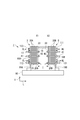
- (A) is a front view which shows schematic structure of the plate type heat exchanger which concerns on embodiment of this invention
- (b) is the top view.
- (A)-(c) shows the step which removes the heat-transfer plate of embodiment of FIG. 1 in steps. It is a top view which shows the outline of the plate type heat exchanger which concerns on other embodiment of this invention. It is a front view which shows schematic structure of the plate type heat exchanger which concerns on other embodiment of this invention. It is a front view which shows schematic structure of the plate type heat exchanger which concerns on further another embodiment of this invention.
- (A)-(c) shows the process of removing the heat-transfer plate of embodiment shown in FIG. 5 in steps.
- FIG. 7 It is a front view which shows schematic structure of the plate type heat exchanger which concerns on other embodiment of this invention.
- (A) And (b) shows a part of process of removing the heat-transfer plate of embodiment shown in FIG. 7 in steps.
- (C) to (e) show a part of the step of removing the heat transfer plate of the embodiment shown in FIG. 7 step by step.
- the plate heat exchanger 1 of the present embodiment has a first heat exchange unit 3 and a second heat exchange unit 5 having a refrigerant flow path independent of the first heat exchange unit 3. It is installed on the surface plate 90 with an interval in the length direction L.
- heat transfer plates 30 each having a gasket (not shown) installed on the heat transfer surface 33 are adjacent to each other so that the heat transfer surfaces 33 face each other. Are arranged in a stacked state.
- the heat transfer plates 30 arranged in this way are fastened and fixed by bolts 41 and nuts 43.
- the first heat exchange unit 3 includes a first fixed support 10A that supports the plurality of first heat transfer plates 30A from one end side in the arrangement direction, and the other end in the arrangement direction of the plurality of first heat transfer plates 30A. And a first moving support 20A supported from the side.
- the first fixed support 10A is composed of a rectangular plate member as shown in FIGS. 1 (a) and 1 (b).
- the first fixed support 10A is provided so as to rise in the vertical direction from the surface plate 90 so that its position is fixed.
- the first fixed support 10A is provided with a bolt hole 13 into which the bolt 41 is inserted so as to penetrate the front and back.
- bolt holes 13 are provided at six places in total, that is, three places in the height direction H and two places in the width direction W. Yes.
- the first fixed support 10A includes an introduction path 11 for allowing the high-temperature fluid HL and the low-temperature fluid CL to flow from the outside, and a discharge path 12 for discharging the high-temperature fluid HL and the low-temperature fluid CL after heat exchange.
- the introduction passages 11 are provided at two positions spaced apart in the diagonal direction of the first fixed support 10A.
- One introduction passage 111 is used for introduction of the high-temperature fluid HL, and the other introduction passage 112 is the low-temperature fluid. Used to introduce CL.
- the discharge passages 12 are also provided at two positions spaced apart in the diagonal direction of the first fixed support 10A.
- One discharge passage 12 (121) is used for discharging the high-temperature fluid HL, and the other discharge passage 12 is provided. (122) is used to discharge the low temperature fluid CL.
- the introduction path 11 and the discharge path 12 described above are merely examples, and other arrangements may be adopted.
- the first moving support 20A is composed of a rectangular plate member as shown in FIGS. 1 (a) and 1 (b).
- the first moving support 20A is supported by the pair of upper guide 15 and lower guide 17 so as to be movable in the length direction L.
- the first moving support 20A is provided with a guide hole 21 through which the upper guide 15 is inserted through the front and back, and a guide groove 25 into which the lower guide 17 is inserted at the lower end.
- the first moving support 20A is provided with a bolt hole 23 into which the bolt 41 is inserted so as to penetrate the front and back.
- bolt holes 23 are provided at six places in total, three places in the height direction H and two places in the width direction W. Yes.
- the first moving support 20A is arranged along the vertical direction and is parallel to the first fixed support 10A. Further, when the first moving support 20A supports the plurality of first heat transfer plates 30A together with the first fixed support 10A, the thickness of the plurality of first heat transfer plates 30A from the first fixed support 10A. It arrange
- the first heat transfer plate 30A has an upper guide groove 31 into which the upper guide 15 is inserted at the center of the upper end in the width direction W. Similarly, a lower guide groove 35 into which the lower guide 17 is inserted is formed in the center of the lower end in the width direction W.
- the heat transfer plate 30 When the upper guide 15 is inserted into the upper guide groove 31 and the lower guide 17 is inserted into the lower guide groove 35, the heat transfer plate 30 is movable while being guided by the upper guide 15 and the lower guide 17. The heat transfer plate 30 moves when the plate heat exchanger 1 is maintained and inspected.
- the plurality of bolts 41 are connected to the plurality of first transmissions via the first fixed support 10A and the first moving support 20A.
- the heat plate 30A is tightened. Therefore, each bolt 41 is provided through the bolt hole 13 of the first fixed support 10A and the bolt hole 23 of the first moving support 20A.
- the bolt 41 has such a length that the nut 43 is fitted to the bolt 41 and the plurality of first heat transfer plates 30A can be tightened via the first fixed support 10A and the first moving support 20A.
- the outer diameter of the nut 43 is larger than the diameters of the bolt hole 13 and the bolt hole 23.
- the second heat exchange unit 5 is configured in the same manner as the first heat exchange unit 3. Specifically, the second fixed support body 10B that supports the plurality of second heat transfer plates 30B from one end side in the arrangement direction and the plurality of second heat transfer plates 30B from the other end side in the arrangement direction. Second moving support 20B. Then, like the first moving support 20A, the second moving support 20B moves from the second support position X2 to the second retracted position Y2 when performing maintenance / inspection of the plate heat exchanger 1. (See FIG. 1 (a)). In this embodiment, the 1st heat exchange part 3 and the 2nd heat exchange part 5 are provided with the same number of heat-transfer plates 30 of the same specification.
- the second heat transfer plate 30B is the same as the first heat transfer plate 30A
- the second fixed support 10B is the same as the first fixed support 10A
- the second moving support 20B is the same as the first moving support 20A, but a different one from that constituting the first heat exchange unit 3 may be used.
- the upper guide 15 is a rod that suspends and supports the movement of the respective moving support bodies 20 of the first heat exchange unit 3 and the second heat exchange unit 5 from above. It is a member.
- the upper guide 15 has one end fixed to the first fixed support 10A of the first heat exchange unit 3 and the other end fixed to the second fixed support 10B of the second heat exchange unit 5. It is provided over the part 3 and the second heat exchange part 5.
- the axial direction of the upper guide 15 is arranged in parallel with the first heat transfer plate 30 ⁇ / b> A and the second moving support body 20 ⁇ / b> B along the length direction L.
- the upper guide 15 is inserted into the guide holes 21 of the first moving support 20A and the second moving support 20B without any gap, so that the first moving support 20A and the second moving support 20B are guided to the upper guide 15. However, it is movable in the length direction L.
- the upper guide 15 is an upper common guide that enables the first moving support 20A and the second moving support 20B to move in the length direction L, that is, an upper common guide.
- the upper guide 15 can be appropriately selected from a circular shape and a rectangular shape regardless of the cross-sectional form. The same applies to the lower guide 17.
- the lower guide 17 moves the movement support 20 and the plurality of heat transfer plates 30 of the first heat exchange unit 3 and the second heat exchange unit 5 downward. It is the rod-shaped member supported from.
- One end of the lower guide 17 is fixed to the first fixed support 10 ⁇ / b> A of the first heat exchange unit 3, and the other end is fixed to the second fixed support 10 ⁇ / b> B of the second heat exchange unit 5. It is provided over the part 3 and the second heat exchange part 5.
- the lower guide 17 is preferably inserted into the guide groove 25 of the first moving support 20A and the second moving support 20B and the lower guide groove 35 of the heat transfer plate 30 without a gap.
- the first moving support 20 ⁇ / b> A and the second moving support 20 ⁇ / b> B can move in the length direction L while being guided by the lower guide 17.
- the lower guide 17 is arranged such that its axial direction is parallel to the direction of arrangement of the heat transfer plates 30 and along the length direction L.
- the lower guide 17 is more common than the common guide for moving the first moving support 20A and the second moving support 20B in the length direction L, that is, the upper common guide (upper guide 15). It is provided at a relatively lower position and serves as a lower common guide.
- the plate heat exchanger 1 configured as described above includes an upper guide 15 and a lower guide. 17 are connected.
- the upper guide 15 and the lower guide 17 have such a length that the first heat exchange part 3 and the second heat exchange part 5 can be connected via the first removal area A1 and the second removal area A2.
- the first moving support 20A is moved from the first support position X1 while being guided by the upper guide 15 and the lower guide 17 during maintenance and inspection of the plate heat exchanger 1. It can move to the first retracted position Y1.
- the first retraction position Y1 is separated from the first support position X1 by a predetermined distance in the direction of the arrangement of the first heat transfer plates 30A.
- a first removal region A1 in which the first heat transfer plate 30A is removed is formed. Therefore, the distance from the first support position X1 to the first retracted position Y1, that is, the dimension in the length direction L of the first removal region A1, is set to an extent sufficient to remove the first heat transfer plate 30A.
- FIG. 2B shows an example in which the first moving support 20A of the first heat exchanging unit 3 moves, but the second moving support 20B of the second heat exchanging unit 5 is reversed. It moves in the direction and reaches the second retracted position Y2.
- a second removal region A2 is formed between the second support position X2 and the second retracted position Y2 (see FIG. 1A).
- the second removal area A2 is also set in the same manner as the first removal area A1.
- the 1st heat exchange part 3 and the 2nd heat exchange part 5 are provided with the same number of heat-transfer plates 30 of the same specification, the length of 1st removal area A1 and 2nd removal area A2 The dimension in the length direction L is equal.
- A1 A2
- the first heat exchange unit 3 and the second heat exchange unit 5 are arranged so that the first moving support 20A and the second moving support 20B face each other.
- the interval I between the first moving support 20A and the second moving support 20B is smaller than the sum of the first removal area A1 and the second removal area A2.
- region A2 overlap. Therefore, when the first moving support 20A moves to the first retracted position Y1, the first moving area A1 and the second removing area A2 are moved.
- the second moving support 20B moves to the second retracted position Y2, the second moving support 20B moves in the second removal area A2 and in the first removal area A1.
- the 1st heat exchange part 3 and the 2nd heat exchange part 5 share a part of 1st removal area
- the interval I is preferably equal to the larger dimension in the length direction L of the first removal region A1 and the second removal region A2. Thereby, both removal area
- interval I is slightly larger than the dimension of the length direction L of 1st removal area
- the first heat exchange unit 3 and the second heat exchange unit 5 are either in a side view (see FIG. 1 (a)) or in a plan view (see FIG. 1 (b)).
- the center of the first moving support 20A and the center of the second moving support 20B are arranged on the same straight line. Thereby, 1st removal area A1 and 2nd removal area A2 can be made to overlap reliably.
- FIG. 2 shows a step of removing the first heat transfer plate 30 ⁇ / b> A from the first heat exchange unit 3.
- all nuts 43 related to the fastening of the first moving support 20A are removed, and the fastening of the first moving support 20A by the bolt 41 and the nut 43 is released,
- the movable support 20A is movable to the first retracted position Y1 side.
- the first moving support body 20A is moved from the first support position X1 to the first retracted position Y1, thereby forming the first removal region A1.
- the first moving support 20A is supported by and guided by the upper guide 15 and the lower guide 17, so that the first moving support 20A can smoothly move to the retracted position Y.
- the first heat transfer plate 30A to be removed is moved to the first removal region A1.
- the first heat transfer plate 30 ⁇ / b> A is guided by the lower guide 17 through the lower guide groove 35.
- the lower guide groove 35 of the first heat transfer plate 30A is moved down the lower guide 17 by tilting the moved first heat transfer plate 30A in the first removal region A1.
- the first heat transfer plate 30 ⁇ / b> A disengaged from the lower guide 17 is pulled out and removed from the first heat exchange unit 3.
- the operation of removing the first heat transfer plate 30A is performed by moving the first heat transfer plate 30A to the first removal region A1 in the order closer to the first moving support 20A moving to the first retracted position Y1. One by one.
- the plate heat exchanger 1 has two heat exchangers, a first heat exchanging unit 3 and a second heat exchanging unit 5, but the first removal area A1 of the first heat exchanging unit 3
- the second removal area A2 of the two heat exchange unit 5 is shared. Therefore, the space occupied by the plate heat exchanger 1 can be reduced as compared with the case where the first removal area A1 and the second removal area A2 are independently provided at different locations. Therefore, the plate heat exchanger 1 can be suitably used even when the installation space is limited by an offshore plant or the like.
- the plate heat exchanger 1 includes the first heat exchange unit 3 and the second heat exchange unit 5 which are two heat exchangers, so that one unit is a main heat exchanger and the other unit is another unit. Can be used as an auxiliary heat exchanger.
- the first heat exchanging unit 3 is used as the main heat exchanger to exchange heat, and when a problem occurs in the first heat exchanging unit 3, the second heat exchanging unit 5 that is a sub heat exchanger is switched to. Heat exchange. Therefore, the plate heat exchanger 1 can continue the heat exchange even if a problem such as failure of one occurs.
- the movement support bodies 20 of the first heat exchange unit 3 and the second heat exchange unit 5 face each other, and Since the centers are arranged on the same straight line, the first removal region A1 and the second removal region A2 are shared between the first heat exchange unit 3 and the second heat exchange unit 5 arranged on the straight line. can do. Therefore, most of the first removal area A1 and the second removal area A2 can be overlapped by adjusting the distance between the first heat exchange section 3 and the second heat exchange section 5, so that the plate heat exchanger 1 The dimension in the length direction L can be minimized. Ideally, the space occupied by the first removal area A1 and the second removal area A2 can be minimized by overlapping the entire first removal area A1 and the second removal area A2.
- the present invention is not limited to this, for example, the first removal area A1 and the second removal area A2 Even if each of the two removal areas A2 overlaps by 1 ⁇ 2, the space occupied by the removal area can be reduced by 1 ⁇ 2.
- the wider the range in which each of the first removal area A1 and the second removal area A2 overlaps the wider the space occupied by the removal area can be saved.
- the plate heat exchanger 1 is provided with an upper guide 15 between the first heat exchanging unit 3 and the second heat exchanging unit 5, and the first moving support 20 ⁇ / b> A and the second moving support 20 ⁇ / b> B are connected to the upper guide 15. 15 can be moved while guiding.
- the first support position X1 and the first retracted position Y1 and the second support position X2 and the first support position X1 are removed without removing the respective moving support bodies 20 of the first heat exchange unit 3 and the second heat exchange unit 5. Since it can be moved between the two retreat positions Y2, the burden of the work of removing the heat transfer plate 30 can be reduced.
- the plate-type heat exchanger 1 showed the example by which the 1st heat exchange part 3 and the 2nd heat exchange part 5 were arrange
- the plate heat exchanger 1 may be crunched, L-shaped, or U-shaped in plan view. Thereby, the surrounding environment where the plate-type heat exchanger 1 is installed may be used more efficiently.
- the lower guide 17 is used as a lower shared guide in the first heat exchange unit 3 and the second heat exchange unit 5, but overlaps with the first removal region A1 and the second removal region A2. It may be missing at some points.
- the first heat exchanging portion 3 is provided with a first independent guide 19A having one end supported by the first fixed support 10A and the other end facing the first removal region A1.
- the second heat exchanging part 5 is provided with a second independent guide 19B having one end supported by the second fixed support 10B and the other end facing the second removal region A2.
- a gap is formed between the leading ends of the independent guide 19A and the second independent guide 19B.
- the dimension in the length direction L of the first removal area A1 and the second removal area A2 is equal, but the dimensions of the first removal area A1 and the second removal area A2 are the same. May be different.
- the first removal region A1 and the second removal region A1 are associated with it.
- the dimension of one length direction L of outer region A2 can be made larger than the other.
- the upper guide 15 penetrates the guide hole 21 of the moving support 20 and the moving support 20 can move in the length direction L, but the lower guide 17 corresponds to the guide hole 21. You may move the movement support body 20 by providing a thing. Thereby, it is not necessary to provide the upper guide 15, and it can be removed by lifting the heat transfer plate 30 slightly.
- the bolt 41 used in the second embodiment passes through the bolt hole 23 and the bolt hole 13 in this order, as shown in FIG.
- the nut 43 fitted to the bolt 41 is pressed against the main surface on which the introduction path 11 of the fixed support 10 is provided, and the group of heat transfer plates 30 are tightened.
- the nut 43 protrudes from the fixed support 10 and has a length that allows the nut 43 to be fitted.
- the plate heat exchanger 1 of the present embodiment configured as described above removes the heat transfer plate 30 as follows.
- the nut 43 is removed, and the movable support body 20 that can be moved to the retracted position Y side, and the stacked structure that can be similarly moved to the retracted position Y side.
- the group of heat transfer plates 30 are moved until the movable support 20 is located at the retracted position Y.
- the bolt 41 comes out of the bolt hole 13, and a removal area A is formed between the fixed support 10 and the tip of the bolt 41.
- each heat transfer plate 30 to be removed is moved to the fixed support 10 side. Then, as shown in FIG. 6C, the moved heat transfer plate 30 is tilted to remove the lower guide 17 from the lower guide groove of the heat transfer plate 30. Then, the heat transfer plate 30 from which the lower guide 17 is removed is pulled out and removed.
- the position of the group of heat transfer plates 30 can be changed from the position at which the group of heat transfer plates 30 are normally attached to the plate heat exchanger 1, so that a person other than those who are replacing It can be made clear to the user that the work is being taken out.
- the fixed support 10 used in the third embodiment is not formed with the bolt hole 13, but is formed with a fitting groove 14 into which the bolt 41 is fitted.
- the bolt hole 23 is not formed in the moving support body 20, but the insertion groove
- the plate heat exchanger 1 of the present embodiment configured as described above removes the heat transfer plate 30 as follows. 8 shows a process until the bolt 41 and the nut 43 are removed, and FIG. 9 shows a process until the heat transfer plate 30 is removed after the bolt 41 is removed.
- the movable support 20 that can be moved to the retracted position Y side is moved to the retracted position Y. Thereby, the removal area A is formed.
- the heat transfer plate 30 to be removed is moved into the outer region A in the formed outer region A.
- the lower side of the moved heat transfer plate 30 is tilted, and the lower guide 17 is removed from the lower guide groove of the heat transfer plate 30. Then, the heat transfer plate 30 from which the lower guide 17 is removed is pulled out and removed.
- the removal area A can be reduced.
Landscapes
- Engineering & Computer Science (AREA)
- Physics & Mathematics (AREA)
- Thermal Sciences (AREA)
- Mechanical Engineering (AREA)
- General Engineering & Computer Science (AREA)
- Heat-Exchange Devices With Radiators And Conduit Assemblies (AREA)
Abstract
第一熱交換部3と、第一熱交換部3とは独立する冷媒流路を備える第二熱交換部5と、を備えるプレート式熱交換器1であって、第一熱交換部3と第二熱交換部5のそれぞれが、互いに隣接する同士が伝熱面33を対向して配列される複数の伝熱プレート30を、配列の方向の一方端側から支持する固定支持体10と、複数の伝熱プレート30を、配列の方向の他方端側の第一支持位置X1で支持する移動支持体20と、を備え、移動支持体20を第一支持位置X1から、配列の方向に離れた退避位置Y1に移動させて、第一支持位置X1から第二退避位置Y1の間に第一取外領域A1を形成し、伝熱プレート30を第一取外領域A1から取り外すものであり、第一熱交換部3の第一取外領域A1と第二熱交換部5の第二取外領域A2が共有されている、ことを特徴とするプレート式熱交換器。
Description
本発明は、プレート式熱交換器に関する。
プレート式熱交換器は、熱交換部に、固定支持体と移動支持体とを有し、移動支持体は、ガイドバーの長軸方向に移動可能に取付けられている。固定プレートと移動プレートとの間に、プレス加工により凹凸が形成された薄い伝熱プレートに、シール用のガスケットを設置したものが、積層状になって取り付けられている。それにより、伝熱プレートが積層化してできた隙間に、熱源が流れる流路と、熱源と温度の異なる作動媒体が流れる冷媒流路が交互に形成され、それらの流路に熱源や作動媒体が流れることによって、高効率な熱交換が行われる。
プレート式熱交換器に取り付けた伝熱プレート及びガスケットは、プレート式熱交換器の保守・整備のため、取り外される場合がある。その際には、移動支持体をガイドバーの長軸方向に移動させ、例えば伝熱プレートを斜めにして伝熱プレートに形成されたガイド溝からガイドバーを取り外す等の、伝熱プレートを取り外すための作業を行う。そのため、プレート式熱交換器には、伝熱フレームを取の外す際に移動支持体の移動及び伝熱フレームの取り外し作業を行う領域である取外領域が確保されている。この取外領域は、ガイドバー等が常時設けられているので、通常運転時には他の目的に使用されることはなく、それほど頻度の多くない保守・点検時にのみ使用される。このように、プレート式熱交換器に確保されている取外領域は、通常運転時にはプレート式熱交換器の設置スペースを不必要に占有する。
特許文献1には、固定支持体と移動支持体との間の伝熱プレートを、所定長さ寸法のスリーブの両端にボルトを螺合固着したナットとボルトを螺合貫通したナットをそれぞれ設けた締付金具で締付固定したプレート式熱交換器が開示されている。特許文献1のプレート式熱交換器によれば、移動支持体からボルトがはみ出さないので、通常運転時に取外領域を他の目的に有効利用することができる。
ところで、熱交換部に問題が発生したときに、熱交換を継続できることが望まれる。そこで、複数台、典型的には二台のプレート式熱交換器に複数の熱交換部を設け、一台を主熱交換器とし、もう一台を副熱交換器とし、常時は主熱交換器で熱交換を行い、問題発生時には副熱交換器に切り替えて熱交換を行うことが好ましい。しかし、二台のプレート式熱交換器を単純に配置すれば、配置した数だけ取外領域が必要になるので、省スペースが要求される用途に答えることができない。
以上より本発明は、二台のプレート式熱交換器を備えながらも、取外領域が占有するスペースを抑えることのできる熱交換器を提供することを目的とする。
本発明は、第一熱交換部と、第一熱交換部とは独立する冷媒流路を備える第二熱交換部と、を備えるプレート式熱交換器に関する。
本発明における第一熱交換部は、互いに隣接する同士が伝熱面を対向して配列される複数の第一伝熱プレートを、配列の方向の一方端側から支持する第一固定支持体と、複数の第一伝熱プレートを、配列の方向の一方端側の第一支持位置で支持する第一移動支持体と、を備える。
また、第一熱交換部は、第一移動支持体を第一支持位置から、配列の方向に離れた第一退避位置に移動させて、第一支持位置から第一退避位置の間に第一取外領域を形成し、第一伝熱プレートを第一取外領域から取り外す。
本発明における第二熱交換部は、互いに隣接する同士が伝熱面を対向して配列される複数の第二伝熱プレートを、配列の方向の一方端側から支持する第二固定支持体と、複数の第二伝熱プレートを、配列の方向の一方端側の第二支持位置で支持する第二移動支持体と、を備える。
また、第二熱交換部は、第二移動支持体を第二支持位置から、配列の方向に離れた第二退避位置に移動させて、第二支持位置から第二退避位置の間に第二取外領域を形成し、第二伝熱プレートを第二取外領域から取り外する。
そして、本発明のプレート式熱交換器は、第一熱交換部の第一取外領域と第二熱交換部の第二取外領域が共有されていることを特徴とする。
本発明のプレート式熱交換器において、第一熱交換部と第二熱交換部は、第一熱交換部の第一移動支持体と第二熱交換部の第二移動支持体が対向して配置される、ことが好ましい。
本発明のプレート式熱交換器において、第一熱交換部の第一取外領域の配列の方向の寸法と、第二熱交換部の第二取外領域の配列の方向の寸法が等しい、ことが好ましい。
本発明のプレート式熱交換器において、第一熱交換部の第一固定支持体に一方端側が支持され、第二熱交換部の第二固定支持体に他方端が支持される共通ガイドを備え、第一移動支持体は、共通ガイドに案内されながら、第一支持位置から第一退避位置まで移動し、第二移動支持体は、共通ガイドに案内されながら、第二支持位置から第二退避位置まで移動する、ことが好ましい。
本発明のプレート式熱交換器において、高さ方向の異なる位置に設けられる、一対の共通ガイドを備え、相対的に上方に設けられる共通ガイドである上方共通ガイドと、上方共通ガイドよりも相対的に下方に設けられる共通ガイドである下方共通ガイドと、を備え、上方共通ガイドは、第一移動支持体及び第二支持体を吊り下げて支持し、下方共通ガイドは、第一移動支持体及び第二支持体を高さ方向の下方から支持する、ことが好ましい。
本発明のプレート式熱交換器において、第一熱交換部の第一固定支持体に一方端側が支持され、他方端が第一取外領域に臨む第一独立ガイドと、第二熱交換部の第二固定支持体に一方端側が支持され、他方端が第二取外領域に臨む第二独立ガイドと、を備え、第一独立ガイドと第二独立ガイドは、共通ガイドと異なる位置において、同一直線上に配置され、共通ガイドは、第一移動支持体及び第二移動支持体を吊り下げて支持し、第一独立ガイドは、第一移動支持体を高さ方向の下方から支持し、第二独立ガイドは、第二移動支持体を高さ方向の下方から支持する、ことが好ましい。
本発明によれば、第一熱交換部の取外領域と第二熱交換部の取外領域の取外領域とを共有することにより、第一熱交換部と第二熱交換部を合せた熱交換器全体として、取外領域が占有するスペースを抑えることができる。したがって、本発明の熱交換器によれば、例えば常時は第一熱交換部で熱交換を行い、問題発生時には第二熱交換部に切り替えて熱交換を、省スペースが要求される用途において実現できる。
以下、添付図面を参照しながら、本発明に係るプレート式熱交換器の実施形態について説明する。
[第一実施形態]
本実施形態のプレート式熱交換器1は、図1に示すように、第一熱交換部3と、第一熱交換部3とは独立する冷媒流路を備える第二熱交換部5を有しており、長さ方向Lに間隔を空けて、定盤90の上に設置されている。各々の第一熱交換部3及び第二熱交換部5には、伝熱面33にガスケット(図示略)が設置された伝熱プレート30が、互いに隣接する同士が伝熱面33を対向して積層された状態で配列されている。このように配列された伝熱プレート30は、ボルト41と、ナット43により、締め付けられて固定されている。伝熱プレート30が締付けられることにより、隣接する伝熱プレート30,30同士の間に、高温流体HLが流れる流路、又は、低温流体CLが流れる冷媒流路が形成される。
本実施形態のプレート式熱交換器1は、図1に示すように、第一熱交換部3と、第一熱交換部3とは独立する冷媒流路を備える第二熱交換部5を有しており、長さ方向Lに間隔を空けて、定盤90の上に設置されている。各々の第一熱交換部3及び第二熱交換部5には、伝熱面33にガスケット(図示略)が設置された伝熱プレート30が、互いに隣接する同士が伝熱面33を対向して積層された状態で配列されている。このように配列された伝熱プレート30は、ボルト41と、ナット43により、締め付けられて固定されている。伝熱プレート30が締付けられることにより、隣接する伝熱プレート30,30同士の間に、高温流体HLが流れる流路、又は、低温流体CLが流れる冷媒流路が形成される。
まず、第一熱交換部3について説明する。第一熱交換部3は、複数の第一伝熱プレート30Aを配列の方向の一方端側から支持する第一固定支持体10Aと、複数の第一伝熱プレート30Aを配列の方向の他方端側から支持する第一移動支持体20Aと、を有している。
第一固定支持体10Aは、図1(a),(b)に示すように、矩形の板状部材から構成されている。第一固定支持体10Aは、その位置が固定されるように、定盤90から鉛直方向に立ち上がって設けられている。第一固定支持体10Aは、ボルト41が挿入されるボルト孔13が表裏を貫通して設けられている。本実施形態では一例として、図1(a),(b)に示すように、ボルト孔13は、高さ方向Hに3カ所と幅方向Wに2カ所の、合わせて6カ所に設けられている。
第一固定支持体10Aは、外部から高温流体HL及び低温流体CLを流入させるための導入路11と、熱交換を終えた高温流体HL及び低温流体CLを排出させるための排出路12を備えている。
導入路11は、第一固定支持体10Aの対角線方向に間隔を空けた2カ所に設けられており、一方の導入路111が高温流体HLの導入に用いられ、他方の導入路112が低温流体CLの導入に用いられる。
排出路12も、第一固定支持体10Aの対角線方向に間隔を空けた2カ所に設けられており、一方の排出路12(121)が高温流体HLの排出に用いられ、他方の排出路12(122)が低温流体CLの排出に用いられる。
以上の導入路11と排出路12はあくまで一例であり、他の配列を採用してもよい。
導入路11は、第一固定支持体10Aの対角線方向に間隔を空けた2カ所に設けられており、一方の導入路111が高温流体HLの導入に用いられ、他方の導入路112が低温流体CLの導入に用いられる。
排出路12も、第一固定支持体10Aの対角線方向に間隔を空けた2カ所に設けられており、一方の排出路12(121)が高温流体HLの排出に用いられ、他方の排出路12(122)が低温流体CLの排出に用いられる。
以上の導入路11と排出路12はあくまで一例であり、他の配列を採用してもよい。
第一移動支持体20Aは、図1(a),(b)に示すように、矩形の板状部材から構成されている。第一移動支持体20Aは、一対の上方ガイド15と下方ガイド17に支持されることにより、長さ方向Lに移動が可能に設けられている。そのために、第一移動支持体20Aは、上方ガイド15が挿入されるガイド孔21が表裏を貫通して設けられるとともに、下方端には下方ガイド17が挿入されるガイド溝25が設けられている。第一移動支持体20Aは、ボルト41が挿入されるボルト孔23が表裏を貫通して設けられている。本実施形態では一例として、図1(a),(b)に示すように、ボルト孔23が、高さ方向Hに3カ所と幅方向Wに2カ所の、合わせて6カ所に設けられている。
第一移動支持体20Aは、鉛直方向に沿って配置されており、第一固定支持体10Aと平行をなしている。
また、第一移動支持体20Aは、第一固定支持体10Aとともに複数の第一伝熱プレート30A支持しているときに、第一固定支持体10Aから複数の第一伝熱プレート30Aの厚さの合計した分だけ離れた位置である第一支持位置X1に配置される。第一移動支持体20Aは、プレート式熱交換器1の運転中はこの第一支持位置X1にいて、第一固定支持体10Aとともに第一伝熱プレート30Aを支持するが、プレート式熱交換器1の保守・点検を行う際には、後述する第一退避位置Y1に移動する。
また、第一移動支持体20Aは、第一固定支持体10Aとともに複数の第一伝熱プレート30A支持しているときに、第一固定支持体10Aから複数の第一伝熱プレート30Aの厚さの合計した分だけ離れた位置である第一支持位置X1に配置される。第一移動支持体20Aは、プレート式熱交換器1の運転中はこの第一支持位置X1にいて、第一固定支持体10Aとともに第一伝熱プレート30Aを支持するが、プレート式熱交換器1の保守・点検を行う際には、後述する第一退避位置Y1に移動する。
第一伝熱プレート30Aは、矩形の板状部材から構成されており、第一固定支持体10Aと第一移動支持体20Aの間に複数設置されて、積層化されている。積層化された第一伝熱プレート30Aにおいて、導入された高温流体HLと導入された低温流体CLの間で熱交換がなされる。
第一伝熱プレート30Aは、図1(b)に示すように、上端の幅方向Wの中央に、上方ガイド15が挿入される上方ガイド溝31が形成されている。同様に、下端の幅方向Wの中央には、下方ガイド17が挿入される下方ガイド溝35が形成されている。上方ガイド溝31に上方ガイド15が挿入され、下方ガイド溝35に下方ガイド17が挿入されることで、伝熱プレート30は、上方ガイド15及び下方ガイド17に案内されながら移動可能である。伝熱プレート30は、プレート式熱交換器1の保守・点検を行う際に、移動する。
第一伝熱プレート30Aは、図1(b)に示すように、上端の幅方向Wの中央に、上方ガイド15が挿入される上方ガイド溝31が形成されている。同様に、下端の幅方向Wの中央には、下方ガイド17が挿入される下方ガイド溝35が形成されている。上方ガイド溝31に上方ガイド15が挿入され、下方ガイド溝35に下方ガイド17が挿入されることで、伝熱プレート30は、上方ガイド15及び下方ガイド17に案内されながら移動可能である。伝熱プレート30は、プレート式熱交換器1の保守・点検を行う際に、移動する。
複数のボルト41は、図1(a),(b)に示すように、各々が対応するナット43とともに、第一固定支持体10Aと第一移動支持体20Aを介して、複数の第一伝熱プレート30Aを締め付ける。そのために、各々のボルト41は、第一固定支持体10Aのボルト孔13及び第一移動支持体20Aのボルト孔23が貫通して設けられる。
ボルト41は、ナット43をボルト41に嵌合させて、第一固定支持体10Aと第一移動支持体20Aを介して、複数の第一伝熱プレート30Aを締め付けられる程度の長さを有する。そして、ナット43の外径は、ボルト孔13及びボルト孔23の直径よりも大きい。それにより、第一移動支持体20Aは、嵌合したナット43によりボルト孔23周縁の主面が第一支持位置X1に押されて、第一支持位置X1に移動する。
ボルト41は、ナット43をボルト41に嵌合させて、第一固定支持体10Aと第一移動支持体20Aを介して、複数の第一伝熱プレート30Aを締め付けられる程度の長さを有する。そして、ナット43の外径は、ボルト孔13及びボルト孔23の直径よりも大きい。それにより、第一移動支持体20Aは、嵌合したナット43によりボルト孔23周縁の主面が第一支持位置X1に押されて、第一支持位置X1に移動する。
次に、第二熱交換部5について説明する。第二熱交換部5は、第一熱交換部3と同様に構成されている。具体的には、複数の第二伝熱プレート30Bを配列の方向の一方端側から支持する第二固定支持体10Bと、複数の第二伝熱プレート30Bを配列の方向の他方端側から支持する第二移動支持体20Bと、を有している。そして、第二移動支持体20Bは、第一移動支持体20Aと同様に、プレート式熱交換器1の保守・点検を行う際には、第二支持位置X2から第二退避位置Y2に移動する(図1(a)参照)。本実施形態では、第一熱交換部3と第二熱交換部5が、同じ仕様の伝熱プレート30を同じ数だけ備えている。
本実施形態では、第二伝熱プレート30Bは、第一伝熱プレート30Aと同じものであり、第二固定支持体10Bは、第一固定支持体10Aと同じものであり、第二移動支持体20Bは、第一移動支持体20Aと同じものであるが、第一熱交換部3を構成するものと異なるものを用いてもよい。
本実施形態では、第二伝熱プレート30Bは、第一伝熱プレート30Aと同じものであり、第二固定支持体10Bは、第一固定支持体10Aと同じものであり、第二移動支持体20Bは、第一移動支持体20Aと同じものであるが、第一熱交換部3を構成するものと異なるものを用いてもよい。
上方ガイド15は、図1(a),(b)に示すように、第一熱交換部3及び第二熱交換部5の各々の移動支持体20の移動を上方から吊り下げて支持する棒状の部材である。
上方ガイド15は、一端が第一熱交換部3の第一固定支持体10Aに固定され、他端が第二熱交換部5の第二固定支持体10Bに固定されており、第一熱交換部3と第二熱交換部5にわたって設けられている。上方ガイド15は、その軸方向が、第一伝熱プレート30A及び第二移動支持体20Bと配列の方向と平行に、かつ、長さ方向Lに沿って配置されている。
上方ガイド15は、一端が第一熱交換部3の第一固定支持体10Aに固定され、他端が第二熱交換部5の第二固定支持体10Bに固定されており、第一熱交換部3と第二熱交換部5にわたって設けられている。上方ガイド15は、その軸方向が、第一伝熱プレート30A及び第二移動支持体20Bと配列の方向と平行に、かつ、長さ方向Lに沿って配置されている。
上方ガイド15は、第一移動支持体20A及び第二移動支持体20Bのガイド孔21に隙間なく挿入されることで、第一移動支持体20A及び第二移動支持体20Bは上方ガイド15に案内されながら長さ方向Lに移動可能になっている。このように本実施形態では、上方ガイド15が第一移動支持体20A及び第二移動支持体20Bを長さ方向Lに移動可能にする上方の共通ガイド、すなわち上方共通ガイドになっている。
なお、上方ガイド15は、断面の形態は問わず、円形、矩形など適宜選択できる。下方ガイド17も同様である。
なお、上方ガイド15は、断面の形態は問わず、円形、矩形など適宜選択できる。下方ガイド17も同様である。
下方ガイド17は、図1(a),(b)に示すように、第一熱交換部3及び第二熱交換部5の各々の移動支持体20及び複数の伝熱プレート30の移動を下方から支持する棒状の部材である。
下方ガイド17は、一端が第一熱交換部3の第一固定支持体10Aに固定され、他端が第二熱交換部5の第二固定支持体10Bに固定されており、第一熱交換部3と第二熱交換部5にわたって設けられている。
下方ガイド17は、第一移動支持体20A及び第二移動支持体20Bのガイド溝25及び伝熱プレート30の下方ガイド溝35に好ましくは隙間なく挿入される。それにより、第一移動支持体20A及び第二移動支持体20Bは、下方ガイド17に案内されながら長さ方向Lに移動可能になっている。下方ガイド17は、その軸方向が、伝熱プレート30を配列の方向と平行に、かつ、長さ方向Lに沿って配置されている。このように本実施形態では、下方ガイド17が第一移動支持体20A及び第二移動支持体20Bを長さ方向Lに移動させるための共通のガイド、すなわち上方共通ガイド(上方ガイド15)よりも相対的に下方に設けられ下方共通ガイドになっている。
以上のように構成されるプレート式熱交換器1は、図1(a),(b)に示すように、第一熱交換部3と第二熱交換部5が、上方ガイド15及び下方ガイド17により連結されている。上方ガイド15及び下方ガイド17は、第一熱交換部3と第二熱交換部5を、第一取外領域A1,第二取外領域A2を介して連結できる長さを有している。
そして、図2(b)に示すように、第一移動支持体20Aは、プレート式熱交換器1の保守・点検時には、上方ガイド15及び下方ガイド17に案内されながら、第一支持位置X1から第一退避位置Y1まで移動することができる。第一退避位置Y1は、第一支持位置X1から第一伝熱プレート30Aの配列の方向に所定の距離だけ離れている。第一伝熱プレート30Aが第一退避位置Y1に移動することにより、第一伝熱プレート30Aの取外し作業を行う第一取外領域A1が形成される。したがって、第一支持位置X1から第一退避位置Y1までの距離、つまり第一取外領域A1の長さ方向Lの寸法は、第一伝熱プレート30Aを取り外すのに足りる程度に設定される。
なお、図2(b)は、第一熱交換部3の第一移動支持体20Aが移動する場合の例を示しているが、第二熱交換部5の第二移動支持体20Bは、逆方向に移動して第二退避位置Y2に達する。それにより、第二支持位置X2と第二退避位置Y2の間に、第二取外領域A2が形成される(図1(a)参照)。第二取外領域A2も、第一取外領域A1と同様に設定される。本実施形態では、第一熱交換部3と第二熱交換部5が同じ仕様の伝熱プレート30を同じ数だけ備えているので、第一取外領域A1と第二取外領域A2の長さ方向Lの寸法が、等しい。
A1=A2
A1=A2
第一熱交換部3と第二熱交換部5は、図1(a)に示すように、第一移動支持体20Aと第二移動支持体20Bが対向するように配置されている。第一移動支持体20Aと第二移動支持体20Bの間隔Iは、第一取外領域A1と第二取外領域A2の合計よりも小さくなっている。それにより、第一取外領域A1の一部と第二取外領域A2の一部が重複する。そのため、第一移動支持体20Aが第一退避位置Y1へ移動すれば、第一取外領域A1を移動するとともに、第二取外領域A2を移動することになる。同様に、第二移動支持体20Bも、第二退避位置Y2へ移動すれば、第二取外領域A2を移動するとともに、第一取外領域A1を移動することになる。このように、第一熱交換部3と第二熱交換部5は、互いに第一取外領域A1の一部と第二取外領域A2の一部を共有する。
I<A1+A2
I<A1+A2
間隔Iは、第一取外領域A1及び第二取外領域A2の長さ方向Lの寸法の大きい方と等しいことが好ましい。それにより、間隔Iを狭くしつつ、両方の取外領域Aを共有させることができる。
本実施形態では、間隔Iは、第一取外領域A1(第二取外領域A2)の長さ方向Lの寸法より僅かに大きい。そのため、第一取外領域A1と第二取外領域A2をより多く共有させることができる。
本実施形態では、間隔Iは、第一取外領域A1(第二取外領域A2)の長さ方向Lの寸法より僅かに大きい。そのため、第一取外領域A1と第二取外領域A2をより多く共有させることができる。
本実施形態のプレート式熱交換器1は、第一熱交換部3と第二熱交換部5が、側面視(図1(a)参照)でも平面視(図1(b)参照)でも、第一移動支持体20Aの中心と第二移動支持体20Bの中心が同一直線上に配置されている。それにより、第一取外領域A1と第二取外領域A2を、確実に重複させることができる。
次に、例えば保守・点検時に、プレート式熱交換器1の伝熱プレート30を取り外す手順について、図2を用いて説明する。図2は、第一熱交換部3から第一伝熱プレート30Aを取り外す工程を示している。
先ず、図2(a)に示すように、第一移動支持体20Aの締結に係る全てのナット43を外し、第一移動支持体20Aのボルト41及びナット43による締結を解除して、第一移動支持体20Aを第一退避位置Y1側に移動可能にする。そして、第一移動支持体20Aを第一支持位置X1から第一退避位置Y1に移動させて、第一取外領域A1を形成させる。この移動の際に、第一移動支持体20Aは、上方ガイド15及び下方ガイド17により支持され、かつ、案内されるので、退避位置Yまでスムーズに移動することができる。
先ず、図2(a)に示すように、第一移動支持体20Aの締結に係る全てのナット43を外し、第一移動支持体20Aのボルト41及びナット43による締結を解除して、第一移動支持体20Aを第一退避位置Y1側に移動可能にする。そして、第一移動支持体20Aを第一支持位置X1から第一退避位置Y1に移動させて、第一取外領域A1を形成させる。この移動の際に、第一移動支持体20Aは、上方ガイド15及び下方ガイド17により支持され、かつ、案内されるので、退避位置Yまでスムーズに移動することができる。
次に、図2(b)に示すように、取り外す第一伝熱プレート30Aを、第一取外領域A1に移動させる。この移動の際には、第一伝熱プレート30Aは下方ガイド溝35を介して下方ガイド17で案内される。そして、図2(c)に示すように、第一取外領域A1内で、移動させた第一伝熱プレート30Aを傾けることで、第一伝熱プレート30Aの下方ガイド溝35を下方ガイド17から外す。そして、下方ガイド17との係合が外れた第一伝熱プレート30Aを手前に引き抜いて、第一熱交換部3から取り外す。この第一伝熱プレート30Aを取り外す作業は、第一退避位置Y1に移動している第一移動支持体20Aに近い順に、第一伝熱プレート30Aを第一取外領域A1に移動させて、一枚ずつ行われる。
第二熱交換部5の第二伝熱プレート30Bを取り外す場合も、第二移動支持体20B及び第二伝熱プレート30Bを移動させる向きが逆なだけで、第一熱交換部3と同様に行うことができる。
以下、本実施形態のプレート式熱交換器1が奏する効果を説明する。
プレート式熱交換器1は、第一熱交換部3と第二熱交換部5の二台の熱交換器を有しているが、第一熱交換部3の第一取外領域A1と第二熱交換部5の第二取外領域A2が共有されている。したがって、それぞれの第一取外領域A1と第二取外領域A2を異なる場所に独立して設けるのに比べて、プレート式熱交換器1が占有するスペースを抑えることができる。したがって、プレート式熱交換器1は、海上のプラント等で設置スペースが制限されている場合にも、好適に用いることができる。
また、プレート式熱交換器1は、二台の熱交換器である第一熱交換部3と第二熱交換部5を有しているので、一台を主熱交換器とし、もう一台を副熱交換器として用いることができる。これにより、常時は例えば第一熱交換部3を主熱交換器として熱交換を行い、第一熱交換部3に問題が発生したときには、副熱交換器である第二熱交換部5に切り替えて熱交換を行うことができる。したがって、プレート式熱交換器1は、一方に故障するなどの問題が発生しても熱交換を継続できる。
次に、プレート式熱交換器1は、図1に示すように、第一熱交換部3と第二熱交換部5のそれぞれの移動支持体20同士が対向し、各々の移動支持体20の中心が同一直線上になるように配置されているので、直線上に並ぶ第一熱交換部3と第二熱交換部5の間において第一取外領域A1と第二取外領域A2を共有することができる。したがって、第一熱交換部3と第二熱交換部5の間隔を調整することにより、第一取外領域A1と第二取外領域A2の大部分を重複できるので、プレート式熱交換器1の長さ方向Lの寸法を最小限に抑えることができる。理想的には、第一取外領域A1と第二取外領域A2の全体を重複させることにより、第一取外領域A1と第二取外領域A2が占有するスペースを最小にできる。しかし、移動支持体20から突出しているボルト41や、ボルト41に嵌合するナット43を設けるスペースが必要なために、全体を重複させることは困難なことが多い。一方で、本実施形態では、第一取外領域A1と第二取外領域A2の大部分を重複させているが、本発明はこれに限定されず、例えば、第一取外領域A1と第二取外領域A2の各々が1/2だけ重複していても、取外領域が占有するスペースを1/2だけ省くことができる。もちろん、第一取外領域A1と第二取外領域A2の各々が重複する範囲が広いほど、取外領域が占有するスペースをより広く省くことができる。
次に、プレート式熱交換器1は、第一熱交換部3と第二熱交換部5の間にわたって上方ガイド15を設け、第一移動支持体20Aと第二移動支持体20Bをこの上方ガイド15で案内しながら移動させることができる。この構成により、第一熱交換部3と第二熱交換部5のそれぞれの移動支持体20を取り外すことなく、第一支持位置X1と第一退避位置Y1の間、第二支持位置X2と第二退避位置Y2の間を移動させることができるので、伝熱プレート30を取り外す作業の負担を軽減できる。
第一実施形態では、プレート式熱交換器1が、図1に示すように、第一熱交換部3と第二熱交換部5が同一直線上に配置された例を示したが、取外領域Aを共有できるのであれば、二つの熱交換器を同一直線上に配置しなくてもよい。例えば、図3に示すように、プレート式熱交換器1は、平面視でクランチ型、L字型、又はU字型になっていてもよい。それにより、プレート式熱交換器1を設置する周辺の環境をより効率的に使うことができる場合がある。
本実施形態では、下方ガイド17が、第一熱交換部3と第二熱交換部5に下方共有ガイドとして用いられているが、第一取外領域A1及び第二取外領域A2と重複する箇所で欠けていてもよい。その場合は、図4に示すように、第一熱交換部3に、一方端側が第一固定支持体10Aに支持され、他方端が第一取外領域A1に臨む第一独立ガイド19Aが設けられ、第二熱交換部5に、第二固定支持体10Bに一方端側が支持され、他方端が第二取外領域A2に臨む第二独立ガイド19Bが設けられていることになり、第一独立ガイド19Aと第二独立ガイド19Bの対向する先端の間に間隙が形成される。それにより、伝熱プレート30をその間隙のある場所まで移動させるだけで、伝熱プレート30を傾けることなく、伝熱プレート30を取り外すことができる。
本実施形態では、第一取外領域A1と第二取外領域A2の長さ方向Lの寸法が等しい例を示しているが、第一取外領域A1と第二取外領域A2の当該寸法が異なっていてもよい。例えば、第一熱交換部3及び第二熱交換部5の一方に設置する伝熱プレート30の枚数を、他方より多くした場合に、それに対応させて、第一取外領域A1及び第二取外領域A2の一方の長さ方向Lの寸法を他方よりも大きくできる。それにより、プレート式熱交換器1に、伝熱プレート30の数の異なる第一熱交換部3と第二熱交換部5を、状況に応じて使い分けるという機能を設けることができる。さらに、この新しい機能が設けられたプレート式熱交換器1であっても、第一熱交換部3と第二熱交換部5で取外領域Aを共有しているので、小型化することができる。
本実施形態では、上方ガイド15が移動支持体20のガイド孔21を貫通して、移動支持体20が長さ方向Lに移動可能になっているが、下方ガイド17にガイド孔21に相当するものを設けることで移動支持体20を移動させてもよい。それにより、上方ガイド15を設ける必要がなく、伝熱プレート30を僅かに持ち上げるだけで、取り外すことができる。
[第二実施形態]
次に、本発明の第二実施形態について説明する。なお、第二実施形態において第一実施形態と同様の構成要素には、第一実施形態と同じ符号を付し、説明を省略する。
次に、本発明の第二実施形態について説明する。なお、第二実施形態において第一実施形態と同様の構成要素には、第一実施形態と同じ符号を付し、説明を省略する。
第二実施形態で用いるボルト41は、図5に示すように、ボルト孔23、ボルト孔13の順番に貫通している。そして、ボルト41に嵌合したナット43が、固定支持体10の導入路11が設けられている主面に押し付けられて、一群の伝熱プレート30を締付けている。ナット43は、先端が固定支持体10から突出して、ナット43が嵌合できる程度の長さになっている。
このように構成される本実施形態のプレート式熱交換器1は、以下のようにして伝熱プレート30を取り外す。
先ず、図6(a)に示すように、ナット43を外し、退避位置Y側に移動できるようになった移動支持体20と、同様に退避位置Y側に移動できるようになった積層化されている一群の伝熱プレート30を、移動支持体20が退避位置Yに位置するまで移動させる。それにより、ボルト41は、ボルト孔13から抜けて、固定支持体10とボルト41の先端との間に、取外領域Aが形成される。
次に、図6(b)に示すように、取り外す伝熱プレート30ごとに、固定支持体10側に移動させる。そして、図6(c)に示すように、移動させた伝熱プレート30を傾けて、伝熱プレート30の下方ガイド溝から下方ガイド17を外す。そして、下方ガイド17が外れた伝熱プレート30を手前に引き抜いて取り外す。
本実施形態によれば、一群の伝熱プレート30の位置を、プレート式熱交換器1に一群の伝熱プレート30が通常時に取り付けられる位置と変えることができるので、交換している者以外の者にも、取り出し作業中であることが明確にすることができる。
[第三実施形態]
次に、本発明の第三実施形態について説明する。なお、第三実施形態においても、第一実施形態と同様の構成要素には、第一実施形態と同じ符号を付し、説明を省略する。
次に、本発明の第三実施形態について説明する。なお、第三実施形態においても、第一実施形態と同様の構成要素には、第一実施形態と同じ符号を付し、説明を省略する。
第三実施形態で用いる固定支持体10は、図7に示すように、ボルト孔13が形成されておらず、ボルト41が嵌め入れられる嵌入溝14が形成されている。また、移動支持体20は、ボルト孔23が形成されておらず、ボルト41が嵌め入れられる嵌入溝24が形成されている。それにより、ボルト41にナット43を予め嵌合させた状態で、ボルト41の周方向の一部を嵌入溝14及び嵌入溝24に嵌めて、ナット43をさらに嵌合させることにより、ボルト41及びナット43を固定させることができる。それにより、一群の伝熱プレート30を締付けて固定させることができる。
このように構成される本実施形態のプレート式熱交換器1は、以下のように伝熱プレート30を取り外す。図8は、ボルト41及びナット43を取り外すまでの工程を示し、図9は、ボルト41を取外してから伝熱プレート30を取り外すまでの工程を示している。
先ず、ボルト41及びナット43を取り外すために、図8(a)に示すように、ナット43を緩めて、図8(b)に示すように、手前に引き抜く。これにより、ボルト41を、ナット43が嵌合した状態で取り外すことができる。
次に、図9(c)に示すように、退避位置Y側に移動できるようになった移動支持体20を、退避位置Yまで移動させる。これにより、取外領域Aが形成される。そして、図9(d)に示すように、形成された取外領域Aに、取り外す伝熱プレート30を取外領域Aの中に移動させる。さらに、図9(e)に示すように、移動させた伝熱プレート30の下側を傾けて、伝熱プレート30の下方ガイド溝から下方ガイド17を外す。そして、下方ガイド17が外れた伝熱プレート30を手前に引き抜いて取り外す。
本実施形態によれば、ボルト41が取り外されているので、伝熱プレート30をボルト41のない場所まで移動させる必要がない。そのため、伝熱プレート30の下方ガイド溝から下方ガイド17を外すために、伝熱プレート30を傾けることができる程度に移動させば足りるので、伝熱プレート30の移動を少なくできる。そのため、取外領域Aを小さくすることができる。
以上、本発明を好ましい実施形態に基づいて説明したが、本発明の主旨を逸脱しない限り、上記実施の形態で挙げた構成を取捨選択したり、他の構成に適宜変更したりすることが可能である。
1 プレート式熱交換器
3 第一熱交換部
5 第二熱交換部
10 固定支持体
10A 第一固定支持体
10B 第二固定支持体
11 導入路
12 排出路
13 ボルト孔
14 嵌入溝
15 上方ガイド
17 下方ガイド
19A 第一独立ガイド
19B 第二独立ガイド
20 移動支持体
20A 第一移動支持体
20B 第二移動支持体
21 ガイド孔
23 ボルト孔
24 嵌入溝
25 ガイド溝
30 伝熱プレート
30A 第一伝熱プレート
30B 第二伝熱プレート
31 上方ガイド溝
33 伝熱面
35 下方ガイド溝
41 ボルト
43 ナット
90 定盤
A1 第一取外領域
A2 第二取外領域
CL 低温流体
HL 高温流体
X1 第一支持位置
X2 第二支持位置
Y1 第一退避位置
Y2 第二退避位置
Claims (6)
- 第一熱交換部と、第一熱交換部とは独立する冷媒流路を備える第二熱交換部と、を備えるプレート式熱交換器であって、
第一熱交換部は、
互いに隣接する同士が伝熱面を対向して配列される複数の第一伝熱プレートを、配列の方向の一方端側から支持する第一固定支持体と、
複数の第一伝熱プレートを、配列の方向の一方端側の第一支持位置で支持する第一移動支持体と、を備え、
第一移動支持体を第一支持位置から、配列の方向に離れた第一退避位置に移動させて、第一支持位置から第一退避位置の間に第一取外領域を形成し、第一伝熱プレートを第一取外領域から取り外し、
第二熱交換部は、
互いに隣接する同士が伝熱面を対向して配列される複数の第二伝熱プレートを、配列の方向の一方端側から支持する第二固定支持体と、
複数の第二伝熱プレートを、配列の方向の一方端側の第二支持位置で支持する第二移動支持体と、を備え、
第二移動支持体を第二支持位置から、配列の方向に離れた第二退避位置に移動させて、第二支持位置から第二退避位置の間に第二取外領域を形成し、第二伝熱プレートを第二取外領域から取り外し、
第一熱交換部の第一取外領域と第二熱交換部の第二取外領域が共有されている、
ことを特徴とするプレート式熱交換器。 - 第一熱交換部と第二熱交換部は、
第一熱交換部の第一移動支持体と第二熱交換部の第二移動支持体が対向して配置される、
請求項1に記載のプレート式熱交換器。 - 第一熱交換部の第一取外領域の配列の方向の寸法と、第二熱交換部の第二取外領域の配列の方向の寸法が等しい、
請求項2に記載のプレート式熱交換器。 - 第一熱交換部の第一固定支持体に一方端側が支持され、第二熱交換部の第二固定支持体に他方端が支持される共通ガイドを備え、
第一移動支持体は、共通ガイドに案内されながら、第一支持位置から第一退避位置まで移動し、
第二移動支持体は、共通ガイドに案内されながら、第二支持位置から第二退避位置まで移動する、
請求項2又は請求項3に記載のプレート式熱交換器。 - 高さ方向の異なる位置に設けられる、一対の共通ガイドを備え、
相対的に上方に設けられる共通ガイドである上方共通ガイドと、
上方共通ガイドよりも相対的に下方に設けられる共通ガイドである下方共通ガイドと、を備え、
上方共通ガイドは、第一移動支持体及び第二移動支持体を吊り下げて支持し、
下方共通ガイドは、第一移動支持体及び第二移動支持体を高さ方向の下方から支持する、
請求項4に記載のプレート式熱交換器。 - 相対的に上方に共通ガイドが設けられ、
第一熱交換部の第一固定支持体に一方端側が支持され、他方端が第一取外領域に臨む第一独立ガイドと、
第二熱交換部の第二固定支持体に一方端側が支持され、他方端が第二取外領域に臨む第二独立ガイドと、を備え、
第一独立ガイドと第二独立ガイドは、共通ガイドと異なる位置において、同一直線上に配置され、
共通ガイドは、第一移動支持体及び第二移動支持体を吊り下げて支持し、
第一独立ガイドは、第一移動支持体を高さ方向の下方から支持し、
第二独立ガイドは、第二移動支持体を高さ方向の下方から支持する、
請求項4に記載のプレート式熱交換器。
Priority Applications (2)
| Application Number | Priority Date | Filing Date | Title |
|---|---|---|---|
| PCT/JP2016/000672 WO2017138037A1 (ja) | 2016-02-09 | 2016-02-09 | プレート式熱交換器 |
| US16/076,925 US10731927B2 (en) | 2016-02-09 | 2016-02-09 | Dual plate-type heat exchanger with removable plates |
Applications Claiming Priority (1)
| Application Number | Priority Date | Filing Date | Title |
|---|---|---|---|
| PCT/JP2016/000672 WO2017138037A1 (ja) | 2016-02-09 | 2016-02-09 | プレート式熱交換器 |
Publications (1)
| Publication Number | Publication Date |
|---|---|
| WO2017138037A1 true WO2017138037A1 (ja) | 2017-08-17 |
Family
ID=59562934
Family Applications (1)
| Application Number | Title | Priority Date | Filing Date |
|---|---|---|---|
| PCT/JP2016/000672 Ceased WO2017138037A1 (ja) | 2016-02-09 | 2016-02-09 | プレート式熱交換器 |
Country Status (2)
| Country | Link |
|---|---|
| US (1) | US10731927B2 (ja) |
| WO (1) | WO2017138037A1 (ja) |
Cited By (2)
| Publication number | Priority date | Publication date | Assignee | Title |
|---|---|---|---|---|
| CN117928276A (zh) * | 2024-03-25 | 2024-04-26 | 江苏海洋冷却设备有限公司 | 一种用于冷却塔热交换器组件的定位机构 |
| JP7566366B2 (ja) | 2022-06-01 | 2024-10-15 | 株式会社Hino-Tec | 熱交換器 |
Families Citing this family (1)
| Publication number | Priority date | Publication date | Assignee | Title |
|---|---|---|---|---|
| CN114111397B (zh) * | 2021-12-08 | 2023-10-10 | 江阴市亚龙换热设备有限公司 | 一种可拆式换热器 |
Citations (6)
| Publication number | Priority date | Publication date | Assignee | Title |
|---|---|---|---|---|
| JPS5942470U (ja) * | 1982-09-14 | 1984-03-19 | 日立冷熱株式会社 | プレ−ト式熱交換器 |
| JPS61161577U (ja) * | 1985-03-22 | 1986-10-06 | ||
| JPH0391695A (ja) * | 1989-08-31 | 1991-04-17 | Hisaka Works Ltd | プレート式熱交換器 |
| JPH03112659U (ja) * | 1990-03-05 | 1991-11-18 | ||
| JPH0694387A (ja) * | 1992-09-10 | 1994-04-05 | Hisaka Works Ltd | プレート式熱交換器 |
| JP2014505224A (ja) * | 2011-01-10 | 2014-02-27 | アルファ・ラバル・コーポレイト・エービー | プレート熱交換器 |
Family Cites Families (12)
| Publication number | Priority date | Publication date | Assignee | Title |
|---|---|---|---|---|
| NL58202C (ja) * | 1938-05-30 | |||
| US2610834A (en) * | 1947-02-24 | 1952-09-16 | Cherry Burrell Corp | Plate type heat exchanger |
| US2777674A (en) * | 1953-05-29 | 1957-01-15 | Creamery Package Mfg Co | Plate type heat exchanger |
| US2939686A (en) * | 1955-02-04 | 1960-06-07 | Cherry Burrell Corp | Double port heat exchanger plate |
| US3099520A (en) * | 1960-02-10 | 1963-07-30 | Separator Ab | Method and apparatus for preventing infection of heat exchange chambers |
| US3196937A (en) * | 1963-09-24 | 1965-07-27 | Rosenblads Patenter Ab | Two unit plate heat exchanger with end supports |
| GB1129924A (en) * | 1966-03-30 | 1968-10-09 | Apv Co Ltd | Improvements in or relating to plate heat transfer apparatus |
| SE332005B (ja) * | 1969-06-13 | 1971-01-25 | Alfa Laval Ab | |
| US3862661A (en) * | 1970-01-16 | 1975-01-28 | Leonid Maximovich Kovalenko | Corrugated plate for heat exchanger and heat exchanger with said corrugated plate |
| US4090556A (en) * | 1976-05-10 | 1978-05-23 | Almqvist Christer Anders Hjalm | Means for locating plate elements in a device, such as a heat exchanger, filter, or the like |
| JPH0688691A (ja) | 1992-09-08 | 1994-03-29 | Hisaka Works Ltd | プレート式熱交換器 |
| US6899163B2 (en) * | 2003-03-24 | 2005-05-31 | Apv North America, Inc. | Plate heat exchanger and method for using the same |
-
2016
- 2016-02-09 US US16/076,925 patent/US10731927B2/en not_active Expired - Fee Related
- 2016-02-09 WO PCT/JP2016/000672 patent/WO2017138037A1/ja not_active Ceased
Patent Citations (6)
| Publication number | Priority date | Publication date | Assignee | Title |
|---|---|---|---|---|
| JPS5942470U (ja) * | 1982-09-14 | 1984-03-19 | 日立冷熱株式会社 | プレ−ト式熱交換器 |
| JPS61161577U (ja) * | 1985-03-22 | 1986-10-06 | ||
| JPH0391695A (ja) * | 1989-08-31 | 1991-04-17 | Hisaka Works Ltd | プレート式熱交換器 |
| JPH03112659U (ja) * | 1990-03-05 | 1991-11-18 | ||
| JPH0694387A (ja) * | 1992-09-10 | 1994-04-05 | Hisaka Works Ltd | プレート式熱交換器 |
| JP2014505224A (ja) * | 2011-01-10 | 2014-02-27 | アルファ・ラバル・コーポレイト・エービー | プレート熱交換器 |
Cited By (3)
| Publication number | Priority date | Publication date | Assignee | Title |
|---|---|---|---|---|
| JP7566366B2 (ja) | 2022-06-01 | 2024-10-15 | 株式会社Hino-Tec | 熱交換器 |
| CN117928276A (zh) * | 2024-03-25 | 2024-04-26 | 江苏海洋冷却设备有限公司 | 一种用于冷却塔热交换器组件的定位机构 |
| CN117928276B (zh) * | 2024-03-25 | 2024-05-31 | 江苏海洋冷却设备有限公司 | 一种用于冷却塔热交换器组件的定位机构 |
Also Published As
| Publication number | Publication date |
|---|---|
| US10731927B2 (en) | 2020-08-04 |
| US20190049196A1 (en) | 2019-02-14 |
Similar Documents
| Publication | Publication Date | Title |
|---|---|---|
| CN103282736B (zh) | 板式换热器 | |
| WO2017138037A1 (ja) | プレート式熱交換器 | |
| JP6741462B2 (ja) | 航空機胴体パネルのハンドリング方法 | |
| US20110297350A1 (en) | Plate heat exchanger | |
| US20180320989A1 (en) | Heat exchanger | |
| US20120000637A1 (en) | Plate, heat exchanger and method of manufacturing a heat exchanger | |
| KR101576691B1 (ko) | 엔진의 배기 가스를 위한 가스용 열 교환기 | |
| KR101466386B1 (ko) | 고강도 금속 용접을 위한 열교환용 패널의 고정 지그장치 | |
| US20150129166A1 (en) | Tube Support for Vibration Mitigation | |
| JP6052204B2 (ja) | 鋼板の冷却装置 | |
| US10215502B2 (en) | Heat exchanger | |
| JP2015532707A (ja) | 熱交換器のための交換器要素、このような交換器要素を備える熱交換器、及びこのような交換器要素を製作するための方法 | |
| KR200484258Y1 (ko) | 열교환기의 커버 플랜지 거치대 | |
| US10066880B2 (en) | Air-cooled heat exchanger system | |
| JP5762237B2 (ja) | 多管式熱交換器 | |
| CN216144234U (zh) | 一种双层管板结构 | |
| JP5915429B2 (ja) | 熱交換器 | |
| JP2014035161A (ja) | 熱交換器及び振動抑制部材の追設方法 | |
| KR101578332B1 (ko) | 반도체 웨이퍼 반송 지그 | |
| CN201350496Y (zh) | 板坯弯曲段框架与自由辊连接的过渡装置 | |
| CA2907856A1 (en) | Method for cleaning plate heat exchanger and plate heat exchanger | |
| JP4630811B2 (ja) | 核燃料集合体 | |
| JP2012241783A (ja) | ボールねじ | |
| JPH01238771A (ja) | 圧力容器 | |
| JP3214342U (ja) | 組合せ式熱交換器 |
Legal Events
| Date | Code | Title | Description |
|---|---|---|---|
| 121 | Ep: the epo has been informed by wipo that ep was designated in this application |
Ref document number: 16889746 Country of ref document: EP Kind code of ref document: A1 |
|
| NENP | Non-entry into the national phase |
Ref country code: DE |
|
| 122 | Ep: pct application non-entry in european phase |
Ref document number: 16889746 Country of ref document: EP Kind code of ref document: A1 |
|
| NENP | Non-entry into the national phase |
Ref country code: JP |