WO2017138242A1 - Dispositif d'affichage d'image pour véhicule - Google Patents
Dispositif d'affichage d'image pour véhicule Download PDFInfo
- Publication number
- WO2017138242A1 WO2017138242A1 PCT/JP2016/086914 JP2016086914W WO2017138242A1 WO 2017138242 A1 WO2017138242 A1 WO 2017138242A1 JP 2016086914 W JP2016086914 W JP 2016086914W WO 2017138242 A1 WO2017138242 A1 WO 2017138242A1
- Authority
- WO
- WIPO (PCT)
- Prior art keywords
- mirror
- vehicle
- image
- display device
- driver
- Prior art date
- Legal status (The legal status is an assumption and is not a legal conclusion. Google has not performed a legal analysis and makes no representation as to the accuracy of the status listed.)
- Ceased
Links
Images


Classifications
-
- G—PHYSICS
- G02—OPTICS
- G02B—OPTICAL ELEMENTS, SYSTEMS OR APPARATUS
- G02B27/00—Optical systems or apparatus not provided for by any of the groups G02B1/00 - G02B26/00, G02B30/00
- G02B27/01—Head-up displays
- G02B27/0179—Display position adjusting means not related to the information to be displayed
-
- B—PERFORMING OPERATIONS; TRANSPORTING
- B60—VEHICLES IN GENERAL
- B60K—ARRANGEMENT OR MOUNTING OF PROPULSION UNITS OR OF TRANSMISSIONS IN VEHICLES; ARRANGEMENT OR MOUNTING OF PLURAL DIVERSE PRIME-MOVERS IN VEHICLES; AUXILIARY DRIVES FOR VEHICLES; INSTRUMENTATION OR DASHBOARDS FOR VEHICLES; ARRANGEMENTS IN CONNECTION WITH COOLING, AIR INTAKE, GAS EXHAUST OR FUEL SUPPLY OF PROPULSION UNITS IN VEHICLES
- B60K35/00—Instruments specially adapted for vehicles; Arrangement of instruments in or on vehicles
- B60K35/20—Output arrangements, i.e. from vehicle to user, associated with vehicle functions or specially adapted therefor
- B60K35/21—Output arrangements, i.e. from vehicle to user, associated with vehicle functions or specially adapted therefor using visual output, e.g. blinking lights or matrix displays
- B60K35/23—Head-up displays [HUD]
-
- B—PERFORMING OPERATIONS; TRANSPORTING
- B60—VEHICLES IN GENERAL
- B60K—ARRANGEMENT OR MOUNTING OF PROPULSION UNITS OR OF TRANSMISSIONS IN VEHICLES; ARRANGEMENT OR MOUNTING OF PLURAL DIVERSE PRIME-MOVERS IN VEHICLES; AUXILIARY DRIVES FOR VEHICLES; INSTRUMENTATION OR DASHBOARDS FOR VEHICLES; ARRANGEMENTS IN CONNECTION WITH COOLING, AIR INTAKE, GAS EXHAUST OR FUEL SUPPLY OF PROPULSION UNITS IN VEHICLES
- B60K35/00—Instruments specially adapted for vehicles; Arrangement of instruments in or on vehicles
- B60K35/65—Instruments specially adapted for specific vehicle types or users, e.g. for left- or right-hand drive
- B60K35/654—Instruments specially adapted for specific vehicle types or users, e.g. for left- or right-hand drive the user being the driver
-
- B—PERFORMING OPERATIONS; TRANSPORTING
- B60—VEHICLES IN GENERAL
- B60K—ARRANGEMENT OR MOUNTING OF PROPULSION UNITS OR OF TRANSMISSIONS IN VEHICLES; ARRANGEMENT OR MOUNTING OF PLURAL DIVERSE PRIME-MOVERS IN VEHICLES; AUXILIARY DRIVES FOR VEHICLES; INSTRUMENTATION OR DASHBOARDS FOR VEHICLES; ARRANGEMENTS IN CONNECTION WITH COOLING, AIR INTAKE, GAS EXHAUST OR FUEL SUPPLY OF PROPULSION UNITS IN VEHICLES
- B60K35/00—Instruments specially adapted for vehicles; Arrangement of instruments in or on vehicles
- B60K35/65—Instruments specially adapted for specific vehicle types or users, e.g. for left- or right-hand drive
- B60K35/658—Instruments specially adapted for specific vehicle types or users, e.g. for left- or right-hand drive the instruments being ergonomically adjustable to the user
-
- B—PERFORMING OPERATIONS; TRANSPORTING
- B60—VEHICLES IN GENERAL
- B60K—ARRANGEMENT OR MOUNTING OF PROPULSION UNITS OR OF TRANSMISSIONS IN VEHICLES; ARRANGEMENT OR MOUNTING OF PLURAL DIVERSE PRIME-MOVERS IN VEHICLES; AUXILIARY DRIVES FOR VEHICLES; INSTRUMENTATION OR DASHBOARDS FOR VEHICLES; ARRANGEMENTS IN CONNECTION WITH COOLING, AIR INTAKE, GAS EXHAUST OR FUEL SUPPLY OF PROPULSION UNITS IN VEHICLES
- B60K35/00—Instruments specially adapted for vehicles; Arrangement of instruments in or on vehicles
- B60K35/80—Arrangements for controlling instruments
- B60K35/81—Arrangements for controlling instruments for controlling displays
-
- G—PHYSICS
- G02—OPTICS
- G02B—OPTICAL ELEMENTS, SYSTEMS OR APPARATUS
- G02B27/00—Optical systems or apparatus not provided for by any of the groups G02B1/00 - G02B26/00, G02B30/00
- G02B27/01—Head-up displays
- G02B27/0101—Head-up displays characterised by optical features
-
- G—PHYSICS
- G02—OPTICS
- G02B—OPTICAL ELEMENTS, SYSTEMS OR APPARATUS
- G02B27/00—Optical systems or apparatus not provided for by any of the groups G02B1/00 - G02B26/00, G02B30/00
- G02B27/01—Head-up displays
- G02B27/0149—Head-up displays characterised by mechanical features
-
- G—PHYSICS
- G09—EDUCATION; CRYPTOGRAPHY; DISPLAY; ADVERTISING; SEALS
- G09G—ARRANGEMENTS OR CIRCUITS FOR CONTROL OF INDICATING DEVICES USING STATIC MEANS TO PRESENT VARIABLE INFORMATION
- G09G3/00—Control arrangements or circuits, of interest only in connection with visual indicators other than cathode-ray tubes
- G09G3/001—Control arrangements or circuits, of interest only in connection with visual indicators other than cathode-ray tubes using specific devices not provided for in groups G09G3/02 - G09G3/36, e.g. using an intermediate record carrier such as a film slide; Projection systems; Display of non-alphanumerical information, solely or in combination with alphanumerical information, e.g. digital display on projected diapositive as background
-
- G—PHYSICS
- G09—EDUCATION; CRYPTOGRAPHY; DISPLAY; ADVERTISING; SEALS
- G09G—ARRANGEMENTS OR CIRCUITS FOR CONTROL OF INDICATING DEVICES USING STATIC MEANS TO PRESENT VARIABLE INFORMATION
- G09G3/00—Control arrangements or circuits, of interest only in connection with visual indicators other than cathode-ray tubes
- G09G3/02—Control arrangements or circuits, of interest only in connection with visual indicators other than cathode-ray tubes by tracing or scanning a light beam on a screen
-
- G—PHYSICS
- G09—EDUCATION; CRYPTOGRAPHY; DISPLAY; ADVERTISING; SEALS
- G09G—ARRANGEMENTS OR CIRCUITS FOR CONTROL OF INDICATING DEVICES USING STATIC MEANS TO PRESENT VARIABLE INFORMATION
- G09G5/00—Control arrangements or circuits for visual indicators common to cathode-ray tube indicators and other visual indicators
- G09G5/36—Control arrangements or circuits for visual indicators common to cathode-ray tube indicators and other visual indicators characterised by the display of a graphic pattern, e.g. using an all-points-addressable [APA] memory
- G09G5/38—Control arrangements or circuits for visual indicators common to cathode-ray tube indicators and other visual indicators characterised by the display of a graphic pattern, e.g. using an all-points-addressable [APA] memory with means for controlling the display position
-
- B—PERFORMING OPERATIONS; TRANSPORTING
- B60—VEHICLES IN GENERAL
- B60K—ARRANGEMENT OR MOUNTING OF PROPULSION UNITS OR OF TRANSMISSIONS IN VEHICLES; ARRANGEMENT OR MOUNTING OF PLURAL DIVERSE PRIME-MOVERS IN VEHICLES; AUXILIARY DRIVES FOR VEHICLES; INSTRUMENTATION OR DASHBOARDS FOR VEHICLES; ARRANGEMENTS IN CONNECTION WITH COOLING, AIR INTAKE, GAS EXHAUST OR FUEL SUPPLY OF PROPULSION UNITS IN VEHICLES
- B60K2360/00—Indexing scheme associated with groups B60K35/00 or B60K37/00 relating to details of instruments or dashboards
- B60K2360/20—Optical features of instruments
- B60K2360/23—Optical features of instruments using reflectors
-
- B—PERFORMING OPERATIONS; TRANSPORTING
- B60—VEHICLES IN GENERAL
- B60K—ARRANGEMENT OR MOUNTING OF PROPULSION UNITS OR OF TRANSMISSIONS IN VEHICLES; ARRANGEMENT OR MOUNTING OF PLURAL DIVERSE PRIME-MOVERS IN VEHICLES; AUXILIARY DRIVES FOR VEHICLES; INSTRUMENTATION OR DASHBOARDS FOR VEHICLES; ARRANGEMENTS IN CONNECTION WITH COOLING, AIR INTAKE, GAS EXHAUST OR FUEL SUPPLY OF PROPULSION UNITS IN VEHICLES
- B60K2360/00—Indexing scheme associated with groups B60K35/00 or B60K37/00 relating to details of instruments or dashboards
- B60K2360/20—Optical features of instruments
- B60K2360/33—Illumination features
- B60K2360/334—Projection means
-
- B—PERFORMING OPERATIONS; TRANSPORTING
- B60—VEHICLES IN GENERAL
- B60K—ARRANGEMENT OR MOUNTING OF PROPULSION UNITS OR OF TRANSMISSIONS IN VEHICLES; ARRANGEMENT OR MOUNTING OF PLURAL DIVERSE PRIME-MOVERS IN VEHICLES; AUXILIARY DRIVES FOR VEHICLES; INSTRUMENTATION OR DASHBOARDS FOR VEHICLES; ARRANGEMENTS IN CONNECTION WITH COOLING, AIR INTAKE, GAS EXHAUST OR FUEL SUPPLY OF PROPULSION UNITS IN VEHICLES
- B60K35/00—Instruments specially adapted for vehicles; Arrangement of instruments in or on vehicles
- B60K35/20—Output arrangements, i.e. from vehicle to user, associated with vehicle functions or specially adapted therefor
- B60K35/21—Output arrangements, i.e. from vehicle to user, associated with vehicle functions or specially adapted therefor using visual output, e.g. blinking lights or matrix displays
- B60K35/23—Head-up displays [HUD]
- B60K35/235—Head-up displays [HUD] with means for detecting the driver's gaze direction or eye points
-
- B—PERFORMING OPERATIONS; TRANSPORTING
- B60—VEHICLES IN GENERAL
- B60K—ARRANGEMENT OR MOUNTING OF PROPULSION UNITS OR OF TRANSMISSIONS IN VEHICLES; ARRANGEMENT OR MOUNTING OF PLURAL DIVERSE PRIME-MOVERS IN VEHICLES; AUXILIARY DRIVES FOR VEHICLES; INSTRUMENTATION OR DASHBOARDS FOR VEHICLES; ARRANGEMENTS IN CONNECTION WITH COOLING, AIR INTAKE, GAS EXHAUST OR FUEL SUPPLY OF PROPULSION UNITS IN VEHICLES
- B60K35/00—Instruments specially adapted for vehicles; Arrangement of instruments in or on vehicles
- B60K35/20—Output arrangements, i.e. from vehicle to user, associated with vehicle functions or specially adapted therefor
- B60K35/26—Output arrangements, i.e. from vehicle to user, associated with vehicle functions or specially adapted therefor using acoustic output
- B60K35/265—Voice
-
- B—PERFORMING OPERATIONS; TRANSPORTING
- B60—VEHICLES IN GENERAL
- B60K—ARRANGEMENT OR MOUNTING OF PROPULSION UNITS OR OF TRANSMISSIONS IN VEHICLES; ARRANGEMENT OR MOUNTING OF PLURAL DIVERSE PRIME-MOVERS IN VEHICLES; AUXILIARY DRIVES FOR VEHICLES; INSTRUMENTATION OR DASHBOARDS FOR VEHICLES; ARRANGEMENTS IN CONNECTION WITH COOLING, AIR INTAKE, GAS EXHAUST OR FUEL SUPPLY OF PROPULSION UNITS IN VEHICLES
- B60K35/00—Instruments specially adapted for vehicles; Arrangement of instruments in or on vehicles
- B60K35/50—Instruments characterised by their means of attachment to or integration in the vehicle
-
- B—PERFORMING OPERATIONS; TRANSPORTING
- B60—VEHICLES IN GENERAL
- B60K—ARRANGEMENT OR MOUNTING OF PROPULSION UNITS OR OF TRANSMISSIONS IN VEHICLES; ARRANGEMENT OR MOUNTING OF PLURAL DIVERSE PRIME-MOVERS IN VEHICLES; AUXILIARY DRIVES FOR VEHICLES; INSTRUMENTATION OR DASHBOARDS FOR VEHICLES; ARRANGEMENTS IN CONNECTION WITH COOLING, AIR INTAKE, GAS EXHAUST OR FUEL SUPPLY OF PROPULSION UNITS IN VEHICLES
- B60K35/00—Instruments specially adapted for vehicles; Arrangement of instruments in or on vehicles
- B60K35/60—Instruments characterised by their location or relative disposition in or on vehicles
-
- G—PHYSICS
- G02—OPTICS
- G02B—OPTICAL ELEMENTS, SYSTEMS OR APPARATUS
- G02B27/00—Optical systems or apparatus not provided for by any of the groups G02B1/00 - G02B26/00, G02B30/00
- G02B27/01—Head-up displays
- G02B27/0101—Head-up displays characterised by optical features
- G02B2027/0118—Head-up displays characterised by optical features comprising devices for improving the contrast of the display / brillance control visibility
-
- G—PHYSICS
- G02—OPTICS
- G02B—OPTICAL ELEMENTS, SYSTEMS OR APPARATUS
- G02B27/00—Optical systems or apparatus not provided for by any of the groups G02B1/00 - G02B26/00, G02B30/00
- G02B27/01—Head-up displays
- G02B27/0101—Head-up displays characterised by optical features
- G02B2027/014—Head-up displays characterised by optical features comprising information/image processing systems
-
- G—PHYSICS
- G02—OPTICS
- G02B—OPTICAL ELEMENTS, SYSTEMS OR APPARATUS
- G02B27/00—Optical systems or apparatus not provided for by any of the groups G02B1/00 - G02B26/00, G02B30/00
- G02B27/01—Head-up displays
- G02B27/0149—Head-up displays characterised by mechanical features
- G02B2027/0154—Head-up displays characterised by mechanical features with movable elements
- G02B2027/0159—Head-up displays characterised by mechanical features with movable elements with mechanical means other than scaning means for positioning the whole image
-
- G—PHYSICS
- G02—OPTICS
- G02B—OPTICAL ELEMENTS, SYSTEMS OR APPARATUS
- G02B27/00—Optical systems or apparatus not provided for by any of the groups G02B1/00 - G02B26/00, G02B30/00
- G02B27/01—Head-up displays
- G02B27/0179—Display position adjusting means not related to the information to be displayed
- G02B2027/0181—Adaptation to the pilot/driver
-
- G—PHYSICS
- G02—OPTICS
- G02B—OPTICAL ELEMENTS, SYSTEMS OR APPARATUS
- G02B27/00—Optical systems or apparatus not provided for by any of the groups G02B1/00 - G02B26/00, G02B30/00
- G02B27/01—Head-up displays
- G02B27/0179—Display position adjusting means not related to the information to be displayed
- G02B2027/0183—Adaptation to parameters characterising the motion of the vehicle
-
- G—PHYSICS
- G02—OPTICS
- G02B—OPTICAL ELEMENTS, SYSTEMS OR APPARATUS
- G02B27/00—Optical systems or apparatus not provided for by any of the groups G02B1/00 - G02B26/00, G02B30/00
- G02B27/01—Head-up displays
- G02B27/0179—Display position adjusting means not related to the information to be displayed
- G02B2027/0187—Display position adjusting means not related to the information to be displayed slaved to motion of at least a part of the body of the user, e.g. head, eye
-
- G—PHYSICS
- G09—EDUCATION; CRYPTOGRAPHY; DISPLAY; ADVERTISING; SEALS
- G09G—ARRANGEMENTS OR CIRCUITS FOR CONTROL OF INDICATING DEVICES USING STATIC MEANS TO PRESENT VARIABLE INFORMATION
- G09G2320/00—Control of display operating conditions
- G09G2320/06—Adjustment of display parameters
-
- G—PHYSICS
- G09—EDUCATION; CRYPTOGRAPHY; DISPLAY; ADVERTISING; SEALS
- G09G—ARRANGEMENTS OR CIRCUITS FOR CONTROL OF INDICATING DEVICES USING STATIC MEANS TO PRESENT VARIABLE INFORMATION
- G09G2320/00—Control of display operating conditions
- G09G2320/06—Adjustment of display parameters
- G09G2320/0626—Adjustment of display parameters for control of overall brightness
-
- G—PHYSICS
- G09—EDUCATION; CRYPTOGRAPHY; DISPLAY; ADVERTISING; SEALS
- G09G—ARRANGEMENTS OR CIRCUITS FOR CONTROL OF INDICATING DEVICES USING STATIC MEANS TO PRESENT VARIABLE INFORMATION
- G09G2354/00—Aspects of interface with display user
-
- G—PHYSICS
- G09—EDUCATION; CRYPTOGRAPHY; DISPLAY; ADVERTISING; SEALS
- G09G—ARRANGEMENTS OR CIRCUITS FOR CONTROL OF INDICATING DEVICES USING STATIC MEANS TO PRESENT VARIABLE INFORMATION
- G09G2360/00—Aspects of the architecture of display systems
- G09G2360/14—Detecting light within display terminals, e.g. using a single or a plurality of photosensors
- G09G2360/144—Detecting light within display terminals, e.g. using a single or a plurality of photosensors the light being ambient light
-
- G—PHYSICS
- G09—EDUCATION; CRYPTOGRAPHY; DISPLAY; ADVERTISING; SEALS
- G09G—ARRANGEMENTS OR CIRCUITS FOR CONTROL OF INDICATING DEVICES USING STATIC MEANS TO PRESENT VARIABLE INFORMATION
- G09G2380/00—Specific applications
- G09G2380/10—Automotive applications
Definitions
- the present invention relates to a vehicle video display device that is suitable for being mounted on a vehicle or the like and displaying various video information.
- HUD head-up display
- the basic configuration of the HUD is to project an optically generated image on the windshield, the reflected image light is incident on the driver's eyes, and the driver visually recognizes the virtual image in front of the windshield. At that time, the appearance of the image (virtual image) differs depending on the position (eye point) of the driver's eyes. That is, if the direction of the image light projected from the HUD does not match the position of the driver's eyes, the driver cannot visually recognize the image normally.
- the HUD has a mirror (concave mirror) that reflects the generated image light toward the windshield and a mirror drive mechanism that changes the angle of the mirror. It is provided (for example, refer to Patent Document 1).
- the conventional HUD including Patent Document 1 has a mirror drive mechanism that changes the angle of the mirror, but only a function of rotating the mirror. For this reason, the driver can adjust the angle of the mirror according to the height of the eyes so that the image (virtual image) can be viewed, but the appearance of the image changes. For example, the reflection position of the windshield surface and the position where the virtual image is formed may move, blocking a part of the front visual field necessary for driving. Alternatively, the angle at which the video is looked down (the depression angle) may change, giving the driver a feeling of strangeness.
- the display position moving function is also required to be realized with a simple structure.
- An object of the present invention is to provide a vehicular image display device that can more easily visually recognize an image with a simple structure even if the position of a driver's eyes changes.
- the present invention provides a vehicle video display that is mounted on a vehicle, projects video light onto a windshield, and forms a virtual image in front of the windshield to display a video to the driver.
- a video display unit that has a light source and a display element and emits the video light, a mirror that reflects the video light emitted from the video display unit toward the windshield, and an angle and a position of the mirror
- a mirror driving unit that changes the angle and position of the mirror
- a control unit that controls the mirror driving unit, and the control unit changes the position of the driver's eyes.
- the angle of the mirror and the amount of change of the position are determined in conjunction so that the display state of the video for the driver does not change.
- the mirror driving unit includes a link mechanism including three rotary motors including a rotary motor for rotating the mirror and two movable arms connecting the rotary motors.
- the present invention it is possible to provide a vehicular image display device that can visually recognize an image with a simple structure even if the position of the driver's eyes changes.
- summary of the head-up display mounted in the vehicle The block diagram which shows the internal structure of the head-up display 100.
- FIG. The figure which shows the example of the hardware constitutions which concern on acquisition of vehicle information.
- the schematic diagram which shows the image display state by a head-up display.
- movement of a head up display. 6 is a flowchart showing details of the processing in FIG. 5.
- the figure explaining adjustment operation by the adjustment mechanism of Drawing 11 (b).
- the figure which shows the analysis model of a mirror adjustment mechanism The figure which shows the analysis result in the case of mirror adjustment system 1 (conventional).
- the figure which shows the analysis result in the case of the mirror adjustment system 2 (this Example).
- the figure which shows the analysis result in the case of the mirror adjustment system 2 (this Example).
- the figure which shows the analysis result in the case of the mirror adjustment system 3 (this Example).
- the figure which shows the analysis result in the case of the mirror adjustment system 3 this Example).
- the figure which shows the analysis result in the case of the mirror adjustment system 4 (this Example).
- FIG. 9 is a block diagram illustrating an internal configuration of a head-up display according to a third embodiment.
- the block diagram which shows the example of the hardware constitutions which concern on acquisition of vehicle information.
- FIG. 10 is a diagram illustrating an example of a video display state viewed from a driver seat according to the fifth embodiment. Sectional drawing in a vehicle which shows image
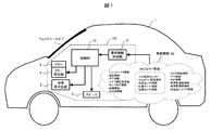
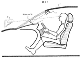
- FIG. 1 is a schematic diagram for explaining the outline of a head up display (hereinafter referred to as HUD) mounted on a vehicle.
- the HUD 100 mounted on the vehicle 1 projects the image light generated by the image display device 2 onto the windshield (hereinafter referred to as a windshield 7) of the vehicle 1 through the mirror 3.
- the image light reflected by the windshield 7 enters the eyes of the driver, and the driver visually recognizes the image from the HUD.
- the video to be displayed includes information related to driving and supports driving operation.
- the HUD 100 includes a vehicle information acquisition unit 5 that acquires various vehicle information 50, a control unit 10 that generates video information to be displayed based on the vehicle information acquisition unit 5, a mirror drive unit 4 that drives the mirror 3, and a driver.
- a speaker 6 for outputting audio information is included.
- the vehicle information 50 includes an operation signal by the driver such as a HUD display On / Off signal and a HUD mirror adjustment signal related to the adjustment of the mirror 3 of the HUD. .
- FIG. 2 is a block diagram showing the internal configuration of the HUD 100.
- Various vehicle information 50 is input to the vehicle information acquisition unit 5 and sent to the control unit 10.
- An electronic control unit (ECU, Electronic Control Unit) 11 in the control unit 10 generates a video signal displayed by the HUD based on the input vehicle information. Moreover, based on vehicle information, the control signal with respect to the mirror 3 and the audio
- the video display device 2 includes a light source 21 such as an LED or a laser, an illumination optical system 22, and a display element 23 such as a liquid crystal element, and emits video light generated by the display element 23 toward the mirror 3.
- an audio output unit 12 that outputs an audio signal to the speaker 6, a non-volatile memory 13 that stores a program executed by the ECU 11, a memory 14 that stores video information and control information, and a light source of the video display device 2 21, a light source adjustment unit 15 that controls 21, a distortion correction unit 16 that corrects distortion of a video signal to be displayed, a display element driving unit 17 that drives the display element 23 based on the corrected video signal, and a mirror driving unit 4.
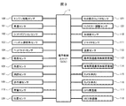
- FIG. 3 is a diagram illustrating an example of a hardware configuration related to the acquisition of the vehicle information 50 in the HUD.
- a part of the hardware configuration of the vehicle information acquisition unit 5 and the control unit 10 will be mainly shown.
- Acquisition of the vehicle information 50 is performed by information acquisition devices, such as various sensors connected to ECU11 under control of ECU11, for example.
- a vehicle speed sensor 101 for example, a vehicle speed sensor 101, a shift position sensor 102, a steering wheel steering angle sensor 103, a headlight sensor 104, an illuminance sensor 105, a chromaticity sensor 106, a distance measuring sensor 107, an infrared sensor 108, an engine start sensor 109, acceleration sensor 110, gyro sensor 111, temperature sensor 112, road-to-vehicle communication wireless receiver 113, vehicle-to-vehicle communication wireless receiver 114, camera (inside the vehicle) 115, camera (outside the vehicle) 116, GPS receiver 117, and VICS (Vehicle Information and Communication System): a device such as a receiver 118, load sensor 119, position sensor 120, HUD display On / Off sensor 121, HUD mirror adjustment sensor 122, etc. Have It is not always necessary to include all these devices, and other types of devices may be included.
- the vehicle information 50 that can be acquired by the equipped device can be used as appropriate.
- the vehicle speed sensor 101 acquires speed information of the vehicle 1.
- the shift position sensor 102 acquires current gear information of the vehicle 1.
- the steering wheel angle sensor 103 acquires steering wheel angle information.
- the headlight sensor 104 acquires lamp lighting information related to On / Off of the headlight.
- the illuminance sensor 105 and the chromaticity sensor 106 acquire external light information.
- the distance measuring sensor 107 acquires distance information between the vehicle 1 and an external object.
- the infrared sensor 108 acquires infrared information related to the presence / absence and distance of an object at a short distance of the vehicle 1.
- the engine start sensor 109 detects engine On / Off information.
- the acceleration sensor 110 and the gyro sensor 111 acquire acceleration gyro information including acceleration and angular velocity as information on the posture and behavior of the vehicle 1.
- the temperature sensor 112 acquires temperature information inside and outside the vehicle.
- the road-to-vehicle communication wireless receiver 113 and the vehicle-to-vehicle communication wireless receiver 114 are respectively road-to-vehicle communication information received by road-to-vehicle communication between the vehicle 1 and roads, signs, signals, etc.
- the vehicle-to-vehicle communication information received by the vehicle-to-vehicle communication with another vehicle is acquired.
- the camera (inside the vehicle) 115 and the camera (outside the vehicle) 116 respectively capture the moving image of the situation inside and outside the vehicle and acquire camera video information (inside / outside the vehicle).
- the camera (inside the vehicle) 115 captures, for example, the driver's posture, eye position, movement, and the like. By analyzing the obtained moving image, for example, it is possible to grasp the driver's fatigue status, the position of the line of sight, and the like.
- the camera (outside the vehicle) 116 captures surrounding conditions such as the front and rear of the vehicle 1. By analyzing the obtained video, for example, it is possible to grasp the presence or absence of moving objects such as other vehicles and people around the building, topography, road surface conditions (rain, snow, freezing, unevenness, etc.) It is.
- the GPS receiver 117 and the VICS receiver 118 obtain GPS information obtained by receiving the GPS signal and VICS information obtained by receiving the VICS signal, respectively. It may be implemented as a part of a car navigation system that acquires and uses these pieces of information.
- the load sensor 119 and the position sensor 120 detect the position / posture of the driver.
- the HUD display On / Off sensor 121 detects whether the HUD power supply is On or Off.
- the HUD mirror adjustment sensor 122 detects an adjustment signal of the HUD mirror and acquires information on whether or not to perform mirror adjustment processing.
- HUD-related sensors may be provided inside the HUD.
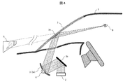
- FIG. 4 is a schematic diagram showing a video display state by HUD.
- Display image light is emitted from the image display device 2 installed at the lower part of the dashboard of the vehicle 1.
- the image light is reflected by the first mirror 3 b and the second mirror 3 a (for example, a concave mirror, a free-form surface mirror, a mirror having an optical axis asymmetric shape, etc.) and projected toward the windshield 7.
- the first mirror 3 b is fixed, and the second mirror 3 a can be rotated by the mirror driving unit 4.
- the second mirror 3a is simply referred to as “mirror 3”.
- the image light converged and projected from the mirror 3 is reflected by the windshield 7, enters the driver's eyes 8, and forms an image on the retina so that the image can be visually recognized.
- the driver sees the virtual image 9 present in front of the windshield 7.
- the reflection position of the image light on the windshield 7 is indicated by reference numeral 70. That is, the driver sees the virtual image 9 in the forward direction of the reflection position 70.
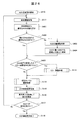
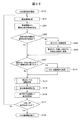
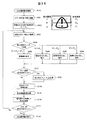
- FIG. 5 is a flowchart showing the basic operation of the HUD.
- (A) shows an initial operation, and (b) shows a normal operation including various adjustments.
- the following processing is controlled by the electronic control unit (ECU) 11 of the control unit 10, and the processing content will be described along the flow.
- ECU electronice control unit
- the vehicle information acquisition unit 5 acquires the vehicle information 50 (S102). First, an appropriate brightness level is calculated from external light information from the illuminance sensor 105 (S103), and the brightness level of the light source 21 is set by controlling the light source adjustment unit 15 (S104). Further, information selected by the driver (for example, current vehicle speed information) is extracted from the acquired vehicle information 50, and an image to be displayed is determined (S105). The distortion correction unit 16 corrects the image distortion generated in the projection optical system (for example, the curved shape of the windshield 7) on the display image (S106).
- the display element drive unit 17 supplies a drive signal to the display element 23 (S107). It is determined whether or not an On signal has been received by the HUD display On / Off sensor 121 (S108) and waits until an On signal is received (S109). When the On signal is received, the light source 21 of the video display device 2 is turned on, and video projection display, that is, normal operation of HUD is started (S110).
- the vehicle information 50 is continuously acquired via the vehicle information acquisition unit 5 (S111). It is determined whether or not a mirror adjustment signal is received from the HUD mirror adjustment sensor 122 (S112), and if received, mirror adjustment processing is performed (S113). In the mirror adjustment processing, the mirror drive unit 4 adjusts the angle of the mirror 3 and the like, which will be described in detail later. Thereafter, a brightness level adjustment process (S114) of the display image and a change process (S115) of the display image are performed, and the display is updated by controlling the display element (S116). The details will be described later.
- FIGS. 6A and 6B are flowcharts showing details of the process of FIG. 5, (a) is a mirror adjustment process (S113), (b) is a brightness level adjustment process (S114), and (c) is a display video change process (S115). ).
- the mirror adjustment unit 18 determines the adjustment amount, and the mirror drive unit 4 moves the mirror 3 in order. It is rotated in the direction (or the reverse direction) (S201). It is determined whether or not the mirror adjustment signal is lost (S202), and the rotation is continued during the period of receiving the signal (S203). When the driver stops the operation and the signal disappears, the rotation operation of the mirror 3 is stopped (S204), and the adjustment process is terminated (S205).
- the rotation direction (forward / reverse) of the mirror 3 in S201 can be selected by the driver. Alternatively, the rotation direction (forward / reverse) may be automatically switched when the rotation end is reached. Thus, the driver can adjust the mirror 3 to an optimum angle while viewing the display image of the HUD.
- an appropriate brightness level is calculated from the current external light information by the illuminance sensor 105 (S211). It is determined whether or not the brightness level needs to be changed (S212). If the change is necessary, the light source adjustment unit 15 is controlled to change and set the brightness level of the light source 21 (S213). This completes the adjustment of the brightness level (S214), and the video is displayed at the changed brightness level thereafter.
- the content of the display video is changed based on the latest vehicle information 50 (S221).
- the display speed is changed based on the current speed information from the vehicle speed sensor, or the guidance arrow display is changed based on the navigation information from the GPS receiver or the VICS receiver.
- the item to be displayed can be selected by the driver, and when the item is changed, the content is switched to the content corresponding to the new item. In this way, the display image based on the latest information is determined and supplied to the display element 23 (S222), and the change process is terminated (S223).
- Example 1 describes an example of a mirror adjustment mechanism of a head-up display (HUD) according to the present invention, but will be described in comparison with a conventional adjustment mechanism for easy understanding.
- HUD head-up display
- FIG. 7 is a diagram for explaining a conventional mirror adjustment method 1.
- the video light emitted from the video display device 2 is reflected by the mirror 3, is reflected by the reflection position 70 of the windshield and enters the driver's eyes 8, and the driver visually recognizes it as a virtual image 9.
- the position of the eye 8 (hereinafter referred to as eye point) changes as A, B, C depending on the height of the driver, the image light emitted from the image display device 2 cannot enter each eye point, or Even if it can be incident, a part of the image may be lost.
- the mirror 3 is rotated by the mirror driving unit 4. According to this, the driver can visually recognize the virtual image 9 by adjusting the rotation position of the mirror 3 as A, B, C corresponding to the eye point of the driver.
- the mirror rotation mechanism since only the mirror rotation mechanism is used in this adjustment method 1, the following phenomenon occurs when the driver visually recognizes the display image. (1) Since the reflection position 70 of the windshield moves like A, B, and C, the position where the driver's line of sight intersects the windshield moves. (2) The angle of the line of sight where the driver looks down on the virtual image 9 (hereinafter referred to as the depression angle) changes. (3) The position of the virtual image 9 visually recognized by the driver moves like A, B, and C.
- the above problem is solved as a configuration in which the mirror driving unit 4 includes not only the mirror rotation mechanism but also the mirror movement mechanism. That is, the mirror moving mechanism can easily move the position of the rotation axis of the mirror in the vertical direction and the front-back direction.
- specific adjustment methods 2, 3, and 4 will be described.
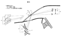
- FIG. 8 is a diagram for explaining the mirror adjustment method 2 according to the present embodiment.
- the problem (1) is addressed, and the reflection position 70 of the windshield is fixed.
- Mirror drive unit 4 can move not only the rotation of mirror 3 but also the rotation axis of the mirror in the vertical direction and the front-rear direction.
- the driver's eye point 8 changes as A, B, C
- the reflection of the windshield is set by combining the rotation and movement of the mirror 3 as shown in FIG.
- the position 70 can be fixed to one position without moving. A specific example of the setting condition will be described later.
- FIG. 9 is a diagram for explaining the mirror adjustment method 3 according to the present embodiment.
- the problem of the above (2) is dealt with and the driver's depression angle is fixed.
- the mirror drive unit 4 moves the mirror 3 to the positions A, B, and C while keeping the rotation angle of the mirror 3 constant as shown in FIG.
- the driver's depression angle ⁇ 1 can be fixed at a constant angle.
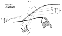
- FIG. 10 is a diagram for explaining the mirror adjustment method 4 according to this embodiment.
- the problem of the above (3) is dealt with, and the position of the virtual image 9 visually recognized by the driver is fixed.
- the driver's visual recognition can be achieved by combining the rotation and movement of the mirror 3 as shown in FIG.
- the position of the virtual image 9 can be fixed. A specific example of the setting condition in this case will also be described later.
- the conventional problems (1), (2), and (3) can be solved by combining the moving mechanism of the mirror 3. Further, the driver can select and implement an appropriate method from the adjustment methods 2 to 4 according to the driving situation and the visibility situation (in that case, the adjustment method 1 may be included as an option).
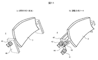
- FIG. 11 is a diagram illustrating an example of an adjustment mechanism of the mirror driving unit 4.
- (A) is the case of the conventional adjustment method 1
- (b) is the case of the adjustment methods 2 to 4 of the present embodiment.
- the mirror driving unit 4 is configured to rotate the mirror 3 by a single rotation motor 40 attached to the fixed arm 49.
- the mirror driving unit 4 rotates and rotates the mirror 3 using the three rotary motors 41, 42, 43 and the two movable arms 44, 45. It is configured to move.
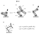
- FIG. 12 is a diagram for explaining the adjustment operation by the adjustment mechanism of FIG.
- the mirror 3 is attached to the rotary motor 43, and the rotary motor 43 is fixed to the housing via a link mechanism including two movable arms 44 and 45 and the rotary motors 41 and 42.
- the height position of the mirror 3 can be lowered as shown in (b) or raised as shown in (c).
- (D) shows the movement position L 3 (x, y) of the mirror 3 by a calculation formula, and the lengths L 1 and L 2 of the movable arms 44 and 45 and the rotation angle ⁇ 1 of the rotary motors 41 and 42, By ⁇ 2 , it can be moved to a desired position.
- the rotation angle of the mirror 3 is given by the rotation angle ⁇ 3 of the rotary motor 43.
- the mirror adjustment mechanism shown here can be realized with a simple structure, the HUD device can be easily mounted on a vehicle without increasing its size.
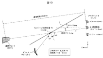
- FIG. 13 is a diagram showing an analysis model of the mirror adjustment mechanism.
- the coordinates (X2, Y2) and the rotation angle ( ⁇ 2) of the mirror 3 are obtained.
- the coordinates (X3, Y3) of the reflection position 70 of the windshield at that time, the center coordinates (X4, Y4) of the virtual image 9 and the depression angle ( ⁇ 1) overlooking the virtual image 9 are calculated.
- the preconditions for the analysis were as follows: the distance to the virtual image 9 was 2000 mm, the inclination angle ⁇ 0 of the windshield 7 was 30 deg, the depression angle ⁇ 1 at the eyepoint reference position (position B) was 8 deg, and the windshield was a flat glass.
- the conditions for the normal viewing of the image at each eye point are that the incident angle ⁇ 1 and the reflection angle ⁇ 2 of the image light at the windshield reflection position 70 are equal and the optical path length r1 + r2 is constant.
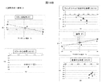
- FIG. 14A and 14B show analysis results in the case of mirror adjustment method 1 (conventional) in FIG.
- the analysis results for each of the eye points A, B, and C are shown as a table in FIG. 14A and as a graph in FIG. 14B.
- the center coordinates (X2, Y2) of the mirror are fixed, and only the rotation angle ( ⁇ 2) of the mirror is changed. Therefore, all of the windshield reflection center coordinates (X3, Y3), the depression angle ( ⁇ 1), and the virtual image center coordinates (X4, Y4) are changed.
- FIG. 15A and 15B show the analysis results in the case of mirror adjustment method 2 (one of the examples) in FIG.
- the analysis results for each of the eye points A, B, and C are shown as a table in FIG. 15A and as a graph in FIG. 15B.
- the center coordinates (X2, Y2) of the mirror and the rotation angle ( ⁇ 2) of the mirror are changed so that the windshield reflection center coordinates (X3, Y3) are constant.
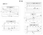
- FIG. 16A and FIG. 16B show the analysis results in the case of the mirror adjustment method 3 (one of the embodiments) of FIG.
- the analysis results for the respective eye points A, B, and C are shown as a table in FIG. 16A and as a graph in FIG. 16B.
- the center coordinates (X2, Y2) of the mirror are changed so that the depression angle ( ⁇ 1) is constant.
- the rotation angle ( ⁇ 2) of the mirror is constant.
- FIG. 17A and FIG. 17B show the analysis results in the case of mirror adjustment method 4 (one of the embodiments) of FIG.
- the analysis results for the respective eye points A, B, and C are represented as a table in FIG. 17A and as a graph in FIG. 17B.
- the mirror center coordinates (X2, Y2) and the mirror rotation angle ( ⁇ 2) are changed so that the virtual image center coordinates (X4, Y4) are constant.
- the mirror adjustment unit 18 stores the adjustment amount of the center coordinates (X2, Y2) and the rotation angle ( ⁇ 2) corresponding to each position of the eye point in each adjustment method in association with each other, and this relationship is stored. Make adjustments while keeping.
- the optimal adjustment amount (coordinates and rotation angle) of the mirror is determined by the driver while viewing the display image. That is, the mirror adjustment unit 18 acquires an operation signal from the driver from the HUD mirror adjustment sensor 122, and determines the end point of the adjustment operation.
- the mirror can be adjusted so that the windshield reflection position and the virtual image position do not move even if the driver's eye position changes, the driver can view the image more preferably without a sense of incongruity. it can. Since the mirror adjustment mechanism used for this can be realized with a simple structure, it can be easily mounted on a vehicle without increasing the size of the apparatus.
- Example 1 the optimum position for mirror adjustment was determined by the driver looking at the video, that is, the manual adjustment method.
- the position of the driver's eyes is calculated, and the mirror position is automatically adjusted to the optimum state accordingly.
- the center of gravity position of the driver is obtained from the driver position and load, and the eye position is calculated from the center of gravity position.
- the mirror adjustment mechanism employs each adjustment method described in the first embodiment, and the mirror driving unit 4 is configured to adjust the coordinate and the rotation angle of the mirror in conjunction with each other.
- FIG. 18 is a diagram showing examples of various sensors in the vehicle used for automatic mirror adjustment.
- load sensors load cell, displacement sensor, etc.
- the position sensor 120 for detecting the position of the driver is provided on a headrest (height position) 120a, a back surface (tilt) 120b, and a seat surface (front-rear position) 120c.
- the center-of-gravity calculation unit 19 in the control unit 10 calculates the driver's driving posture and physique information (height and weight), and derives the driver's center-of-gravity position 65 and the position of the eye point 8.
- the relationship between the center of gravity position 65 and the eye point 8 is estimated based on the physique information.
- the mirror adjusting unit 18 calculates the mirror adjustment amount and optimally adjusts the position and angle of the mirror 3 via the mirror driving unit 4 as described in the first embodiment. Since the mirror adjustment unit 18 stores in advance the optimum adjustment amount (coordinates and rotation angle) of the mirror corresponding to each position of the eye point 8, the mirror can be automatically adjusted to the optimum state. Further, during driving, the driver's center of gravity is monitored, and if the center of gravity shifts, it is determined that the eye point position has also changed, and the mirror is automatically corrected so as to follow this state.
- the shift direction of the center of gravity that is, the shift direction of the eye point can be not only the height direction but also the front-rear direction and the left-right direction as viewed from the driver.
- the mirror can be optimally adjusted with respect to the change in the front-rear direction.
- FIG. 19 is a flowchart showing the automatic mirror adjustment operation. (A) shows initial adjustment, and (b) shows adjustment during operation.
- the detection result is acquired from the load sensor 119 via the vehicle information acquisition unit 5 (S301), and the detection result is acquired from the position sensor 120 (S302).
- the center-of-gravity calculation unit 19 of the control unit 10 calculates the height and weight of the driver from these detection results (S303), and calculates the center-of-gravity position 65 and the eye point 8 position (S304).
- the calculated value is stored as an initial value.
- the mirror adjustment unit 18 calculates a mirror adjustment amount according to the calculated eye point position, and optimally adjusts the position and angle of the mirror 3 via the mirror drive unit 4 (S305). Thereafter, the process proceeds to the HUD normal operation (S306).
- the center of gravity calculation unit 19 monitors the center of gravity position of the driver and monitors the change of the center of gravity position from the initial value (S311).
- the mirror adjustment unit 18 calculates a mirror adjustment amount corresponding to the movement amount ( S314), the position and angle of the mirror 3 are adjusted via the mirror drive unit 4 (S315). If the center of gravity moves in the left-right direction (Yes in S316), the distortion correction unit 16 performs image distortion correction (S317). Thereafter, the flow returns to the center-of-gravity position monitoring (S311) and the above flow is repeated.
- the driver's line-of-sight position is detected by image recognition, but the detection accuracy depends on the surrounding environment, weather, and the like. In particular, under dark conditions during night driving, the detection accuracy is extremely lowered due to a decrease in the amount of light and contrast in the vehicle, and the tracking performance is deteriorated. In general, the line of sight is frequently moved during driving. However, if mirror adjustment is performed by following this movement, the driver may be adversely affected such as eye fatigue or sickness.
- the position of the driver's center of gravity is calculated using a load sensor, a position sensor, etc., and follow-up control is performed according to the movement of the center of gravity. Therefore, the detection value is stable and the display image is stable, so that the driver does not feel uncomfortable.
- the configuration in which the video display area is mainly moved in the vertical direction according to the position (eye point) of the driver has been described.
- a configuration for moving the video display area in the left-right direction will be described.
- Example 3 describes a configuration in which the entire HUD is moved left and right in the dashboard in order to move the video display area in the left and right direction.
- the display area needs to be moved in the left-right direction, for example, in the following cases.
- (1) When the driver's eye position (eye point) moves in the left-right direction.
- (2) When the driver's posture (center of gravity position) moves in the left-right direction.
- (3) When the vehicle traveling direction changes according to the driving operation (the steering wheel operation or the direction indicator).
- the driver's line of sight changes according to road guidance (right / left turn sign or intersection distance).
- (5) When the driver's line of sight changes due to an obstacle (interrupt car or jumping pedestrian).
- the change in the situation is acquired as vehicle information by an information acquisition device (such as various sensors) mounted on the vehicle, and the control unit of the HUD is configured to automatically display an image at an optimal position.
- an information acquisition device such as various sensors
- FIG. 20 is a block diagram showing the internal configuration of the head-up display 100a.
- a function for moving the entire HUD 100a to the left and right is added.
- FIG. 20 in relation to Examples 4 and 5 to be described later, a case where the image display device 2 is installed on the roof of the vehicle for projection, and a dimming mirror 30 capable of switching between reflection / non-reflection as the mirror 3. It includes the case where is used.
- the functions added to the configuration of FIG. 2 are as follows.
- the HUD position adjusting unit 24 determines the moving position of the HUD 100 a and sends a control signal to the HUD driving unit 25.
- the HUD drive unit 25 has a rail guide and a drive motor, as will be described later, and moves the HUD 100a to the left and right.
- the projection angle adjustment unit 26 determines the projection direction (projection angle) when the video display device 2 is installed on the roof of the vehicle, and the projection angle drive unit 27 changes the direction of the projection unit of the video display device 2.
- the dimming mirror control unit 28 When the dimming mirror 30 is used, the dimming mirror control unit 28 generates a reflection / non-reflection switching signal for the dimming mirror 30, and the dimming mirror voltage supply unit 29 applies a predetermined voltage to the dimming mirror 30. Is applied to switch between the mirror surface state (ON state) and the transparent state (OFF state).
- FIG. 21 is a block diagram illustrating an example of a hardware configuration related to the acquisition of the vehicle information 50.
- a direction indicator sensor 123 is added to the configuration of FIG.
- the following sensor is used. (1) Driver's eye position ...
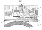
- FIG. 22 is a diagram showing an example of a video display state viewed from the driver's seat.
- An image in this example, a vehicle speed value “60 km / h” is displayed through the windshield 7 so as to overlap the scenery in front.
- This display position (that is, the reflection position 70 on the windshield 7) is moved in the left-right direction in conjunction with the operation of the handle 73, for example.
- the HUD 100 a housed in the lower part of the dashboard 71 is configured to be movable left and right along the driving groove 72.
- FIG. 23 is a cross-sectional view in the vehicle showing the video display operation.
- a groove 72 is formed in the dashboard 71 to accommodate the HUD 100a.
- the HUD 100 a can be moved in the drawing depth direction along the groove 72 by the HUD driving unit 25.
- the image light projected from the HUD 100 a is reflected by the windshield 7 (reflection position 70) and enters the driver's eyes 8, so that the driver sees the virtual image 9 in front of the reflection position 70.
- FIG. 24 is a top view in the vehicle showing the video display operation.
- the HUD driving unit 25 By moving the position of the HUD 100a in the left-right direction by the HUD driving unit 25 (using a driving belt here), the reflection position 70 of the image viewed from the eyes 8 of the driver, that is, the position of the front virtual image 9 is moved. As shown in FIG. 22, the image display position can be moved in the left-right direction.
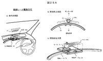
- FIG. 25A and FIG. 25B are diagrams showing a specific drive mechanism of the HUD drive unit 25 in two ways.
- FIG. 25A shows the case of the curved rail drive system, in which (a) is a perspective view inside the vehicle, (b) is a top view of the drive unit, and (c) is an enlarged view of the drive unit.
- the HUD 100a is fixedly mounted on the moving table 79, and the moving table 79 moves in the left-right direction along the curved rail 74 by the driving force of the motor 75 attached to the table.
- the driving force of the motor 75 is transmitted to a directly connected driving roller (driving gear), and the moving table 79 is caused to travel by meshing with the gear of the curved rail 74.
- the projection direction (left-right angle) of the HUD 100a is simultaneously changed according to the curvature, and an image is displayed at an optimum projection angle as seen from the driver seat according to the left-right movement position.
- the type of the motor 75 is not particularly limited, but a stepping motor or a servo motor is suitable.
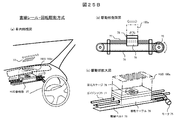
- FIG. 25B shows the case of the linear rail + rotation drive system, where (a) is a perspective view inside the vehicle, (b) is a side view of the drive unit, and (c) is an enlarged view of the drive unit.
- the HUD 100a is mounted on a moving table 79 via a rotary stage 78.
- the moving table 79 is moved in the left-right direction along a linear guide shaft 77 by a motor 75 and a drive belt 76.
- the moving table 79 is fixed at a predetermined position on the driving belt 76, and the driving belt 76 is between a driving roller (or pulley) for transmitting the driving force of the motor 75 and a driven roller (or pulley) installed on the opposite side.
- Reciprocate at The rotary stage 78 is for changing the projection direction of the HUD 100a, and can thereby display an image with an optimal projection angle in accordance with the horizontal movement position of the HUD 100a.
- the motor 75 is not particularly limited, but a stepping motor or a servo motor is suitable.
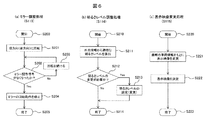
- FIG. 26 is a flowchart showing the display area moving operation by adjusting the HUD position. A process for adjusting the HUD position is added based on the normal operation of the HUD in FIG.
- a case where the display area is moved in conjunction with the handle operation will be described as an example.
- the HUD position adjusting unit 24 calculates an appropriate HUD position according to the steering angle information. For this reason, an appropriate display position (ie, HUD position) with respect to the direction and size of the steering angle is determined in advance. As an example, the amount of movement of the display position in the left-right direction is set to be substantially proportional to the magnitude of the steering angle.
- the HUD position adjustment unit 24 determines whether or not the current HUD position is an appropriate HUD position. If it is an appropriate position, the process proceeds to S405, and if it is different from the appropriate position, the process proceeds to S403 to perform HUD position adjustment processing.
- the HUD drive unit 25 moves the HUD to an appropriate position, and also adjusts the projection direction according to the HUD position.
- the distortion correction setting corresponding to the moved HUD position is updated. In this case, distortion occurs in the video viewed from the driver as the display position moves to the left and right, so the setting of the video correction processing by the distortion correction unit 16 is changed.
- the video display area moves to the left and right according to the position of the driver's eyes and the driving situation.
- Example 4 also moves the image display area in the left-right direction, but the image display device with a variable projection direction is installed on the roof inside the vehicle, and the mirror installed on the dashboard is moved left and right.
- FIG. 27 is a diagram showing an example of a video display state viewed from the driver's seat.
- the video display device 2 is installed on the roof and has a configuration in which the projection direction can be changed to the left and right.
- the mirror 3 that receives the image projection light from the image display device 2 is moved by the mirror drive belt 46.
- the moving position of the mirror 3 is linked with the projection direction of the video display device 2. Thereby, the reflection position 70 of an image
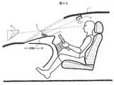
- FIG. 28 is a cross-sectional view in the vehicle showing the video display operation.
- the video display device 2 is installed on the roof, and the projection angle driving unit 27 changes the projection direction.
- the mirror 3 on the dashboard 71 is configured to be moved in the depth direction of the drawing by a mirror driving belt 46 that is one mechanism of the mirror driving unit 4. Thereby, the display position of the virtual image 9 can be moved in the left-right direction.
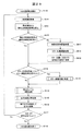
- FIG. 29 is a flowchart showing the display area moving operation by adjusting the projection angle and the mirror position. Steps for adjusting the projection angle and mirror position are added to the normal HUD operation of FIG.
- the case where the display area is moved in conjunction with the handle operation will be described as an example.
- the projection angle adjusting unit 26 calculates an appropriate video projection angle of the video display device 2 according to the steering angle information. Therefore, an appropriate image projection angle with respect to the direction and size of the steering angle is determined in advance.
- the projection angle adjustment unit 26 determines whether or not the current video projection angle is an appropriate video projection angle. If it is an appropriate projection angle, the process proceeds to S416. If it is different from the appropriate projection angle, the process proceeds to S413, and the projection angle and mirror position adjustment processing is performed.
- the video display device 2 installed on the roof is rotated by the projection angle driving unit 27 so that the video projection direction is adjusted to an appropriate projection angle.
- the mirror 3 is moved to a position corresponding to the projection direction by the mirror driving unit 4 (mirror driving belt 46) in accordance with the change of the projection angle.
- the distortion correction setting corresponding to the moved mirror position is updated. In this case, distortion occurs in the video viewed from the driver as the display position moves to the left and right, so the setting of the video correction processing by the distortion correction unit 16 is changed.
- mirror adjustment processing (angle adjustment) is performed in S113. This is because, as the mirror position moves, the relationship between the image projection angle with respect to the windshield 7 and the curvature of the reflecting surface changes, so the elevation angle of the display image viewed from the driver may change. In order to make this elevation angle constant, the angle in the vertical direction of the mirror is adjusted.
- the mirror drive mechanism may be provided with a gradient in the front-rear direction and the gradient may be used to absorb the change in the elevation angle of the display image accompanying the mirror movement. Since S114 and subsequent steps are the same as those in FIG.
- the projection angle adjusting unit 26 first determines the video projection angle of the video display device 2 according to the steering angle, and the mirror driving unit 4 moves the mirror 3 in accordance with the video projection angle.
- the movement position of the mirror 3 may be determined first by the mirror adjustment unit 4 according to the steering angle, and the projection angle driving unit 27 may change the image projection angle accordingly.
- the change of the steering angle of the steering wheel has been described as an example of moving the image display area in the left-right direction, but it goes without saying that the present invention can be similarly applied to any change in the states (1) to (5). .
- the configuration becomes simple and the moving speed of the display position is improved.
- Example 5 also moves the video display area in the left-right direction, but a video display device with a wide viewing angle is installed on the roof inside the vehicle, and a plurality of dimming mirrors are arranged on the dashboard in the left-right direction, It was set as the structure which switches the reflection / non-reflection state of each light control mirror.
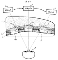
- FIG. 30 is a diagram illustrating an example of a video display state viewed from the driver's seat.
- the video display device 2 having a wide viewing angle is installed on the roof, and a plurality of light control mirrors 30 are arranged on the dashboard 71 in the left-right direction. Since the video display device 2 has display characteristics with a wide viewing angle, it is possible to irradiate the video mirrors 30 with video light simultaneously.
- an image is displayed at the position of the dimming mirror 30 in the reflective state (ON state), but no image is displayed at the position of the dimming mirror 30 in the non-reflecting state (OFF state).
- the dimming mirror 30 By selecting the dimming mirror 30 to be in the reflection state (ON state), the image reflection position 70 can be moved in the left-right direction.
- FIG. 31 is a cross-sectional view in the vehicle showing the video display operation.
- the wide viewing angle video display device 2 is installed on the roof, and a plurality of light control mirrors 30 are arranged on the dashboard 71 in the depth direction of the drawing.
- the dimming mirror control unit 28 moves the display position of the virtual image 9 in the left-right direction by selecting the dimming mirror 30 to be reflected (ON state) and applying a predetermined voltage by the dimming mirror voltage supply unit 29. Can be made.
- FIG. 32 is a flowchart showing a display area moving operation by switching the reflection / non-reflection state of the light control mirror. A step for switching the dimming mirror is added to the normal operation of the HUD in FIG.
- the case where the display area is moved in conjunction with the handle operation will be described as an example.
- the dimming mirror control unit 28 calculates an appropriate video display area corresponding to the steering angle information. Therefore, an appropriate video display area for the direction and size of the steering angle is determined in advance.
- the dimming mirror control unit 28 determines whether or not the current video display area (the position of the dimming mirror in the ON state) is an appropriate display area. If it is an appropriate display area, the process proceeds to S425, and if it is different from the appropriate display area, the process proceeds to S423 to perform switching processing of the light control mirror 30.
- the dimming mirror voltage supply unit 29 applies a predetermined voltage to the dimming mirror 30 corresponding to the appropriate display area to switch to the reflection state (ON state), and other dimming
- the mirror 30 is switched to a non-reflective state (OFF state).
- the distortion correction setting corresponding to the dimming mirror switched to the ON state is updated. In this case, distortion occurs in the video viewed from the driver as the display position moves to the left and right, so the setting of the video correction processing by the distortion correction unit 16 is changed.
- mirror adjustment processing (angle adjustment) is performed in S113. This is because the relationship between the image projection angle with respect to the windshield 7 and the curvature of the reflecting surface changes as the dimming mirror position in the ON state moves, so that the elevation angle of the display image viewed from the driver changes. There is. In order to make this elevation angle constant, the angle in the vertical direction of the dimming mirror is adjusted. When arranging the plurality of dimming mirrors 30, a change in the elevation angle of the display image associated with mirror switching may be absorbed by providing a gradient in the front-rear direction according to the position of each mirror. Since S114 and subsequent steps are the same as those in FIG.
- the change of the steering angle of the steering wheel has been described as an example of moving the image display area in the left-right direction, but it goes without saying that the present invention can be similarly applied to any change in the states (1) to (5). .
- the HUD configuration becomes simpler and the display position can be switched at high speed.
- Example 6 describes a configuration for expanding a display area.
- the size of the area in which video can be displayed by one HUD is limited by the size of the mirror.
- the display area is enlarged by displaying an image while moving the mirror at high speed.
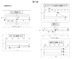
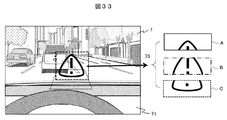
- FIG. 33 is a diagram illustrating an example of a video display state viewed from the driver's seat.
- Video light is emitted from the HUD installed at the lower part of the dashboard 71 and displayed at the reflection position 70 of the windshield 7.
- a plurality of partial images A, B, and C are alternately displayed while being shifted in the vertical direction at the reflection position 70, so that the display area is expanded as compared with the case where a single image (for example, only the image B) is displayed. be able to.
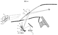
- FIG. 34 is a cross-sectional view in the vehicle showing the video display operation.
- the image light emitted from the image display device 2 is reflected at the reflection position 70 of the mirror 3 and the windshield, and the driver visually recognizes the image as a virtual image 9.
- the mirror driving unit 4 displays the mirror 3 while rotating the mirror 3 by a predetermined angle ⁇ , whereby the reflection position 70 and the display position of the virtual image 9 can be shifted up and down like A, B, and C.
- the corresponding partial images A, B, and C shown in FIG. 33 are displayed in synchronization with the rotation position of the mirror (that is, the display positions A, B, and C).
- the rotational position of the mirror may be controlled in synchronization with the timing of generating the partial images A, B, and C.
- the partial images A, B, and C can be generated by changing the vertical cutout position (drawing start position) with respect to the entire image.
- Mirror movement by the mirror drive unit 4 may be reciprocation between A and C or rotational movement in one direction, but in the case of a moving image, it is moved at high speed so as to follow the changing speed. Further, when the movement of the mirror is a continuous movement, the effective display time (duty ratio) is shortened because the image is displayed only at the timing when the rotation position of the mirror coincides with the display position of each partial image. Therefore, in order to lengthen the effective display time, the movement of the mirror is preferably intermittent movement (step feed) instead of continuous movement.
- FIG. 35 is a flowchart showing an enlarged image display operation by mirror movement. A process of mirror movement and display image switching is added to the HUD normal operation of FIG.
- the mirror driving unit 4 starts reciprocating (or rotating) movement of the mirror 3.
- the mirror motion is a continuous motion.
- the display element driving unit 17 determines a division specification (for example, division into partial images A, B, and C) of the display image, and the mirror adjustment unit 18 uses a mirror angle for displaying the partial images A, B, and C.
- ⁇ A , ⁇ B , and ⁇ C are set and stored in the memory 14.
- the current mirror angle ⁇ is acquired from the mirror driving unit 4, and in S504, the mirror adjusting unit 18 compares the current mirror angle ⁇ with the display angles ⁇ A , ⁇ B , and ⁇ C. If the current mirror angle ⁇ is different from any of the display angles ⁇ A , ⁇ B , and ⁇ C as a result of the comparison, the process proceeds to S505, and the display element driving unit 17 outputs a black image to the video display device 2.
- the light source 21 may be turned off by the light source adjustment unit 15.
- the process proceeds to S506, where the display element driving unit 17 cuts out the partial image A, outputs it to the video display device 2, and displays it.
- the process proceeds to S507, the display is cut out partial image B. If the current mirror angle ⁇ matches the display angle ⁇ C , the process proceeds to S508, where the partial image C is cut out and displayed.
- the partial images A, B, and C can be alternately displayed, and as a result, the entire image can be displayed. According to the present embodiment, it is possible to display a large screen image by enlarging the display area of the image while using one HUD.
- the present invention is not limited to the above-described embodiments, and includes various modifications.
- a part of the configuration of one embodiment can be replaced with the configuration of another embodiment, and the configuration of another embodiment can be added to the configuration of one embodiment.
Landscapes
- Engineering & Computer Science (AREA)
- Physics & Mathematics (AREA)
- General Physics & Mathematics (AREA)
- Computer Hardware Design (AREA)
- Theoretical Computer Science (AREA)
- Optics & Photonics (AREA)
- Chemical & Material Sciences (AREA)
- Combustion & Propulsion (AREA)
- Transportation (AREA)
- Mechanical Engineering (AREA)
- Instrument Panels (AREA)
Abstract
L'invention concerne un dispositif d'affichage d'image pour un véhicule qui peut rendre une image visible de manière appropriée par une structure simple, même si la position des yeux du conducteur change. Un dispositif d'affichage d'image (100) pour un véhicule comprend : une unité d'affichage d'image (2) qui comprend une source de lumière et un élément d'affichage et qui émet une lumière d'image ; un miroir (3) qui réfléchit la lumière d'image émise par l'unité d'affichage d'image (2) vers un pare-brise (7) ; une unité d'entraînement de miroir (4) qui change l'angle et la position du miroir (3) ; et une unité de commande (10) qui détermine des quantités de changement de l'angle et de la position du miroir et commande l'unité d'entraînement de miroir (4). L'unité de commande (10) réalise des déterminations de la quantité de changement de l'angle et de la position du miroir en association les unes avec les autres de telle sorte que l'image est visible même si la position des yeux (8) du conducteur change et l'état d'affichage de l'image par rapport au conducteur ne change pas.
Priority Applications (4)
| Application Number | Priority Date | Filing Date | Title |
|---|---|---|---|
| JP2017566536A JP6527605B2 (ja) | 2016-02-12 | 2016-12-12 | 車両用映像表示装置 |
| US18/081,853 USRE50118E1 (en) | 2016-02-12 | 2016-12-12 | Image display apparatus for vehicle |
| US16/068,985 US10871655B2 (en) | 2016-02-12 | 2016-12-12 | Image display apparatus for vehicle |
| CN201680071335.XA CN108292045B (zh) | 2016-02-12 | 2016-12-12 | 车辆用影像显示装置 |
Applications Claiming Priority (4)
| Application Number | Priority Date | Filing Date | Title |
|---|---|---|---|
| JP2016-024711 | 2016-02-12 | ||
| JP2016024711 | 2016-02-12 | ||
| JP2016071034 | 2016-03-31 | ||
| JP2016-071034 | 2016-03-31 |
Publications (1)
| Publication Number | Publication Date |
|---|---|
| WO2017138242A1 true WO2017138242A1 (fr) | 2017-08-17 |
Family
ID=59562990
Family Applications (1)
| Application Number | Title | Priority Date | Filing Date |
|---|---|---|---|
| PCT/JP2016/086914 Ceased WO2017138242A1 (fr) | 2016-02-12 | 2016-12-12 | Dispositif d'affichage d'image pour véhicule |
Country Status (4)
| Country | Link |
|---|---|
| US (2) | US10871655B2 (fr) |
| JP (1) | JP6527605B2 (fr) |
| CN (1) | CN108292045B (fr) |
| WO (1) | WO2017138242A1 (fr) |
Cited By (25)
| Publication number | Priority date | Publication date | Assignee | Title |
|---|---|---|---|---|
| CN108459415A (zh) * | 2018-03-28 | 2018-08-28 | 京东方科技集团股份有限公司 | 一种平视显示器、平视显示方法以及车辆 |
| JP2019012191A (ja) * | 2017-06-30 | 2019-01-24 | 株式会社Jvcケンウッド | 虚像表示装置 |
| JP2019038342A (ja) * | 2017-08-23 | 2019-03-14 | 日本精機株式会社 | 画像処理ユニット及びそれを備えるヘッドアップディスプレイ装置 |
| JP2019064513A (ja) * | 2017-10-03 | 2019-04-25 | 株式会社デンソー | 虚像表示装置 |
| WO2019224922A1 (fr) * | 2018-05-22 | 2019-11-28 | 三菱電機株式会社 | Dispositif de commande d'affichage tête haute, système d'affichage tête haute et procédé de commande d'affichage tête haute |
| JPWO2021015171A1 (fr) * | 2019-07-25 | 2021-01-28 | ||
| JP2021015166A (ja) * | 2019-07-10 | 2021-02-12 | マクセル株式会社 | ヘッドアップディスプレイ及びそのキャリブレーション方法 |
| JP2021047234A (ja) * | 2019-09-17 | 2021-03-25 | 株式会社小糸製作所 | 画像表示装置 |
| WO2021065698A1 (fr) * | 2019-09-30 | 2021-04-08 | 日本精機株式会社 | Dispositif d'affichage tête haute, procédé et programme d'ordinateur |
| WO2021079741A1 (fr) * | 2019-10-21 | 2021-04-29 | マクセル株式会社 | Dispositif de source de lumière, système d'affichage d'informations et appareil d'affichage tête haute l'utilisant |
| CN113424094A (zh) * | 2018-10-10 | 2021-09-21 | 纳宝实验室株式会社 | 利用挡风玻璃反射方式使虚拟影像位于地面的三维增强现实平视显示器 |
| WO2022024814A1 (fr) * | 2020-07-28 | 2022-02-03 | 京セラ株式会社 | Système de caméra et système d'aide à la conduite |
| CN115461671A (zh) * | 2020-04-30 | 2022-12-09 | 京瓷株式会社 | 图像显示系统 |
| JP2023072377A (ja) * | 2021-11-12 | 2023-05-24 | キヤノン株式会社 | 虚像光学系、それを備える虚像表示装置及び車載システム |
| WO2023100785A1 (fr) * | 2021-11-30 | 2023-06-08 | 日本精機株式会社 | Dispositif d'affichage tête haute |
| WO2023218773A1 (fr) * | 2022-05-09 | 2023-11-16 | マクセル株式会社 | Appareil d'affichage tête haute |
| WO2023233737A1 (fr) * | 2022-06-03 | 2023-12-07 | 日亜化学工業株式会社 | Système d'affichage vidéo |
| WO2023238460A1 (fr) * | 2022-06-08 | 2023-12-14 | 日亜化学工業株式会社 | Unité de source de lumière et appareil d'affichage vidéo |
| WO2023243297A1 (fr) * | 2022-06-14 | 2023-12-21 | 矢崎総業株式会社 | Appareil d'affichage pour véhicule |
| EP3876529B1 (fr) * | 2018-11-02 | 2024-03-27 | Kyocera Corporation | Système d'affichage tête haute de communication, dispositif de communication, corps mobile, et programme |
| WO2024105899A1 (fr) * | 2022-11-17 | 2024-05-23 | マクセル株式会社 | Dispositif d'affichage tête haute et véhicule |
| US12158580B2 (en) | 2022-12-05 | 2024-12-03 | Nichia Corporation | Light source unit and image display device |
| CN119636407A (zh) * | 2025-01-03 | 2025-03-18 | 奇瑞汽车股份有限公司 | 一种随动hud系统、车辆及方法 |
| US12265220B2 (en) | 2022-11-15 | 2025-04-01 | Nichia Corporation | Image display device |
| US12535680B2 (en) | 2022-12-26 | 2026-01-27 | Nichia Corporation | Light source unit and image display device |
Families Citing this family (42)
| Publication number | Priority date | Publication date | Assignee | Title |
|---|---|---|---|---|
| WO2017064797A1 (fr) * | 2015-10-15 | 2017-04-20 | 日立マクセル株式会社 | Dispositif d'affichage d'informations |
| RU2705742C1 (ru) * | 2016-07-18 | 2019-11-11 | Сэн-Гобэн Гласс Франс | Система индикации на лобовом стекле для отображения визуальной информации и ее калибровка |
| JP2019061559A (ja) * | 2017-09-27 | 2019-04-18 | 本田技研工業株式会社 | 表示装置、表示制御装置及び車両 |
| JP6979617B2 (ja) * | 2017-09-29 | 2021-12-15 | パナソニックIpマネジメント株式会社 | 輝度調整システム、表示システム、移動体、及びプログラム |
| KR102366242B1 (ko) * | 2017-12-07 | 2022-02-23 | 삼성전자주식회사 | 미러 디스플레이 시스템에서 객체의 깊이를 제어하기 위한 방법 |
| JP7140504B2 (ja) * | 2018-02-14 | 2022-09-21 | 矢崎総業株式会社 | 投影表示装置 |
| EP3570089A1 (fr) * | 2018-05-11 | 2019-11-20 | Yazaki Corporation | Afficheur de véhicule |
| KR102540923B1 (ko) * | 2018-07-18 | 2023-06-07 | 현대자동차주식회사 | 차량, 헤드업 디스플레이 장치 및 그 제어 방법 |
| JP6947705B2 (ja) * | 2018-08-07 | 2021-10-13 | 本田技研工業株式会社 | 表示装置、表示制御方法、およびプログラム |
| JP7012618B2 (ja) * | 2018-08-07 | 2022-01-28 | 本田技研工業株式会社 | 表示装置、表示制御方法、およびプログラム |
| DE112020000507T5 (de) * | 2019-01-25 | 2021-11-18 | Nippon Seiki Co., Ltd. | Head-Up-Display-Vorrichtung |
| CN109889805A (zh) * | 2019-02-19 | 2019-06-14 | 上海理工大学 | 一种具有眼球追踪功能的夜视抬头显示设备 |
| CN112053445B (zh) * | 2019-06-06 | 2025-07-29 | 厦门雅迅智联科技股份有限公司 | Ar图像的绘制方法、存储介质 |
| KR102297202B1 (ko) * | 2019-07-23 | 2021-09-01 | 엘지전자 주식회사 | 차량용 표시 장치 |
| CN112744158B (zh) * | 2019-10-30 | 2024-08-09 | 松下汽车电子系统株式会社 | 显示系统 |
| JP7102384B2 (ja) * | 2019-10-31 | 2022-07-19 | 矢崎総業株式会社 | 車両用表示装置 |
| KR20210054107A (ko) * | 2019-11-04 | 2021-05-13 | 현대자동차주식회사 | 차량의 디스플레이 장치 및 방법 |
| US11308921B2 (en) * | 2019-11-28 | 2022-04-19 | Panasonic Intellectual Property Management Co., Ltd. | Information display terminal |
| CN112946888B (zh) * | 2019-12-11 | 2025-11-18 | 未来(北京)黑科技有限公司 | 抬头显示设备、成像系统、车辆、控制方法和装置 |
| CN118091957A (zh) * | 2020-02-28 | 2024-05-28 | 麦克赛尔株式会社 | 平视显示器装置 |
| CN113448086A (zh) | 2020-03-25 | 2021-09-28 | 光宝电子(广州)有限公司 | 可调整成像位置的抬头显示器 |
| CN115280215B (zh) * | 2020-03-25 | 2025-09-19 | 日本精机株式会社 | 平视显示装置、显示控制装置、以及显示控制方法 |
| EP4153455B1 (fr) * | 2020-05-22 | 2025-07-09 | Magna Electronics Inc. | Système et procédé d'affichage |
| CN111596460A (zh) * | 2020-06-29 | 2020-08-28 | 京东方科技集团股份有限公司 | 抬头显示系统 |
| CN111896024A (zh) * | 2020-07-24 | 2020-11-06 | 北京汽车股份有限公司 | 导航显示的控制方法、装置及ar-hud显示系统 |
| CN112114427A (zh) * | 2020-09-08 | 2020-12-22 | 中国第一汽车股份有限公司 | Hud投影高度的调节方法、装置、设备及车辆 |
| JP7517130B2 (ja) * | 2020-12-14 | 2024-07-17 | 株式会社Jvcケンウッド | 表示装置 |
| US12344092B2 (en) * | 2021-02-09 | 2025-07-01 | Hyundai Mobis Co., Ltd. | Smart mobility vehicle |
| JP7767738B2 (ja) * | 2021-06-01 | 2025-11-12 | マツダ株式会社 | ヘッドアップディスプレイ装置 |
| JP7524836B2 (ja) * | 2021-06-10 | 2024-07-30 | トヨタ自動車株式会社 | 車両用表示装置、表示方法及びプログラム |
| US11467415B1 (en) * | 2021-07-21 | 2022-10-11 | GM Global Technology Operations LLC | Viewer input-based control in a multi-image augmented reality head up display system in a vehicle |
| KR20230021487A (ko) * | 2021-08-05 | 2023-02-14 | 현대자동차주식회사 | 차량용 헤드램프의 레벨링 장치 |
| US11662811B2 (en) * | 2021-08-11 | 2023-05-30 | GM Global Technology Operations LLC | Holographic display system |
| CN115840331B (zh) * | 2021-09-18 | 2026-01-02 | 上海汽车集团股份有限公司 | 汽车智显装置、汽车以及汽车智显的控制方法 |
| KR20230046566A (ko) | 2021-09-30 | 2023-04-06 | 삼성전자주식회사 | 룩 다운 앵글의 변화에 대한 시차 광학 소자의 캘리브레이션 장치 및 방법 |
| JP7746807B2 (ja) * | 2021-10-28 | 2025-10-01 | セイコーエプソン株式会社 | 回路装置及びヘッドアップディスプレイ装置 |
| CN117075745A (zh) * | 2022-05-10 | 2023-11-17 | 比亚迪股份有限公司 | 车内影音系统及其交互控制方法、电子设备和车辆 |
| US20230393396A1 (en) * | 2022-06-02 | 2023-12-07 | Harman International Industries, Incorporated | Automatic eye height adjustment |
| EP4303056B1 (fr) * | 2022-07-07 | 2025-11-12 | Bayerische Motoren Werke Aktiengesellschaft | Procédé et système de commande d'un dispositif d'affichage dans un véhicule |
| CN115268086B (zh) * | 2022-09-28 | 2023-03-28 | 合肥疆程技术有限公司 | 一种挡位标定方法及系统、控制装置 |
| US12546997B2 (en) * | 2023-12-22 | 2026-02-10 | E-Lead Electronic Co., Ltd. | Head up display device that utilizes a backlight toroidal mirror to adjust an eye box |
| CN119261547A (zh) * | 2024-09-30 | 2025-01-07 | 小米汽车科技有限公司 | 显示器系统、方法、车辆、存储介质及程序产品 |
Citations (4)
| Publication number | Priority date | Publication date | Assignee | Title |
|---|---|---|---|---|
| JP2003039981A (ja) * | 2001-07-26 | 2003-02-13 | Yazaki Corp | 車載用ヘッドアップディスプレイ装置 |
| JP2010230157A (ja) * | 2009-02-18 | 2010-10-14 | Nippon Seiki Co Ltd | 動力伝達装置 |
| JP2011152883A (ja) * | 2010-01-28 | 2011-08-11 | Toyota Motor Corp | 撮像装置 |
| JP2015225119A (ja) * | 2014-05-26 | 2015-12-14 | 株式会社デンソー | ヘッドアップディスプレイ装置 |
Family Cites Families (12)
| Publication number | Priority date | Publication date | Assignee | Title |
|---|---|---|---|---|
| JPH0626433Y2 (ja) * | 1987-02-23 | 1994-07-20 | 日産自動車株式会社 | ヘツドアツプデイスプレイ |
| JPH07329603A (ja) * | 1994-06-13 | 1995-12-19 | Nippondenso Co Ltd | 車両用表示装置 |
| JP2002052953A (ja) * | 2000-08-10 | 2002-02-19 | Yazaki Corp | 車両用表示装置及びその表示位置調整方法 |
| JP2003107391A (ja) | 2001-09-28 | 2003-04-09 | Nippon Seiki Co Ltd | ヘッドアップディスプレイ装置 |
| JP2009184406A (ja) * | 2008-02-04 | 2009-08-20 | Toyota Motor Corp | 車両用ヘッドアップディスプレイ装置 |
| JP2009248847A (ja) * | 2008-04-09 | 2009-10-29 | Toyota Motor Corp | 車両用表示装置 |
| CN103182984B (zh) | 2011-12-28 | 2015-08-26 | 财团法人车辆研究测试中心 | 车用影像显示系统及其校正方法 |
| CN103345042A (zh) * | 2013-07-29 | 2013-10-09 | 江苏睿维申电子科技有限公司 | 用于抬头显示器的反射镜调整系统 |
| JP6160398B2 (ja) * | 2013-09-20 | 2017-07-12 | 日本精機株式会社 | ヘッドアップディスプレイ装置 |
| JP2015102700A (ja) * | 2013-11-26 | 2015-06-04 | 日本精機株式会社 | 表示装置 |
| JP6421613B2 (ja) * | 2015-01-22 | 2018-11-14 | 株式会社デンソー | ヘッドアップディスプレイ装置 |
| KR101759945B1 (ko) * | 2015-08-05 | 2017-07-20 | 엘지전자 주식회사 | 디스플레이 장치 |
-
2016
- 2016-12-12 US US16/068,985 patent/US10871655B2/en not_active Ceased
- 2016-12-12 JP JP2017566536A patent/JP6527605B2/ja active Active
- 2016-12-12 CN CN201680071335.XA patent/CN108292045B/zh active Active
- 2016-12-12 US US18/081,853 patent/USRE50118E1/en active Active
- 2016-12-12 WO PCT/JP2016/086914 patent/WO2017138242A1/fr not_active Ceased
Patent Citations (4)
| Publication number | Priority date | Publication date | Assignee | Title |
|---|---|---|---|---|
| JP2003039981A (ja) * | 2001-07-26 | 2003-02-13 | Yazaki Corp | 車載用ヘッドアップディスプレイ装置 |
| JP2010230157A (ja) * | 2009-02-18 | 2010-10-14 | Nippon Seiki Co Ltd | 動力伝達装置 |
| JP2011152883A (ja) * | 2010-01-28 | 2011-08-11 | Toyota Motor Corp | 撮像装置 |
| JP2015225119A (ja) * | 2014-05-26 | 2015-12-14 | 株式会社デンソー | ヘッドアップディスプレイ装置 |
Cited By (40)
| Publication number | Priority date | Publication date | Assignee | Title |
|---|---|---|---|---|
| JP2019012191A (ja) * | 2017-06-30 | 2019-01-24 | 株式会社Jvcケンウッド | 虚像表示装置 |
| JP2019038342A (ja) * | 2017-08-23 | 2019-03-14 | 日本精機株式会社 | 画像処理ユニット及びそれを備えるヘッドアップディスプレイ装置 |
| JP2019064513A (ja) * | 2017-10-03 | 2019-04-25 | 株式会社デンソー | 虚像表示装置 |
| US10802275B2 (en) | 2018-03-28 | 2020-10-13 | Boe Technology Group Co., Ltd. | Head-up display, head-up display method and vehicle |
| CN108459415A (zh) * | 2018-03-28 | 2018-08-28 | 京东方科技集团股份有限公司 | 一种平视显示器、平视显示方法以及车辆 |
| WO2019224922A1 (fr) * | 2018-05-22 | 2019-11-28 | 三菱電機株式会社 | Dispositif de commande d'affichage tête haute, système d'affichage tête haute et procédé de commande d'affichage tête haute |
| CN113424094A (zh) * | 2018-10-10 | 2021-09-21 | 纳宝实验室株式会社 | 利用挡风玻璃反射方式使虚拟影像位于地面的三维增强现实平视显示器 |
| US11865915B2 (en) | 2018-10-10 | 2024-01-09 | Naver Labs Corporation | Three-dimensional augmented reality head-up display for positioning virtual image on ground by means of windshield reflection method |
| JP7178485B2 (ja) | 2018-10-10 | 2022-11-25 | ネイバーラボス コーポレーション | フロントガラス反射方式によって仮想の画像を地面に位置させる3次元拡張現実ヘッドアップディスプレイ |
| EP3865928A4 (fr) * | 2018-10-10 | 2022-07-27 | Naver Labs Corporation | Dispositif d'affichage tête haute tridimensionnel à réalité augmentée permettant de mettre en oeuvre une réalité augmentée dans le point de vue du conducteur en plaçant une image sur le sol |
| JP2021534465A (ja) * | 2018-10-10 | 2021-12-09 | ネイバーラボス コーポレーション | フロントガラス反射方式によって仮想の画像を地面に位置させる3次元拡張現実ヘッドアップディスプレイ |
| EP3876529B1 (fr) * | 2018-11-02 | 2024-03-27 | Kyocera Corporation | Système d'affichage tête haute de communication, dispositif de communication, corps mobile, et programme |
| JP7221161B2 (ja) | 2019-07-10 | 2023-02-13 | マクセル株式会社 | ヘッドアップディスプレイ及びそのキャリブレーション方法 |
| JP2021015166A (ja) * | 2019-07-10 | 2021-02-12 | マクセル株式会社 | ヘッドアップディスプレイ及びそのキャリブレーション方法 |
| JPWO2021015171A1 (fr) * | 2019-07-25 | 2021-01-28 | ||
| JP2021047234A (ja) * | 2019-09-17 | 2021-03-25 | 株式会社小糸製作所 | 画像表示装置 |
| WO2021065698A1 (fr) * | 2019-09-30 | 2021-04-08 | 日本精機株式会社 | Dispositif d'affichage tête haute, procédé et programme d'ordinateur |
| JPWO2021079741A1 (fr) * | 2019-10-21 | 2021-04-29 | ||
| JP7195454B2 (ja) | 2019-10-21 | 2022-12-23 | マクセル株式会社 | 光源装置、それを利用した情報表示システムおよびヘッドアップディスプレイ装置 |
| WO2021079741A1 (fr) * | 2019-10-21 | 2021-04-29 | マクセル株式会社 | Dispositif de source de lumière, système d'affichage d'informations et appareil d'affichage tête haute l'utilisant |
| US12325302B2 (en) | 2019-10-21 | 2025-06-10 | Maxell, Ltd. | Light source apparatus, and information display system and head-up display apparatus using the same |
| CN115461671A (zh) * | 2020-04-30 | 2022-12-09 | 京瓷株式会社 | 图像显示系统 |
| JP2022024890A (ja) * | 2020-07-28 | 2022-02-09 | 京セラ株式会社 | カメラシステムおよび運転支援システム |
| JP7498053B2 (ja) | 2020-07-28 | 2024-06-11 | 京セラ株式会社 | カメラシステムおよび運転支援システム |
| WO2022024814A1 (fr) * | 2020-07-28 | 2022-02-03 | 京セラ株式会社 | Système de caméra et système d'aide à la conduite |
| JP2023072377A (ja) * | 2021-11-12 | 2023-05-24 | キヤノン株式会社 | 虚像光学系、それを備える虚像表示装置及び車載システム |
| JP7770876B2 (ja) | 2021-11-12 | 2025-11-17 | キヤノン株式会社 | 虚像光学系、それを備える虚像表示装置及び車載システム |
| WO2023100785A1 (fr) * | 2021-11-30 | 2023-06-08 | 日本精機株式会社 | Dispositif d'affichage tête haute |
| JPWO2023100785A1 (fr) * | 2021-11-30 | 2023-06-08 | ||
| WO2023218773A1 (fr) * | 2022-05-09 | 2023-11-16 | マクセル株式会社 | Appareil d'affichage tête haute |
| WO2023233737A1 (fr) * | 2022-06-03 | 2023-12-07 | 日亜化学工業株式会社 | Système d'affichage vidéo |
| WO2023238460A1 (fr) * | 2022-06-08 | 2023-12-14 | 日亜化学工業株式会社 | Unité de source de lumière et appareil d'affichage vidéo |
| JP2023182077A (ja) * | 2022-06-14 | 2023-12-26 | 矢崎総業株式会社 | 車両用表示装置 |
| JP7564152B2 (ja) | 2022-06-14 | 2024-10-08 | 矢崎総業株式会社 | 車両用表示装置 |
| WO2023243297A1 (fr) * | 2022-06-14 | 2023-12-21 | 矢崎総業株式会社 | Appareil d'affichage pour véhicule |
| US12265220B2 (en) | 2022-11-15 | 2025-04-01 | Nichia Corporation | Image display device |
| WO2024105899A1 (fr) * | 2022-11-17 | 2024-05-23 | マクセル株式会社 | Dispositif d'affichage tête haute et véhicule |
| US12158580B2 (en) | 2022-12-05 | 2024-12-03 | Nichia Corporation | Light source unit and image display device |
| US12535680B2 (en) | 2022-12-26 | 2026-01-27 | Nichia Corporation | Light source unit and image display device |
| CN119636407A (zh) * | 2025-01-03 | 2025-03-18 | 奇瑞汽车股份有限公司 | 一种随动hud系统、车辆及方法 |
Also Published As
| Publication number | Publication date |
|---|---|
| JPWO2017138242A1 (ja) | 2018-11-08 |
| US20190011712A1 (en) | 2019-01-10 |
| CN108292045B (zh) | 2020-11-06 |
| CN108292045A (zh) | 2018-07-17 |
| USRE50118E1 (en) | 2024-09-10 |
| JP6527605B2 (ja) | 2019-06-05 |
| US10871655B2 (en) | 2020-12-22 |
Similar Documents
| Publication | Publication Date | Title |
|---|---|---|
| JP6527605B2 (ja) | 車両用映像表示装置 | |
| US10866415B2 (en) | Head-up display apparatus | |
| US10989929B2 (en) | Head-up display apparatus | |
| US10769831B2 (en) | Head up display | |
| US9933692B2 (en) | Head-up display device | |
| JP2004168230A (ja) | 車両用表示装置 | |
| CN109791300B (zh) | 平视显示器系统 | |
| JPH11119147A (ja) | ヘッドアップディスプレイ | |
| US10996479B2 (en) | Display device, display control method, and storage medium | |
| JP2018052281A (ja) | 車両用表示装置 | |
| JP6644576B2 (ja) | 車両用表示装置 | |
| JP7082745B2 (ja) | 車両用表示装置 | |
| WO2018043513A1 (fr) | Dispositif d'affichage d'image pour véhicule | |
| US11009702B2 (en) | Display device, display control method, storage medium | |
| JPWO2019130860A1 (ja) | ヘッドアップディスプレイ装置、および制御プログラム | |
| JP2011107382A (ja) | 車両用表示装置 | |
| JP2019015936A (ja) | ヘッドアップディスプレイ装置 | |
| CN118107476A (zh) | 用于移动装置的前照灯瞄准调节系统和方法 | |
| KR101964286B1 (ko) | 헤드업 디스플레이의 이미지를 제어하는 장치 | |
| JP6441026B2 (ja) | 車両用ヘッドアップディスプレイ装置 | |
| JP2023003234A (ja) | ヘッドアップディスプレイ装置 | |
| JP3362953B2 (ja) | 車両の表示装置 |
Legal Events
| Date | Code | Title | Description |
|---|---|---|---|
| 121 | Ep: the epo has been informed by wipo that ep was designated in this application |
Ref document number: 16889943 Country of ref document: EP Kind code of ref document: A1 |
|
| ENP | Entry into the national phase |
Ref document number: 2017566536 Country of ref document: JP Kind code of ref document: A |
|
| NENP | Non-entry into the national phase |
Ref country code: DE |
|
| 122 | Ep: pct application non-entry in european phase |
Ref document number: 16889943 Country of ref document: EP Kind code of ref document: A1 |