WO2017138294A1 - Dispositif de broyage et chaudière à charbon pulvérisé - Google Patents
Dispositif de broyage et chaudière à charbon pulvérisé Download PDFInfo
- Publication number
- WO2017138294A1 WO2017138294A1 PCT/JP2017/000953 JP2017000953W WO2017138294A1 WO 2017138294 A1 WO2017138294 A1 WO 2017138294A1 JP 2017000953 W JP2017000953 W JP 2017000953W WO 2017138294 A1 WO2017138294 A1 WO 2017138294A1
- Authority
- WO
- WIPO (PCT)
- Prior art keywords
- housing
- baffle
- crushing
- circumferential direction
- baffle portion
- Prior art date
- Legal status (The legal status is an assumption and is not a legal conclusion. Google has not performed a legal analysis and makes no representation as to the accuracy of the status listed.)
- Ceased
Links
Images





Classifications
-
- B—PERFORMING OPERATIONS; TRANSPORTING
- B02—CRUSHING, PULVERISING, OR DISINTEGRATING; PREPARATORY TREATMENT OF GRAIN FOR MILLING
- B02C—CRUSHING, PULVERISING, OR DISINTEGRATING IN GENERAL; MILLING GRAIN
- B02C15/00—Disintegrating by milling members in the form of rollers or balls co-operating with rings or discs
- B02C15/04—Mills with pressed pendularly-mounted rollers, e.g. spring pressed
-
- F—MECHANICAL ENGINEERING; LIGHTING; HEATING; WEAPONS; BLASTING
- F23—COMBUSTION APPARATUS; COMBUSTION PROCESSES
- F23K—FEEDING FUEL TO COMBUSTION APPARATUS
- F23K1/00—Preparation of lump or pulverulent fuel in readiness for delivery to combustion apparatus
-
- F—MECHANICAL ENGINEERING; LIGHTING; HEATING; WEAPONS; BLASTING
- F23—COMBUSTION APPARATUS; COMBUSTION PROCESSES
- F23K—FEEDING FUEL TO COMBUSTION APPARATUS
- F23K3/00—Feeding or distributing of lump or pulverulent fuel to combustion apparatus
- F23K3/02—Pneumatic feeding arrangements, i.e. by air blast
Definitions
- the present disclosure relates to a pulverizer and a pulverized coal fired boiler including the pulverizer.
- the pulverized coal-fired boiler includes a pulverizer that pulverizes a solid fuel such as coal into fine particles.
- the solid fuel is pulverized by a pulverizing roller on the pulverizing table, and the pulverized product is lifted while being dried by primary air supplied from a throat provided around the pulverizing table, and is sent to the classification unit.
- the classifying unit is configured by a rotary classifier having rotating blades, and the pulverized product is classified into coarse particles and fine particles by the classifying unit. The coarse particles fall again on the pulverizing table and are pulverized again, and the fine particles are supplied together with the carrier gas to the combustion device of the pulverized coal burning boiler.
- Patent Document 2 a rotary classifier is provided, a throttle protruding inward on the inner wall surface of the housing is provided, primary air rising inside the housing is accelerated, and discharge of pulverized particles to the outside of the housing is promoted.
- a pulverizing apparatus for increasing the pulverization capacity is disclosed.
- Patent Document 3 includes a fixed classifier having fixed blades, a throttle that protrudes inwardly on the inner wall surface of the housing, speeds up the primary air that rises in the housing, and a pulverized product that uses biomass as a raw material.
- a grinding device is disclosed that facilitates drainage.
- At least one embodiment of the present invention suppresses a decrease in the fine particle size of the outlet side fine particles of the pulverizer and suppresses an increase in pressure loss in the housing to suppress an increase in power of the pulverizer.
- a pulverizing apparatus comprises: A housing; A crushing table configured to rotate within the housing; A throat provided in the housing on the outer peripheral side of the crushing table, for forming an updraft in the housing; A classification unit provided above the pulverization table in the housing and configured to classify particles accompanying the rising airflow into fine particles and coarse particles; A baffle portion that protrudes from the inner wall surface of the housing to the central axis side of the housing at a position in the height direction between the pulverization table and the classification portion and extends only to a partial region in the circumferential direction of the housing; .
- the baffle portion having the above configuration, the flow of the updraft supplied from the throat is inhibited (baffle effect), and the updraft above the baffle portion (as viewed from the baffle portion). A region where the flow rate of the rising air flow is slow is formed on the downstream side). Coarse particles classified as fine particles in the classification section can descend in this region and return smoothly to the grinding table. As a result, the retention of coarse particles in the vicinity of the classification portion can be suppressed, so that a decrease in the fineness of the fine particles on the pulverizer outlet side can be suppressed.
- the baffle part since the re-pulverization of the coarse particles is promoted and the amount of coarse particles circulating in the housing can be reduced, the pressure loss in the housing can be reduced, and the increase in power of the pulverizer can be suppressed.
- the baffle part by providing the baffle part only in a part in the circumferential direction of the housing, the baffle part does not hinder the rising airflow in the region where the baffle part is not provided, so that the pressure loss in the housing can be suppressed.
- the plurality of baffle portions are arranged at intervals in the circumferential direction of the housing. According to the configuration of (2) above, the same effect as the configuration of (1) above can be obtained, and in addition, a plurality of regions in which the flow rate of the rising air flow is slow in the circumferential direction of the housing can be formed. It is possible to smoothly return the particles to the grinding table.
- a plurality of crushing rollers arranged to be spaced apart from each other in the circumferential direction of the housing and configured to crush the material to be crushed supplied on the crushing table;
- the baffle portion is disposed so as to occupy at least a part of a region in the circumferential direction between two adjacent crushing rollers among the plurality of crushing rollers.
- the space in which the ascending airflow is formed becomes narrow due to the presence of the pulverizing roller, and therefore, the flow velocity of the ascending airflow is considered to be larger than that in other circumferential regions where there is no pulverizing roller. It is done.
- a plurality of fine particle discharge portions arranged to be spaced apart from each other in the circumferential direction of the housing and for discharging the fine particles that have passed through the classification portion to the outside of the housing;
- the baffle portion extends in the circumferential direction so as to at least partially overlap the particulate discharge portion in the circumferential direction.
- the baffle portion is overlapped with the fine particle discharge portion in the circumferential region of the housing, thereby causing a short circuit between the coarse particles staying on the inlet side of the classification portion and the fine particle discharge portion. The formation of a path can be avoided. Thereby, the probability that the coarse particles accompanying the ascending air current pass through the classification part and reach the fine particle discharge part can be reduced, and the fineness of the fine particles on the pulverizer outlet side can be improved.
- any one of the configurations (1) to (4) Further comprising a grinding roller configured to grind the raw material supplied on the grinding table;
- the upper surface of the baffle part is provided above the crushing roller and includes an inclined surface that descends toward the central axis of the housing.
- the coarse particles that have dropped onto the inclined upper surface of the baffle part do not stay on the upper surface of the baffle part, but fall onto the crushing table.
- the coarse particles that cannot pass through the classification part quickly return to the pulverization table, so that the pressure loss in the housing can be suppressed.
- the classifying unit includes a rotating shaft and an annular rotating unit that is rotatable about the rotating shaft, The annular rotating portion is arranged directly facing an area where the ascending airflow exists in the internal space of the housing, and is arranged with a gap around the rotating shaft and is rotatable about the rotating shaft. Including rotating fins.
- centrifugal classification and collision classification using a plurality of rotating fins are performed, and classification is performed into coarse particles and fine particles.
- the housing can be made compact.
- the throat is configured to give a swirl along the circumferential direction to the rising airflow
- the lower surface of the baffle portion is inclined downward from the upstream side to the downstream side of the swirling flow in the circumferential direction.
- the upward airflow is directed downward while swirling along the lower surface of the baffle while the upward flow is blocked by the baffle.
- coarse particles accompanying the updraft collide with the lower surface of the baffle part and are separated from the updraft. Thereby, coarse particles having a relatively large diameter can be separated from the rising airflow.
- the distance from the central axis of the housing to the inner wall surface of the housing and d 1, and the distance from the central axis of the housing to the projecting end of the baffle portion has a d 2, satisfying the following formula (a) .
- (A) 0.8 ⁇ d 2 / d 1 ⁇ 0.95 According to the configuration of (8) above, by setting 0.8 ⁇ d 2 / d 1 , the baffle effect by the baffle portion can be enhanced while suppressing an increase in the flow velocity of the ascending air current due to the contraction effect. In addition, the baffle effect can be maintained by setting d 2 / d 1 ⁇ 0.95. Note that if the ascending airflow reaches the classification section while the upward flow rate is large, the classification performance of the classification section may deteriorate.
- the baffle portion has an upper surface facing the classification portion side, a lower surface facing the grinding table side, and an intermediate surface located between the upper surface and the lower surface and extending along a vertical direction,
- the vertical length of the baffle portion and H 1 the vertical length of the intermediate surface when the H 2, satisfying the following formula (b).
- (B) H 2 / H 1 ⁇ 0.15 According to the configuration of (9) above, by setting H 2 / H 1 ⁇ 0.15, it is possible to enhance the baffle effect by the baffle part while suppressing an increase in the flow velocity of the rising air current due to the contraction effect. Note that if the ascending airflow reaches the classification section while the upward flow rate is large, the classification performance of the classification section may deteriorate.
- the baffle effect can be maintained by setting 0.2 ⁇ ⁇ / 360 degrees. Further, by setting ⁇ / 360 degrees ⁇ 0.4, it is possible to enhance the baffle effect by the baffle part while suppressing an increase in the flow velocity of the rising air current due to the contraction effect. Note that if the ascending airflow reaches the classification section while the upward flow rate is large, the classification performance of the classification section may deteriorate.
- the protruding end of the baffle portion is located on the inner side in the radial direction of the housing from the outer peripheral edge of the throat. According to the configuration of (11) above, since the protruding end of the baffle portion is located on the inner side in the circumferential direction of the housing from the outer peripheral edge of the throat, the upward airflow generated from the throat can be inhibited, and the upward airflow is A region with a low flow rate can be formed.
- the crushing table is for crushing coal as a material to be crushed
- the classifying unit is configured to classify pulverized coal from the pulverized coal particles and take out to the outside.
- the configuration of (12) when the material to be pulverized is coal, the retention of coarse particles in the vicinity of the classification portion can be suppressed, so that a decrease in fineness of the fine particles on the pulverizer outlet side can be suppressed.
- the pressure loss in the housing can be reduced, and the increase in power of the pulverizer can be suppressed.
- by providing the baffle part only in a part in the circumferential direction of the housing it is possible to suppress the retention of coarse particles without hindering the rising air flow, and thus it is possible to suppress the pressure loss in the housing.
- a pulverized coal fired boiler according to at least one embodiment of the present invention, A pulverizing apparatus having the configuration of (12); A furnace for burning the pulverized coal obtained by the crusher; Is provided.
- the configuration of (13) above by providing the pulverization apparatus having the above configuration, the coarse coal classified as pulverized coal in the classification unit can be smoothly returned to the pulverization table.
- the fineness of the coal particles on the outlet side of the pulverizer can be improved, so that the generation of unburned coal in the pulverized coal burning boiler can be suppressed and the combustion efficiency can be improved.
- the pressure loss in the housing of the pulverizer can be reduced, an increase in power of the pulverizer can be suppressed.
- the coarse particles classified with the fine particles by the classifier can be smoothly returned to the pulverization table, so that the decrease in the fineness of the fine particles on the outlet side of the pulverizer can be suppressed and pulverization can be performed.
- An increase in power loss of the crushing device can be suppressed by suppressing an increase in pressure loss in the housing of the device.
- FIG. 1 It is a front view sectional view of the crushing device concerning one embodiment.
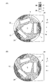
- A is a schematic cross-sectional view of a pulverizer according to an embodiment
- B is a schematic cross-sectional view of a pulverizer as a comparative example. It is a schematic top view of the grinding
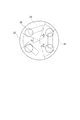
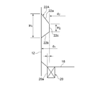
- It is a front view sectional view of the baffle part concerning one embodiment. It is a housing development view of a crushing device concerning one embodiment.
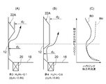
- (A) And (B) is front sectional drawing of the baffle part which concerns on each embodiment,
- C) is a graph which shows distribution in the housing height direction of the housing axial speed of an updraft.
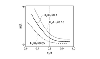
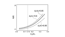
- d 2 / d 1 is a graph showing the effect on flow contraction effect.
- (A) And (B) is front sectional drawing of the baffle part which concerns on each embodiment
- (C) is a graph which shows distribution in the housing height direction of the housing axial speed of an updraft.
- H 2 / H 1 is a graph showing the effect on flow contraction effect.
- (A) And (B) is a planar view sectional drawing of the baffle part which concerns on embodiment, respectively
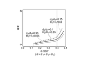
- (C) is a graph which shows distribution in the housing height direction of the housing axial speed of an updraft. It is a graph which shows the influence which (theta) has on the contraction effect.
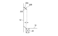
- It is a front view sectional view of the baffle part concerning one embodiment. It is a systematic diagram of the pulverized coal burning boiler concerning one embodiment.
- an expression indicating that things such as “identical”, “equal”, and “homogeneous” are in an equal state not only represents an exactly equal state, but also has a tolerance or a difference that can provide the same function. It also represents the existing state.
- expressions representing shapes such as quadrangular shapes and cylindrical shapes represent not only geometrically strict shapes such as quadrangular shapes and cylindrical shapes, but also irregularities and chamfers as long as the same effects can be obtained. A shape including a part or the like is also expressed.
- the expressions “comprising”, “comprising”, “comprising”, “including”, or “having” one constituent element are not exclusive expressions for excluding the existence of other constituent elements.
- FIG. 1 is a schematic front sectional view of a crushing apparatus according to an embodiment.
- FIG. 2A is a schematic plan sectional view of the crushing apparatus according to one embodiment.
- FIG. 3 is a schematic plan view sectional view of a conventional pulverizer.
- the pulverization apparatus 10 includes a housing 12, and a pulverization unit 14 and a classification unit 16 provided inside the housing 12.
- the crushing unit 14 includes a crushing table 18 configured to rotate, and a throat 20 that is provided on the outer periphery of the crushing table 18 and that forms an updraft fu inside the housing 12.
- the material to be crushed supplied on the pulverizing table 18 is pulverized, and the pulverized particles that have been pulverized into particles rise as a result of the ascending air flow fu ejected from the throat 20.
- the classifying unit 16 is provided above the crushing table 18 and is configured to classify the pulverized particles accompanying the rising air flow fu into fine particles Pm and coarse particles Pc.
- the fine particles Pm pass through the classification unit 16 together with the carrier gas and are sent to the use destination.
- the coarse particles Pc classified as the fine particles Pm return to the crushing table 18.
- a baffle portion 22 is provided on the inner wall surface of the housing 12 between the grinding table 18 and the classification portion 16 in the height direction of the housing 12. The baffle portion 22 protrudes toward the central axis O of the housing 12 and extends only to a partial region in the circumferential direction of the housing 12.
- a pulverized material supply pipe 24 into which the pulverized material Mr is charged and a fine particle discharging unit 26 for discharging the pulverized and classified fine particles Pm to the outside are provided.
- the fine particle discharge unit 26 is constituted by, for example, a tubular discharge pipe.
- the supply pipe 24 is provided in the upper part of the housing 12, and is configured such that the material to be pulverized Mr charged into the supply pipe 24 is supplied onto the pulverization table 18.
- the discharge part 26 is provided at the upper part of the classification part 16 so as to communicate with the classification part 16, and is provided so that the fine particles Pm classified by the classification part 16 can be discharged to the outside.
- the pulverization unit 14 includes a pulverization table 18 and a pulverization roller 28 for pulverizing the object to be pulverized Mr.
- the pulverization object Mr. And crushed by biting.
- the crushing table 18 is rotated by the drive unit 30.
- the object to be pulverized Mr introduced from the supply pipe 24 falls onto the rotating pulverizing table 18 and then moves on the pulverizing table 18 to the outer peripheral side by the centrifugal force generated by the rotation of the pulverizing table 18. It is pulverized by biting with the pulverizing roller 28.
- the crushing roller 28 is configured to be pressed against the crushing table 18 by a pressure device 32.
- the carrier gas g supplied from the carrier gas duct 34 is ejected from the throat 20 into the housing 12.
- the carrier gas g is swirled into the housing 12 by a plurality of throat vanes (not shown) provided in the throat 20.
- the pulverized particles obtained by pulverizing the object to be pulverized Mr ascend with the ascending air flow fu formed by the carrier gas g and ascend the outer peripheral side region in the housing 12. During the ascending, a part of the coarse particles Pc contained in the pulverized particles falls by gravity classification and returns to the pulverization table 18.
- the flow of the ascending air fu squirting from the throat 20 is blocked by the baffle part 22, and ascends above the baffle part 22 (on the downstream side of the ascending air fu when viewed from the baffle part 22) as shown in FIG.
- a region c where the flow velocity of the air flow fu is low is formed.
- 2 (A) and 2 (B) the inside of the housing 12 at the position in the height direction between the baffle portion 22 and the classification portion 16 is divided into regions a, b, and c for each region where the flow velocity of the ascending air fu is different. These are shown separately.
- the flow velocity of the updraft fu in the regions a, b, and c has a relationship of c ⁇ b ⁇ a.
- the coarse particles Pc classified as the fine particles Pm in the classification unit 16 can smoothly return to the pulverization table 18 through the region c where the flow velocity of the ascending air flow fu is low, and thereby the coarse particles Pc in the vicinity of the classification unit 16. Therefore, a decrease in the fineness of the fine particles Pm on the outlet side of the classification unit 16 can be suppressed. Further, since the classified coarse particles Pc can be smoothly returned to the pulverization table 18, re-pulverization of the coarse particles Pc is promoted, and the amount of coarse particles circulating in the housing can be reduced, so that the pressure loss in the housing can be reduced. The increase in power of the crushing device 10 can be suppressed.
- the baffle portion 22 since the baffle portion 22 is provided only in a part of the circumferential direction of the housing 12, the baffle portion 22 does not inhibit the upward air flow fu in the region where the baffle portion 22 is not provided. Can be suppressed.
- the region c is not formed above the baffle portion 22 because there is no baffle portion 22.
- the baffle portion is provided in the whole area in the circumferential direction of the housing, a contracted flow path is formed in the housing, the rising air flow fu is uniformly increased in the housing circumferential direction, and the rising air flow fu is partially increased in the housing circumferential direction. There may be a case where the region c having a low flow velocity is not formed.
- the plurality of baffle portions 22 are arranged at intervals in the circumferential direction of the housing 12. Thereby, in the circumferential direction of the housing 12, a plurality of regions c where the flow velocity of the ascending air flow fu is slow can be formed, so that the classified coarse particles Pc can be smoothly returned to the pulverization unit 14.
- a plurality of crushing rollers 28 are provided at intervals in the circumferential direction of the housing 12.
- Each crushing roller 28 presses and crushes the object to be crushed Mr supplied on the crushing table 18.
- the baffle portion 22 is disposed so as to occupy at least a part of a region in the circumferential direction of the housing between two adjacent crushing rollers 28 among the plurality of crushing rollers 28.
- the space in which the upward air flow fu is formed becomes narrow due to the presence of the pulverizing roller 28. Conceivable. Therefore, as in this embodiment, by providing the baffle portion 22 in the circumferential region between the crushing rollers 28, the region c where the upward air flow fu is slow can be formed relatively easily above the baffle portion 22.
- a plurality of particulate discharge portions 26 are spaced apart from one another in the housing circumferential direction at the top of the housing 12, and the baffle portion 22 is at least partially in the housing circumferential direction. Thus, it extends in the circumferential direction of the housing so as to overlap the discharge portion 26.
- the baffle portion 22 by causing the baffle portion 22 to overlap the discharge portion 26 in the circumferential direction of the housing, a short-circuited channel is formed between the coarse particles Pc staying on the inlet side of the classification portion 16 and the discharge portion 26. Can be avoided. Thereby, the probability that the coarse particles Pc pass through the classification unit 16 and reach the discharge unit 26 can be reduced, and the fineness of the fine particles Pm on the pulverizer outlet side can be improved.
- the upper surface 22 a of the baffle portion 22 ⁇ / b> A is provided above the crushing roller 28, and is an inclined surface that descends toward the central axis O (see FIG. 1) of the housing 12. including.
- the coarse particles Pc dropped on the upper surface 22a fall on the crushing table 18 without staying on the upper surface 22a.
- the coarse particles Pc that cannot pass through the classification unit 16 quickly return to the crushing table 18, so that the pressure loss in the housing 12 can be suppressed.
- the classifying unit 16 includes an annular rotating unit 38 that is rotatable about a rotating shaft (a central axis O of the housing 12).
- the annular rotating portion 38 includes a plurality of rotating fins 40 that are arranged around the central axis O of the housing 12 with a gap therebetween and are rotatable about the central axis O.
- the plurality of rotating fins 40 are arranged directly facing a region in the internal space of the housing 12 where the updraft fu exists. That is, no hopper is provided at a height position between the annular rotating portion 38 and the pulverizing portion 14, and there is no member that blocks the airflow between the rotating fins 40 of the annular rotating portion 38 and the pulverizing portion 14.
- centrifugal classification using a plurality of rotating fins 40 and collision classification by collision of coarse particles Pc with the rotating fins 40 are performed, and the particles are classified into fine particles Pm and coarse particles Pc.
- the supply pipe 24 is provided in the vertical direction on the upper portion of the housing 12 so that its axis coincides with the central axis O.
- An annular portion 12 a formed integrally with the housing 12 is disposed around the supply pipe 24, and the supply pipe 24 is rotatably supported by the annular portion 12 a via a bearing 36.
- the plurality of rotating fins 40 are attached to the supply pipe 24 and rotate together with the supply pipe 24.
- a rectifying cone 42 is attached to the lower portion of the supply pipe 24 so as to be positioned below the rotary fin 40.
- a motor 44 is provided on the upper surface of the housing 12, and the output of the motor 44 is transmitted to the supply pipe 24 via the speed reducer 46, the belt 48 and the pulley 50.
- the motor 44 rotates the supply pipe 24, the annular rotating portion 38, and the rectifying cone 42 around the central axis O.
- the coarse particles Pc classified as the fine particles Pm by the classification unit 16 can smoothly return to the pulverization table 18 from the region c where the flow velocity of the ascending air flow fu is slow. No need to install a hopper to return to Therefore, the housing 12 can be made compact.
- the throat 20 is configured to provide a swirl along the circumferential direction of the housing with respect to the ascending air fu, for example, as indicated by the arrows in FIGS.
- the carrier gas g is given a swirling flow along the circumferential direction of the housing by a plurality of throat vanes (not shown) provided in the throat 20.
- the lower surface 22b of the baffle portion 22A is inclined downward from the upstream side to the downstream side of the swirl flow in the circumferential direction of the housing.
- a distance to the housing wall from the central axis O of the housing 12 as d 1 0.8 ⁇ d 2 / d 1 ⁇ 0.95
- (C) shows the distribution in the housing height direction of the flow velocity in the housing axial direction of the rising air flow fu when the baffle portion 22A shown in the configuration examples 1 and 2 is adopted. From FIG.
- FIG. 7 shows the relationship between d 2 / d 1 and the contraction effect and baffle effect. From FIG. 7, by setting 0.8 ⁇ d 2 / d 1 , it is possible to enhance the baffle effect by the baffle portion 22A while suppressing an increase in the flow velocity of the updraft due to the contraction effect, and d 2 / d 1 ⁇ 0. It can be seen that the baffle effect can be effectively expressed by setting the ratio to .95. Moreover, if the upward flow velocity fu reaches the classification unit 16 with a high upward flow velocity, the classification performance of the classification unit 16 may be deteriorated.
- (C) shows the distribution in the housing height direction of the flow velocity in the housing axial direction of the updraft fu when the baffle portion 22A shown in the configuration examples 3 and 4 is employed. From FIG. 8C, it can be seen that the configuration example 3 can reduce the housing axial flow velocity of the upward air flow fu above the baffle portion 22 ⁇ / b> A than the configuration example 4. This is considered to be because, when H 2 / H 1 exceeds 0.15, the contraction effect increases, and the housing axial flow rate of the ascending air fu increases.
- FIG. 9 shows the relationship between H 2 / H 1 and the contraction effect and baffle effect. From FIG. 9, it can be seen that by setting H 2 / H 1 ⁇ 0.15, the baffle effect by the baffle portion 22A can be enhanced while suppressing an increase in the flow velocity of the rising airflow due to the contraction effect.
- (C) shows the distribution in the housing height direction of the flow velocity in the housing axial direction of the updraft fu when the baffle portion 22A shown in the configuration examples 5 and 6 is adopted. From FIG. 10C, it can be seen that the configuration example 5 can reduce the housing axial flow velocity of the upward air flow fu above the baffle portion 22A than the configuration example 6.
- FIG. 11 shows the relationship between ⁇ / 360 ° and the contraction effect and baffle effect. From FIG. 11, it can be seen that the baffle effect can be effectively expressed by setting 0.2 ⁇ ⁇ / 360 °. Further, by setting ⁇ / 360 ° ⁇ 0.4, it is possible to enhance the baffle effect by the baffle portion 22A while suppressing an increase in the flow velocity of the rising air flow fu due to the contraction effect.
- the protruding end of the baffle portion 22 ⁇ / b> A is located on the inner side in the housing radial direction than the outer peripheral edge 20 a of the throat 20.
- the baffle portion 22A can inhibit the updraft fu and the flow velocity of the updraft fu is low above the baffle portion 22A. c can be formed.
- the baffle portion 22 ⁇ / b> B is configured to have a plate-like cross section, and the baffle portion 22 ⁇ / b> B is located at a height position between the crushing table 18 and the classification portion 16. It protrudes toward the center axis O of the housing 12 and extends only to a partial region in the circumferential direction of the housing 12.
- the flow of the updraft fu can be inhibited (baffle effect), and a region where the flow rate of the updraft fu is low can be formed above the baffle portion 22B.
- the coarse particles Pc classified into the fine particles Pm by the classification unit 16 can move down the region c and smoothly return to the pulverization table 18.
- the retention of the coarse particles Pc in the vicinity of the classification unit 16 can be suppressed, and a decrease in the fineness of the fine particles Pm on the outlet side of the classification unit 16 can be suppressed.
- the classified coarse particles Pc can be smoothly returned to the pulverization table 18, re-pulverization of the coarse particles Pc is promoted, and the amount of coarse particles circulating in the housing can be reduced, so that the pressure loss in the housing can be reduced.
- the increase in power of the crushing device 10 can be suppressed.
- the baffle portion 22 is provided only in a part of the circumferential direction of the housing 12, the baffle portion 22 does not inhibit the upward air flow fu in the region where the baffle portion 22 is not provided. Can be suppressed.
- the upper surface 22 a of the baffle portion 22 ⁇ / b> B has an inclined surface that is provided above the crushing roller 28 and descends toward the central axis O of the housing 12.
- the coarse particles Pc that have fallen on the upper surface 22a of the baffle portion 22B fall on the grinding roller 28 without staying on the upper surface 22a.
- the coarse particles Pc that cannot pass through the classification unit 16 quickly return to the crushing table 18, so that the pressure loss in the housing 12 can be suppressed.
- the lower surface 22b of the baffle portion 22B is seen from the upstream side of the swirling flow of the updraft fu in the circumferential direction of the housing. You may comprise so that it may incline below toward the downstream side. Accordingly, the coarse particles Pc accompanying the ascending air fu are caused to collide with the lower surface 22b, so that the relatively large diameter coarse particles can be separated from the ascending air fu.
- the object to be pulverized Mr is coal
- the coal is supplied from the supply pipe 24, supplied onto the pulverization table 18, and pulverized into coal particles.
- the classification unit 16 the coal particles are classified into fine particles Pm and coarse particles Pc, and the fine particles Pm are taken out of the pulverizing apparatus 10.
- the retention of the coarse particles Pc in the vicinity of the classifying unit 16 can be suppressed, so that a decrease in the fineness of the fine particles Pm on the pulverizer outlet side can be suppressed.
- the pressure loss in the housing 12 can be reduced and the increase in power of the pulverizer 10 can be suppressed.
- the baffle portion 22 only in a part in the circumferential direction of the housing, the retention of the coarse particles Pc can be suppressed without inhibiting the ascending air flow fu, so that the pressure loss in the housing can be suppressed.
- the pulverized coal burning boiler 60 includes a pulverization apparatus 10 and a furnace 62 for burning the pulverized coal Cm obtained by the pulverization apparatus 10.
- air A is sent from the blower 64 to the pulverizer 10, and coal as a raw material (a material to be crushed) is supplied from the coal bunker 70 and the coal feeder 72.
- Combustion air A fed into the blower 64 is branched into the air A 1 and the air A 2.
- the air A 1 is conveyed to the grinding device 10 by the blower 66.
- Part of the air A 1 is conveyed to the grinding device 10 as being heated warm air by preheater 80.
- the warm air heated by the preheater 80 and the cold air directly conveyed from the blower 66 without passing through the preheater 80 are mixed and adjusted so that the mixed air has an appropriate temperature, and then the pulverizing apparatus 10. May be supplied.
- the air A 1 supplied to the pulverizing apparatus 10 is blown out from the throat 20 (see FIG. 1) into the housing 12 inside the pulverizing apparatus 10.
- Coal as the material to be pulverized Mr is fed into the coal bunker 70 and then supplied to the pulverizing apparatus 10 by the coal feeder 72 through the supply pipe 24 (see FIG. 1).
- the pulverized coal Cm generated by being pulverized by the pulverizing apparatus 10 while being dried by the air flow of the air A 1 from the throat 20 is conveyed by the air A 1 from the discharge unit 26 (see FIG. 1), and is a wind box of the furnace 62. It is sent to a furnace (boiler body) 62 through a pulverized coal burner (not shown) in 74 and ignited by the burner to burn.
- the air A 2 is heated by the preheater 68 and the preheater 80, sent to the furnace 62 through the wind box 74, and pulverized coal Cm in the furnace 62. Used for combustion.
- the exhaust gas generated by the combustion of pulverized coal Cm in the furnace 62 is sent to the denitration device 78 after the dust is removed by the dust collector 76, and nitrogen oxide (NOx) contained in the exhaust gas is reduced.
- the exhaust gas is sucked by the blower 82 through the preheater 80, the sulfur content is removed by the desulfurization device 84, and released from the chimney 86 into the atmosphere.
- the coarse particles Pc classified as the pulverized coal Cm by the classification unit 16 can be smoothly returned to the pulverization table 18 in the pulverization apparatus 10.
- the fineness of the fine particles Pm on the pulverizer outlet side can be improved, the pressure loss in the housing 12 can be reduced, and the increase in power of the pulverizer 10 can be suppressed.
- the pulverized coal Cm in which the mixing of the coarse particles Pc is suppressed is combusted, it is possible to reduce air pollutants such as NOx in the combustion gas, and to reduce the unburned matter in the ash, thereby improving the boiler efficiency. Can be improved.
- the present invention it is possible to suppress a decrease in the fine particle size of the outlet side fine particles of the pulverizer, and to suppress an increase in pressure loss in the housing of the pulverizer, thereby suppressing an increase in power of the pulverizer.
- air pollutants such as NOx in the combustion gas can be reduced, and unburned ash content can be reduced.
Landscapes
- Engineering & Computer Science (AREA)
- Chemical & Material Sciences (AREA)
- Combustion & Propulsion (AREA)
- Mechanical Engineering (AREA)
- General Engineering & Computer Science (AREA)
- Food Science & Technology (AREA)
- Crushing And Grinding (AREA)
Abstract
L'invention concerne un dispositif de broyage comprenant : un logement ; une table de broyage conçue de façon à tourner à l'intérieur du logement ; une gorge pour former un flux d'air ascendant à l'intérieur du logement, ladite gorge étant disposée sur le côté circonférentiel extérieur de la table de broyage dans le logement ; une section de tri est présente au-dessus de la table de broyage à l'intérieur du logement et est conçue de manière à trier les particules accompagnant le flux d'air ascendant en particules fines et en particules grossières ; et une section à chicane qui fait saillie depuis la surface de paroi intérieure du logement vers le côté axe central du logement en une position située entre la table de broyage et la section de tri dans le sens de la hauteur, ladite section à chicane s'étendant uniquement dans une zone qui fait partie du logement dans le sens circonférentiel de ce dernier.
Applications Claiming Priority (2)
| Application Number | Priority Date | Filing Date | Title |
|---|---|---|---|
| JP2016022847A JP2017140566A (ja) | 2016-02-09 | 2016-02-09 | 粉砕装置及び微粉炭焚きボイラ |
| JP2016-022847 | 2016-02-09 |
Publications (1)
| Publication Number | Publication Date |
|---|---|
| WO2017138294A1 true WO2017138294A1 (fr) | 2017-08-17 |
Family
ID=59563743
Family Applications (1)
| Application Number | Title | Priority Date | Filing Date |
|---|---|---|---|
| PCT/JP2017/000953 Ceased WO2017138294A1 (fr) | 2016-02-09 | 2017-01-13 | Dispositif de broyage et chaudière à charbon pulvérisé |
Country Status (2)
| Country | Link |
|---|---|
| JP (1) | JP2017140566A (fr) |
| WO (1) | WO2017138294A1 (fr) |
Families Citing this family (2)
| Publication number | Priority date | Publication date | Assignee | Title |
|---|---|---|---|---|
| JP7185463B2 (ja) * | 2018-09-27 | 2022-12-07 | 日清エンジニアリング株式会社 | 旋回渦流式分級装置 |
| JP7362253B2 (ja) * | 2019-01-25 | 2023-10-17 | 三菱重工業株式会社 | 固体燃料粉砕装置及びこれを備えた発電プラント並びに固体燃料粉砕装置の制御方法 |
Citations (6)
| Publication number | Priority date | Publication date | Assignee | Title |
|---|---|---|---|---|
| JPS6388055A (ja) * | 1986-09-30 | 1988-04-19 | 宇部興産株式会社 | 竪型粉砕機 |
| JPS6467266A (en) * | 1987-09-08 | 1989-03-13 | Babcock Hitachi Kk | Vertical grinder of rotary classification type |
| JP2009213998A (ja) * | 2008-03-10 | 2009-09-24 | Ihi Corp | 縦型ローラミル |
| JP2009297597A (ja) * | 2008-06-10 | 2009-12-24 | Ihi Corp | 竪型ローラミル |
| JP2013180239A (ja) * | 2012-03-01 | 2013-09-12 | Ihi Corp | バイオマスミル |
| JP2016087544A (ja) * | 2014-11-04 | 2016-05-23 | 株式会社Ihi | 竪型ローラミル |
-
2016
- 2016-02-09 JP JP2016022847A patent/JP2017140566A/ja active Pending
-
2017
- 2017-01-13 WO PCT/JP2017/000953 patent/WO2017138294A1/fr not_active Ceased
Patent Citations (6)
| Publication number | Priority date | Publication date | Assignee | Title |
|---|---|---|---|---|
| JPS6388055A (ja) * | 1986-09-30 | 1988-04-19 | 宇部興産株式会社 | 竪型粉砕機 |
| JPS6467266A (en) * | 1987-09-08 | 1989-03-13 | Babcock Hitachi Kk | Vertical grinder of rotary classification type |
| JP2009213998A (ja) * | 2008-03-10 | 2009-09-24 | Ihi Corp | 縦型ローラミル |
| JP2009297597A (ja) * | 2008-06-10 | 2009-12-24 | Ihi Corp | 竪型ローラミル |
| JP2013180239A (ja) * | 2012-03-01 | 2013-09-12 | Ihi Corp | バイオマスミル |
| JP2016087544A (ja) * | 2014-11-04 | 2016-05-23 | 株式会社Ihi | 竪型ローラミル |
Also Published As
| Publication number | Publication date |
|---|---|
| JP2017140566A (ja) | 2017-08-17 |
Similar Documents
| Publication | Publication Date | Title |
|---|---|---|
| KR101131539B1 (ko) | 분급기, 상기 분급기를 구비한 수직형분쇄기, 및 상기수직형분쇄기를 구비한 석탄분보일러장치 | |
| JP5812668B2 (ja) | 回転式分級機 | |
| JP4865865B2 (ja) | 分級装置及びそれを備えた竪型粉砕装置ならびに石炭焚ボイラ装置 | |
| KR102084866B1 (ko) | 분급기, 분쇄 분급 장치 및 미분탄 연소 보일러 | |
| JP2017140573A (ja) | 分級機、粉砕分級装置及び微粉炭焚きボイラ | |
| KR102111226B1 (ko) | 분쇄 장치, 분쇄 장치의 스로트 및 미분탄 연소 보일러 | |
| JP2017140566A (ja) | 粉砕装置及び微粉炭焚きボイラ | |
| JP2009297597A (ja) | 竪型ローラミル | |
| JP2011240233A (ja) | 竪型粉砕装置ならびに石炭焚ボイラ装置 | |
| JP4272456B2 (ja) | 分級機及びそれを備えた竪型粉砕機、石炭焚ボイラ装置 | |
| TWI671132B (zh) | 分級機、直立式粉碎機以及燃煤鍋爐 |
Legal Events
| Date | Code | Title | Description |
|---|---|---|---|
| 121 | Ep: the epo has been informed by wipo that ep was designated in this application |
Ref document number: 17750019 Country of ref document: EP Kind code of ref document: A1 |
|
| NENP | Non-entry into the national phase |
Ref country code: DE |
|
| 122 | Ep: pct application non-entry in european phase |
Ref document number: 17750019 Country of ref document: EP Kind code of ref document: A1 |