WO2017138459A1 - Dispositif de génération d'image d'onde acoustique et procédé de génération d'image d'onde acoustique - Google Patents
Dispositif de génération d'image d'onde acoustique et procédé de génération d'image d'onde acoustique Download PDFInfo
- Publication number
- WO2017138459A1 WO2017138459A1 PCT/JP2017/004072 JP2017004072W WO2017138459A1 WO 2017138459 A1 WO2017138459 A1 WO 2017138459A1 JP 2017004072 W JP2017004072 W JP 2017004072W WO 2017138459 A1 WO2017138459 A1 WO 2017138459A1
- Authority
- WO
- WIPO (PCT)
- Prior art keywords
- acoustic wave
- photoacoustic
- interest
- image
- reception
- Prior art date
- Legal status (The legal status is an assumption and is not a legal conclusion. Google has not performed a legal analysis and makes no representation as to the accuracy of the status listed.)
- Ceased
Links
Images




Classifications
-
- A—HUMAN NECESSITIES
- A61—MEDICAL OR VETERINARY SCIENCE; HYGIENE
- A61B—DIAGNOSIS; SURGERY; IDENTIFICATION
- A61B8/00—Diagnosis using ultrasonic, sonic or infrasonic waves
- A61B8/48—Diagnostic techniques
- A61B8/488—Diagnostic techniques involving Doppler signals
-
- G—PHYSICS
- G01—MEASURING; TESTING
- G01S—RADIO DIRECTION-FINDING; RADIO NAVIGATION; DETERMINING DISTANCE OR VELOCITY BY USE OF RADIO WAVES; LOCATING OR PRESENCE-DETECTING BY USE OF THE REFLECTION OR RERADIATION OF RADIO WAVES; ANALOGOUS ARRANGEMENTS USING OTHER WAVES
- G01S7/00—Details of systems according to groups G01S13/00, G01S15/00, G01S17/00
- G01S7/52—Details of systems according to groups G01S13/00, G01S15/00, G01S17/00 of systems according to group G01S15/00
- G01S7/52017—Details of systems according to groups G01S13/00, G01S15/00, G01S17/00 of systems according to group G01S15/00 particularly adapted to short-range imaging
-
- A—HUMAN NECESSITIES
- A61—MEDICAL OR VETERINARY SCIENCE; HYGIENE
- A61B—DIAGNOSIS; SURGERY; IDENTIFICATION
- A61B5/00—Measuring for diagnostic purposes; Identification of persons
- A61B5/74—Details of notification to user or communication with user or patient; User input means
- A61B5/7475—User input or interface means, e.g. keyboard, pointing device, joystick
- A61B5/748—Selection of a region of interest, e.g. using a graphics tablet
-
- A—HUMAN NECESSITIES
- A61—MEDICAL OR VETERINARY SCIENCE; HYGIENE
- A61B—DIAGNOSIS; SURGERY; IDENTIFICATION
- A61B8/00—Diagnosis using ultrasonic, sonic or infrasonic waves
- A61B8/13—Tomography
-
- A—HUMAN NECESSITIES
- A61—MEDICAL OR VETERINARY SCIENCE; HYGIENE
- A61B—DIAGNOSIS; SURGERY; IDENTIFICATION
- A61B8/00—Diagnosis using ultrasonic, sonic or infrasonic waves
- A61B8/44—Constructional features of the ultrasonic, sonic or infrasonic diagnostic device
- A61B8/4483—Constructional features of the ultrasonic, sonic or infrasonic diagnostic device characterised by features of the ultrasound transducer
-
- A—HUMAN NECESSITIES
- A61—MEDICAL OR VETERINARY SCIENCE; HYGIENE
- A61B—DIAGNOSIS; SURGERY; IDENTIFICATION
- A61B8/00—Diagnosis using ultrasonic, sonic or infrasonic waves
- A61B8/52—Devices using data or image processing specially adapted for diagnosis using ultrasonic, sonic or infrasonic waves
- A61B8/5215—Devices using data or image processing specially adapted for diagnosis using ultrasonic, sonic or infrasonic waves involving processing of medical diagnostic data
- A61B8/5238—Devices using data or image processing specially adapted for diagnosis using ultrasonic, sonic or infrasonic waves involving processing of medical diagnostic data for combining image data of patient, e.g. merging several images from different acquisition modes into one image
- A61B8/5246—Devices using data or image processing specially adapted for diagnosis using ultrasonic, sonic or infrasonic waves involving processing of medical diagnostic data for combining image data of patient, e.g. merging several images from different acquisition modes into one image combining images from the same or different imaging techniques, e.g. color Doppler and B-mode
-
- A—HUMAN NECESSITIES
- A61—MEDICAL OR VETERINARY SCIENCE; HYGIENE
- A61B—DIAGNOSIS; SURGERY; IDENTIFICATION
- A61B8/00—Diagnosis using ultrasonic, sonic or infrasonic waves
- A61B8/54—Control of the diagnostic device
-
- B—PERFORMING OPERATIONS; TRANSPORTING
- B06—GENERATING OR TRANSMITTING MECHANICAL VIBRATIONS IN GENERAL
- B06B—METHODS OR APPARATUS FOR GENERATING OR TRANSMITTING MECHANICAL VIBRATIONS OF INFRASONIC, SONIC, OR ULTRASONIC FREQUENCY, e.g. FOR PERFORMING MECHANICAL WORK IN GENERAL
- B06B1/00—Methods or apparatus for generating mechanical vibrations of infrasonic, sonic, or ultrasonic frequency
- B06B1/02—Methods or apparatus for generating mechanical vibrations of infrasonic, sonic, or ultrasonic frequency making use of electrical energy
- B06B1/0207—Driving circuits
-
- G—PHYSICS
- G01—MEASURING; TESTING
- G01N—INVESTIGATING OR ANALYSING MATERIALS BY DETERMINING THEIR CHEMICAL OR PHYSICAL PROPERTIES
- G01N29/00—Investigating or analysing materials by the use of ultrasonic, sonic or infrasonic waves; Visualisation of the interior of objects by transmitting ultrasonic or sonic waves through the object
- G01N29/04—Analysing solids
- G01N29/06—Visualisation of the interior, e.g. acoustic microscopy
- G01N29/0654—Imaging
- G01N29/0672—Imaging by acoustic tomography
-
- G—PHYSICS
- G01—MEASURING; TESTING
- G01N—INVESTIGATING OR ANALYSING MATERIALS BY DETERMINING THEIR CHEMICAL OR PHYSICAL PROPERTIES
- G01N29/00—Investigating or analysing materials by the use of ultrasonic, sonic or infrasonic waves; Visualisation of the interior of objects by transmitting ultrasonic or sonic waves through the object
- G01N29/22—Details, e.g. general constructional or apparatus details
- G01N29/24—Probes
- G01N29/2418—Probes using optoacoustic interaction with the material, e.g. laser radiation, photoacoustics
-
- G—PHYSICS
- G01—MEASURING; TESTING
- G01S—RADIO DIRECTION-FINDING; RADIO NAVIGATION; DETERMINING DISTANCE OR VELOCITY BY USE OF RADIO WAVES; LOCATING OR PRESENCE-DETECTING BY USE OF THE REFLECTION OR RERADIATION OF RADIO WAVES; ANALOGOUS ARRANGEMENTS USING OTHER WAVES
- G01S15/00—Systems using the reflection or reradiation of acoustic waves, e.g. sonar systems
- G01S15/88—Sonar systems specially adapted for specific applications
- G01S15/89—Sonar systems specially adapted for specific applications for mapping or imaging
- G01S15/8906—Short-range imaging systems; Acoustic microscope systems using pulse-echo techniques
- G01S15/8909—Short-range imaging systems; Acoustic microscope systems using pulse-echo techniques using a static transducer configuration
- G01S15/8915—Short-range imaging systems; Acoustic microscope systems using pulse-echo techniques using a static transducer configuration using a transducer array
-
- G—PHYSICS
- G01—MEASURING; TESTING
- G01S—RADIO DIRECTION-FINDING; RADIO NAVIGATION; DETERMINING DISTANCE OR VELOCITY BY USE OF RADIO WAVES; LOCATING OR PRESENCE-DETECTING BY USE OF THE REFLECTION OR RERADIATION OF RADIO WAVES; ANALOGOUS ARRANGEMENTS USING OTHER WAVES
- G01S15/00—Systems using the reflection or reradiation of acoustic waves, e.g. sonar systems
- G01S15/88—Sonar systems specially adapted for specific applications
- G01S15/89—Sonar systems specially adapted for specific applications for mapping or imaging
- G01S15/8906—Short-range imaging systems; Acoustic microscope systems using pulse-echo techniques
- G01S15/8979—Combined Doppler and pulse-echo imaging systems
-
- G—PHYSICS
- G01—MEASURING; TESTING
- G01S—RADIO DIRECTION-FINDING; RADIO NAVIGATION; DETERMINING DISTANCE OR VELOCITY BY USE OF RADIO WAVES; LOCATING OR PRESENCE-DETECTING BY USE OF THE REFLECTION OR RERADIATION OF RADIO WAVES; ANALOGOUS ARRANGEMENTS USING OTHER WAVES
- G01S7/00—Details of systems according to groups G01S13/00, G01S15/00, G01S17/00
- G01S7/52—Details of systems according to groups G01S13/00, G01S15/00, G01S17/00 of systems according to group G01S15/00
- G01S7/52017—Details of systems according to groups G01S13/00, G01S15/00, G01S17/00 of systems according to group G01S15/00 particularly adapted to short-range imaging
- G01S7/52023—Details of receivers
- G01S7/52025—Details of receivers for pulse systems
-
- G—PHYSICS
- G01—MEASURING; TESTING
- G01S—RADIO DIRECTION-FINDING; RADIO NAVIGATION; DETERMINING DISTANCE OR VELOCITY BY USE OF RADIO WAVES; LOCATING OR PRESENCE-DETECTING BY USE OF THE REFLECTION OR RERADIATION OF RADIO WAVES; ANALOGOUS ARRANGEMENTS USING OTHER WAVES
- G01S7/00—Details of systems according to groups G01S13/00, G01S15/00, G01S17/00
- G01S7/52—Details of systems according to groups G01S13/00, G01S15/00, G01S17/00 of systems according to group G01S15/00
- G01S7/52017—Details of systems according to groups G01S13/00, G01S15/00, G01S17/00 of systems according to group G01S15/00 particularly adapted to short-range imaging
- G01S7/52053—Display arrangements
- G01S7/52057—Cathode ray tube displays
- G01S7/5206—Two-dimensional coordinated display of distance and direction; B-scan display
- G01S7/52063—Sector scan display
-
- G—PHYSICS
- G01—MEASURING; TESTING
- G01S—RADIO DIRECTION-FINDING; RADIO NAVIGATION; DETERMINING DISTANCE OR VELOCITY BY USE OF RADIO WAVES; LOCATING OR PRESENCE-DETECTING BY USE OF THE REFLECTION OR RERADIATION OF RADIO WAVES; ANALOGOUS ARRANGEMENTS USING OTHER WAVES
- G01S7/00—Details of systems according to groups G01S13/00, G01S15/00, G01S17/00
- G01S7/52—Details of systems according to groups G01S13/00, G01S15/00, G01S17/00 of systems according to group G01S15/00
- G01S7/52017—Details of systems according to groups G01S13/00, G01S15/00, G01S17/00 of systems according to group G01S15/00 particularly adapted to short-range imaging
- G01S7/52098—Details of systems according to groups G01S13/00, G01S15/00, G01S17/00 of systems according to group G01S15/00 particularly adapted to short-range imaging related to workflow protocols
-
- A—HUMAN NECESSITIES
- A61—MEDICAL OR VETERINARY SCIENCE; HYGIENE
- A61B—DIAGNOSIS; SURGERY; IDENTIFICATION
- A61B5/00—Measuring for diagnostic purposes; Identification of persons
- A61B5/0093—Detecting, measuring or recording by applying one single type of energy and measuring its conversion into another type of energy
- A61B5/0095—Detecting, measuring or recording by applying one single type of energy and measuring its conversion into another type of energy by applying light and detecting acoustic waves, i.e. photoacoustic measurements
-
- A—HUMAN NECESSITIES
- A61—MEDICAL OR VETERINARY SCIENCE; HYGIENE
- A61B—DIAGNOSIS; SURGERY; IDENTIFICATION
- A61B5/00—Measuring for diagnostic purposes; Identification of persons
- A61B5/02—Detecting, measuring or recording for evaluating the cardiovascular system, e.g. pulse, heart rate, blood pressure or blood flow
- A61B5/02007—Evaluating blood vessel condition, e.g. elasticity, compliance
-
- B—PERFORMING OPERATIONS; TRANSPORTING
- B06—GENERATING OR TRANSMITTING MECHANICAL VIBRATIONS IN GENERAL
- B06B—METHODS OR APPARATUS FOR GENERATING OR TRANSMITTING MECHANICAL VIBRATIONS OF INFRASONIC, SONIC, OR ULTRASONIC FREQUENCY, e.g. FOR PERFORMING MECHANICAL WORK IN GENERAL
- B06B1/00—Methods or apparatus for generating mechanical vibrations of infrasonic, sonic, or ultrasonic frequency
- B06B1/02—Methods or apparatus for generating mechanical vibrations of infrasonic, sonic, or ultrasonic frequency making use of electrical energy
- B06B1/06—Methods or apparatus for generating mechanical vibrations of infrasonic, sonic, or ultrasonic frequency making use of electrical energy operating with piezoelectric effect or with electrostriction
- B06B1/0607—Methods or apparatus for generating mechanical vibrations of infrasonic, sonic, or ultrasonic frequency making use of electrical energy operating with piezoelectric effect or with electrostriction using multiple elements
- B06B1/0622—Methods or apparatus for generating mechanical vibrations of infrasonic, sonic, or ultrasonic frequency making use of electrical energy operating with piezoelectric effect or with electrostriction using multiple elements on one surface
-
- B—PERFORMING OPERATIONS; TRANSPORTING
- B06—GENERATING OR TRANSMITTING MECHANICAL VIBRATIONS IN GENERAL
- B06B—METHODS OR APPARATUS FOR GENERATING OR TRANSMITTING MECHANICAL VIBRATIONS OF INFRASONIC, SONIC, OR ULTRASONIC FREQUENCY, e.g. FOR PERFORMING MECHANICAL WORK IN GENERAL
- B06B2201/00—Indexing scheme associated with B06B1/0207 for details covered by B06B1/0207 but not provided for in any of its subgroups
- B06B2201/50—Application to a particular transducer type
- B06B2201/55—Piezoelectric transducer
- B06B2201/56—Foil type, e.g. PVDF
-
- B—PERFORMING OPERATIONS; TRANSPORTING
- B06—GENERATING OR TRANSMITTING MECHANICAL VIBRATIONS IN GENERAL
- B06B—METHODS OR APPARATUS FOR GENERATING OR TRANSMITTING MECHANICAL VIBRATIONS OF INFRASONIC, SONIC, OR ULTRASONIC FREQUENCY, e.g. FOR PERFORMING MECHANICAL WORK IN GENERAL
- B06B2201/00—Indexing scheme associated with B06B1/0207 for details covered by B06B1/0207 but not provided for in any of its subgroups
- B06B2201/70—Specific application
- B06B2201/76—Medical, dental
Definitions
- the present invention relates to an apparatus for generating an acoustic wave image and a method for generating an acoustic wave image.
- This measurement method emits pulsed light having a certain appropriate wavelength (for example, visible light, near-infrared light, or mid-infrared light wavelength band) toward the subject, and the absorbing substance in the subject is subjected to this pulse.
- a photoacoustic wave which is an elastic wave generated as a result of absorbing light energy, is detected, and the concentration of the absorbing substance is quantitatively measured.
- the absorbing substance in the subject is, for example, glucose or hemoglobin contained in blood.
- a technique for detecting such a photoacoustic wave and generating a photoacoustic image based on the detection signal is called photoacoustic imaging (PAI) or photoacoustic tomography (PAT). Yes.
- Patent Documents 1 and 2 show apparatuses that perform photoacoustic imaging to generate a photoacoustic image.
- This type of photoacoustic image generation apparatus is often configured to generate a so-called reflected ultrasonic image as disclosed in Patent Document 2.
- an apparatus for generating a reflected ultrasound image is based on a signal obtained by detecting a reflected acoustic wave reflected in the subject by an acoustic wave (mostly an ultrasonic wave) emitted toward the subject.
- a tomographic image or the like inside the specimen is generated.
- velocity information is analyzed from the reflected ultrasonic detection signal, and blood flow, tissue, and contrast agent echo components due to the Doppler effect are extracted, for example, Doppler indicating a blood flow portion.
- Devices for generating images are also known. This Doppler image is often created by an apparatus that generates a photoacoustic image, as shown in Patent Document 3.
- a photoacoustic image generation device generally emits light such as laser light toward a subject and absorbs this light to detect a photoacoustic wave generated from within the subject and based on a signal obtained. Thus, a photoacoustic image showing the internal tissue of the subject is generated.
- an image generated based on the reflected ultrasonic detection signal and an image generated based on the photoacoustic wave detection signal are collectively referred to as an acoustic wave image.
- JP2013-1558531A Japanese Patent Laying-Open No. 2015-181660 JP 2014-136103 A
- the Doppler image there is a demand for enabling simultaneous observation of photoacoustic images. For example, in a Doppler image, it is possible to see a blood flow part and the like, and in a photoacoustic image, it is possible to see blood vessels by visualizing hemoglobin and the like in blood.
- the photoacoustic image has lower real-time characteristics than the Doppler image. That is, while the repetition frequency of Doppler image generation can be secured at 30 Hz (frame rate is 30 frames / second), the repetition frequency of photoacoustic image generation may require light emission toward the subject. It is limited to about 10 Hz (frame rate is 10 frames / second).
- the present invention has been made in view of the above problems, and an acoustic wave image that can generate both an image generated based on a reflected ultrasonic detection signal and an image generated based on a photoacoustic wave detection signal.
- An object of the generation apparatus and method is to ensure a high frame rate for photoacoustic image generation.
- the acoustic wave image generation apparatus is: A photoacoustic image is generated based on a signal obtained by detecting a photoacoustic wave generated from within the subject by an acoustic wave detection probe by receiving light emitted toward the subject, and relates to the subject
- an acoustic wave image generation device that generates a Doppler image
- Means for setting a region of interest in a Doppler image Based on the size of the set region of interest, the reception aperture for detecting the photoacoustic wave of the acoustic wave detection probe is set to an aperture smaller than all the reception apertures of the acoustic wave detection probe, and acoustic wave detection is performed.
- Receiving aperture control means for setting the position of the receiving aperture for detecting the photoacoustic wave of the probe based on the position of the set region of interest; It is what has.
- the reception aperture control means is preferably a means for blocking a photoacoustic wave detection signal output from at least some of the acoustic wave transducers other than the acoustic wave transducer serving as the reception aperture.
- the reception aperture control means sets all the acoustic wave transducers arranged facing the entire region of interest to the reception aperture.
- the reception aperture control means sets only a part of the acoustic wave transducers as reception apertures among the acoustic transducers arranged opposite to the entire region of interest. It may be.
- the reception aperture control means may be configured such that the part of the acoustic wave transducers is more at a position facing the center of the region of interest than at a position facing the end of the region of interest. It is desirable to set it in a dense state.
- the acoustic wave image generation device of the present invention is a signal output from acoustic wave transducers other than the some acoustic wave transducers among the plurality of acoustic wave transducers arranged facing the entire region of interest. It is desirable to further include means for interpolating signals output from the some acoustic wave transducers.
- the acoustic wave image generation method of the present invention includes: A photoacoustic image is generated based on a signal obtained by detecting a photoacoustic wave generated from within the subject by an acoustic wave detection probe by receiving light emitted toward the subject, and relates to the subject
- an acoustic wave image generation method for generating a Doppler image Set the region of interest in the Doppler image, Based on the size of the set region of interest, the reception aperture for detecting the photoacoustic wave of the acoustic wave detection probe is set to an aperture smaller than all the reception apertures of the acoustic wave detection probe, and acoustic wave detection is performed. The position of the reception aperture for detecting the photoacoustic wave of the probe is set based on the set position of the region of interest.
- an acoustic wave detection probe in which a plurality of acoustic wave transducers capable of detecting photoacoustic waves are arranged in parallel is used. It is desirable to set the reception aperture by blocking the photoacoustic wave detection signals output from at least some of the acoustic wave transducers other than the acoustic wave transducer serving as the reception aperture.
- the acoustic wave image generation method of the present invention it is desirable to set all the acoustic wave transducers arranged facing the entire region of interest in the reception aperture.
- acoustic wave image generation method of the present invention only some acoustic wave transducers among the acoustic wave transducers arranged side by side across the entire region of interest may be set in the reception aperture.
- the acoustic wave image is output from acoustic wave transducers other than the some acoustic wave transducers among the plurality of acoustic wave transducers arranged opposite to the entire region of interest. It is desirable to obtain the signal by interpolating the signals output from the part of the acoustic wave vibrators.
- the frame rate of photoacoustic image generation can be kept high.
- Schematic which shows the whole structure of the acoustic wave image generation apparatus which concerns on one Embodiment of this invention.
- Schematic showing an example of reception aperture setting of an acoustic wave detection probe Schematic showing examples of region of interest settings
- Schematic showing another example of reception aperture setting of acoustic wave detection probe
- Schematic showing yet another example of reception aperture setting of the acoustic wave detection probe
- Schematic showing yet another example of reception aperture setting of the acoustic wave detection probe
- Schematic showing yet another example of reception aperture setting of the acoustic wave detection probe
- Schematic showing yet another example of reception aperture setting of the acoustic wave detection probe Schematic showing the superimposed display state of Doppler image and photoacoustic image
- FIG. 1 is a schematic diagram showing an overall configuration of an acoustic wave image generation apparatus 10 according to an embodiment of the present invention.
- the shape of an acoustic wave detection probe (hereinafter simply referred to as a probe) 11 is schematically shown.
- the acoustic wave image generation device 10 of this example has a function of generating a photoacoustic image based on a photoacoustic wave detection signal.
- a unit 12, a laser unit 13, an image display unit 14, an input unit 15 and the like are provided.
- those components will be sequentially described.
- the probe 11 has a function of emitting measurement light and ultrasonic waves toward the subject M, which is a living body, for example, and a function of detecting an acoustic wave U propagating in the subject M. That is, the probe 11 can emit (transmit) ultrasonic waves (acoustic waves) to the subject M and detect (receive) reflected ultrasonic waves (reflected acoustic waves) that have been reflected back from the subject M. it can.
- acoustic wave is a term that includes ultrasonic waves and photoacoustic waves.
- the “ultrasonic wave” means an elastic wave transmitted by the probe 11 and its reflected wave (reflected ultrasonic wave)
- the “photoacoustic wave” means an elastic wave that is generated when the absorber 65 absorbs measurement light. Means wave.
- the acoustic wave emitted from the probe 11 is not limited to the ultrasonic wave, and an acoustic wave having an audible frequency may be used as long as an appropriate frequency is selected according to the test object, measurement conditions, and the like.
- Examples of the absorber 65 in the subject M include blood vessels and metal members.
- the probe 11 is generally prepared for sector scanning, linear scanning, convex scanning, or the like, and an appropriate one is selected and used according to the imaging region.
- an optical fiber 60 is connected to the probe 11 as a connecting portion that guides laser light L, which is measurement light emitted from a laser unit 13 described later, to the light emitting portion 40.
- the probe 11 includes a transducer array 20 that is an acoustic wave detector, and a total of two light emitting units 40 that are disposed on both sides of the transducer array 20 with the transducer array 20 in between. And a housing 50 in which the transducer array 20 and the two light emitting portions 40 are accommodated.
- the transducer array 20 also functions as an ultrasonic transmission element.
- the transducer array 20 is connected to a circuit for transmitting ultrasonic waves, a circuit for receiving acoustic waves, and the like via wires not shown.
- the transducer array 20 is formed by arranging a plurality of acoustic wave transducers (ultrasonic transducers) as electroacoustic transducers in a one-dimensional direction.
- the acoustic wave vibrator is a piezoelectric element composed of, for example, piezoelectric ceramics.
- the acoustic wave vibrator may be a piezoelectric element made of a polymer film such as polyvinylidene fluoride (PVDF).
- PVDF polyvinylidene fluoride
- the acoustic wave vibrator has a function of converting the received acoustic wave U into an electrical signal.
- the transducer array 20 may include an acoustic lens.
- the transducer array 20 includes a plurality of acoustic wave transducers arranged in a one-dimensional manner, but a vibration in which a plurality of acoustic wave transducers are arranged in a two-dimensional manner.
- a child array may be used.
- the acoustic wave vibrator has a function of transmitting ultrasonic waves as described above. That is, when an alternating voltage is applied to the acoustic wave vibrator, the acoustic wave vibrator generates an ultrasonic wave having a frequency corresponding to the frequency of the alternating voltage. Note that transmission and reception of ultrasonic waves may be separated from each other. That is, for example, ultrasonic waves may be transmitted from a position different from the probe 11, and reflected ultrasonic waves with respect to the transmitted ultrasonic waves may be received by the probe 11.
- the light emitting unit 40 is a part that emits the laser light L guided by the optical fiber 60 toward the subject M.
- the light emitting portion 40 is configured by the tip portion of the optical fiber 60, that is, the end portion far from the laser unit 13 that is a light source of measurement light.
- two light emitting units 40 are disposed on both sides of the transducer array 20 in the elevation direction, for example, with the transducer array 20 interposed therebetween.
- the elevation direction is a direction that is perpendicular to the arrangement direction and parallel to the detection surface of the transducer array 20 when a plurality of acoustic wave transducers are arranged one-dimensionally.
- the light emitting part may be composed of a light guide plate and a diffusion plate that are optically coupled to the tip of the optical fiber 60.
- a light guide plate can be composed of, for example, an acrylic plate or a quartz plate.
- the diffusion plate a lens diffusion plate in which microlenses are randomly arranged on the substrate can be used.
- a quartz plate in which diffusing fine particles are dispersed can be used.
- a holographic diffusion plate or an engineering diffusion plate may be used as the lens diffusion plate.
- the laser unit 13 shown in FIG. 1 has a flash lamp excitation Q-switch solid laser such as a Q-switch alexandrite laser, for example, and emits laser light L as measurement light.
- the laser unit 13 is configured to receive a trigger signal from the control unit 34 of the ultrasonic unit 12 and output the laser light L.
- the laser unit 13 preferably outputs pulsed laser light L having a pulse width of 1 to 100 nsec (nanoseconds).
- the wavelength of the laser light L is appropriately selected according to the light absorption characteristics of the absorber 65 in the subject M to be measured.
- the wavelength be a wavelength belonging to the near-infrared wavelength region.
- the near-infrared wavelength region means a wavelength region of about 700 to 850 nm.
- the wavelength of the laser beam L is naturally not limited to this.
- the laser beam L may be a single wavelength or may include a plurality of wavelengths such as 750 nm and 800 nm. When the laser beam L includes a plurality of wavelengths, the light beams having these wavelengths may be emitted at the same time or may be emitted while being switched alternately.
- the laser unit 13 is also capable of outputting laser light in the near-infrared wavelength region as well as YAG-SHG (Second harmonic generation) -OPO (Optical Parametric Oscillation). : Optical parametric oscillation) laser, or a Ti-Sapphire (titanium-sapphire) laser or the like.
- the optical fiber 60 guides the laser light L emitted from the laser unit 13 to the two light emitting units 40.
- the optical fiber 60 is not particularly limited, and a known fiber such as a quartz fiber can be used.
- a known fiber such as a quartz fiber can be used.
- one thick optical fiber may be used, or a bundle fiber in which a plurality of optical fibers are bundled may be used.
- the bundle fiber is arranged so that the laser light L is incident from the light incident end face of the bundled fiber portion, and the fiber portion branched into two of the bundle fiber is used.
- Each tip portion constitutes the light emitting portion 40 as described above.
- the ultrasonic unit 12 includes a multiplexer 19, a reception circuit 21, a reception memory 22, a data separation unit 23, a photoacoustic image generation unit 24, a Doppler image generation unit 25, a region of interest setting unit 26, an image display control unit 27, and a transmission control circuit. 33 and a control unit 34.
- the ultrasonic unit 12 typically includes a processor, a memory, a bus, and the like. In the ultrasonic unit 12, a program relating to photoacoustic image generation and Doppler image generation is incorporated in a memory.
- the functions of the photoacoustic image generation unit 24, the Doppler image generation unit 25, the region of interest setting unit 26, and the image display control unit 27 are realized by the above-described program being operated by the control unit 34 configured by a processor. That is, each of these units is configured by a memory and a processor in which a program is incorporated.
- the hardware configuration of the ultrasonic unit 12 is not particularly limited, and includes a plurality of ICs (Integrated Circuits), processors, ASICs (Application Specific Integrated Circuits), FPGAs (Field-programmable Gate Arrays), memories, and the like. It can implement
- the control unit 34 controls each unit of the acoustic wave image generation apparatus 10, and includes a trigger control circuit (not shown) in the present embodiment.
- This trigger control circuit sends a light trigger signal to the laser unit 13 when generating a photoacoustic image, for example.
- the flash lamp of the excitation source is turned on in the Q-switch solid-state laser of the laser unit 13, and excitation of the laser rod is started. While the excited state of the laser rod is maintained, the laser unit 13 can output the laser light L.
- the control unit 34 then transmits a Q switch trigger signal from the trigger control circuit to the laser unit 13. That is, the control unit 34 controls the output timing of the laser light L from the laser unit 13 by this Q switch trigger signal. Further, the control unit 34 transmits a sampling trigger signal to the receiving circuit 21 simultaneously with transmission of the Q switch trigger signal.
- This sampling trigger signal defines the sampling start timing of the photoacoustic wave detection signal in the AD converter (Analog-to-Digital converter) of the receiving circuit 21. As described above, by using the sampling trigger signal, the photoacoustic wave detection signal can be sampled in synchronization with the output of the laser light L.
- the control unit 34 transmits an ultrasonic trigger signal that instructs the transmission control circuit 33 to transmit an ultrasonic wave when generating an ultrasonic image.
- the transmission control circuit 33 transmits an ultrasonic wave from the probe 11.
- the control unit 34 transmits a sampling trigger signal to the reception circuit 21 in synchronization with the timing of ultrasonic transmission, and starts sampling of the reflected ultrasonic detection signal.
- the position of the probe 11 is gradually changed with respect to the subject M, for example, in the above-described elevation direction, and the subject M is irradiated with the laser light L or the ultrasonic wave.
- the photoacoustic wave detection signal or the reflected ultrasonic wave detection signal is sampled while the acoustic wave detection lines are shifted line by line in synchronization with this scanning.
- the scanning may be performed by the operator manually moving the probe 11 or may be performed using an automatic scanning mechanism.
- the reception circuit 21 receives the photoacoustic wave detection signal output from the transducer array 20 of the probe 11 and stores the received detection signal in the reception memory 22.
- the photoacoustic wave detection signal is transmitted to the receiving circuit 21 through the multiplexer 19, which will be described in detail later.
- the reception circuit 21 typically includes a low noise amplifier, a variable gain amplifier, a low pass filter, and an AD converter.
- the photoacoustic wave detection signal output from the probe 11 is amplified by a low-noise amplifier, then gain-adjusted according to the depth by a variable gain amplifier, and after a high-frequency component is cut by a low-pass filter, a digital signal is output by an AD converter. And stored in the reception memory 22.
- the receiving circuit 21 is composed of, for example, one IC (Integrated Circuit).
- the high-frequency component cut by the low-pass filter is for preventing aliasing noise during AD conversion.
- the cut-off frequency is about 10 to 30 MHz, which is about half the sampling frequency of AD conversion. It is said.
- the probe 11 outputs a photoacoustic wave detection signal and a reflected ultrasonic detection signal. Therefore, the reception memory 22 stores the digitized photoacoustic wave detection signal and reflected ultrasonic wave detection signal.
- the photoacoustic wave detection signal is a signal obtained by detecting a photoacoustic wave generated from within the subject M by absorbing the laser light L emitted toward the subject M.
- the reflected ultrasonic wave detection signal is a signal obtained by detecting a reflected acoustic wave reflected by the ultrasonic wave, which is an acoustic wave emitted toward the subject M, in the subject M.
- the data separation means 23 reads the photoacoustic image data from the reception memory 22, that is, the digitized photoacoustic wave detection signal, and transmits it to the photoacoustic image generation unit 24. Further, the data separation unit 23 reads the data for the reflected ultrasound image from the reception memory 22, that is, the digitized reflected ultrasound detection signal, and transmits it to the Doppler image generation unit 25.
- the photoacoustic image generation unit 24 reconstructs the photoacoustic wave detection signal received from the reception memory 22 through the data separation unit 23 to generate a photoacoustic image. Specifically, the photoacoustic image generation unit 24 adds a photoacoustic wave detection signal based on a signal from each acoustic wave transducer with a delay time corresponding to the position of each acoustic wave transducer in the transducer array 20, A photoacoustic wave detection signal for one line is generated (delay addition method). The photoacoustic image generation unit 24 may perform reconstruction by the CBP method (Circular Back Projection) instead of the delay addition method.
- CBP method Carcular Back Projection
- the photoacoustic image generation unit 24 may perform reconstruction using the Hough transform method or the Fourier transform method.
- the reconstructed photoacoustic wave detection signals for a plurality of lines are subjected to signal processing such as detection processing and logarithmic conversion processing, and then as a signal for displaying a photoacoustic image (tomographic image) regarding a cross section of the subject M.
- the image is sent to the image display unit 14 via the image display control unit 27.
- the Doppler image generation unit 25 performs frequency analysis on velocity information from the reflected ultrasonic detection signal received from the reception memory 22 via the data separation unit 23, and extracts blood flow, tissue, and contrast agent echo components due to the Doppler effect.
- a Doppler image signal for displaying a Doppler image indicating a blood flow portion is acquired. This Doppler image signal is also sent to the image display unit 14 via the image display control unit 27.
- the range for acquiring the above Doppler image signal is set by the operator. This range is referred to as a region of interest.
- the position and size of the region of interest are set by the region of interest setting unit 26.
- a Doppler image that can be generated from all reflected ultrasonic detection signals received from the reception memory 22 is displayed on the image display unit 14. While observing the Doppler image, the surgeon sets an image range narrower than that, for example, showing the blood flow portion as the region of interest.
- the operator designates an area on the Doppler image displayed on the image display unit 14 using the input unit 15 such as a mouse, and the designated area is input to the control unit 34. Is done. Then, the control unit 34 sends information indicating the designated region of interest to the region of interest setting unit 26 and controls the region of interest setting unit 26.
- the region of interest is set by first generating a wide range of Doppler images as described above, specifying the region on that region, and generating an ultrasound B-mode image from the reflected ultrasound detection signal output by the reception memory 22. It is also possible to display the image on the image display unit 14 and specify the area on the B-mode image.
- the image display control unit 27 causes the image display unit 14 to display a photoacoustic image based on the signal for displaying the photoacoustic image and a Doppler image based on the Doppler image signal. These two types of images are displayed separately on the image display unit 14 as a combined image. In the latter case, the image display control unit 27 performs image composition by superimposing a photoacoustic image and a Doppler image, for example.
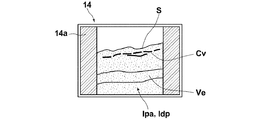
- FIG. 8 schematically shows a state in which the photoacoustic image Ipa and the Doppler image Idp are superimposed and displayed on the display screen 14a of the image display unit 14.
- the photoacoustic image Ipa shows a capillary vessel Cv and the like present in a portion relatively close to the epidermis S of the subject M.
- the Doppler image Idp shows a blood flow portion Ve or the like located deeper than the capillary blood vessel Cv.
- the two types of acoustic wave images described above are generated with a time interval.
- the photoacoustic image is generated after the Doppler image is generated.
- the image display control unit 27 includes a buffer memory that temporarily stores an image signal indicating each image.
- FIG. 2 is a schematic diagram for explaining this.
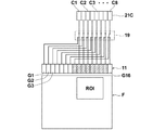
- the probe 11 is shown as a plurality of acoustic wave transducers G1 to G16 arranged in a one-dimensional array. That is, in this example, the probe 11 is shown as having 16 channels (channels).
- These acoustic wave transducers G1 to G16 are the transducer array 20 shown in FIG.
- FIG. 2 only some of the acoustic wave vibrators G1 to G16 are given numbers, but the acoustic wave vibrator G1, the acoustic wave vibrator G2, ... Are arranged in the order of acoustic wave transducers G16.
- F indicates an area where a Doppler image can be generated
- ROI indicates an area of interest set in the area F.
- the position of the probe 11 is shown as a relative position with respect to the region F, but this relative position corresponds to the positional relationship between the probe 11 and the subject M when generating the photoacoustic image. .
- reception circuit 21C conceptually shows the reception channel of the reception circuit 21 shown in FIG.
- the reception circuit 21 has eight reception channels C1 to C8.
- Reference numeral 19 denotes a multiplexer (see FIG. 1) interposed between the reception channel 21C and the probe 11.
- the signals emitted from the 16ch acoustic wave transducers G1 to G16 are received by the receiving circuit 21
- the signals emitted from the 8ch acoustic wave transducers G1 to G8 are first received by the 8ch reception channel.
- the signals are received by the receiving circuit 21 from C1 to C8.
- the multiplexer 19 is switched, and the signals emitted from the remaining 8ch acoustic wave transducers G9 to G16 are received by the receiving circuit 21 from the 8ch receiving channels C1 to C8.
- the multiplexer 19 when the photoacoustic image is generated, the multiplexer 19 is in a state as illustrated. In generating a photoacoustic image of one cross section of the subject M, the laser light L is emitted toward the subject M only once under this state. Thus, when the laser beam L is emitted once, only signals (photoacoustic wave detection signals) output from the 8ch acoustic wave transducers G4 to G11 are received by the receiving circuit 21 from the 8ch reception channels C1 to C8. The Thereafter, the multiplexer 19 is not switched, and the reception of the photoacoustic wave detection signal for generating a photoacoustic image of one cross section is completed.
- signals photoacoustic wave detection signals
- some of the 16-channel acoustic wave transducers G1 to G16 that is, the 8-channel acoustic wave transducers G1 to G3 and G12 to G16.
- the frame rate of photoacoustic image generation can be raised and the real-time property of a photoacoustic image can be improved.
- the acoustic wave vibrator serving as the reception aperture is indicated by hatching (the same applies to FIGS. 4 to 7).
- the 8-channel acoustic wave transducers G4 to G11 serving as the reception openings are determined based on the size and position of the region of interest ROI, which is a range in which the Doppler image signal is acquired. That is, in this example, the 8ch acoustic wave transducers G4 to G11 are set as the reception openings so that all the acoustic wave transducers arranged facing the entire region of interest ROI can be set as the reception openings.
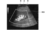
- a fan-shaped portion in a black background is an ultrasonic image such as a B-mode image, and a region of interest ROI that is a display range of a Doppler image is set therein.
- a blood flow portion is shown near the center of the region of interest ROI indicated by A, and there is an object to be displayed in a portion near the left and right ends of the region of interest indicated by B. Not done.
- the blood flow part is generally displayed.
- the photoacoustic image is used to display a blood vessel portion that absorbs light such as the laser light L and emits a photoacoustic wave. Accordingly, on the assumption that the region of interest ROI is set so as to include the blood flow part, the reception aperture of the probe 11 should be set so that at least the photoacoustic wave detection signal can be generated for this region of interest ROI. Even if the reception aperture is limited to a small size, the generated photoacoustic image can display the blood vessel portion as described above.
- the state of the multiplexer 19 is controlled by the control unit 34 based on information indicating the region of interest ROI. That is, in the present embodiment, the multiplexer 19 and the control unit 34 constitute reception aperture control means. Further, the region of interest setting unit 26 and the control unit 34 constitute means for setting the region of interest.
- FIG. 4 shows another example of the reception aperture setting of the probe 11.
- the size of the reception aperture is 8 ch as in the example of FIG. 2.
- the position of the region of interest ROI is different from that in the example of FIG. G15 is a reception aperture.
- the acoustic wave vibrator of the probe 11 is 128 ch
- the receiving channel of the receiving circuit 21 is 64 ch
- the repetition frequency of the laser light L is 10 Hz.
- Emitting laser beam L (first time) (2) Detect photoacoustic wave by 64ch acoustic wave vibrator (first time) (3) Emitting laser beam L (second time) (4) Photoacoustic wave is detected by the remaining 64ch acoustic wave transducer (second time) (5) It is necessary to emit the laser beam L twice, such as generating a photoacoustic image by the photoacoustic image generation unit 24 (see FIG. 1). Then, since the repetition frequency of emission of the laser light L is 10 Hz, the repetition frequency of photoacoustic image generation is 5 Hz (frame rate is 5 frames / second).
- the acoustic wave transducer of the probe 11 when the acoustic wave transducer of the probe 11 is originally 128 ch, if a half of 64 ch is used as a reception aperture, one photoacoustic image is generated.
- Emitting laser beam L first time
- Detect photoacoustic wave by 64ch acoustic wave vibrator first time
- the laser light L needs to be emitted only once, such as generation of a photoacoustic image by the photoacoustic image generation unit 24 (see FIG. 1).
- the repetition frequency of photoacoustic image generation can be set to 10 Hz (the frame rate is 10 frames / second) which is the same as the repetition frequency of emission of the laser light L.
- the region of interest ROI is often set to a partial region within a range where an ultrasonic image can be acquired by the probe 11. Therefore, it is often possible to generate a photoacoustic image that can display a desired portion such as a blood vessel portion even if the reception opening of the probe 11 is limited to about 1 ⁇ 2 of the reception opening that the probe 11 originally has. Therefore, according to the present invention, in many cases, the frame rate can be improved in the photoacoustic image generation as compared with the case where all the reception apertures originally provided in the probe 11 are used.
- the photoacoustic image has a shallow imageable area. That is, only a portion that is relatively close to the surface on the light irradiation side of the subject can be imaged. For this reason, the photoacoustic wave detection signal output by the acoustic wave transducer facing the portion of the Doppler image away from the region of interest ROI does not contribute to the improvement of image quality because the reception directivity angle of the acoustic wave transducer is deep. In many cases, the image quality of the photoacoustic image is deteriorated by increasing. On the other hand, in the example shown in FIG. 2 or the example shown in FIG. 4, a photoacoustic image is generated mainly based on a signal output from an acoustic wave transducer having a shallow reception directivity angle. Expected to improve image quality.
- the reception aperture may be widened within a range where the frame rate does not decrease.
- the reception aperture may be expanded to 64 ch.
- FIG. 5 another example of the reception aperture setting of the probe 11 is shown.
- all acoustic wave transducers arranged facing the entire region of interest ROI are set as reception openings.
- the reception apertures are set as in the above two examples, the number of the reception apertures becomes the reception channel of the reception circuit 21. It may be larger than the number of C1 to C8. In such a case, the frame rate for generating the photoacoustic image is lowered.
- the reception aperture In order to prevent such a situation, in the example of FIG. 5, only a part of the acoustic wave transducers among the acoustic transducers arranged facing the entire region of interest ROI are set as the reception aperture. That is, in this example, specifically, among the 14 acoustic wave vibrators that are arranged facing the entire region of interest ROI, eight acoustic wave vibrators G2, G4, G6, G8, G9, G11, G13 and Only G15 is a reception aperture. By doing this, the number of reception apertures of the probe 11 is made to coincide with the number of reception channels C1 to C8 of the reception circuit 21, and it is possible to prevent the frame rate of photoacoustic image generation from being lowered. This effect can be similarly obtained in the example of FIG.
- the setting of the reception aperture of the probe 11 as described above is an example according to the above-described actual apparatus, that is, the acoustic wave vibrator of the probe 11 is 128 ch, the reception channel of the reception circuit 21 is 64 ch, and the laser beam L is emitted.
- the repetition frequency of 10 Hz is 10 Hz.
- the repetition frequency of photoacoustic image generation can be set to 10 Hz, which is the same as the repetition frequency of emission of the laser light L.
- FIG. 6 shows still another example of the reception aperture setting of the probe 11.
- the example shown in FIG. 6 is basically the same as the example shown in FIG. 5 except that the arrangement of acoustic wave transducers serving as reception apertures is only partially different.
- a signal (photoacoustic signal) output from an acoustic wave transducer that is not set in the reception aperture among a plurality of acoustic transducers arranged opposite to the entire region of interest ROI. It is desirable to obtain the wave detection signal) by interpolating the signal output from the acoustic wave vibrator set in the reception aperture. If a photoacoustic image is generated based on the signal obtained by the interpolation, a photoacoustic image having no sense of incongruity in luminance and density distribution can be generated.
- the above interpolation may be performed on the signal after reconstructing the photoacoustic image, or may be performed on the signal before reconstruction.
- the photoacoustic image generation unit 24 shown in FIG. 1 may be provided with an interpolation function, and the photoacoustic image generation unit 24 may be used as an interpolation unit.
- FIG. 7 shows still another example of the reception aperture setting of the probe 11.
- the example shown in FIG. 7 is similar to the example of FIG. 5 and the example of FIG. 6 described above, of the acoustic wave vibrators G2 among the acoustic wave vibrators arranged facing the entire region of interest ROI, Only G4, G6, G7, G8, G9, G11 and G13 are set as reception apertures. Thereby, the same effect as in the example of FIG. 5 and the example of FIG. 6 can be obtained.
- the acoustic wave that becomes the reception aperture is selected by selecting the acoustic wave transducers G2, G4, G6, G7, G8, G9, G11, and G13 as the acoustic wave transducer that is the reception aperture.
- the vibrators are set to be in a more dense state at a position facing the center of the region of interest ROI than at a position facing the end of the region of interest ROI.
- the region of interest ROI is often set so that the blood flow portion and the like are near the center.
- the signal intensity of the photoacoustic wave detection signal is lower at the periphery of the region of interest ROI, and therefore may cause noise in the reconstructed photoacoustic image. Therefore, if the reception aperture of the probe 11 is set as in this example and the photoacoustic wave generated near the end of the region of interest ROI is not used much for photoacoustic image generation, The effect of improving the image quality of the photoacoustic image can be obtained.
- the number of channels of the probe 11 (the number of acoustic wave transducers) is 128 ch and the number of reception channels on the receiving circuit 21 side is 64 ch has been described in detail as an example. It is not limited to what you did.
- the number of channels of the probe 11 may be 196 ch, 256 ch, 512 ch, or the like, and the number of reception channels on the receiving circuit 21 side may be 128 ch, 256 ch, or the like.
- the multiplexer 19 may be provided with three or more input systems. Further, means other than the multiplexer 19 may be used as means for setting the receiving aperture of the probe 11.
Landscapes
- Health & Medical Sciences (AREA)
- Life Sciences & Earth Sciences (AREA)
- Engineering & Computer Science (AREA)
- Physics & Mathematics (AREA)
- Radar, Positioning & Navigation (AREA)
- Remote Sensing (AREA)
- General Health & Medical Sciences (AREA)
- Pathology (AREA)
- General Physics & Mathematics (AREA)
- Public Health (AREA)
- Surgery (AREA)
- Veterinary Medicine (AREA)
- Biophysics (AREA)
- Animal Behavior & Ethology (AREA)
- Biomedical Technology (AREA)
- Heart & Thoracic Surgery (AREA)
- Medical Informatics (AREA)
- Molecular Biology (AREA)
- Computer Networks & Wireless Communication (AREA)
- Acoustics & Sound (AREA)
- Radiology & Medical Imaging (AREA)
- Nuclear Medicine, Radiotherapy & Molecular Imaging (AREA)
- Chemical & Material Sciences (AREA)
- Analytical Chemistry (AREA)
- Biochemistry (AREA)
- Immunology (AREA)
- Optics & Photonics (AREA)
- Mechanical Engineering (AREA)
- Computer Vision & Pattern Recognition (AREA)
- Gynecology & Obstetrics (AREA)
- Ultra Sonic Daignosis Equipment (AREA)
Abstract
Priority Applications (4)
| Application Number | Priority Date | Filing Date | Title |
|---|---|---|---|
| JP2017566920A JP6475369B2 (ja) | 2016-02-08 | 2017-02-03 | 音響波画像生成装置および音響波画像生成方法 |
| CN201780010312.2A CN108601583B (zh) | 2016-02-08 | 2017-02-03 | 声波图像生成装置及声波图像生成方法 |
| EP17750182.2A EP3415097B1 (fr) | 2016-02-08 | 2017-02-03 | Dispositif de génération d'image d'onde acoustique et procédé de génération d'image d'onde acoustique |
| US16/054,466 US11119199B2 (en) | 2016-02-08 | 2018-08-03 | Acoustic wave image generation apparatus and acoustic wave image generation method |
Applications Claiming Priority (2)
| Application Number | Priority Date | Filing Date | Title |
|---|---|---|---|
| JP2016-022210 | 2016-02-08 | ||
| JP2016022210 | 2016-02-08 |
Related Child Applications (1)
| Application Number | Title | Priority Date | Filing Date |
|---|---|---|---|
| US16/054,466 Continuation US11119199B2 (en) | 2016-02-08 | 2018-08-03 | Acoustic wave image generation apparatus and acoustic wave image generation method |
Publications (1)
| Publication Number | Publication Date |
|---|---|
| WO2017138459A1 true WO2017138459A1 (fr) | 2017-08-17 |
Family
ID=59563067
Family Applications (1)
| Application Number | Title | Priority Date | Filing Date |
|---|---|---|---|
| PCT/JP2017/004072 Ceased WO2017138459A1 (fr) | 2016-02-08 | 2017-02-03 | Dispositif de génération d'image d'onde acoustique et procédé de génération d'image d'onde acoustique |
Country Status (5)
| Country | Link |
|---|---|
| US (1) | US11119199B2 (fr) |
| EP (1) | EP3415097B1 (fr) |
| JP (1) | JP6475369B2 (fr) |
| CN (1) | CN108601583B (fr) |
| WO (1) | WO2017138459A1 (fr) |
Families Citing this family (3)
| Publication number | Priority date | Publication date | Assignee | Title |
|---|---|---|---|---|
| WO2020110197A1 (fr) * | 2018-11-27 | 2020-06-04 | 株式会社島津製作所 | Appareil de recherche de défauts et procédé de recherche de défauts |
| JP7561569B2 (ja) * | 2020-10-22 | 2024-10-04 | 富士フイルム株式会社 | 超音波探触子 |
| CN113367660B (zh) * | 2021-06-09 | 2022-11-25 | 东北大学秦皇岛分校 | 一种光声多普勒流速测量装置及方法 |
Citations (7)
| Publication number | Priority date | Publication date | Assignee | Title |
|---|---|---|---|---|
| JP2012223367A (ja) * | 2011-04-20 | 2012-11-15 | Fujifilm Corp | 光音響画像生成装置及び方法 |
| JP2012254284A (ja) * | 2011-05-13 | 2012-12-27 | Fujifilm Corp | 断層画像生成装置、方法、及びプログラム |
| JP2013158531A (ja) | 2012-02-07 | 2013-08-19 | Canon Inc | 被検体情報取得装置及び被検体情報取得方法 |
| JP2014136102A (ja) * | 2013-01-18 | 2014-07-28 | Fujifilm Corp | ドプラ計測装置およびドプラ計測方法 |
| JP2014136103A (ja) | 2013-01-18 | 2014-07-28 | Fujifilm Corp | 光音響画像生成装置および光音響画像生成方法 |
| JP2015150238A (ja) * | 2014-02-14 | 2015-08-24 | オリンパス株式会社 | 超音波観測装置、超音波観測装置の作動方法、及び超音波観測装置の作動プログラム |
| JP2015181660A (ja) | 2014-03-24 | 2015-10-22 | キヤノン株式会社 | 被検体情報取得装置および乳房検査装置 |
Family Cites Families (28)
| Publication number | Priority date | Publication date | Assignee | Title |
|---|---|---|---|---|
| US4463608A (en) * | 1979-05-07 | 1984-08-07 | Yokogawa Hokushin Electric Corp. | Ultrasound imaging system |
| US6080107A (en) * | 1999-01-26 | 2000-06-27 | Hewlett-Packard Company | Methods for the use of contrast agents in ultrasonic imaging |
| JP4426478B2 (ja) * | 2005-02-18 | 2010-03-03 | アロカ株式会社 | 超音波診断装置 |
| US20090054763A1 (en) * | 2006-01-19 | 2009-02-26 | The Regents Of The University Of Michigan | System and method for spectroscopic photoacoustic tomography |
| CN101472520B (zh) * | 2006-06-23 | 2015-06-03 | 皇家飞利浦电子股份有限公司 | 组合光声和超声成像仪的时序控制器 |
| CN101563035B (zh) * | 2006-12-19 | 2012-08-08 | 皇家飞利浦电子股份有限公司 | 组合光声和超声成像系统 |
| EP2203733B1 (fr) * | 2007-10-25 | 2017-05-03 | Washington University in St. Louis | Microscopie photo-acoustique confocale présentant une résolution latérale optique |
| US20140142404A1 (en) * | 2008-10-23 | 2014-05-22 | The Washington University | Single-cell label-free photoacoustic flowoxigraphy in vivo |
| WO2010048258A1 (fr) * | 2008-10-23 | 2010-04-29 | Washington University In St. Louis | Tomographie photoacoustique à mode de réflexion utilisant une poutre en porte-à-faux supportée de façon souple |
| US9451884B2 (en) * | 2007-12-13 | 2016-09-27 | Board Of Trustees Of The University Of Arkansas | Device and method for in vivo detection of clots within circulatory vessels |
| CN102292029B (zh) * | 2008-07-18 | 2014-11-05 | 罗切斯特大学 | 用于c扫描光声成像的低成本设备 |
| JP5483905B2 (ja) * | 2009-03-03 | 2014-05-07 | キヤノン株式会社 | 超音波装置 |
| WO2011045734A1 (fr) * | 2009-10-16 | 2011-04-21 | Koninklijke Philips Electronics N.V. | Imagerie par ultrasons actifs basée sur l'emploi d'un agent de contraste photo-acoustique |
| US8879352B2 (en) * | 2010-01-25 | 2014-11-04 | The Arizona Board Of Regents On Behalf Of The University Of Arizona | Ultrasonic/photoacoustic imaging devices and methods |
| JPWO2011093108A1 (ja) * | 2010-02-01 | 2013-05-30 | パナソニック株式会社 | 超音波プローブおよびそれを用いた超音波検査装置 |
| US9999354B2 (en) * | 2011-01-21 | 2018-06-19 | National Research Council Of Canada | Biological tissue inspection method and system |
| JP5655021B2 (ja) * | 2011-03-29 | 2015-01-14 | 富士フイルム株式会社 | 光音響画像化方法および装置 |
| JP5713968B2 (ja) * | 2011-07-29 | 2015-05-07 | 富士フイルム株式会社 | 光音響画像生成装置及び音響波ユニット |
| WO2014070993A1 (fr) * | 2012-10-31 | 2014-05-08 | Cerebrosonics, Llc | Nouveau système de détection des embolies dans le cerveau utilisant un dispositif photoacoustique doppler transcrânien capable de mesurer la vascularisation et la perfusion |
| EP2740410B1 (fr) | 2012-12-04 | 2018-05-16 | Canon Kabushiki Kaisha | Dispositif d'acquisition d'informations de sujet, procédé de commande de dispositif d'acquisition d'informations de sujet et programme associé |
| KR20140084828A (ko) * | 2012-12-27 | 2014-07-07 | 삼성전자주식회사 | 광음향 프로브 및 이를 포함하는 광음향 장치 |
| US20140194740A1 (en) * | 2013-01-07 | 2014-07-10 | Cerebrosonics, Llc | Emboli detection in the brain using a transcranial doppler photoacoustic device capable of vasculature and perfusion measurement |
| EP2754388B1 (fr) * | 2013-01-15 | 2020-09-09 | Helmholtz Zentrum München Deutsches Forschungszentrum für Gesundheit und Umwelt GmbH | Système et procédé pour imagerie opto-acoustique à haut débit de meilleure qualité d'un objet |
| US20140276059A1 (en) * | 2013-03-12 | 2014-09-18 | Volcano Corporation | Externally imaging a body structure within a patient |
| KR101533591B1 (ko) * | 2013-07-08 | 2015-07-06 | 삼성메디슨 주식회사 | 의료 영상 장치 및 의료 영상 제공 방법 |
| WO2015077088A1 (fr) * | 2013-11-22 | 2015-05-28 | Massachusetts Institute Of Technology | Système et procédé pour ultrason sans contact |
| KR102268668B1 (ko) * | 2014-03-12 | 2021-06-24 | 삼성메디슨 주식회사 | 대상체에 대한 복수의 상이한 영상들을 디스플레이하는 방법 및 장치 |
| EP4249953A3 (fr) * | 2014-09-04 | 2023-11-22 | Samsung Medison Co., Ltd. | Sonde à ultrasons et son procédé de fonctionnement |
-
2017
- 2017-02-03 WO PCT/JP2017/004072 patent/WO2017138459A1/fr not_active Ceased
- 2017-02-03 CN CN201780010312.2A patent/CN108601583B/zh active Active
- 2017-02-03 EP EP17750182.2A patent/EP3415097B1/fr active Active
- 2017-02-03 JP JP2017566920A patent/JP6475369B2/ja active Active
-
2018
- 2018-08-03 US US16/054,466 patent/US11119199B2/en active Active
Patent Citations (7)
| Publication number | Priority date | Publication date | Assignee | Title |
|---|---|---|---|---|
| JP2012223367A (ja) * | 2011-04-20 | 2012-11-15 | Fujifilm Corp | 光音響画像生成装置及び方法 |
| JP2012254284A (ja) * | 2011-05-13 | 2012-12-27 | Fujifilm Corp | 断層画像生成装置、方法、及びプログラム |
| JP2013158531A (ja) | 2012-02-07 | 2013-08-19 | Canon Inc | 被検体情報取得装置及び被検体情報取得方法 |
| JP2014136102A (ja) * | 2013-01-18 | 2014-07-28 | Fujifilm Corp | ドプラ計測装置およびドプラ計測方法 |
| JP2014136103A (ja) | 2013-01-18 | 2014-07-28 | Fujifilm Corp | 光音響画像生成装置および光音響画像生成方法 |
| JP2015150238A (ja) * | 2014-02-14 | 2015-08-24 | オリンパス株式会社 | 超音波観測装置、超音波観測装置の作動方法、及び超音波観測装置の作動プログラム |
| JP2015181660A (ja) | 2014-03-24 | 2015-10-22 | キヤノン株式会社 | 被検体情報取得装置および乳房検査装置 |
Non-Patent Citations (1)
| Title |
|---|
| See also references of EP3415097A4 |
Also Published As
| Publication number | Publication date |
|---|---|
| JP6475369B2 (ja) | 2019-02-27 |
| EP3415097A1 (fr) | 2018-12-19 |
| EP3415097A4 (fr) | 2019-01-23 |
| CN108601583A (zh) | 2018-09-28 |
| US20180341011A1 (en) | 2018-11-29 |
| EP3415097B1 (fr) | 2020-07-15 |
| US11119199B2 (en) | 2021-09-14 |
| JPWO2017138459A1 (ja) | 2018-07-05 |
| CN108601583B (zh) | 2021-05-11 |
Similar Documents
| Publication | Publication Date | Title |
|---|---|---|
| JP5661451B2 (ja) | 被検体情報取得装置及び被検体情報取得方法 | |
| US11083376B2 (en) | Photoacoustic measurement device and signal processing method of photoacoustic measurement device | |
| EP1561424A1 (fr) | Procédé et dispositif pour l'imagerie diagnostique non-invasive | |
| WO2012140865A1 (fr) | Appareil d'acquisition d'informations relatives à un objet et procédé d'acquisition d'informations relatives à un objet | |
| JP5863345B2 (ja) | 被検体情報取得装置および被検体情報取得方法 | |
| JP6132466B2 (ja) | 被検体情報取得装置及び被検体情報取得方法 | |
| JP2010022816A (ja) | 超音波探触子、該超音波探触子を備えた光音響・超音波システム並びに検体イメージング装置 | |
| JP6049215B2 (ja) | 光音響計測装置並びにそれに利用される信号処理装置および信号処理方法 | |
| JP2011245277A (ja) | 表示データ取得装置及び表示データ取得方法 | |
| EP2740410A1 (fr) | Dispositif d'acquisition d'informations de sujet, procédé de commande de dispositif d'acquisition d'informations de sujet et programme associé | |
| US11119199B2 (en) | Acoustic wave image generation apparatus and acoustic wave image generation method | |
| JP2019088346A (ja) | 光音響装置および被検体情報取得方法 | |
| JP2018061725A (ja) | 被検体情報取得装置および信号処理方法 | |
| US11344204B2 (en) | Photoacoustic measurement probe and probe unit and photoacoustic measurement apparatus including the same | |
| US11399719B2 (en) | Probe for photoacoustic measurement and photoacoustic measurement apparatus including same | |
| WO2019044594A1 (fr) | Dispositif de génération d'images photoacoustiques et procédé d'acquisition d'images | |
| JPWO2017135167A1 (ja) | 光音響画像生成システム、装置、及び方法 | |
| WO2019044593A1 (fr) | Appareil et procédé de génération d'image photoacoustique | |
| JP6643108B2 (ja) | 被検体情報取得装置および被検体情報取得方法 | |
| JP2019155004A (ja) | 光音響装置および被検体情報取得方法 | |
| JP6513121B2 (ja) | 処理装置、被検体情報取得装置、光音響画像の表示方法、及びプログラム | |
| JP2019136520A (ja) | 処理装置、光音響画像の表示方法、及びプログラム | |
| JP2014023680A (ja) | 被検体情報取得装置およびその制御方法ならびに提示方法 | |
| WO2018235781A1 (fr) | Dispositif de génération d'images d'ondes acoustiques et procédé d'analyse d'images opto-acoustiques | |
| JP2013173060A (ja) | 超音波探触子、該超音波探触子を備えた光音響・超音波システム並びに検体イメージング装置 |
Legal Events
| Date | Code | Title | Description |
|---|---|---|---|
| 121 | Ep: the epo has been informed by wipo that ep was designated in this application |
Ref document number: 17750182 Country of ref document: EP Kind code of ref document: A1 |
|
| ENP | Entry into the national phase |
Ref document number: 2017566920 Country of ref document: JP Kind code of ref document: A |
|
| NENP | Non-entry into the national phase |
Ref country code: DE |
|
| WWE | Wipo information: entry into national phase |
Ref document number: 2017750182 Country of ref document: EP |
|
| ENP | Entry into the national phase |
Ref document number: 2017750182 Country of ref document: EP Effective date: 20180910 |