WO2017138533A1 - 副鼻腔に対する挿入機器アッセンブリ - Google Patents
副鼻腔に対する挿入機器アッセンブリ Download PDFInfo
- Publication number
- WO2017138533A1 WO2017138533A1 PCT/JP2017/004422 JP2017004422W WO2017138533A1 WO 2017138533 A1 WO2017138533 A1 WO 2017138533A1 JP 2017004422 W JP2017004422 W JP 2017004422W WO 2017138533 A1 WO2017138533 A1 WO 2017138533A1
- Authority
- WO
- WIPO (PCT)
- Prior art keywords
- distal end
- sheath
- guide pipe
- endoscope
- insertion portion
- Prior art date
- Legal status (The legal status is an assumption and is not a legal conclusion. Google has not performed a legal analysis and makes no representation as to the accuracy of the status listed.)
- Ceased
Links
Images















Classifications
-
- A—HUMAN NECESSITIES
- A61—MEDICAL OR VETERINARY SCIENCE; HYGIENE
- A61B—DIAGNOSIS; SURGERY; IDENTIFICATION
- A61B1/00—Instruments for performing medical examinations of the interior of cavities or tubes of the body by visual or photographical inspection, e.g. endoscopes; Illuminating arrangements therefor
- A61B1/233—Instruments for performing medical examinations of the interior of cavities or tubes of the body by visual or photographical inspection, e.g. endoscopes; Illuminating arrangements therefor for the nose, i.e. nasoscopes, e.g. testing of patency of Eustachian tubes
-
- A—HUMAN NECESSITIES
- A61—MEDICAL OR VETERINARY SCIENCE; HYGIENE
- A61B—DIAGNOSIS; SURGERY; IDENTIFICATION
- A61B1/00—Instruments for performing medical examinations of the interior of cavities or tubes of the body by visual or photographical inspection, e.g. endoscopes; Illuminating arrangements therefor
- A61B1/00002—Operational features of endoscopes
- A61B1/00043—Operational features of endoscopes provided with output arrangements
- A61B1/00045—Display arrangement
- A61B1/0005—Display arrangement combining images e.g. side-by-side, superimposed or tiled
-
- A—HUMAN NECESSITIES
- A61—MEDICAL OR VETERINARY SCIENCE; HYGIENE
- A61B—DIAGNOSIS; SURGERY; IDENTIFICATION
- A61B1/00—Instruments for performing medical examinations of the interior of cavities or tubes of the body by visual or photographical inspection, e.g. endoscopes; Illuminating arrangements therefor
- A61B1/00064—Constructional details of the endoscope body
- A61B1/00066—Proximal part of endoscope body, e.g. handles
-
- A—HUMAN NECESSITIES
- A61—MEDICAL OR VETERINARY SCIENCE; HYGIENE
- A61B—DIAGNOSIS; SURGERY; IDENTIFICATION
- A61B1/00—Instruments for performing medical examinations of the interior of cavities or tubes of the body by visual or photographical inspection, e.g. endoscopes; Illuminating arrangements therefor
- A61B1/00131—Accessories for endoscopes
- A61B1/00135—Oversleeves mounted on the endoscope prior to insertion
-
- A—HUMAN NECESSITIES
- A61—MEDICAL OR VETERINARY SCIENCE; HYGIENE
- A61B—DIAGNOSIS; SURGERY; IDENTIFICATION
- A61B1/00—Instruments for performing medical examinations of the interior of cavities or tubes of the body by visual or photographical inspection, e.g. endoscopes; Illuminating arrangements therefor
- A61B1/00131—Accessories for endoscopes
- A61B1/0014—Fastening element for attaching accessories to the outside of an endoscope, e.g. clips, clamps or bands
-
- A—HUMAN NECESSITIES
- A61—MEDICAL OR VETERINARY SCIENCE; HYGIENE
- A61B—DIAGNOSIS; SURGERY; IDENTIFICATION
- A61B1/00—Instruments for performing medical examinations of the interior of cavities or tubes of the body by visual or photographical inspection, e.g. endoscopes; Illuminating arrangements therefor
- A61B1/00147—Holding or positioning arrangements
- A61B1/00154—Holding or positioning arrangements using guiding arrangements for insertion
-
- A—HUMAN NECESSITIES
- A61—MEDICAL OR VETERINARY SCIENCE; HYGIENE
- A61B—DIAGNOSIS; SURGERY; IDENTIFICATION
- A61B1/00—Instruments for performing medical examinations of the interior of cavities or tubes of the body by visual or photographical inspection, e.g. endoscopes; Illuminating arrangements therefor
- A61B1/00163—Optical arrangements
- A61B1/00172—Optical arrangements with means for scanning
-
- A—HUMAN NECESSITIES
- A61—MEDICAL OR VETERINARY SCIENCE; HYGIENE
- A61B—DIAGNOSIS; SURGERY; IDENTIFICATION
- A61B1/00—Instruments for performing medical examinations of the interior of cavities or tubes of the body by visual or photographical inspection, e.g. endoscopes; Illuminating arrangements therefor
- A61B1/005—Flexible endoscopes
-
- A—HUMAN NECESSITIES
- A61—MEDICAL OR VETERINARY SCIENCE; HYGIENE
- A61B—DIAGNOSIS; SURGERY; IDENTIFICATION
- A61B1/00—Instruments for performing medical examinations of the interior of cavities or tubes of the body by visual or photographical inspection, e.g. endoscopes; Illuminating arrangements therefor
- A61B1/012—Instruments for performing medical examinations of the interior of cavities or tubes of the body by visual or photographical inspection, e.g. endoscopes; Illuminating arrangements therefor characterised by internal passages or accessories therefor
- A61B1/015—Control of fluid supply or evacuation
-
- A—HUMAN NECESSITIES
- A61—MEDICAL OR VETERINARY SCIENCE; HYGIENE
- A61B—DIAGNOSIS; SURGERY; IDENTIFICATION
- A61B1/00—Instruments for performing medical examinations of the interior of cavities or tubes of the body by visual or photographical inspection, e.g. endoscopes; Illuminating arrangements therefor
- A61B1/06—Instruments for performing medical examinations of the interior of cavities or tubes of the body by visual or photographical inspection, e.g. endoscopes; Illuminating arrangements therefor with illuminating arrangements
- A61B1/07—Instruments for performing medical examinations of the interior of cavities or tubes of the body by visual or photographical inspection, e.g. endoscopes; Illuminating arrangements therefor with illuminating arrangements using light-conductive means, e.g. optical fibres
-
- A—HUMAN NECESSITIES
- A61—MEDICAL OR VETERINARY SCIENCE; HYGIENE
- A61B—DIAGNOSIS; SURGERY; IDENTIFICATION
- A61B1/00—Instruments for performing medical examinations of the interior of cavities or tubes of the body by visual or photographical inspection, e.g. endoscopes; Illuminating arrangements therefor
- A61B1/00064—Constructional details of the endoscope body
- A61B1/00071—Insertion part of the endoscope body
- A61B1/0008—Insertion part of the endoscope body characterised by distal tip features
Definitions
- This invention relates to an insertion device assembly for the paranasal sinuses.
- USP 7,559,925 B discloses a treatment instrument in which a light guide fiber is inserted into a guide pipe.
- This treatment instrument guides the light guide fiber to the sinuses while visually observing light emitted from the tip of the light guide fiber through the skin and bones of the patient. That is, the position of the tip of the light guide fiber in the nasal cavity is estimated based on the light emitted from the tip of the light guide fiber.
- the shape of the path leading to the sinuses and the size of the sinus opening (entrance) vary depending on the patient.
- a plurality of openings in various sinuses may be adjacent to a target opening around the sinus. Therefore, as in the treatment tool disclosed in USP 5597,559,925 ⁇ B, when the light emitted from the tip of the light guide fiber is guided to the sinuses, access to the sinuses is an indirect confirmation from the outside. The route to the nasal cavity cannot be directly recognized.
- An object of the present invention is to provide an insertion device assembly that can be accessed by observing the target position of the sinuses reliably.
- An insertion device assembly for a paranasal sinus includes a guide pipe main body, a guide pipe bending portion provided on a distal end side of the guide pipe main body, and a guide provided on a distal end of the guide pipe bending portion.
- a sheath distal end opening, an insertion portion of an endoscope that is inserted into the sheath so as to be able to advance and retreat, and the sheath distal end opening and the distal end of the insertion portion of the endoscope are passed through the guide pipe bending portion. And the distal end of the insertion portion of the endoscope can protrude from the guide pipe distal end opening. And a mirror operation unit.
- FIG. 1A is a schematic view showing a treatment system according to the first embodiment.
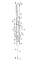
- FIG. 1B is a schematic front view showing a state in which the insertion device assembly of the treatment system is viewed from the direction of arrow 1B in FIG. 1A.
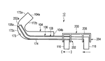
- FIG. 2A is a schematic top view showing a state in which the insertion device assembly of the treatment system is viewed from the direction of the arrow 2A in FIG. 1A.
- FIG. 2B is a schematic longitudinal sectional view of the insertion device assembly taken along the line 2B-2B in FIG. 2A.
- FIG. 3 is a schematic longitudinal sectional view showing the distal end portion of the insertion portion of the endoscope of the insertion device assembly of the treatment system according to the first embodiment.
- FIG. 1A is a schematic view showing a treatment system according to the first embodiment.
- FIG. 1B is a schematic front view showing a state in which the insertion device assembly of the treatment system is viewed from the direction of arrow 1B in FIG. 1A.
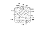
- FIG. 4A is a schematic cross-sectional view of the insertion device assembly taken along line 4A-4A in FIG. 2B.
- FIG. 4B is a schematic cross-sectional view of the insertion device assembly taken along line 4B-4B in FIG. 2B.
- FIG. 5A is an enlarged schematic view showing the vicinity of the connecting pipe of the insertion device assembly at the position indicated by reference numeral 5A in FIG. 2B.
- FIG. 5B is an enlarged schematic view showing the vicinity of the first operation element of the insertion device assembly at the position indicated by reference numeral 5B in FIG. 2B.
- FIG. 6 is a schematic longitudinal sectional view showing a sheath of the insertion device assembly of the treatment system according to the first embodiment.
- FIG. 7 is a schematic longitudinal sectional view showing a guide pipe of the insertion device assembly of the treatment system according to the first embodiment.
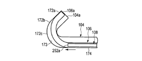
- FIG. 8A shows that the distal end of the sheath and the insertion end of the endoscope are connected to the bent portion of the guide pipe of the insertion device assembly of the treatment system according to the first embodiment by using the interlocking portion.
- It is a schematic diagram showing a state in which the distal end of the sheath and the distal end of the insertion portion of the endoscope are directed to the guide portion formed continuously in the bending portion while being brought into contact with the distal surface.
- FIG. 8B shows that the distal end of the sheath and the distal end of the insertion portion of the endoscope are passed through the bending portion of the curved pipe of the guide pipe of the insertion device assembly of the treatment system according to the first embodiment using the interlocking portion.
- FIG. 8C shows the first and first portions after passing the distal end of the sheath and the distal end of the insertion portion of the endoscope with respect to the bent portion of the curved pipe of the guide pipe of the insertion device assembly of the treatment system according to the first embodiment.
- FIG. 8D shows the first and second operations by passing the distal end of the sheath and the distal end of the insertion portion of the endoscope through the bent portion of the curved pipe of the guide pipe of the insertion device assembly of the treatment system according to the first embodiment.
- FIG. 8D shows the state which protruded the front-end
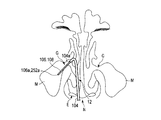
- FIG. 9A shows the positional relationship of the maxillary sinus with respect to the nose, and the distal end portion of the guide pipe of the insertion device assembly is arranged at the entrance of the maxillary sinus so that the distal end of the sheath and / or the endoscope from the distal end of the guide pipe. It is the schematic which shows the state which made the front-end
- FIG. 9B shows the positional relationship of the maxillary sinus with respect to the nose, and the distal end of the guide pipe of the insertion device assembly is disposed at the entrance of the maxillary sinus, so that the distal end of the sheath and / or the endoscope from the distal end of the guide pipe.
- FIG. 10A shows the insertion device assembly of the treatment system according to the first embodiment, by passing the distal end of the sheath through the bent portion of the curved pipe of the guide pipe without using the interlocking portion, and inserting the endoscope. It is a schematic diagram which shows the state which has arrange
- FIG. 10B shows the insertion device assembly of the treatment system according to the first embodiment when the distal end of the sheath is passed through the bent portion of the curved pipe of the guide pipe without using the interlocking portion.
- FIG. 11 shows that the bending portion of the curved pipe of the guide pipe of the insertion device assembly of the treatment system according to the modification of the first embodiment passes through the distal end of the sheath and the insertion portion of the endoscope using the interlocking portion.
- FIG. 12A shows the bending portion of the curved pipe of the guide pipe of the insertion device assembly of the treatment system according to the modification of the first embodiment using the interlocking portion and passing through the distal end of the sheath and the insertion portion of the endoscope.
- FIG. 5 is a schematic diagram showing a state immediately before the click mechanism adds a click feeling while showing the state in which the distal end of the sheath and the distal end of the insertion portion of the endoscope are arranged between the bent portion and the distal end of the guide pipe.
- FIG. 12B shows the bending portion of the bent pipe of the guide pipe of the insertion device assembly of the treatment system according to the modification of the first embodiment using the interlocking portion and passing through the distal end of the sheath and the insertion portion of the endoscope.
- FIG. 5 is a schematic diagram showing a state immediately after the click mechanism adds a click feeling while showing the state where the distal end of the sheath and the distal end of the insertion portion of the endoscope are arranged between the bent portion and the distal end of the guide pipe.
- FIG. 13A shows that the distal end of the sheath and the distal end of the insertion portion of the endoscope are passed through the bending portion of the curved pipe of the guide pipe of the insertion device assembly of the treatment system according to the second embodiment by using the interlocking portion.
- FIG. 13B shows the interlocking of the interlocking portion after passing the distal end of the sheath and the distal end of the insertion portion of the endoscope with respect to the bent portion of the guide pipe of the insertion device assembly of the treatment system according to the second embodiment.
- FIG. 13B shows the state which canceled the state and made it the non-interlocking state, and protruded the front-end
- FIG. 14A shows the distal end of the sheath and the distal end of the insertion portion of the endoscope using the interlocking portion with respect to the bent portion of the curved pipe of the guide pipe of the insertion device assembly of the treatment system according to the first modification of the second embodiment.
- FIG. 14B shows a state where the distal end of the sheath and the distal end of the insertion portion of the endoscope are passed through the bent portion of the bent pipe of the guide pipe of the insertion device assembly of the treatment system according to the first modification of the second embodiment.
- FIG. 5 is a schematic diagram showing a state in which the interlocking state of the interlocking part is released and the interlocking part is brought into a non-interlocking state so that the distal end of the insertion part of the endoscope projects from the distal end of the sheath.
- FIG. 15A shows the distal end of the sheath and the distal end of the insertion portion of the endoscope using the interlocking portion with respect to the bent portion of the curved pipe of the guide pipe of the insertion device assembly of the treatment system according to the second modification of the second embodiment.
- FIG. 15B shows a state in which the distal end of the sheath and the distal end of the insertion portion of the endoscope are passed through the bent portion of the curved pipe of the guide pipe of the insertion device assembly of the treatment system according to the second modification of the second embodiment.
- FIG. 5 is a schematic diagram showing a state in which the interlocking state of the interlocking part is released and the interlocking part is brought into a non-interlocking state so that the distal end of the insertion part of the endoscope projects from the distal end of the sheath.
- FIG. 16A shows the distal end of the sheath and the endoscope in conjunction with the bending of the bent pipe of the guide pipe of the insertion device assembly of the treatment system according to the third embodiment in order to operate the operator of the endoscope.
- It is a schematic diagram which shows the state which passed the front-end
- FIG. 16B shows the distal end of the sheath and the endoscope in conjunction with the bending of the bent pipe of the guide pipe of the insertion device assembly of the treatment system according to the third embodiment in order to operate the operator of the endoscope.
- FIG. 16C shows the distal end of the sheath and the endoscope in conjunction with the bending of the bent pipe of the guide pipe of the insertion device assembly of the treatment system according to the third embodiment in order to operate the operator of the endoscope.
- a treatment system (endoscope system) 10 includes an insertion device assembly 12, a controller 14, and a monitor 16 for the paranasal sinuses.
- a suction source 22 and a liquid supply source (liquid supply source) 24 can be connected to the insertion device assembly 12.
- a switching valve 28 such as a three-way stopcock is disposed between the end of the tube 26 extending from the insertion device assembly 12 and the suction source 22 and the liquid supply source 24. Therefore, the user can selectively use the suction source 22 and the liquid supply source 24 for the insertion device assembly 12 by operating the switching valve 28.
- an open / close valve 30 such as a three-way stopcock to which the syringe 32 can be detachably connected is preferably disposed between the switching valve 28 and the liquid supply source 24, for example, for medication. It is.
- the switching valve 28 and the on-off valve 30 may be electromagnetically operated by switching a switch (not shown) connected to the controller 14 or may be manually switched.
- the liquid supplied from the liquid supply source 24 can be selected as appropriate.
- the liquid supply source 24 can supply physiological saline for cleaning the affected part such as the inside of the sinuses inside the nose N, for example, the inside of the maxillary sinus M (see FIGS. 9A and 9B).
- a chemical solution can be supplied for the treatment of the affected area.
- steroids and antibacterial agents are mainly administered.
- a temperature-responsive gel or the like that increases in viscosity when the temperature reaches a body temperature may be used for the drug solution in order to extend the residence time of the drug solution in the affected area.
- the suction source 22 for example, a suction device disposed on the wall of the operating room can be used as it is. By operating the suction source 22, it is possible to remove viscous substances present in the paranasal sinuses such as the maxillary sinus M and the affected area in the nasal cavity. When the affected area and its surroundings are washed with physiological saline, the washing liquid can be removed together with the viscous substance.
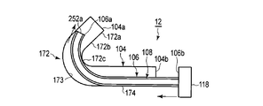
- the insertion device assembly 12 includes a handle unit 102, a guide pipe 104, a sheath 106, and an endoscope 108.
- the endoscope 108 includes an insertion portion 242 that is inserted into the sheath 106 so as to be able to advance and retract, a bend stopper 244, a support portion 246, and a cable 248.
- the insertion portion 242 has a length of about 200 mm, for example, and is formed so as to protrude about 100 mm, for example, with respect to a distal end (tip opening) 104a of a guide pipe 104 described later.
- the insertion portion 242 preferably has a small outer diameter of about 1 mm to 2 mm, and particularly preferably about 1.4 mm.
- the endoscope 108 may be of any type such as a fiber type, for example, an imaging element type such as a CCD or a CMOS. A scanning type is preferably used. By using such an endoscope 108, the outer diameter of the insertion portion 242 can be reduced and a good image quality can be obtained.
- the scanning endoscope 108 is well known and will not be described in detail, but the internal structure of the distal end portion 242a of the insertion portion 242 is formed as shown in FIG.
- the insertion portion 242 of the scanning endoscope 108 includes a hard distal end portion 252, a flexible tube 254, an illumination window 256, an actuator 258, an illumination fiber 260, and a plurality of light receiving components.
- the illumination window 256, the actuator 258, the illumination fiber 260, and the plurality of light receiving fibers 262 form an observation optical system 264.
- an observation optical system 264 is disposed inside the insertion portion 242.
- the actuator 258, the illumination fiber 260, and the plurality of light receiving fibers 262 are optically and / or electrically connected to the controller 14 shown in FIG. 1A, respectively.
- the controller 14 shown in FIG. 1A controls the observation optical system 264 of the endoscope 108.
- the controller 14 controls the operation of the actuator 258.
- the controller 14 has a light source (not shown) such as white light, and appropriately enters light for observation into the illumination fiber 260.
- the controller 14 images the light received by the light receiving fiber 262.
- the distal end rigid portion 252, the illumination window 256, the actuator 258, the distal end of the illumination fiber 260, and the distal ends of the plurality of light receiving fibers 262 are disposed at the distal end portion 242 a of the insertion portion 242.
- the tip of the illumination window 256 and the light receiving fiber 262 is fixed to the tip surface (tip) 252a of the tip hard portion 252.
- the ends of the plurality of light receiving fibers 262 are fixed around the illumination window 256 at an appropriate interval.
- An actuator 258 is disposed on the proximal end side of the illumination window 256 in the distal end hard portion 252.
- the actuator 258 supports the distal end portion of the illumination fiber 260 (the most proximal portion with respect to the distal end).
- the actuator 258 is swung, for example, in a spiral shape by the controller 14. Therefore, the tip 260 a of the illumination fiber 260 is swung in a spiral shape according to the operation of the actuator 258. Accordingly, the illumination light is scanned in a spiral shape on the surface of the subject through the tip of the illumination fiber 260 and the illumination window 256.
- the plurality of light receiving fibers 262 receive return light from the subject and guide the light to the controller 14.
- the controller 14 shown in FIG. 1A images the light received by the plurality of light receiving fibers 262 and displays the imaged image on the monitor 16 connected to the controller 14.
- a flexible tube 254 extends toward the proximal end side of the distal end hard portion 252.
- the length of the distal end hard portion 252 is, for example, about 10 mm.
- the flexible tube 254 occupies most of the entire length of the insertion portion 242. In other words, most of the insertion portion 242 is formed as a portion having flexibility.
- a bend stopper 244 is fixed to the proximal end of the flexible tube 254.
- a support portion 246 is fixed to the proximal end of the bend stopper 244.
- a cable 248 is fixed to the base end of the support portion 246. The proximal end of the cable 248 is connected to the controller 14.
- the handle unit 102 is gripped by the user and operated appropriately.
- the insertion portion 242 of the endoscope 108, the sheath 106, and the guide pipe 104 are arranged in this order from the inner side to the outer side of the central axis C.
- the handle unit 102 includes a main body 112, a guide rail 114, a first operating element (sheath operating part) 116 that moves the sheath 106, and a second operating element (supporting and moving the insertion part 242 of the endoscope 108). Endoscope operation unit) 118.
- the main body 112 defines a longitudinal axis L by a distal end 112a and a proximal end 112b.
- the main body 112 has a substantially U-shaped cross section. The upper side of the main body 112 is open.
- the guide rail 114 is fixed to the distal end 112a and the proximal end 112b of the main body 112, respectively.
- the guide rail 114 is formed by a rod or pipe that connects the front end 112a and the base end 112b of the main body 112 straightly.
- the guide rail 114 is formed of a rigid material such as a stainless steel material.
- the number of guide rails 114 may be one, but it is preferable that the guide rails 114 are formed in plural, such as two (one pair) parallel to each other.
- a connecting pipe 120 to which the base end of the guide pipe 104 is connected is fixed to the distal end 112a of the main body 112.
- An O-ring 120a is disposed between the inner peripheral surface of the connection pipe 120 and the outer peripheral surface of the inner pipe 156 described later of the sheath 106.
- the O-ring 120a exhibits an appropriate frictional force between its inner peripheral surface and the outer peripheral surface of the inner pipe 156 of the sheath 106. For this reason, the sheath 106 can be rotated around the central axis C and moved along the central axis C by a user operation, but free movement is suppressed.
- the O-ring 120a is prevented from dropping from the proximal end side of the connecting pipe 120 by the pressing member 120b.
- FIGS. 2A, 2B, 4A, 4B, 5A, and 5B there is a first movement between the distal end 112a and the proximal end 112b of the main body 112 of the handle unit 102 along the guide rail 114.
- 1 and 2nd holders 122 and 124 are arranged.
- the first holder 122 is close to the distal end 112 a of the main body 112
- the second holder 124 is close to the proximal end 112 b of the main body 112.
- the first and second holders 122 and 124 can be moved toward and away from each other along the guide rail 114.
- the first holder 122 supports a T-shaped pipe 132 that communicates between the outer peripheral surface of the insertion portion 242 of the endoscope 108 and the inner peripheral surface of the sheath 106. ing.
- a first rotor 134 that is rotatable around the central axis C is disposed at the tip of the T-shaped pipe 132.
- the first operator 116 is formed by the first holder 122, the T-shaped pipe 132, and the first rotor 134.
- the first operation element 116 can move the sheath 106 in the axial direction with respect to the guide pipe 104 and the insertion portion 242 and can rotate around the axis. For this reason, the first operator 116 can move the sheath 106 with respect to the guide pipe 104 and the insertion portion 242.
- the T-type pipe 132 is connected to a joint 136 that communicates with the central axis C of the T-type pipe 132 and the first rotor 134 through a pipe line 132a.
- the joint 136 protrudes from the opening 112 c of the main body 112 of the handle unit 102.
- a suction source 22, a liquid supply source 24, a switching valve 28, and an on-off valve 30 shown in FIG. 1A are connected to the joint 136.
- O-rings 138a and 138b are arranged.
- the O-ring 138 b is prevented from falling off from the proximal end side of the T-shaped pipe 132 by the pressing member 140. For this reason, when gas or liquid is supplied from the joint 136, the gas or liquid can be guided toward the tip of the T-shaped pipe 132.
- the O-ring 138b exerts an appropriate frictional force between its inner peripheral surface and the outer peripheral surface of the insertion portion 242 of the endoscope 108. For this reason, although the insertion part 242 of the endoscope 108 can be rotated around the axis of the central axis C and moved along the central axis C by a user's operation, the free movement is suppressed. ing. Further, here, the frictional force between the inner peripheral surface of the O-ring 138b and the outer peripheral surface of the insertion portion 242 of the endoscope 108 is changed by the movement of the first operator 116, that is, the movement of the insertion portion 242. It is assumed that the operator 118 is set so as not to move unintentionally.
- the O-ring 138a exhibits an appropriate frictional force between the outer peripheral surface and the first rotor 134. For this reason, the first rotor 134 can be rotated around the axis of the central axis C and moved along the central axis C by a user's operation, but free movement is suppressed.
- first holder 122 includes the first rotor 134
- a mechanism for rotating the sheath 106 is not necessarily required.
- the sheath 106 shown in FIG. 6 has an inner diameter that allows the insertion portion 242 to be inserted into the insertion portion 242 so that the distal end 252a of the insertion portion 242 can protrude from a sheath distal end opening (tip) 106a provided at the distal end.
- the sheath 106 is inserted from the proximal end side opening 104b of the guide pipe 104 through the straight pipe 174 of the guide pipe 104 to the curved pipe 172 and the distal end opening 104a so as to advance and retreat. For this reason, the sheath 106 is inserted inside the guide pipe 104 so that the tip 106a can protrude from a tip 104a provided on the tip side of a bending portion 172c described later of the guide pipe 104.
- the sheath 106 includes a sheath body 152, a sheath holder 154, and an inner pipe 156 in order from the distal end side toward the proximal end side.
- the sheath body 152 is an elastically deformable resin material having a thickness of, for example, about 0.1 mm and is formed in a tubular shape.
- a mesh tube (not shown) called a blade is embedded.
- the sheath main body 152 according to this embodiment is stronger than the resin body. Therefore, the sheath body 152 of the sheath 106 is thin and has a good rotational followability around the axis of the central axis C, is easily bent, and is not easily bent so as to secure a hollow portion inside thereof. .
- the sheath main body 152 is formed so that it is harder to bend than the flexible tube 254 of the insertion part 242 of the endoscope 108 shown in FIG. Therefore, when the entire distal end hard portion 252 of the insertion portion 242 of the endoscope 108 and a part of the flexible tube 254 are protruded from the distal end 106 a of the sheath body 152, the distal end of the insertion portion 242 of the endoscope 108. The position of the hard part 252 can be maintained in a desired state.
- the sheath holder 154 shown in FIGS. 5A and 6 is formed in a cylindrical shape with a rigid material such as a stainless steel material.
- the outer peripheral surface of the base end portion of the sheath main body 152 is fixed to the inner peripheral surface of the sheath holder 154 by adhesion or the like.
- On the outer peripheral surface of the sheath holder 154 for example, the inner peripheral surface of the distal end portion of the inner pipe 156 formed of a rigid material such as a stainless steel material is fixed by adhesion or the like.
- the base end portion of the inner pipe 156 is fixed to the inner peripheral surface of the first rotor 134 by bonding or the like. For this reason, the inner pipe 156, the sheath holder 154, and the sheath body 152, that is, the sheath 106 move in conjunction with the movement of the first operation element 116.
- the inner pipe 156, the sheath holder 154, and the sheath body 152 are advanced along the central axis C.
- the inner pipe 156, the sheath holder 154, and the sheath body 152 are retracted along the central axis C.
- the first operating element 116 When the first operating element 116 is rotated or rotated around the central axis C with respect to the handle unit 102, the inner pipe 156, the sheath holder 154, and the sheath body 152, that is, the sheath 106 is rotated around the central axis C. Further, the first operation element 116 rotates or rotates in the same direction as the rotation or rotation direction.
- the second holder 124 is provided with a second rotor 162 that can rotate around the central axis C. As shown in FIGS.
- the second rotor 162 supports the support portion 246 on the proximal end side of the folding stop 244 of the insertion portion 242 of the endoscope 108.
- the support section 246 of the endoscope 108 has a substantially D-shaped cross section.
- the support portion 246 has a flat surface 246a.
- the flat surface 246 a of the support portion 246 is prevented from rotating by the pin 164 with respect to the second rotor 162.
- a second operating element 118 is formed by the second holder 124 and the second rotor 162.
- the second operating element 118 can move the insertion portion 242 in the axial direction with respect to the guide pipe 104 and the sheath 106 and can rotate around the axis. Therefore, the second operator 118 can move the insertion portion 242 with respect to the guide pipe 104 and the sheath 106.
- the guide pipe 104 can observe the distal end side of the distal end 252a of the insertion portion 242 and the distal end side of the distal end 104a with the observation optical system 264 of the endoscope 108 through the distal end 104a.
- the guide pipe 104 allows the distal end side of the distal end 252a of the insertion portion 242 to be observed by the observation optical system 264 in a state where the distal end 252a of the insertion portion 242 of the endoscope 108 protrudes from the distal end 104a. It can be inserted inside.
- the guide pipe 104 includes a curved pipe 172 and a straight pipe (guide pipe body) 174 that are continuously formed.
- the guide pipe 104 has an inner diameter (for example, about 1.6 mm to 3.0 mm) through which the insertion portion 242 of the endoscope 108 and the sheath main body 152 of the sheath 106 can be inserted.
- the straight pipe (guide pipe main body) 174 will be described as being straight, but it is needless to say that an appropriately bent portion may exist.
- the length of the straight tube 174 is determined by the distance from the outer nostril E shown in FIG. 9B to the sinus of the observation object / treatment object.
- the distance from the outer nostril E to the entrance G of the maxillary sinus M is about 30 mm to 90 mm.
- the curved tube 172 is formed in a tapered shape, and a distal end portion 172a fitted to the entrance G of the maxillary sinus M of the paranasal sinuses, a guide portion 172b continuously formed on the distal end portion 172a, and a guide portion 172b continuously.
- a bending portion (guide pipe bending portion) 172c formed and integrated at the tip of the straight pipe 174.
- the guide portion 172b does not exist and the distal end portion 172a is continuously formed in the bent portion 172c.
- the bent portion 172c of the curved pipe 172 is bent at an angle ⁇ with respect to the straight pipe 174, for example, about 110 °.
- the guide pipe 104 in which the curved pipe 172 is bent is used when, for example, the maxillary sinus M in the sinus is observed or treated.
- the bending radius R of the bending portion 172c of the curved pipe 172 of the guide pipe 104 shown in FIG. 7 is, for example, about 5 mm to 20 mm, preferably about 6 mm.
- the bending radius R of the bending portion 172c of the bent tube 172 is along the central axis C from the distal end surface 252a of the distal end hard portion 252 of the insertion portion 242 of the endoscope 108 in a state where the sheath body 152 of the sheath 106 is disposed on the outer periphery.
- the length toward the base end side (hard length) is set.
- the guide pipe 104 has an inner diameter larger than that of a simple guide wire or a light guide fiber in order to perform observation with the endoscope 108.
- the inner diameter of the straight pipe 174 can be made smaller than the inner diameter of the curved pipe 172, but the inner diameter is approximately the same in order to exhibit the suction performance more effectively.
- the distal end of the guide pipe 104 (guide pipe distal end opening) 104a depends on the size of the entrance G of the maxillary sinus M of the paranasal sinus. Are easily arranged from the near side to the far side of the entrance (opening) G (see FIGS. 9A and 9B) of the maxillary sinus M of the paranasal sinuses.
- the distal end 104a of the guide pipe 104 has an inner diameter slightly larger than the outer diameter of the distal end portion 242a of the insertion portion 242 of the endoscope 108 so that the distal end portion 242a of the insertion portion 242 of the endoscope 108 can pass through. Is formed.
- the inner diameter of the tip 104a of the guide pipe 104 is preferably formed to be about 2 mm to 4 mm, for example.
- the height (distance) of the tip 104a of the guide pipe 104 with respect to the central axis C of the straight pipe 174 of the guide pipe 104 is preferably about 20 mm or less.
- Various numerical values (for example, inner diameter and height) of the guide pipe 104 are appropriately set in consideration of whether or not the guide pipe 104 can be inserted into the nasal cavity and operability when the guide pipe 104 is handled. .
- the sheath 106 into which the insertion portion 242 of the endoscope 108 is inserted is movable with respect to the straight pipe 174 of the guide pipe 104.
- the bent portion 172c of the curved pipe 172 of the guide pipe 104 is continuous with the distal end side of the straight pipe 174, and the insertion portion 242 of the endoscope 108 is inserted in the state where the insertion portion 242 of the endoscope 108 is inserted into the sheath 106.
- the distal end hard portion 252 has an inner diameter and a bending radius that can project to the distal end side through the distal end 104 a of the guide pipe 104.
- the straight pipe 174 of the guide pipe 104 may be formed of a rigid material such as metal (stainless steel material, aluminum alloy material, etc.), hard resin (polyethylene (PE), polypropylene (PP), etc.)
- a rigid material and a flexible material having flexibility such as a silicone material may be combined in the axial direction and combined.
- the straight pipe 174 includes a rigid portion 174a, an elastic portion 174b that can be elastically deformed, and a proximal-side rigid portion 174c. For this reason, at least a part of the straight pipe 174 can be elastically deformed.
- the straight pipe 174 will be described on the assumption that the base end of the rigid portion 174a (the distal end of the elastic portion 174b) to the distal end of the curved tube 172 are integrally formed of stainless steel.
- the elastic portion 174b may be formed at any position between the distal end and the proximal end of the straight tube 174.
- the straight tube 174 is elastically deformed by the elastic portion 174b. For this reason, it is possible to prevent the living tissue from being loaded by the guide pipe 104.
- the straight pipe 174 of the guide pipe 104 preferably has higher rigidity than the sheath 106 and the insertion portion 242 of the endoscope 108. Therefore, the sheath 106 inserted through the inside of the guide pipe 104 and the insertion portion 242 of the endoscope 108 can be guided.
- the guide pipe 104 is not only the straight pipe 174 but also the curved pipe 172 is formed of a resin material having higher rigidity than the sheath 106 and the insertion portion 242 of the endoscope 108 and having appropriate flexibility. It is also preferable.
- an adapter 175 is fixed to the base end (base end side opening) 104b of the elastic portion 174b of the straight pipe 174 of the guide pipe 104.
- the adapter 175 is fixed to the connection pipe 120 by a fixing body 175a such as a screw.
- An O-ring 121a is disposed between the connection pipe 120 and the adapter 175 of the guide pipe 104. For this reason, the gap between the guide pipe 104 and the adapter 175 is sealed. Therefore, the space between the inner peripheral surface of the guide pipe 104 and the adapter 175 can be airtight and / or liquidtight.
- the tip 104a of the guide pipe 104 is preferably formed in a rounded shape. For this reason, applying a load to the mucous membrane in the nose is prevented.
- a balloon that can be elastically deformed in a ring shape, for example, is preferably disposed on the outer peripheral surface of the distal end portion 172a of the curved tube 172.
- the balloon By inflating the balloon, the outer peripheral surface of the distal end portion 172a of the guide pipe 104 can be held around the opening of the maxillary sinus M, for example, with respect to the entrance of the sinus. For this reason, by inflating the balloon, it is possible to prevent the distal end portion 172a of the guide pipe 104 from being displaced with respect to the entrance G of the maxillary sinus M of the paranasal sinus, for example.
- a flexible ring such as a rubber material instead of the balloon.
- the ring can be held in an elastically deformed state with respect to the slightly large entrance G of the maxillary sinus M, for example, as in the case of using the balloon, and the distal end 104a of the guide pipe 104 extends from the entrance of the sinus. It is possible to prevent the position of the distal end 252a of the insertion portion 242 of the endoscope 108 from becoming unstable because the guide pipe 104 enters the sinus cavity too much.
- the bending direction of the curved pipe 172 with respect to the straight pipe 174 in the guide pipe 104 is defined on the upper side (see FIG. 1B) with respect to the main body 112 of the handle unit 102. To do.
- the bending direction of the curved pipe 172 with respect to the straight pipe 174 of the guide pipe 104 will be described as the upper side (the opening direction of the main body 112 of the handle unit 102), but can be set as appropriate according to the user's preference. is there.
- the first and second operating elements 116 and 118 are coupled to each other by an interlocking unit (synchronizing unit) 200 so that their operations are synchronized.
- the interlocking part 200 may be formed of a resin material or a metal material.
- the interlocking unit 200 is preferably used when the sheath 106 and the endoscope 108 are set on the guide pipe 104.
- the interlocking unit 200 is preferably used when observing and treating the inside of the maxillary sinus M, which will be described later, with the guide pipe 104 as necessary.
- the interlocking unit 200 includes a first support unit 202 that supports the first operator 116, a second support unit 204 that supports the second operator 118, and a connecting body that connects the first and second support units 202 and 204. 206. For this reason, the interlocking unit 200 maintains a state in which the first and second operating elements 116 and 118 are separated at a predetermined interval. Then, the interlocking unit 200 maintains the positions of the distal end 252a of the insertion portion 242 of the endoscope 108 and the distal end 106a of the sheath 106 substantially coincided with each other.
- the interlocking part 200 can adjust the positions of the first and second support parts 202 and 204 with respect to the coupling body 206.
- the interlocking unit 200 can be set in an appropriate state even if the length of the sheath 106 and the insertion portion 242 of the endoscope 108 changes due to the temperature or the like.
- the interlocking unit 200 When the interlocking unit 200 is moved along the axial direction of the central axis C, the first operating element 116 and the second operating element 118 are interlocked and moved in the same direction. For this reason, when the interlocking part 200 is advanced along the central axis C with respect to the handle unit 102, the first and second operating elements 116, 118 are interlocked to advance. When the interlocking unit 200 is retracted along the central axis C with respect to the handle unit 102, the first and second operating elements 116 and 118 are interlocked to advance. This is the same whether the first operator 116 or the second operator 118 is operated instead of the interlocking unit 200.
- the interlocking unit 200 can be easily detached from the first and second operators 116 and 118. In particular, the interlocking unit 200 can be removed with one hand when the user is holding the handle unit 102. In addition, after adjusting the distance of the 1st and 2nd operation elements 116 and 118, it is also easy to attach the interlocking
- the interlocking unit 200 is preferably connected to the handle unit 102 by a connecting member such as a string (not shown). In this case, the trouble of searching for the removed interlocking unit 200 can be saved.
- FIG. 8A and 8B are schematic views of the interlocking unit 200 with respect to the guide pipe 104, the sheath 106, and the endoscope 108.
- FIG. 8A when the interlocking unit 200 is operated to advance the insertion portion 242 of the sheath 106 and the endoscope 108, the distal end 106a of the sheath 106 and the insertion portion 242 of the endoscope 108 are moved.
- the tip 252a of the guide pipe 104 is in the bent portion 172c of the curved pipe 172.
- 8B shows a state immediately after the distal end 106 a of the sheath 106 and the distal end 252 a of the insertion portion 242 of the endoscope 108 exceed the bent portion 172 c of the curved pipe 172 of the guide pipe 104.
- 8C shows a state in which the interlocking portion 200 is removed from the handle unit 102 and the insertion portion 242 of the endoscope 108 is moved forward while maintaining the position of the sheath 106 with respect to the guide pipe 104 in the state shown in FIG. 8B.
- Indicates. 8D the insertion portion 242 of the endoscope 108 is further advanced from the state shown in FIG.
- Step 1 The insertion device assembly 12 of the treatment system 10 is prepared as follows.
- the insertion device assembly 12 is formed by inserting the insertion portion 242 of the endoscope 108 through the guide pipe 104 and the sheath 106.
- the cable 248 of the endoscope 108 of the insertion device assembly 12 is connected to the controller 14.
- the joint 136 of the handle unit 102 is connected to the switching valve 28 to form the treatment system 10.
- the sheath 106 has friction between the outer peripheral surface thereof and the O-ring 120 a disposed on the connection pipe 120, the O-ring 138 a disposed on the first operator 116, and the first rotor 134.
- the first operation element 116 is unintentionally rotated by gravity or the like, and the unintentional movement along the central axis C is suppressed by the friction between the first axis 116 and the center axis C.
- the insertion portion 242 of the endoscope 108 is subjected to the second operation by gravity or the like due to the friction between the outer peripheral surface and the O-ring 138b disposed on the first operator 116.
- Unintentional rotation of the child 118 and unintentional movement along the central axis C are suppressed.
- the frictional force between the inner peripheral surface of the O-ring 138b and the outer peripheral surface of the insertion portion 242 of the endoscope 108 is such that the first operating element 116 and the second operating element 118 operate independently. Is set.
- the interlocking unit 200 When the interlocking unit 200 is not fitted to the first manipulator 116 and the second manipulator 118, the interlocking unit 200 is appropriately fitted as shown in FIGS. 1A to 2B. Since the length of the sheath 106 and the length of the insertion portion 242 of the endoscope 108 are appropriately adjusted, the interlocking portion 200 is appropriately fitted to the first operator 116 and the second operator 118. For example, as shown in FIGS. 8A and 8B, the positions of the distal end 106a of the sheath 106 and the distal end 252a of the insertion portion 242 of the endoscope 108 coincide or substantially coincide with each other.
- the distal end 252a of the insertion portion 242 of the endoscope 108 may slightly protrude with respect to the distal end 106a of the sheath 106, or may be slightly retracted. Even if the distal end 252a of the insertion portion 242 of the endoscope 108 is slightly retracted with respect to the distal end 106a of the sheath 106, the interlocking portion 200 is operated by the observation optical system 264 of the insertion portion 242. The distance between the first operating element 116 and the second operating element 118 is set so that the outside can be observed through the distal end opening 106 a of the sheath 106.
- the interlocking unit 200, the first operator 116, and the second operator 118 operate in a subordinate manner. Therefore, the sheath 106 and the endoscope 108 are moved with respect to the guide pipe 104 and the handle unit 102 in a state where the positions of the distal end 106a of the sheath 106 and the distal end 252a of the insertion portion 242 of the endoscope 108 are substantially matched. .
- the distal end 106 a of the sheath 106 and the distal end 252 a of the insertion portion 242 of the endoscope 108 are inside the straight pipe (guide pipe body) 174 of the guide pipe 104.
- the endoscope 108 can observe the distal surface 173 of the bent portion 172c of the curved pipe 172 of the guide pipe 104, but cannot observe the guide portion 172b and the tip portion 172a.
- the user advances the interlocking portion 200 from the neutral state to the guide pipe 104, and the distal end 106 a of the sheath 106 and the distal end 252 a of the insertion portion 242 of the endoscope 108 are moved to the guide pipe 104.
- the bent portion 172c of the curved pipe 172 is passed.
- the distal end 106 a of the sheath 106 and the distal end 252 a of the insertion portion 242 of the endoscope 108 abut on the distal surface 173 of the bent portion 172 c of the curved pipe 172 of the guide pipe 104.
- the sheath 106 has a proper stiffness. For this reason, when the sheath 106 is advanced along the guide pipe 104 and abuts against the distal surface 173 of the bent portion 172c of the bent tube 172, the distal end 106a of the sheath 106 reacts from the distal surface 173. And directed to the guide part 172b. At this time, since the distal end hard portion 252 is present at the distal end 252a of the insertion portion 242 of the endoscope 108, the vicinity of the distal end 106a of the sheath 106 (the distal end portion 152a) is in a substantially straight state.
- the distal end 106a of the sheath 106 and the distal end 252a of the insertion portion 242 of the endoscope 108 are placed on the surface 173 on the distal side of the curved pipe 172 of the guide pipe 104.
- the distal end rigid portion 252 of the endoscope 108 passes through the bent portion 172c of the bent tube 172 together with the distal end 106a of the sheath 106.
- the distal end opening 104a of the guide pipe 104 By observing the distal end opening 104a of the guide pipe 104 with the endoscope 108, it is possible to recognize that the distal end 106a of the sheath 106 and the distal end 252a of the insertion portion 242 of the endoscope 108 have passed through the bent portion 172c of the bent tube 172. . At this time, the distal end 106a of the sheath 106 and the distal end 252a of the insertion portion 242 of the endoscope 108 pass through the bent portion 172c of the guide pipe 104, and between the bent portion 172c and the distal end opening 104a, that is, the guide portion 172b or It is located at the tip 172a.
- the first and second rotors 134 and 162 of the handle unit 102 are appropriately moved to appropriately rotate the sheath 106 and the insertion portion 242 of the endoscope 108. Thereafter, as described above, the distal end rigid portion 252 of the endoscope 108 is passed through the bent portion 172c of the bent tube 172 together with the distal end 106a of the sheath 106.
- the second operator 118 is operated to cause the distal end 252a of the insertion portion 242 of the endoscope 108 to protrude from the distal end 106a of the sheath 106 and the distal end 104a of the guide pipe 104.
- the distal end 252a of the insertion portion 242 of the endoscope 108 is projected outside the guide pipe 104, the appearance outside the guide pipe 104 is appropriately observed by the observation optical system 264 of the insertion portion 242 of the endoscope 108. be able to.
- the observation optical system 264 of the insertion portion 242 of the endoscope 108 can observe a wider range. For this reason, the user appropriately moves the first and second operating elements 116 and 118, whereby the distal end 104a of the guide pipe 104 and the distal end 106a of the sheath 106 are observed by the observation optical system 264 of the insertion portion 242 of the endoscope 108. It is possible to appropriately observe the appearance of the guide pipe 104 while observing.
- the first operator 116 is operated to insert the distal end 106a of the sheath 106 into the endoscope 108.
- the portion 242 is brought close to the tip 252a.
- the distal end 252a of the insertion portion 242 of the endoscope 108 can be held in an appropriate state by the stiffness of the sheath 106.
- the distal end 252a of the insertion portion 242 of the endoscope 108 is further pulled slightly with respect to the distal end 104a of the guide pipe 104 in the state shown in FIG. 8C.
- the endoscope 108 is in a state where the outside can be observed through the distal end opening 104 a of the guide pipe 104.
- the user adjusts the positions of the distal end 106a of the sheath 106 and the distal end 252a of the insertion portion 242 of the endoscope 108 with respect to the curved pipe 172 of the guide pipe 104.
- the tip 104a of the guide pipe 104 of the insertion device assembly 12 is inserted through the nostril E of the nose N into the sinus. This work will be described later.
- FIG. 10A and FIG. 10B the usage example of the sheath 106 and the endoscope 108 with respect to the guide pipe 104 when not using the interlocking
- the user moves the first operator 116 and the second operator 118 independently.
- the first and second operators 116 and 118 are operated to move the distal end 106 a of the sheath 106 and the distal end 252 a of the insertion portion 242 of the endoscope 108 to the most proximal side with respect to the handle unit 102.
- the sheath 106 precedes the insertion portion 242 of the endoscope 108, and the distal end 106 a of the sheath 106 is brought close to the distal end opening 104 a of the guide pipe 104.
- the distal end 106 a of the sheath 106 passes through the bent portion 172 c of the bent tube 172 and is at the distal end portion 172 a or the guide portion 172 b, and the hard distal end portion 252 of the insertion portion 242 of the endoscope 108 is the bent tube of the guide pipe 104. It does not pass through the bent portion 172c of 172.
- the sheath 106 is stronger than the flexible tube 254 of the insertion portion 242 of the endoscope 108 and is formed to be difficult to bend. For this reason, when the distal end 106a of the sheath 106 passes through the bent portion 172c, a restoring force F is exerted so that the portion of the sheath 106 that passes through the bent portion 172c returns straight. In this state, the second operator 118 is operated with respect to the handle unit 102, and the distal end hard portion 252 of the insertion portion 242 of the endoscope 108 is bent by the bent tube 172 of the guide pipe 104 as shown in FIG. 10B. It tries to pass the part 172c.
- the distal end hard portion 252 of the endoscope 108 is loaded with a force F that brings the flexible tube 254 closer to a straight state within the sheath 106 by the restoring force F of the sheath 106.
- a force F is applied to press the distal end hard portion 252 toward the distal surface 173 of the bent portion 172c.
- the sheath 106 applies a load to the insertion portion 242 of the endoscope 108, particularly near the boundary between the distal end hard portion 252 and the flexible tube 254.
- the flexible tube 254 of the insertion portion 242 of the endoscope 108 is not stiff with respect to the sheath 106. Therefore, when the distal end 252a of the insertion portion 242 of the endoscope 108 is brought close to the distal end opening 104a through the curved tube 172 of the guide pipe 104 without using the sheath 106, the flexible tube 254 of the insertion portion 242 of the endoscope 108 is used. However, there is a risk of undulation inside the straight pipe (guide pipe body) 174 of the guide pipe 104.
- the distal end hard portion 252 does not face the direction of the guide portion 172b, and there is a possibility that a load is applied to the distal end hard portion 252 of the endoscope 108. . Therefore, when the distal end 252a of the insertion portion 242 of the endoscope 108 is passed through the bending portion 172c of the curved pipe 172 of the guide pipe 104, the sheath 106 is disposed with respect to the distal end 252a of the insertion portion 242 of the endoscope 108. It is preferable to cover it.
- Step 2 The distal end 104a of the guide pipe 104 and the distal end 106a of the sheath 106 of the insertion device assembly 12 of the treatment system 10 and the distal end 252a of the insertion portion 242 of the endoscope 108 are connected to the sinus to be treated from the outer nostril E, In particular, it is inserted toward the entrance (opening) G of the maxillary sinus M shown in FIGS. 9A and 9B.
- the user While maintaining the state (particularly the state shown in FIG. 8C) described in (Step 1) described above, the user moves the distal end 104 a of the guide pipe 104 of the insertion device assembly 12 from the nostril E to the maxillary sinus M of the sinus. Lead to entrance G.
- the monitor 16 displays a portion where the tip 104a of the guide pipe 104 is opposed. The user visually observes the monitor 16 while operating the handle unit 102 and appropriately moving the distal end 104a of the guide pipe 104, thereby observing the insertion path from the outer nostril E to the entrance G of the maxillary sinus M one by one.
- the entrance G of the maxillary sinus M is located in the middle nasal passage and is open to the back of the saddle-like projection. And the entrance G of the maxillary sinus M may be shielded by the hook-shaped projection.
- the user appropriately moves the handle unit 102, wraps around the distal end 104 a by the curved pipe 172 of the guide pipe 104 having a bending angle of 110 °, and recognizes the hook-shaped protrusion on the monitor 16 by the endoscope 108. In this way, the user finds the entrance G of the maxillary sinus M on the back surface of the saddle-like projection by the endoscope 108. Then, the distal end 104a of the guide pipe 104 is moved and inserted toward the entrance G of the maxillary sinus M found by the endoscope 108.
- the distal end portion 172a including the distal end 104a of the guide pipe 104 is inserted and arranged in the entrance G of the maxillary sinus M of the paranasal sinus, so that the insertion portion 242 of the endoscope 108 is inserted into the maxillary sinus M.
- the tip 252a and / or the tip 106a of the sheath 106 is accessible. The user observes and treats the inside of the maxillary sinus M while maintaining the distal end 172a of the guide pipe 104 at the entrance G of the maxillary sinus M as much as possible.
- the position of the distal end 252a of the insertion portion 242 of the endoscope 108 relative to the distal end 104a of the guide pipe 104 is displaced while the distal end 104a of the guide pipe 104 is guided from the outer nostril E to the entrance G of the maxillary sinus M of the sinus.
- the distal end 252a of the insertion portion 242 of the endoscope 108 is disposed in the vicinity of the distal end 104a of the guide pipe 104 using the interlocking portion 200.
- the interlocking unit 200 may be attached to the handle unit 102 while the tip 104a of the guide pipe 104 is guided from the outer nostril E to the entrance G of the maxillary sinus M of the sinus.
- the color of the mucous membrane is displayed on the entire monitor 16. An observation image is displayed.
- the monitor 16 displays not only the mucous membrane but also a state of passing through the stenosis portion.
- the case where the insertion path from the entrance G of the maxillary sinus M to the inside of the maxillary sinus M is narrow will be briefly described.
- the interlocking unit 200 is removed, and the second operator 118 is brought close to the first operator 116.
- the distal end 252a of the insertion portion 242 of the endoscope 108 is protruded with respect to the distal end 104a of the guide pipe 104 and the distal end 106a of the sheath 106. At this time, the distal end 252a of the insertion portion 242 is passed through the narrow path.
- the first operating element 116 is moved toward the distal end 112a of the main body 112 of the handle unit 102, and the distal end 106a of the sheath 106 is moved. , The insertion portion 242 is brought close to the tip 252a. At this time, the distal end 106a of the sheath 106 and the distal end 252a of the insertion portion 242 of the endoscope 108 are disposed inside the maxillary sinus M.
- the distal end 106a of the sheath 106 and the distal end 252a of the insertion portion 242 of the endoscope 108 are disposed inside the maxillary sinus M. Thereafter, the interlocking unit 200 is detached from the first and second operating elements 116 and 118.
- the user can observe the distal end side of the distal end 252 a of the insertion portion 242 with the observation optical system 264 through the distal end 106 a of the sheath 106.
- the second operator 118 is moved backward with respect to the handle unit 102 while maintaining the position of the first operator 116. Therefore, the distal end 252a of the insertion portion 242 of the endoscope 108 is drawn into the distal end 106a of the sheath 106 with the distal end 106a of the sheath 106 protruding from the distal end 104a of the guide pipe 104.
- the distal end 252a of the insertion portion 242 of the endoscope 108 is disposed between the bent portion 172c and the distal end 104a of the guide pipe 104.
- the suction source 22 shown in FIG. 1A is operated to suck the viscous material from the distal end 106a of the sheath 106 through the inner peripheral surface of the sheath 106 and the outer peripheral surface of the insertion portion 242 of the endoscope 108.
- the second operating element 118 may be moved backward toward the proximal end side with respect to the handle unit 102 to release the inner hole of the sheath 106, and suction may be performed.
- the second operating element 118 is retracted to the most proximal side with respect to the handle unit 102. Then, the distal end 252 a of the insertion portion 242 of the endoscope 108 is disposed at a position slightly proximal to the position of the joint 136 of the handle unit 102. Then, the suction source 22 shown in FIG. 1A is operated to suck the viscous substance from the distal end 106 a of the sheath 106 through the inner peripheral surface of the sheath 106. In this case, since the insertion portion 242 of the endoscope 108 does not exist in the suction path, a larger substance can be sucked.
- the first and second operators 116 and 118 are placed in the neutral state as described in (Step 1) above. Then, using the interlocking unit 200, the distal end 106 a of the sheath 106 and the distal end 252 a of the insertion portion 242 of the endoscope 108 are disposed in the vicinity of the distal end 104 a of the guide pipe 104. Thereafter, the distal end 106 a of the sheath 106 and the distal end 252 a of the insertion portion 242 of the endoscope 108 are disposed inside the maxillary sinus M.
- Step 3 the inside of the maxillary sinus M of the sinuses is diagnosed using the observation image of the endoscope 108.
- the distal end portion 172a including the distal end opening 104a of the guide pipe 104 is inserted into the entrance G of the maxillary sinus M.
- the distal end portion 172a of the guide pipe 104 may be located away from the entrance G of the maxillary sinus M.
- the distal end 106a of the sheath 106 and the distal end 252a of the insertion portion 242 of the endoscope 108 are arranged inside the maxillary sinus M.
- the second operator 118 is moved forward with respect to the handle unit 102, and the distal end 252a of the insertion portion 242 of the endoscope 108 is projected from the distal end 106a of the sheath 106.
- the second operator 118 is moved to determine the internal state of the maxillary sinus M, for example, whether or not a viscous substance is accumulated, the state of the mucosal surface, the color and state of mucus, the state of the mucous membrane, etc.
- the monitor 16 While moving the tip 252a of the insertion portion 242 of the mirror 108, the monitor 16 is observed and confirmed. Note that the user appropriately rotates the second rotor 162 of the second operation element 118 around the central axis C as necessary to rotate the image displayed on the monitor 16 in an appropriate direction.
- the user confirms the color and amount on the monitor 16.
- the viscous substance is removed by suction, the user performs suction by operating the suction source 22 as described above while maintaining the distal end 106a of the sheath 106 inside the maxillary sinus M.
- the second operating element 118 is brought close to the first operating element 116, and the distal end 252a of the insertion portion 242 of the endoscope 108 is passed into the sinus beyond the distal end 106a of the sheath 106. insert.
- the first and second operating elements 116 and 118 are described as described above (step 1).
- the distal end 106a of the sheath 106 and the distal end 252a of the insertion part 242 of the endoscope 108 are disposed in the vicinity of the distal end 104a of the guide pipe 104. Then, the first and second operating elements 116 and 118 are operated to insert the distal end 106 a of the sheath 106 and the distal end 252 a of the insertion portion 242 of the endoscope 108 into the maxillary sinus M.
- the monitor 16 reconfirms the color and state of the mucous membrane / viscous substance in the sinuses and the amount of the viscous substance.
- the first and second operating elements 116 and 118 are appropriately advanced and retracted, and the second rotor 162 of the second operating element 118 is appropriately rotated to check the inside of the maxillary sinus M.
- the inflamed part of the mucous membrane inside the maxillary sinus M is confirmed.
- the user observes the inside of the maxillary sinus M using the endoscope 108 and diagnoses the state of the affected part.
- Step 4 If necessary, a liquid such as physiological saline is poured into the maxillary sinus M from the liquid supply source 24 to wash the sinuses.
- the distal end 252a of the insertion portion 242 passes through the distal end 106a of the sheath 106 and the distal end 104a of the guide pipe 104 while the distal end 106a of the sheath 106 is maintained inside the maxillary sinus M. Remove from 104. Then, the distal end 252 a of the insertion portion 242 of the endoscope 108 is retracted to the rear of the joint 136.
- the physiological saline cleaning liquid
- the sheath 106 is provided in the vicinity of the distal end 104a of the guide pipe 104 using the interlocking unit 200 with the first and second operating elements 116 and 118 in the neutral state.
- the distal end 106a and the distal end 252a of the insertion portion 242 of the endoscope 108 are disposed.
- the distal end 106a of the sheath 106 is inserted into the maxillary sinus M, and the distal end 252a of the insertion portion 242 of the endoscope 108 is inserted into the maxillary sinus M.
- the second rotor 162 of the second operator 118 is appropriately rotated, and the color and amount of the mucous membrane inside the maxillary sinus M are confirmed on the monitor 16.
- the endoscope 108 When the viscous substance remains in the maxillary sinus M, the viscous substance is sucked. When there is a viscous substance that cannot be sucked or when it is desired to collect a specific mucosal tissue, the endoscope 108 is removed from the handle unit 102 while the distal end 106a of the sheath 106 is maintained inside the maxillary sinus M. The pin 164 disposed on the flat surface 246 a of the support portion 246 of the endoscope 108 is removed, and the insertion portion 242 of the endoscope 108 is removed from the insertion device assembly 12. Then, the insertion portion 242 of the endoscope 108 is removed from the sheath 106.
- a forceps, a brush, or the like is passed through the inside of the sheath 106 from the proximal end side of the T-shaped pipe 132 and inserted into the maxillary sinus M beyond the distal end 106a of the sheath 106.
- the mucosal tissue inside the maxillary sinus M may be collected with forceps or a brush.
- These forceps, brushes, etc. can also be used to collect viscous material instead of suction.
- Step 5 Treat the sinuses. For example, medication is given to the affected area inside the maxillary sinus M.
- the forceps, the brush, and the like are removed from the sheath 106, and the insertion portion 242 of the endoscope 108 is attached to the handle unit 102 again.
- the distal end of the sheath 106 is positioned near the distal end 104a of the guide pipe 104 using the interlocking unit 200 with the first and second operating elements 116 and 118 in the neutral state.
- 106a and the distal end 252a of the insertion portion 242 of the endoscope 108 are disposed.
- the sheath 106 and the insertion part 242 of the endoscope 108 are appropriately moved to confirm the affected part.
- the chemical solution is attached to the affected part from the liquid supply source 24 through the inner peripheral surface of the sheath 106 and the outer peripheral surface of the insertion portion 242.
- the chemical solution to be sent is a steroid and / or an antibacterial agent.
- the drug solution is fed by containing a drug such as a steroid and / or an antibacterial agent in a temperature-responsive gel whose viscosity increases when the temperature reaches about body temperature. Since the viscosity of the chemical solution increases after the liquid is fed, the chemical solution can be kept in contact with the affected area for a long time. Then, by storing the drug in the maxillary sinus M, the effect of the drug can be prolonged.
- the drug is administered to the affected area with the insertion portion 242 of the endoscope 108 removed from the sheath 106.
- Step 6 The insertion device assembly 12 of the endoscope treatment system 10 is removed from the maxillary sinus M.
- the first and second operators 116 and 118 are moved toward the base end 112b of the main body 112 of the handle unit 102. Therefore, the distal end 252a of the insertion portion 242 of the endoscope 108 and the distal end 106a of the sheath 106 are removed from the inside of the maxillary sinus M. Then, the distal end 106 a of the sheath 106 and the distal end 252 a of the insertion portion 242 of the endoscope 108 are drawn into the distal end 104 a of the guide pipe 104. If the balloon was inflated, deflate the balloon.
- the guide pipe 104 arranged at the entrance G of the maxillary sinus M is separated from the entrance G of the maxillary sinus M so that the distal end portion 172a of the curved pipe 172 of the guide pipe 104 does not contact the mucosal tissue inside the nose as much as possible.
- the pipe 104 is removed from the nostril.
- the user After completing the series of observations and treatments, the user removes the pin 164 disposed on the flat surface 246a of the support portion 246 of the endoscope 108, and removes the endoscope 108 from the handle unit 102. Then, the endoscope 108 is cleaned, disinfected, and sterilized so that it can be reused.
- the guide pipe 104 may be disassembled for cleaning, disinfection, sterilization and reusable, or may be discarded as it is.
- the sheath 106 is removed from the handle unit 102 and discarded as it is.
- the treatment system 10 is used to treat the sinuses through the patient's nose.
- the guide pipe 104, the sheath 106, and the endoscope 108 need to be accessed from the outer nostril E to the entrance of the sinuses (for example, the entrance G of the maxillary sinus M).
- the sheath 106, and the endoscope 108 have extremely small diameter portions.
- the endoscope 108 When the insertion part 242 of the endoscope 108 is passed through the straight pipe (main body) 174 with respect to the guide pipe 104 where the bent part 172c of the curved pipe 172 exceeds 90 °, such as 110 °, the endoscope 108 There is a possibility that a load is applied to the insertion portion 242 having a very small diameter. For this reason, while protecting the insertion part 242 of the endoscope 108 with the sheath 106, while preventing the sheath 106 from applying a load to the insertion part 242 of the endoscope 108, the sheath 106 and the endoscope 108 are protected. It is necessary to pass the insertion portion 242 through the bent portion 172c of the bent tube 172.
- the interlocking unit 200 is used to move the position of the distal end 106a of the sheath 106 and the position of the distal end 252a of the insertion part 242 of the endoscope 108 while matching or approaching each other. Can do. For this reason, by using the interlocking portion 200, the insertion portion 242 of the endoscope 108 can be protected by the sheath 106. Further, by using the interlocking portion 200, the restoring force of the sheath 106 is prevented from being hindered when the distal end hard portion 252 of the insertion portion 242 of the endoscope 108 passes through the bent portion 172c of the bent tube 172. be able to.
- the interlocking part 200 By using the interlocking part 200, it is possible to prevent the sheath 106 from applying a load to the insertion part 242 of the endoscope 108. In addition, since it is not necessary to insert the insertion portion 242 of the endoscope 108 through the guide pipe 104 alone, the distal end 252a of the insertion portion 242 of the endoscope 108 can be protected by the sheath 106, and the insertion of the endoscope 108 is possible. Applying a load to the part 242 can be suppressed.
- the observation image is displayed on the monitor 16 using the insertion device assembly 12, and the distal end portion 172a of the guide pipe 104 is securely arranged with respect to the entrance G of the maxillary sinus M of the paranasal sinus while the user views the observation image. can do.
- the endoscope 108 since the endoscope 108 is used, the user (doctor) can easily grasp the state of the insertion path (for example, the state of the mucous membrane of the nose). Therefore, by using the insertion device assembly 12 according to this embodiment, the distal end 104a of the guide pipe 104 is surely brought to the entrance of the sinus cavity while grasping the state of the path from the outer nostril E to the sinus cavity by an observation image. Can be accessed.
- the endoscope 108 Since the endoscope 108 is used, it is possible to reliably recognize whether or not a desired sinus cavity, for example, the maxillary sinus M can be accessed. Therefore, by using the insertion device assembly 12 according to this embodiment, the distal end 104a of the guide pipe 104 can be reliably connected to the desired sinus cavity while directly grasping the state of the path from the outer nostril E to the sinuses by an observation image. Access to the entrance. Therefore, by using the insertion device assembly 12, it is possible to directly observe and treat the symptoms of each part in the sinuses.
- the position of the distal end 106a of the sheath 106 and the position of the distal end 252a of the insertion portion 242 of the endoscope 108 can be moved using the interlocking unit 200 while matching or approaching each other. For this reason, when suction is performed using the sheath 106 or when a drug solution is administered, the distal end 252a of the insertion portion 242 of the endoscope 108 is temporarily retracted to the straight tube 174, and then is inserted into the sinus.
- the distal end 252a of the insertion portion 242 of the endoscope 108 is inserted, after the distal end 106a of the sheath 106 is temporarily retracted to the straight tube 174, the distal end 106a of the sheath 106 and the endoscope 108 are again used using the interlocking portion 200.
- the distal end 252a of the insertion portion 242 can be passed through the bent portion 172c of the bent tube 172 together.
- the insertion portion 242 of the endoscope 108 has flexibility. For this reason, when the distal end 252a of the insertion portion 242 of the endoscope 108 is introduced into the sinuses, it is not necessary to cut the entrance to the sinuses, crush the vicinity of the entrance, or enlarge the entrance. .
- the tip 172a of the guide pipe 104 only holds its position relative to the sinus inlet. Therefore, when performing a treatment using the treatment system 10 according to this embodiment, the invasion to the patient can be greatly reduced.
- the insertion device assembly 12 directly inserts the distal end 252a of the insertion portion 242 of the endoscope 108 into the sinus through the distal end 104a of the guide pipe 104. For this reason, the user can easily grasp the situation in the sinuses. Therefore, the state of inflammation of the mucous membrane in the sinuses can be visually diagnosed.
- the interlocking unit 200 when the interlocking unit 200 is disposed with respect to the first and second operating elements 116 and 118, the distal end 252 a of the insertion portion 242 of the endoscope 108 relative to the distal end 106 a of the sheath 106. It is preferable to make the protrusion slightly. As a result of the adjustment, the interlocking unit 200 inserts the endoscope 108 when the distal end 106a of the sheath 106 and the distal end 252a of the insertion portion 242 of the endoscope 108 pass through the bent portion 172c of the curved pipe 172 of the guide pipe 104.
- the distal end hard portion 252 of the portion 242 is protruded from the distal end 106 a of the sheath 106 by a distance shorter than at least the length of the distal end rigid portion 252. At this time, the sheath 106 holds the boundary between the proximal end of the distal end hard portion 252 and the distal end of the flexible tube 254.
- the distal end 252a of the insertion portion 242 of the endoscope 108 is thinner than the distal end 106a of the sheath 106.
- the distal end 104a of the guide pipe 104 and the distal end 252a of the insertion portion 242 of the endoscope 108 are passed through the curved pipe 172 of the guide pipe 104 at the same time or the distal end 104a of the guide pipe 104 is passed first.
- the distal end 252a of the insertion portion 242 of the endoscope 108 becomes thinner.
- the restoring force of the sheath 106 is difficult to be applied to the distal end hard portion 252 of the insertion portion 242 of the endoscope 108.
- the insertion device assembly 12 has a click mechanism 280.
- the click mechanism 280 is formed by a second operating element 118 that moves the handle unit 102 and the endoscope 108.
- the click mechanism 280 includes a fixed side click part 282 provided on the main body 112 of the handle unit 102 and a movable side click part 284 provided on the second operation element 118.
- the movable side click unit 284 moves together with the interlocking unit 200.
- the click mechanism 280 is configured such that the movable side click portion 284 is moved with respect to the fixed side click portion 282 immediately after the distal end 106a of the sheath 106 and the distal end 252a of the insertion portion 242 of the endoscope 108 pass through the curved pipe 172 of the guide pipe 104. Engage. For this reason, the click feeling of the click mechanism 280 can be determined based on the feeling transmitted to the hand through the second operator 118 and / or the interlocking unit 200.
- the movable side click part 284 engages with the fixed side click part 282 to generate a click feeling and a click sound, and the click feeling is transmitted to the user's hand by the second operating element 118 and / or the interlocking part 200, for example. It is done.
- the click feeling is thus transmitted to the user's hand, the user does not visually recognize the monitor 16, and the distal end 106 a of the sheath 106 and the distal end 252 a of the insertion portion 242 of the endoscope 108 are bent on the guide pipe 104. It can be recognized that the tube 172 is between the bent portion 172c and the tip opening 104a. Therefore, the user can recognize that it is allowed to remove the interlocking unit 200 from the handle unit 102.
- FIGS. 13A and 13B This embodiment is a modification of the first embodiment including the above-described modification, and the same members or members having the same functions as those described in the first embodiment are given the same reference numerals as much as possible, Detailed description is omitted.
- an interlocking unit 300 is disposed between the first operation element 116 that moves the sheath 106 and the second operation element 118 that moves the endoscope 108 in the handle unit 102.
- the first and second operating elements 116 and 118 of the handle unit 102 are different from those described in the first embodiment, and the base end of the first operating element 116 is The second operation element 118 may be disposed closer to the base end side than the base end.
- the interlocking unit 300 includes a first rack 302 provided on the first operator 116, a second rack 304 provided on the second operator 118, and first and second And gears 306a and 306b.
- the first rack 302 has teeth formed on the surface of the first operation element 116.
- the second rack 304 has teeth formed on the surface of the second operation element 118.
- the first operating element 116 holds the first and second gears 306a and 306b.
- the first gear 306a is engaged with the first rack 302 of the first operator 116
- the second gear 306b is engaged with the second rack 304 of the second operator 118
- the first and second gears are engaged.
- 306a and 306b are engaged with each other.
- the first gear 306a is rotated in conjunction with the rotation of the second gear 306b by the second rack 304 of the second operation element 118. Therefore, the first rack 302, that is, the first operator 116 is moved in conjunction with the rotation of the first gear 306a.
- the first operating element 116 moves forward as the second operating element 118 moves forward.
- the first operating element 116 moves backward as the second operating element 118 moves backward.
- the interlocking portion 300 is inserted into the sheath 106 and the insertion portion 242 of the endoscope 108 until the tip 106a of the sheath 106 and the tip 252a of the insertion portion 242 of the endoscope 108 pass through the bent portion 172c of the curved pipe 172 of the guide pipe 104. Maintain the state of moving in conjunction.
- the interlocking unit 300 is configured so that the distal end 106a of the sheath 106 and the distal end 252a of the insertion portion 242 of the endoscope 108 pass through the bent portion 172c of the curved pipe 172 of the guide pipe 104, and The interlocking state between 116 and the second operator 118 is released.
- the second operator 118 can be moved forward relative to the first operator 116. Therefore, in the interlocking unit 300, the distal end 106a of the sheath 106 and the distal end 252a of the insertion portion 242 of the endoscope 108 pass through the bent portion 172c of the bent tube 172 of the guide pipe 104, and the bent portion 172c and the guide pipe 104 When positioned between the distal end 104a and the distal end 104a, the interlocking between the sheath 106 and the insertion portion 242 of the endoscope 108 can be released.
- an interlocking unit 400 is disposed between the first operator 116 that moves the sheath 106 and the second operator 118 that moves the endoscope 108 in the handle unit 102. ing.
- the interlocking portion 400 is formed as a cam mechanism.
- the interlocking unit 400 includes a cam cylinder 402, a first cam pin 404 provided on the first operator 116, and a second cam pin 406 provided on the second operator 118.
- the cam barrel 402 includes a first cam groove 408 a that meshes with the first cam pin 404 and a second cam groove 408 b that meshes with the second cam pin 406.
- the first and second cam grooves 408a and 408b may be integral with each other, and are preferably separated from each other.
- the cam cylinder 402 is rotated by the second cam pin 406 of the second operation element 118 via the second cam groove 408b.
- the second cam pin 406 moves forward with respect to the cam cylinder 402.
- the first cam pin 404 of the first operating element 116 moves forward by the rotation of the cam cylinder 402. Therefore, the first operator 116 is moved in conjunction with the rotation of the cam cylinder 402. In this case, the first operating element 116 moves forward as the second operating element 118 moves forward.
- the first operating element 116 moves backward as the second operating element 118 moves backward.
- the interlocking portion 400 is inserted into the sheath 106 and the insertion portion 242 of the endoscope 108 until the distal end 106a of the sheath 106 and the distal end 252a of the insertion portion 242 of the endoscope 108 pass through the bent portion 172c of the curved pipe 172 of the guide pipe 104. Maintain the state of moving forward and backward at the same time.
- the interlocking unit 400 includes the first operator after the distal end 106 a of the sheath 106 and the distal end 252 a of the insertion portion 242 of the endoscope 108 pass through the bent portion 172 c of the curved pipe 172 of the guide pipe 104.
- the first cam groove 408a of 116 does not have a lift.
- the second operator 118 can be moved forward relative to the first operator 116.
- the distal end 106a of the sheath 106 and the distal end 252a of the insertion portion 242 of the endoscope 108 pass through the bent portion 172c of the bent tube 172 of the guide pipe 104, and the bent portion 172c of the bent tube 172
- the state of advancing and retracting simultaneously can be released.
- an interlocking unit (synchronizing unit) 500 is provided between the first operating element 116 that moves the sheath 106 and the second operating element 118 that moves the endoscope 108 in the handle unit 102. Is arranged.
- the interlocking unit 500 includes a first magnet 502 provided on the first operation element 116 and a second magnet 504 provided on the second operation element 118.
- the first and second magnets 502 and 504 exert an attractive force on each other.
- the interlocking unit 500 has a stopper 506.
- the stopper 506 restricts the first operating element 116 from moving forward.
- the stopper 506 is provided on the handle unit 102, for example.
- the first and second magnets 502 and 504 move the first operation element 116 in conjunction with each other by the mutual attractive force.
- the first operating element 116 moves forward as the second operating element 118 moves forward.
- the first operating element 116 moves backward as the second operating element 118 moves backward.
- the interlocking unit 500 includes the sheath 106 and the insertion portion 242 of the endoscope 108 until the distal end 106a of the sheath 106 and the distal end 252a of the insertion portion 242 of the endoscope 108 pass through the bent portion 172c of the curved pipe 172 of the guide pipe 104. Maintain the state of moving in conjunction. As shown in FIG. 15B, the interlocking unit 500 includes a first operating element after the distal end 106 a of the sheath 106 and the distal end 252 a of the insertion portion 242 of the endoscope 108 pass through the bent portion 172 c of the curved pipe 172 of the guide pipe 104. 116 abuts against the stopper 506.
- the interlocking unit 500 the distal end 106a of the sheath 106 and the distal end 252a of the insertion portion 242 of the endoscope 108 pass through the bent portion 172c of the bent tube 172 of the guide pipe 104, and the bent portion 172c of the bent tube 172 When positioned between the distal end 104a of the guide pipe 104 and the sheath 106 and the insertion portion 242 of the endoscope 108 can be released.
- the interlocking unit 500 moves the first operating element 116 and the second operating element 118 along the longitudinal direction of the insertion part 242 of the sheath 106 and the endoscope 108, and the first operating element 116 and the second operating element. It is possible to switch between an interlocking state in which 118 is interlocked and a non-interlocking state in which the first operating element 116 and the second operating element 118 can be moved independently.
- first and second magnets 502 and 504 have been described, but it is also preferable to use, for example, a hook-and-loop fastener instead of the magnet.
- This embodiment is a modification of the first and second embodiments including each modification, and the same reference numerals are given to the same members or members having the same functions as those described in the first and second embodiments. The detailed description is omitted.
- the sheath 106 according to this embodiment is different from the sheath 106 described in the first and second embodiments.
- the sheath 106 according to this embodiment is preferably formed by only the sheath body 152, and is not provided with the sheath holder 154 and the inner pipe 156 shown in FIG. For this reason, the handle unit 102 has an operator 118 for moving the endoscope 108, but an operator 116 (see FIG. 8A) for moving the sheath 106 is not necessary.
- the proximal end 106b of the sheath 106 is detachably connected to the operator 118 of the insertion portion 242 of the endoscope 108. For this reason, the proximal end 106b of the sheath 106 and the operation element 118 of the insertion portion 242 of the endoscope 108 are interlocked when moving forward. Then, the sheath 106 advances with the advancement of the operation element 118 of the endoscope 108. On the other hand, when the operator 118 of the endoscope 108 is retracted along the handle unit 102, the sheath 106 maintains its position by the same action as the above-described O-ring 120a (see FIG. 5A).
- the sheath 106 moves forward together with the insertion portion 242 of the endoscope 108.
- the sheath 106 and the endoscope 108 until the distal end 106a of the sheath 106 and the distal end 252a of the insertion portion 242 of the endoscope 108 pass through the curved pipe 172 of the guide pipe 104 and further pass through the distal end opening 104a of the guide pipe 104.
- the state in which the insertion part 242 of this is moved in conjunction with each other is maintained.
- the handle unit 102 maintains the position of the operation element 118 in a state where the distal end 106a of the sheath 106 and the distal end 252a of the insertion portion 242 of the endoscope 108 have passed through the distal end opening 104a of the guide pipe 104. 16B, the sheath 106 is pulled out through the distal end opening 104a of the guide pipe 104 with the distal end 252a of the insertion portion 242 of the endoscope 108 protruding from the distal end opening 104a of the guide pipe 104.
- the operator 118 of the endoscope 108 is moved with respect to the handle unit 102. For this reason, the distal end portion 172a of the guide pipe 104 is inserted into the entrance G of the maxillary sinus M of the paranasal sinus while the distal end 252a of the insertion portion 242 of the endoscope 108 is slightly pulled into the distal end opening 104a of the guide pipe 104. Insert.
- the distal end 106a of the sheath 106 and the distal end 252a of the insertion portion 242 of the endoscope 108 can be passed through the bent portion 172c of the guide pipe 104, and the guide It has been described that the distal end 252a of the insertion portion 242 of the endoscope 108 can protrude from the distal end 104a of the pipe 104.
- the example in which the first and second operators 116 and 118 are used to perform such an operation and the one operator 118 is used in the third embodiment has been described. According to the insertion device assembly 12 according to the first to third embodiments described above, it is possible to reliably access the target position of the paranasal sinus and reliably observe the inside of the paranasal sinus.
- the example in which the distal end portion 172a of the guide pipe 104 of the insertion device assembly 12 is disposed at the entrance G of the maxillary sinus M has been described.
- the sinus to be treated is not limited to the maxillary sinus M. Absent.
Landscapes
- Health & Medical Sciences (AREA)
- Life Sciences & Earth Sciences (AREA)
- Surgery (AREA)
- Biomedical Technology (AREA)
- Medical Informatics (AREA)
- Optics & Photonics (AREA)
- Pathology (AREA)
- Radiology & Medical Imaging (AREA)
- Biophysics (AREA)
- Engineering & Computer Science (AREA)
- Physics & Mathematics (AREA)
- Heart & Thoracic Surgery (AREA)
- Nuclear Medicine, Radiotherapy & Molecular Imaging (AREA)
- Molecular Biology (AREA)
- Animal Behavior & Ethology (AREA)
- General Health & Medical Sciences (AREA)
- Public Health (AREA)
- Veterinary Medicine (AREA)
- Otolaryngology (AREA)
- Endoscopes (AREA)
- Surgical Instruments (AREA)
Abstract
副鼻腔に対する挿入機器アッセンブリは、ガイドパイプ本体の先端側に設けられたガイドパイプ曲げ部と、ガイドパイプ曲げ部の先端に設けられたガイドパイプ先端開口と、ガイドパイプ本体の基端側開口部から、ガイドパイプ本体を通してガイドパイプ曲げ部及びガイドパイプ先端開口に進退可能に挿通されるシースと、シースの先端に設けられたシース先端開口と、シースに進退可能に挿通される内視鏡の挿入部と、シース先端開口及び内視鏡の挿入部の先端を、ガイドパイプ曲げ部に対して通過させることが可能であるとともに、ガイドパイプ先端開口に対して内視鏡の挿入部の先端を突出させることが可能な内視鏡操作部とを有する。
Description
この発明は、副鼻腔に対する挿入機器アッセンブリに関する。
例えばUSP 7,559,925 Bには、ガイドパイプの内部にライトガイドファイバを挿通させた処置具が開示されている。この処置具は、ライトガイドファイバの先端から発した光を患者の皮膚及び骨を透かせて視認しながらライトガイドファイバを副鼻腔に導いている。つまり、ライトガイドファイバの先端から発した光に基づいて、鼻腔内におけるライトガイドファイバの先端の位置を推定している。
副鼻腔に至る経路の形状や洞の開口(入口)の大きさは患者によって様々である。また、副鼻腔のうちの目的の開口部周辺には、様々な洞の複数の開口が隣接していることもある。そのため、USP 7,559,925 Bに開示された処置具のように、ライトガイドファイバの先端から発した光を頼りに副鼻腔に導く場合、副鼻腔へのアクセスが外部からの間接的な確認であり、副鼻腔に至る経路を直接的に認識することができない。
この発明は、副鼻腔の目的の位置に確実にアクセスして観察可能な挿入機器アッセンブリを提供することを目的とする。
この発明の一態様に係る、副鼻腔に対する挿入機器アッセンブリは、ガイドパイプ本体と、前記ガイドパイプ本体の先端側に設けられたガイドパイプ曲げ部と、前記ガイドパイプ曲げ部の先端に設けられたガイドパイプ先端開口と、前記ガイドパイプ本体の基端側開口部から、前記ガイドパイプ本体を通して前記ガイドパイプ曲げ部及び前記ガイドパイプ先端開口に進退可能に挿通されるシースと、前記シースの先端に設けられたシース先端開口と、前記シースに進退可能に挿通される内視鏡の挿入部と、前記シース先端開口及び前記内視鏡の前記挿入部の先端を、前記ガイドパイプ曲げ部に対して通過させることが可能であるとともに、前記ガイドパイプ先端開口に対して前記内視鏡の前記挿入部の前記先端を突出させることが可能な内視鏡操作部とを有する。
以下、図面を参照しながらこの発明を実施するための形態について説明する。
第1実施形態について、図1Aから図10Bを参照しながら説明する。
第1実施形態について、図1Aから図10Bを参照しながら説明する。
図1Aに示すように、この実施形態に係る処置システム(内視鏡システム)10は、副鼻腔に対する挿入機器アッセンブリ12と、コントローラ14と、モニタ16とを有する。
挿入機器アッセンブリ12には、吸引源22及び給液源(送液源)24を接続可能である。挿入機器アッセンブリ12から延びたチューブ26の端部と吸引源22及び給液源24との間には、例えば3方活栓のような切替弁28が配設されている。このため、ユーザは、切替弁28の操作により、挿入機器アッセンブリ12に対して吸引源22及び給液源24を選択的に使用することができる。また、例えば切替弁28と給液源24との間には、例えば投薬のために、シリンジ32を着脱可能に接続可能な3方活栓のような開閉弁30が配設されていることも好適である。切替弁28及び開閉弁30はコントローラ14に接続される図示しないスイッチの切り替えにより電磁的に動作されるものであっても、手動で切り替えられるものであっても良い。
給液源24から供給する液体は適宜に選択可能である。給液源24は、鼻Nの内部の副鼻腔の、例えば上顎洞Mの内部(図9A及び図9B参照)などの患部の洗浄のために、生理食塩水を供給することができる。さらに、その患部の処置のために薬液を供給することができる。薬液は、主にステロイド、抗菌剤などを投与する。このとき、ただ単に薬液を投薬するだけではなく、患部に対する薬液の滞留時間を延ばすために体温程度の温度になると粘性が増す温度応答性ゲル等を薬液に使用してもよい。この場合、薬液を患部に投与すると、患者の体温により薬液の粘性が増し、薬液が患部から流れ難くなり、薬液の滞留時間が長くなる。このような薬液を患部に投薬すると、患部に薬液が留置され易い。なお、吸引源22は、例えば手術室の壁に配設された吸引装置をそのまま用いることができる。吸引源22を作動させることで、副鼻腔の例えば上顎洞M及び鼻腔内の患部周辺に存在する粘性物質を除去することができる。生理食塩水で患部及びその周辺を洗浄したときには、その洗浄液を粘性物質とともに除去することができる。
図2A及び図2Bに示すように、挿入機器アッセンブリ12は、ハンドルユニット102と、ガイドパイプ104と、シース106と、内視鏡108とを有する。
内視鏡108は、シース106に進退可能に挿通される挿入部242と、折れ止め244と、支持部246と、ケーブル248とを有する。挿入部242は、例えば200mm程度の長さを有し、後述するガイドパイプ104の先端(先端開口)104aに対して例えば、100mm程度突出可能に形成されている。挿入部242は外径が1mmから2mm程度の小径であることが好ましく、特に1.4mm程度であることが好ましい。このように、挿入部242の外径が極めて小径であるため、内視鏡108は、ファイバ型、例えばCCDやCMOS等の撮像素子型など、どのようなタイプのものを用いてもよいが、走査型のものが用いられることが好ましい。このような内視鏡108を用いることにより、挿入部242の外径を小径にすることができ、かつ、良好な画質が得られる。
走査型内視鏡108は公知であるので詳細な説明を省略するが、挿入部242の先端部242aの内部の構造は図3に示すように形成されている。
図3に示すように、走査型内視鏡108の挿入部242は、先端硬質部252と、可撓管254と、照明窓256と、アクチュエータ258と、照明用ファイバ260と、複数の受光用ファイバ262とを有する。このうち、照明窓256、アクチュエータ258、照明用ファイバ260及び複数の受光用ファイバ262は観察光学系264を形成する。このため、挿入部242の内側には、観察光学系264が配設されている。観察光学系264のうち、アクチュエータ258、照明用ファイバ260及び複数の受光用ファイバ262は図1Aに示すコントローラ14に、それぞれ光学的及び/又は電気的に接続されている。
図1Aに示すコントローラ14は内視鏡108の観察光学系264を制御する。コントローラ14はアクチュエータ258の動作を制御する。コントローラ14は、例えば白色光などの図示しない光源を有し、適宜に照明用ファイバ260に観察のための光を入射する。コントローラ14は、受光用ファイバ262で受光した光を画像化する。
挿入部242の先端部242aには、先端硬質部252、照明窓256、アクチュエータ258、照明用ファイバ260の先端、及び、複数の受光用ファイバ262の先端が配設されている。
先端硬質部252の先端面(先端)252aには、照明窓256及び受光用ファイバ262の先端が固定されている。複数の受光用ファイバ262の先端は、照明窓256の周囲に適宜の間隔に固定されている。
先端硬質部252には、照明窓256の基端側にアクチュエータ258が配設されている。アクチュエータ258は、照明用ファイバ260の先端部(最も先端よりも基端側の部位)を支持している。アクチュエータ258は、コントローラ14により例えば渦巻き状に揺動される。このため、照明用ファイバ260の先端260aがアクチュエータ258の動作にしたがって渦巻き状に揺動される。したがって、照明用ファイバ260の先端、照明窓256を通して被写体の表面に、照明光が渦巻き状に走査される。複数の受光用ファイバ262は、被写体からの戻り光を受光して、コントローラ14に光を導く。図1Aに示すコントローラ14は、複数の受光用ファイバ262により受光した光を画像化するとともに、コントローラ14に接続されたモニタ16にその画像化した像を表示する。
図3に示すように、先端硬質部252の基端側には、可撓管254がその基端側に向かって延出されている。なお、先端硬質部252の長さは例えば10mm程度である。このため、挿入部242の全長の大半は、可撓管254が占めている。言い換えると、挿入部242の殆どは、可撓性を有する部位として形成されている。可撓管254の基端には、折れ止め244が固定されている。折れ止め244の基端には、支持部246が固定されている。支持部246の基端には、ケーブル248が固定されている。ケーブル248の基端は、コントローラ14に接続されている。
ハンドルユニット102はユーザに把持されて適宜に操作される。この内視鏡用処置システム10では、中心軸Cの内側から外側に向かって、内視鏡108の挿入部242、シース106、ガイドパイプ104の順に配置されている。
ハンドルユニット102は、本体112と、ガイドレール114と、シース106を移動させる第1操作子(シース操作部)116と、内視鏡108の挿入部242を支持して移動させる第2操作子(内視鏡操作部)118とを有する。
図1Aから図2Bに示すように、本体112は、その先端112a及び基端112bにより長手軸Lを規定する。図4A及び図4Bに示すように、本体112はその横断面が略U字状に形成されている。本体112の上側は開口している。図2A及び図2Bに示すように、ガイドレール114は、本体112の先端112a及び基端112bにそれぞれ固定されている。
ガイドレール114は、本体112の先端112a及び基端112bの間を真っ直ぐに連結するロッド又はパイプにより形成されている。ガイドレール114は例えばステンレス鋼材等の剛性材で形成されている。ガイドレール114は、1つでも良いが、互いに平行な2つ(1対)などの複数で形成されていることが好ましい。
図2A、図2B及び図5Aに示すように、本体112の先端112aには、ガイドパイプ104の基端が連結される連結パイプ120が固定されている。連結パイプ120の内周面とシース106の後述するインナーパイプ156の外周面との間には、Oリング120aが配設されている。Oリング120aは、その内周面とシース106のインナーパイプ156の外周面との間に適宜の摩擦力を発揮する。このため、シース106は、ユーザの操作により中心軸Cの軸周りに回動させること、中心軸Cに沿って移動させることは可能であるが、自由な移動が抑制されている。なお、Oリング120aは押さえ部材120bにより、連結パイプ120の基端側から脱落が防止されている。
図2A、図2B、図4A、図4B、図5A及び図5Bに示すように、ハンドルユニット102の本体112の先端112aと基端112bとの間には、ガイドレール114に沿って移動する第1及び第2ホルダ122,124が配設されている。第1ホルダ122は、本体112の先端112aに近接し、第2ホルダ124は本体112の基端112bに近接している。そして、第1及び第2ホルダ122,124はガイドレール114に沿って互いに近接及び離隔可能である。
図4A及び図5Bに示すように、第1ホルダ122には、内視鏡108の挿入部242の外周面と、シース106の内周面との間に連通する、T型パイプ132が支持されている。T型パイプ132の先端には、中心軸Cの軸周りに回転可能な第1ロータ134が配設されている。これら第1ホルダ122、T型パイプ132及び第1ロータ134により第1操作子116を形成する。第1操作子116は、ガイドパイプ104及び挿入部242に対してシース106をその軸方向に移動可能であるとともにその軸周りに回動可能である。このため、第1操作子116は、ガイドパイプ104及び挿入部242に対してシース106を移動させることが可能である。
なお、T型パイプ132にはT型パイプ132及び第1ロータ134の中心軸Cに管路132aを通して連通する継手136が接続されている。継手136はハンドルユニット102の本体112の開口112cから突出している。継手136には、図1Aに示す吸引源22、給液源24、切替弁28、開閉弁30が接続されている。
T型パイプ132の先端部の外周面と第1ロータ134との間、T型パイプ132の基端部の内周面と内視鏡108の挿入部242の外周面との間には、それぞれOリング138a,138bが配置されている。特に、Oリング138bは押さえ部材140により、T型パイプ132の基端側から脱落が防止されている。このため、継手136から気体や液体が供給されたときに、T型パイプ132の先端に向かって気体や液体を導くことができる。
なお、Oリング138bは、その内周面と内視鏡108の挿入部242の外周面との間に適宜の摩擦力を発揮する。このため、内視鏡108の挿入部242は、ユーザの操作により中心軸Cの軸周りに回動させること、中心軸Cに沿って移動させることは可能であるが、自由な移動が抑制されている。また、ここでは、Oリング138bの内周面と内視鏡108の挿入部242の外周面との間の摩擦力は、第1操作子116の移動、すなわち挿入部242の移動により、第2操作子118が意図せず移動しない程度に設定されているものとする。
また、Oリング138aは、その外周面と第1ロータ134との間に適宜の摩擦力を発揮する。このため、第1ロータ134は、ユーザの操作により中心軸Cの軸周りに回動させること、中心軸Cに沿って移動させることは可能であるが、自由な移動が抑制されている。
なお、ここでは第1ホルダ122が第1ロータ134を有する例について説明しているが、シース106を回転させる機構は必ず必要というわけではない。
ここで、図6に示すシース106は、挿入部242の先端252aをその先端に設けられたシース先端開口(先端)106aに対して突出可能に挿入部242をその内側に挿通させる内径を有する。シース106は、ガイドパイプ104の基端側開口部104bから、ガイドパイプ104の直管174を通して曲管172及び先端開口104aに進退可能に挿通される。このため、シース106は、ガイドパイプ104の後述する曲げ部172cの先端側に設けられた先端104aに対してその先端106aを突出可能にガイドパイプ104の内側に挿通される。
図6に示すように、シース106は、先端側から基端側に向かって順に、シース本体152と、シースホルダ154と、インナーパイプ156とを有する。
シース本体152は、例えば0.1mm程度の肉厚を有する弾性変形可能な樹脂材で、管状に形成されている。シース本体152には、例えばブレードと称される網状管(図示せず)が埋設されている。このため、この実施形態に係るシース本体152は、単に樹脂材で形成されるよりも、コシが強く形成されている。したがって、シース106のシース本体152は、薄肉でありながら、中心軸Cの軸回りの回転追従性が良好で、かつ曲げられ易く、その内側に中空部分を確保するように折れ難く形成されている。そして、シース本体152は、図3に示す内視鏡108の挿入部242の可撓管254よりも曲げ難く形成されていることが好ましい。このため、シース本体152の先端106aから内視鏡108の挿入部242の先端硬質部252の全部及び可撓管254の一部を突出させたときに、内視鏡108の挿入部242の先端硬質部252の位置を、所望の状態に保持することができる。
図5A及び図6に示すシースホルダ154は例えばステンレス鋼材などの剛性材で筒状に形成されている。シースホルダ154の内周面には、シース本体152の基端部の外周面が接着等により固定されている。シースホルダ154の外周面には、例えばステンレス鋼材などの剛性材で形成されたインナーパイプ156の先端部の内周面が接着等により固定されている。なお、インナーパイプ156の基端部は、第1ロータ134の内周面に接着等により固定されている。このため、第1操作子116の移動に連動して、インナーパイプ156、シースホルダ154及びシース本体152、すなわち、シース106が移動する。
詳細に説明すると、第1操作子116をハンドルユニット102に対して中心軸Cに沿って前進させると、インナーパイプ156、シースホルダ154及びシース本体152、すなわち、シース106が中心軸Cに沿って前進する。第1操作子116をハンドルユニット102に対して中心軸Cに沿って後退させると、インナーパイプ156、シースホルダ154及びシース本体152、すなわち、シース106が中心軸Cに沿って後退する。そして、第1操作子116をハンドルユニット102に対して中心軸Cの軸周りに回転又は回動させると、インナーパイプ156、シースホルダ154及びシース本体152、すなわち、シース106が中心軸Cの軸周りに、第1操作子116の回転又は回動方向と同じ方向に回転又は回動する。
図2A、図2B及び図4Bに示すように、第2ホルダ124には、中心軸Cの軸周りに回転可能な第2ロータ162が配設されている。第2ロータ162は、内視鏡108の挿入部242の折れ止め244の基端側の支持部246を支持する。
ここで、内視鏡108の支持部246は横断面が略D字状に形成されている。このため、支持部246は平面246aを有する。支持部246の平面246aは、第2ロータ162に対してピン164で回り止めされている。このため、第2ロータ162を中心軸Cの軸周りに回動させると、内視鏡108の支持部246、折れ止め244及び挿入部242が中心軸Cの軸周りに回動する。これら第2ホルダ124及び第2ロータ162により第2操作子118を形成する。第2操作子118は、ガイドパイプ104及びシース106に対して挿入部242をその軸方向に移動可能であるとともにその軸周りに回動可能である。このため、第2操作子118は、ガイドパイプ104及びシース106に対して挿入部242を移動させることが可能である。
なお、ここでは第2ホルダ124が第1ロータ162を有する例について説明しているが、内視鏡108の挿入部242を回転させる機構は必ず必要というわけではない。
ガイドパイプ104は、その先端104aを通して内視鏡108の観察光学系264で挿入部242の先端252aの先端側かつ先端104aの先端側を観察可能である。ガイドパイプ104は、内視鏡108の挿入部242の先端252aをその先端104aに対して突出させた状態で挿入部242の先端252aの先端側を観察光学系264で観察可能に挿入部242をその内側に挿通させることができる。
図7に示すように、ガイドパイプ104は、曲管172と直管(ガイドパイプ本体)174とが連続して形成されている。ガイドパイプ104は、内視鏡108の挿入部242及びシース106のシース本体152を挿通可能な内径(例えば1.6mmから3.0mm程度)を有する。ここでは、直管(ガイドパイプ本体)174が真っ直ぐであるものとして説明するが、適宜に曲げられている部分が存在しても良いことはもちろんである。直管174の長さは、図9Bに示す外鼻孔Eから観察対象/処置対象の副鼻腔に対する距離により決められる。例えば外鼻孔Eから上顎洞Mの入口Gまでの距離は、30mmから90mm程度である。
曲管172は、先細に形成され、副鼻腔の例えば上顎洞Mの入口Gに嵌められる先端部172aと、先端部172aに連続的に形成された案内部172bと、案内部172bに連続的に形成され直管174の先端に一体化された曲げ部(ガイドパイプ曲げ部)172cとを有する。曲管172の形状によっては、案内部172bが存在せず、曲げ部172cに先端部172aが連続的に形成されていることも好ましい。曲管172の曲げ部172cは、直管174に対する角度αが例えば110°程度に曲げられている。なお、図8に示すように曲管172が曲げられたガイドパイプ104は、副鼻腔のうちの、例えば上顎洞Mを観察したり、処置したりする際に用いられる。
曲管172は、先細に形成され、副鼻腔の例えば上顎洞Mの入口Gに嵌められる先端部172aと、先端部172aに連続的に形成された案内部172bと、案内部172bに連続的に形成され直管174の先端に一体化された曲げ部(ガイドパイプ曲げ部)172cとを有する。曲管172の形状によっては、案内部172bが存在せず、曲げ部172cに先端部172aが連続的に形成されていることも好ましい。曲管172の曲げ部172cは、直管174に対する角度αが例えば110°程度に曲げられている。なお、図8に示すように曲管172が曲げられたガイドパイプ104は、副鼻腔のうちの、例えば上顎洞Mを観察したり、処置したりする際に用いられる。
ここで、図7に示すガイドパイプ104の曲管172の曲げ部172cの曲げ半径Rは例えば5mmから20mm程度、好ましくは6mm程度である。曲管172の曲げ部172cの曲げ半径Rは、シース106のシース本体152が外周に配置された状態の内視鏡108の挿入部242の先端硬質部252の先端面252aから中心軸Cに沿って基端側に向かう長さ(硬質長)を考慮して設定されている。ここでは、ガイドパイプ104は、内視鏡108による観察を行うため、単なるガイドワイヤやライトガイドファイバを用いるよりも、その内径を大きくしている。また、特に直管174の内径は、曲管172の内径よりも小さくすることができるが、吸引性能をより効果的に発揮させるために、略同一の内径としている。
なお、ガイドパイプ104の曲管172の先端部172aは先細に形成されているため、副鼻腔の例えば上顎洞Mの入口Gの大きさによるが、ガイドパイプ104の先端(ガイドパイプ先端開口)104aを、副鼻腔の例えば上顎洞Mの入口(開口)G(図9A及び図9B参照)の手前側から奥側に配置し易い。ガイドパイプ104の先端104aは、内視鏡108の挿入部242の先端部242aを通すことが可能なように、内視鏡108の挿入部242の先端部242aの外径よりも僅かに大きな内径に形成されている。ガイドパイプ104の先端104aの内径は、例えば2mmから4mm程度に形成されていることが好ましい。また、ガイドパイプ104の直管174の中心軸Cに対するガイドパイプ104の先端104aの高さ(距離)は、略20mm以下であることが好ましい。これらガイドパイプ104の各種の数値(例えば内径及び高さ)は、ガイドパイプ104を鼻腔内に挿入可能か否か、ガイドパイプ104をハンドリングする際の操作性を考慮して、適宜に設定される。
このガイドパイプ104の直管174に対して、内視鏡108の挿入部242が挿通されたシース106が移動可能である。ガイドパイプ104の曲管172の曲げ部172cは、直管174の先端側に連続しており、シース106に内視鏡108の挿入部242が挿通された状態で内視鏡108の挿入部242の先端硬質部252をガイドパイプ104の先端104aを通して先端側に突出可能な内径及び曲げ半径を有する。
なお、ガイドパイプ104の直管174は、金属(ステンレス鋼材やアルミニウム合金材等)、硬質樹脂(ポリエチレン(PE)、ポリプロピレン(PP)等)のような剛性材で形成されていても良いし、剛性材と、例えばシリコーン材のような可撓性を有する可撓性材とが軸方向に連結されて組み合わせられて形成されていても良い。後者の場合、直管174は、剛性部174aと弾性変形可能な弾性部174bと基端側剛性部174cを有する。このため、直管174は少なくとも一部が弾性変形可能である。ここでは、直管174のうち剛性部174aの基端(弾性部174bの先端)から曲管172の先端までが、継ぎ目なく一体的にステンレス鋼材で形成されているものとして説明する。なお、弾性部174bは、直管174のうち、先端と基端との間のいずれの位置に形成されていても良い。このような弾性部174bにより、例えば曲管172の先端部172a又は先端104aが生体組織に当接すると、直管174が弾性部174bで弾性変形する。このため、ガイドパイプ104により生体組織に負荷をかけるのを防止することができる。
直管174は例えば適宜(一定)の可撓性を有して形成されていても同様の効果が得られる。ただし、ガイドパイプ104の直管174は、シース106、内視鏡108の挿入部242より高い剛性を有することが好ましい。このため、ガイドパイプ104の内部を挿通するシース106、内視鏡108の挿入部242をガイドすることができる。なお、ガイドパイプ104は、直管174だけでなく、曲管172も、シース106、内視鏡108の挿入部242より高い剛性を有し適宜の可撓性を有する樹脂材で形成されていることも好ましい。
図5Aに示すように、ガイドパイプ104の直管174の弾性部174bの基端(基端側開口部)104bには、アダプタ175が固定されている。アダプタ175は例えばネジ等の固定体175aにより連結パイプ120に固定される。なお、連結パイプ120とガイドパイプ104のアダプタ175との間には、Oリング121aが配設されている。このため、ガイドパイプ104とアダプタ175との間がシールされる。したがって、ガイドパイプ104の内周面とアダプタ175との間を気密及び/又は液密にすることができる。
なお、ガイドパイプ104の先端104aは、丸みを帯びた形状に形成されていることが好ましい。このため、鼻の中の粘膜に負荷を与えることが防止されている。
曲管172の先端部172aの外周面には、例えばリング状に弾性変形可能なバルーン(図示せず)が配置されていることが好ましい。バルーンを膨らませることにより、副鼻腔の入口に対して、ガイドパイプ104の先端部172aの外周面を副鼻腔の例えば上顎洞Mの開口部周辺に保持することができる。このため、バルーンを膨らませることにより、ガイドパイプ104の先端部172aが副鼻腔の例えば上顎洞Mの入口Gに対して位置ズレするのを防止することができる。
バルーンの代わりに、例えばゴム材等の柔軟なリング(図示せず)が用いられることも好適である。リングは、バルーンを用いるのと同様に、副鼻腔の例えば上顎洞Mのやや大きな入口Gに対して弾性変形して入れられた状態で保持でき、ガイドパイプ104の先端104aが副鼻腔の入口から抜けたり、ガイドパイプ104が副鼻腔内に入り過ぎて内視鏡108の挿入部242の先端252aの位置が不安定になるのを防止することができる。
バルーンの代わりに、例えばゴム材等の柔軟なリング(図示せず)が用いられることも好適である。リングは、バルーンを用いるのと同様に、副鼻腔の例えば上顎洞Mのやや大きな入口Gに対して弾性変形して入れられた状態で保持でき、ガイドパイプ104の先端104aが副鼻腔の入口から抜けたり、ガイドパイプ104が副鼻腔内に入り過ぎて内視鏡108の挿入部242の先端252aの位置が不安定になるのを防止することができる。
ここでは、説明の簡略化のため、ガイドパイプ104のうち、直管174に対する曲管172の曲げ方向は、ハンドルユニット102の本体112に対して上側(図1B参照)に規定されているものとする。
なお、この実施形態では、ガイドパイプ104の直管174に対する曲管172の曲げ方向を、上側(ハンドルユニット102の本体112の開口方向)として説明するが、ユーザの好みにより、適宜に設定可能である。
図1Aから図2Bに示すように、第1及び第2操作子116,118は、連動部(同期部)200により動作が同期する状態に連結されている。連動部200は、樹脂材で形成されていても良く、金属材で形成されていても良い。連動部200は、ガイドパイプ104に対してシース106及び内視鏡108をセットする際に用いられることが好ましい。また、必要に応じて、連動部200は、ガイドパイプ104で後述する上顎洞Mの内部を観察及び処置する際に用いられることが好ましい。
連動部200は、第1操作子116を支持する第1支持部202と、第2操作子118を支持する第2支持部204と、第1及び第2支持部202,204を連結する連結体206とを有する。このため、連動部200は、第1及び第2操作子116,118を所定の間隔に離間させた状態を維持する。そして、連動部200は、内視鏡108の挿入部242の先端252a及びシース106の先端106aの位置を略一致させた状態に維持する。なお、連動部200は、連結体206に対して第1及び第2支持部202,204の位置を調整可能であることも好適である。この場合、連動部200は、気温などにより、シース106及び内視鏡108の挿入部242の長さが変化しても、適宜の状態に設定できる。
連動部200を中心軸Cの軸方向に沿って移動させると、第1操作子116及び第2操作子118が連動して同じ方向に移動する。このため、連動部200をハンドルユニット102に対して中心軸Cに沿って前進させると、第1及び第2操作子116,118が連動して前進する。連動部200をハンドルユニット102に対して中心軸Cに沿って後退させると、第1及び第2操作子116,118が連動して前進する。これは、連動部200の代わりに、第1操作子116を操作しても、第2操作子118を操作しても同じである。
連動部200は、第1及び第2操作子116,118から容易に取り外し可能である。特に、連動部200は、ユーザがハンドルユニット102を把持している際に、片手で取り外し可能である。なお、第1及び第2操作子116,118の距離を調整した後で、連動部200を、再び取り付けることも容易である。
なお、連動部200は、ハンドルユニット102に対して図示しない紐などの連結部材で連結されていることも好ましい。この場合、取り外した連動部200を探す手間が省ける。
次に、この実施形態に係る処置システム10の作用について図8Aから図9Bを用いて説明する。
図8A及び図8Bには、ガイドパイプ104、シース106及び内視鏡108に対する連動部200の模式図を示す。詳細は後述するが、図8Aは、連動部200を操作して、シース106及び内視鏡108の挿入部242を前進させたときに、シース106の先端106a及び内視鏡108の挿入部242の先端252aがガイドパイプ104の曲管172の曲げ部172cにある状態を示す。図8Bは、シース106の先端106a及び内視鏡108の挿入部242の先端252aがガイドパイプ104の曲管172の曲げ部172cを超えた直後の状態を示す。図8Cは、図8Bに示す状態のときに連動部200をハンドルユニット102から取り外してガイドパイプ104に対してシース106の位置を保持したまま内視鏡108の挿入部242を前進させている状態を示す。図8Dは、図8Cに示す状態から更に内視鏡108の挿入部242を前進させて、ガイドパイプ104の先端104a及びシース106の先端106aから内視鏡108の挿入部242の先端252aを突出させた状態を示す。なお、図8C及び図8Dに示すように、シース106の先端106a及び内視鏡108の挿入部242の先端252aがガイドパイプ104の曲管172の曲げ部172cを超えた位置にあるとき、シース106の先端106a及び内視鏡108の挿入部242の先端252aは、ガイドパイプ104の曲管172の曲げ部172cを超えた位置を維持した状態で、自在に動かすことが可能である。
そして、ここでは、処置システム10を用いて副鼻腔のうちの例えば上顎洞Mを観察し、処置する場合の例について説明する。処置システム10を用いた一連の処置は、以下のように行われる。
(ステップ1)処置システム10の挿入機器アッセンブリ12を以下のように準備する。
図1Aから図2Bに示すように、ガイドパイプ104及びシース106に対して内視鏡108の挿入部242を挿通させて、挿入機器アッセンブリ12を形成する。図1Aに示すように、挿入機器アッセンブリ12の内視鏡108のケーブル248をコントローラ14に接続する。その他、ハンドルユニット102の継手136を切替弁28に接続し、処置システム10を形成する。
図5Aに示すように、シース106は、その外周面と、連結パイプ120に配置されたOリング120aとの間の摩擦と、第1操作子116に配置されたOリング138aと第1ロータ134との間の摩擦により、重力等により第1操作子116が意図せず回動すること、中心軸Cに沿って意図せず移動することが抑制されている。同様に、図5Bに示すように、内視鏡108の挿入部242は、その外周面と、第1操作子116に配置されたOリング138bとの間の摩擦により、重力等により第2操作子118が意図せず回動することと、中心軸Cに沿って意図せず移動することが抑制されている。このとき、Oリング138bの内周面と内視鏡108の挿入部242の外周面との間の摩擦力は、第1操作子116と第2操作子118とが独立して動作する程度に設定されている。
第1操作子116及び第2操作子118に対して連動部200が嵌められていない場合は、図1Aから図2Bに示すように、連動部200を適切に嵌める。シース106の長さ及び内視鏡108の挿入部242の長さは適宜に調整されているため、第1操作子116及び第2操作子118に対して連動部200が適切に嵌められていれば、図8A及び図8Bに示すように、シース106の先端106a及び内視鏡108の挿入部242の先端252aの位置が一致又は略一致すなわち近接する。このとき、内視鏡108の挿入部242の先端252aは、シース106の先端106aに対して僅かに突出していても良く、僅かに引き込まれていても良い。連動部200は、内視鏡108の挿入部242の先端252aは、シース106の先端106aに対して僅かに引き込まれていても、内視鏡108は、挿入部242の観察光学系264によって、シース106の先端開口106aを通して外部を観察することが可能であるように第1操作子116と第2操作子118との間の距離を設定している。そして、連動部200、第1操作子116及び第2操作子118は互いに従属的に動作する。このため、シース106及び内視鏡108は、シース106の先端106a及び内視鏡108の挿入部242の先端252aの位置を略一致させた状態でガイドパイプ104及びハンドルユニット102に対して動かされる。
そして、第1操作子116及び第2操作子118に連動部200を配置した状態で、第1操作子116及び第2操作子118をハンドルユニット102の最も基端側の位置に配置した状態をニュートラル状態とする。このとき、シース106の先端106a及び内視鏡108の挿入部242の先端252aは、ガイドパイプ104の直管(ガイドパイプ本体)174の内側にある。そして、内視鏡108でガイドパイプ104の曲管172の曲げ部172cの遠位側の面173を観察可能であるが、案内部172b及び先端部172aは観察することができない。
ユーザは、図8Aに示すように、ニュートラル状態からガイドパイプ104に対して連動部200を前進させて、シース106の先端106a及び内視鏡108の挿入部242の先端252aを、ガイドパイプ104の曲管172の曲げ部172cを通過させる。このとき、シース106の先端106a及び内視鏡108の挿入部242の先端252aは、ガイドパイプ104の曲管172の曲げ部172cのうち、遠位側の面173に当接する。
シース106には適度なコシがある。このため、シース106がガイドパイプ104に沿って前進させられて曲管172の曲げ部172cの遠位側の面173に当接すると、シース106の先端106aが遠位側の面173から反力を受けて、案内部172bに向けられる。このとき、内視鏡108の挿入部242の先端252aに先端硬質部252が存在するため、シース106の先端106aの近傍(先端部152a)は略真っ直ぐの状態である。
図8Bに示すように、連動部200を更に前進させると、シース106の先端106a及び内視鏡108の挿入部242の先端252aは、ガイドパイプ104の曲管172の遠位側の面173に沿って曲管172の曲がり方向と同じ方向、すなわち、案内部172bに向かって曲げられる。そして、内視鏡108の先端硬質部252は、シース106の先端106aとともに曲管172の曲げ部172cを通過する。内視鏡108でガイドパイプ104の先端開口104aを観察することで、シース106の先端106a及び内視鏡108の挿入部242の先端252aが曲管172の曲げ部172cを通過したことを認識できる。このとき、シース106の先端106a及び内視鏡108の挿入部242の先端252aは、ガイドパイプ104の曲げ部172cを通過して、曲げ部172cと先端開口104aとの間、すなわち案内部172b又は先端部172aに位置している。
なお、シース106の先端106a及び内視鏡108の先端硬質部252がガイドパイプ104の曲管172の曲げ部172cを通過しない場合、ハンドルユニット102の第1及び第2ロータ134,162(図2A、図2B、図4A及び図4B参照)を適宜に動かしてシース106及び内視鏡108の挿入部242を適宜に回動させる。その後、上述したように、内視鏡108の先端硬質部252を、シース106の先端106aとともに曲管172の曲げ部172cを通過させる。
図8Cに示すように、内視鏡108の挿入部242の先端硬質部252が曲管172の曲げ部172cを通過したら、第1操作子116及び第2操作子118から連動部200を取り外す。このとき、シース106は図5Aに示すOリング120aにより、内視鏡108の挿入部242は図5Bに示すOリング138bにより、ハンドルユニット102及びガイドパイプ104に対して意図せず移動することを防止している。
そして、図8Dに示すように、第2操作子118を操作して、シース106の先端106a及びガイドパイプ104の先端104aに対して内視鏡108の挿入部242の先端252aを突出させる。ガイドパイプ104の外部に内視鏡108の挿入部242の先端252aを突出させた場合、内視鏡108の挿入部242の観察光学系264により、ガイドパイプ104の外部の様子を適宜に観察することができる。この場合、ガイドパイプ104の先端104a及びシース106の先端106aによる視野の妨げが防止されるので、内視鏡108の挿入部242の観察光学系264は、より広い範囲を観察可能である。このため、ユーザは、第1及び第2操作子116,118を適宜に移動させることにより、内視鏡108の挿入部242の観察光学系264によってガイドパイプ104の先端104a、シース106の先端106aを観察しながら、ガイドパイプ104の外部の様子を適宜に観察することができる。このとき、内視鏡108の挿入部242がその可撓性により所望の位置に配置し難いのであれば、第1操作子116を操作して、シース106の先端106aを内視鏡108の挿入部242の先端252aに近接させる。このとき、シース106のコシにより、内視鏡108の挿入部242の先端252aを、適宜の状態に保持できる。
その後、更に図8Cに示す状態に内視鏡108の挿入部242の先端252aをガイドパイプ104の先端104aに対して僅かに引き込む。このとき、内視鏡108は、ガイドパイプ104の先端開口104aを通して外部を観察可能な状態である。
そして、図9A及び図9Bに示すように、ユーザは、ガイドパイプ104の曲管172に対してシース106の先端106a及び内視鏡108の挿入部242の先端252aの位置が調整された状態で、挿入機器アッセンブリ12のガイドパイプ104の先端104aを、鼻Nの外鼻孔Eを通して副鼻腔に挿入する。この作業については後述する。
ところで、図10A及び図10Bを用いて、連動部200を用いない場合のガイドパイプ104に対するシース106及び内視鏡108の使用例について説明する。この場合、ユーザはハンドルユニット102に対して第1操作子116及び第2操作子118を連動して一緒に動かすことが難しい。このため、ユーザは第1操作子116及び第2操作子118をそれぞれ独立して動かすことになる。
まず、第1及び第2操作子116,118を操作して、ハンドルユニット102に対してシース106の先端106a及び内視鏡108の挿入部242の先端252aを最も基端側に移動させる。そして、例えば、図10Aに示すように、内視鏡108の挿入部242に対してシース106を先行させて、シース106の先端106aをガイドパイプ104の先端開口104aに近接させる。このとき、シース106の先端106aは曲管172の曲げ部172cを通過して先端部172a又は案内部172bにあり、内視鏡108の挿入部242の先端硬質部252はガイドパイプ104の曲管172の曲げ部172cを通過していない。
シース106は、内視鏡108の挿入部242の可撓管254よりもコシが強く、曲げ難く形成されている。このため、シース106の先端106aが曲げ部172cを通過した場合には、シース106のうち曲げ部172cを通過した部分が真っ直ぐに戻ろうとする復元力Fが働いている。この状態で、ハンドルユニット102に対して第2操作子118を操作して、図10Bに示すように、内視鏡108の挿入部242の先端硬質部252をガイドパイプ104の曲管172の曲げ部172cを通過させようとする。このとき、内視鏡108の先端硬質部252は、シース106の復元力Fにより、シース106内で、可撓管254を真っ直ぐの状態に近づける力Fが負荷される。
このため、図10Bに示すように、内視鏡108の挿入部242の先端硬質部252をシース106の先端106aに向かって挿入していく際、シース106は、内視鏡108の挿入部242の先端硬質部252を曲げ部172cの遠位側の面173に向かって押し付ける力Fを付加する。したがって、ガイドパイプ104の曲管172の曲げ部172cに対して内視鏡108の挿入部242の先端硬質部252を通過させ難いか、通過させることができない。いずれにしても、シース106により、内視鏡108の挿入部242、特に、先端硬質部252と可撓管254との境界付近に負荷がかけられる。
まず、第1及び第2操作子116,118を操作して、ハンドルユニット102に対してシース106の先端106a及び内視鏡108の挿入部242の先端252aを最も基端側に移動させる。そして、例えば、図10Aに示すように、内視鏡108の挿入部242に対してシース106を先行させて、シース106の先端106aをガイドパイプ104の先端開口104aに近接させる。このとき、シース106の先端106aは曲管172の曲げ部172cを通過して先端部172a又は案内部172bにあり、内視鏡108の挿入部242の先端硬質部252はガイドパイプ104の曲管172の曲げ部172cを通過していない。
シース106は、内視鏡108の挿入部242の可撓管254よりもコシが強く、曲げ難く形成されている。このため、シース106の先端106aが曲げ部172cを通過した場合には、シース106のうち曲げ部172cを通過した部分が真っ直ぐに戻ろうとする復元力Fが働いている。この状態で、ハンドルユニット102に対して第2操作子118を操作して、図10Bに示すように、内視鏡108の挿入部242の先端硬質部252をガイドパイプ104の曲管172の曲げ部172cを通過させようとする。このとき、内視鏡108の先端硬質部252は、シース106の復元力Fにより、シース106内で、可撓管254を真っ直ぐの状態に近づける力Fが負荷される。
このため、図10Bに示すように、内視鏡108の挿入部242の先端硬質部252をシース106の先端106aに向かって挿入していく際、シース106は、内視鏡108の挿入部242の先端硬質部252を曲げ部172cの遠位側の面173に向かって押し付ける力Fを付加する。したがって、ガイドパイプ104の曲管172の曲げ部172cに対して内視鏡108の挿入部242の先端硬質部252を通過させ難いか、通過させることができない。いずれにしても、シース106により、内視鏡108の挿入部242、特に、先端硬質部252と可撓管254との境界付近に負荷がかけられる。
なお、内視鏡108の挿入部242の可撓管254は、シース106に対してコシがない。このため、シース106を用いずに内視鏡108の挿入部242の先端252aをガイドパイプ104の曲管172を通して先端開口104aに近接させる場合、内視鏡108の挿入部242の可撓管254がガイドパイプ104の直管(ガイドパイプ本体)174の内部で波打ってしまうおそれがある。また、ガイドパイプ104の曲管172の曲げ部172cを通過させる際に、先端硬質部252が案内部172bの方向を向かず、内視鏡108の先端硬質部252に負荷がかけられるおそれがある。このため、ガイドパイプ104の曲管172の曲げ部172cに対して内視鏡108の挿入部242の先端252aを通過させる場合、内視鏡108の挿入部242の先端252aに対してシース106を被せておくことが好ましい。
(ステップ2)処置システム10の挿入機器アッセンブリ12のガイドパイプ104の先端104a及びシース106の先端106aと、内視鏡108の挿入部242の先端252aとを外鼻孔Eから処置対象の副鼻腔、特に図9A及び図9Bに示す上顎洞Mの入口(開口)Gに向かって挿入する。
ユーザは、上述した(ステップ1)で説明した状態(特に図8Cに示す状態)を維持しながら、挿入機器アッセンブリ12のガイドパイプ104の先端104aを例えば外鼻孔Eから副鼻腔の上顎洞Mの入口Gに導く。このとき、モニタ16には、ガイドパイプ104の先端104aが対向している部分が表示されている。ユーザは、ハンドルユニット102を操作してガイドパイプ104の先端104aを適宜に動かしながらモニタ16を視認することで、外鼻孔Eから上顎洞Mの入口Gまでの挿入経路を逐一観察する。このとき、ガイドパイプ104の曲管172で外鼻孔Eから上顎洞Mに至る挿入経路を意図せず押圧しても、直管174の弾性部174bの弾性変形により、挿入経路に大きな力が負荷されるのが防止される。
上顎洞Mの入口Gは、中鼻道にあり、鉤状突起の背面に開口している。そして、上顎洞Mの入口Gは鉤状突起により遮蔽されていることがある。ユーザは、ハンドルユニット102を適宜に動かし、曲げ角度が110°のガイドパイプ104の曲管172により先端104aを回り込まして内視鏡108により、モニタ16で鉤状突起を認識する。ユーザは、このようにして、内視鏡108により、鉤状突起の背面に上顎洞Mの入口Gを見つけ出す。そして、内視鏡108により見つけ出した上顎洞Mの入口Gに向かってガイドパイプ104の先端104aを移動させて挿入する。
このように、ガイドパイプ104の先端104aを含む先端部172aを副鼻腔の上顎洞Mの入口Gに挿入して配置することで、上顎洞Mの内部に、内視鏡108の挿入部242の先端252a及び/又はシース106の先端106aがアクセス可能となる。ユーザは、ガイドパイプ104の先端部172aを上顎洞Mの入口Gに極力維持した状態で、上顎洞Mの内部の観察及び処置を行う。
なお、ガイドパイプ104の先端104aを外鼻孔Eから副鼻腔の上顎洞Mの入口Gに導く間にガイドパイプ104の先端104aに対する内視鏡108の挿入部242の先端252aの位置がずれてしまうことがある。この場合、上述した(ステップ1)で説明したように、連動部200を用いて、ガイドパイプ104の先端104aの近傍に、内視鏡108の挿入部242の先端252aを配置する。このため、ガイドパイプ104の先端104aを外鼻孔Eから副鼻腔の上顎洞Mの入口Gに導く間中も、連動部200をハンドルユニット102に取り付けていても良い。
そして、ガイドパイプ104の先端部172aを上顎洞Mの入口Gに維持した状態で、内視鏡108の挿入部242の先端252aの前方が行き止まりである場合、モニタ16全体に粘膜の色を示す観察像が表示される。一方、内視鏡108の挿入部242の先端252aの前方に挿入経路が存在する場合、モニタ16には、粘膜だけでなく、狭窄部を通過していく様子が表示される。
第1の状態として、上顎洞Mの入口Gから上顎洞Mの内部までの挿入経路が狭い場合について簡単に説明する。
連動部200を取り外して、第2操作子118を第1操作子116に近接させる。内視鏡108の挿入部242の先端252aを、ガイドパイプ104の先端104a及びシース106の先端106aに対して突出させる。このとき、挿入部242の先端252aを、その狭い経路に対して通過させる。挿入部242の先端252aが狭い経路を通過した後、又は、通過するのに伴って、ハンドルユニット102の本体112の先端112aに向かって第1操作子116を移動させ、シース106の先端106aを、挿入部242の先端252aに近接させる。このとき、シース106の先端106a及び内視鏡108の挿入部242の先端252aは上顎洞Mの内部に配置されている。
連動部200を取り外して、第2操作子118を第1操作子116に近接させる。内視鏡108の挿入部242の先端252aを、ガイドパイプ104の先端104a及びシース106の先端106aに対して突出させる。このとき、挿入部242の先端252aを、その狭い経路に対して通過させる。挿入部242の先端252aが狭い経路を通過した後、又は、通過するのに伴って、ハンドルユニット102の本体112の先端112aに向かって第1操作子116を移動させ、シース106の先端106aを、挿入部242の先端252aに近接させる。このとき、シース106の先端106a及び内視鏡108の挿入部242の先端252aは上顎洞Mの内部に配置されている。
第2の状態として、上顎洞Mの入口Gから上顎洞Mの内部までの挿入経路が挿入部242の先端252a及びシース106の先端106aの両者を通すのに十分である場合について簡単に説明する。
連動部200で第1及び第2操作子116,118を連動させた状態で、連動部200、第1操作子116又は第2操作子118をハンドルユニット102の本体112の先端112aに向かって移動させる。このとき、シース106の先端106a及び内視鏡108の挿入部242の先端252aは上顎洞Mの内部に配置されている。その後、連動部200を第1及び第2操作子116,118から取り外す。
連動部200で第1及び第2操作子116,118を連動させた状態で、連動部200、第1操作子116又は第2操作子118をハンドルユニット102の本体112の先端112aに向かって移動させる。このとき、シース106の先端106a及び内視鏡108の挿入部242の先端252aは上顎洞Mの内部に配置されている。その後、連動部200を第1及び第2操作子116,118から取り外す。
第3の状態として、上顎洞Mの入口Gから上顎洞Mの内部までの挿入経路に粘性物質が付着している場合について簡単に説明する。
挿入経路に対して粘性物質が付着していることを内視鏡108の観察像で認識した場合、観察像を観察しながら、第1操作子116をハンドルユニット102に対して前進させ、シース106の先端106aを粘性物質に近接する位置まで移動させる。必要に応じて、粘性物質を内視鏡108で観察可能なように第2操作子118をハンドルユニット102に対して前進させる。このとき、ユーザは、シース106の先端106aを通して観察光学系264で挿入部242の先端252aの先端側を観察可能である。
観察し終えた後、第1操作子116の位置を維持したまま、第2操作子118をハンドルユニット102に対して、後退させる。このため、シース106の先端106aをガイドパイプ104の先端104aに対して突出させた状態で、内視鏡108の挿入部242の先端252aをシース106の先端106aに対して引き込む。このとき、内視鏡108の挿入部242の先端252aを、ガイドパイプ104の曲げ部172cと先端104aとの間に配置しておく。そして、図1Aに示す吸引源22を動作させて、粘性物質をシース106の先端106aから、シース106の内周面と内視鏡108の挿入部242の外周面との間を通して吸引する。
粘性物質の吸引が難航した場合、ハンドルユニット102に対して第2操作子118を基端側に後退させ、シース106の内孔を解放し、吸引を行ってもよい。このとき、第2操作子118をハンドルユニット102に対して、最も基端側まで後退させる。そして、内視鏡108の挿入部242の先端252aを、ハンドルユニット102の継手136の位置よりも僅かに基端側の位置に配置しておく。そして、図1Aに示す吸引源22を動作させて、粘性物質をシース106の先端106aから、シース106の内周面を通して吸引する。この場合、吸引路に内視鏡108の挿入部242が存在しないため、より大きな物質を吸引可能である。
挿入経路に対して粘性物質が付着していることを内視鏡108の観察像で認識した場合、観察像を観察しながら、第1操作子116をハンドルユニット102に対して前進させ、シース106の先端106aを粘性物質に近接する位置まで移動させる。必要に応じて、粘性物質を内視鏡108で観察可能なように第2操作子118をハンドルユニット102に対して前進させる。このとき、ユーザは、シース106の先端106aを通して観察光学系264で挿入部242の先端252aの先端側を観察可能である。
観察し終えた後、第1操作子116の位置を維持したまま、第2操作子118をハンドルユニット102に対して、後退させる。このため、シース106の先端106aをガイドパイプ104の先端104aに対して突出させた状態で、内視鏡108の挿入部242の先端252aをシース106の先端106aに対して引き込む。このとき、内視鏡108の挿入部242の先端252aを、ガイドパイプ104の曲げ部172cと先端104aとの間に配置しておく。そして、図1Aに示す吸引源22を動作させて、粘性物質をシース106の先端106aから、シース106の内周面と内視鏡108の挿入部242の外周面との間を通して吸引する。
粘性物質の吸引が難航した場合、ハンドルユニット102に対して第2操作子118を基端側に後退させ、シース106の内孔を解放し、吸引を行ってもよい。このとき、第2操作子118をハンドルユニット102に対して、最も基端側まで後退させる。そして、内視鏡108の挿入部242の先端252aを、ハンドルユニット102の継手136の位置よりも僅かに基端側の位置に配置しておく。そして、図1Aに示す吸引源22を動作させて、粘性物質をシース106の先端106aから、シース106の内周面を通して吸引する。この場合、吸引路に内視鏡108の挿入部242が存在しないため、より大きな物質を吸引可能である。
吸引源22の動作を停止させた後、上述した(ステップ1)で説明したように、第1及び第2操作子116,118をニュートラル状態に配置する。そして、連動部200を用いて、ガイドパイプ104の先端104aの近傍に、シース106の先端106a及び内視鏡108の挿入部242の先端252aを配置する。その後、シース106の先端106a及び内視鏡108の挿入部242の先端252aを上顎洞Mの内部に配置する。
(ステップ3)次に、内視鏡108の観察像を用いて副鼻腔の上顎洞Mの内部を診断する。なお、ここでは、説明の簡略化のため、ガイドパイプ104のうち先端開口104aを含む先端部172aが上顎洞Mの入口Gに挿入された状態を維持する場合について説明するが、図9Bに示すように、上顎洞Mの入口Gに対してガイドパイプ104の先端部172aが離れた位置にあっても良い。この場合、上顎洞Mの内部には、シース106の先端106a及び内視鏡108の挿入部242の先端252aの少なくとも一方が配置されていることが好適である。
上述した(ステップ2)で説明したように、シース106の先端106a及び内視鏡108の挿入部242の先端252aを上顎洞Mの内部に配置する。ハンドルユニット102に対して第2操作子118を前進させ、シース106の先端106aから内視鏡108の挿入部242の先端252aを突出させる。この状態で、上顎洞Mの内部の状態、例えば粘性物質が溜められているか否か、粘膜表面の状態、粘液の色、状態、粘膜の状態等を第2操作子118を動かして、内視鏡108の挿入部242の先端252aを動かしつつ、モニタ16を観察して確認する。なお、ユーザは、必要に応じて第2操作子118の第2ロータ162を中心軸Cの軸回り方向に適宜に回動させてモニタ16に表示される像を適宜の向きに回動させる。
上顎洞Mの内部に粘性物質が存在する場合、ユーザはモニタ16でその色や量を確認する。粘性物質を吸引して除去する場合、ユーザは、シース106の先端106aを上顎洞Mの内部に維持した状態で、上述したように、吸引源22を動作させて吸引を行う。
吸引源22を停止させた後、第2操作子118を第1操作子116に近接させて、内視鏡108の挿入部242の先端252aを、シース106の先端106aを超えて副鼻腔内に挿入する。このとき、内視鏡108の挿入部242の先端252aを継手136の後方まで退避させていたのであれば、上述した(ステップ1)で説明したように、第1及び第2操作子116,118をニュートラル状態にした状態で連動部200を用いて、ガイドパイプ104の先端104aの近傍に、シース106の先端106a及び内視鏡108の挿入部242の先端252aを配置する。そして、第1及び第2操作子116,118を操作して、シース106の先端106a及び内視鏡108の挿入部242の先端252aを上顎洞Mの内部に入れる。そして、モニタ16で副鼻腔内の粘膜・粘性物質の色や状態、粘性物質の量を再確認する。このとき、第1及び第2操作子116,118を適宜に進退させるとともに、第2操作子118の第2ロータ162を適宜に回転させて、上顎洞Mの内部を確認する。特に、上顎洞Mの内部の粘膜のうち、炎症を起こしている部分を確認する。
このようにして、ユーザは、上顎洞Mの内部を内視鏡108を用いて観察して、患部の状態について診断を行う。
(ステップ4)必要に応じて、給液源24から上顎洞Mの内部に生理食塩水等の液体を入れて副鼻腔内を洗浄する。
液体の送液量を多くしたい場合、シース106の先端106aを上顎洞Mの内部に維持した状態で、挿入部242の先端252aをシース106の先端106a、ガイドパイプ104の先端104aを通して、ガイドパイプ104内から抜去する。そして、内視鏡108の挿入部242の先端252aを継手136の後方まで退避させる。
この状態で給液源24から液体を供給する場合、内視鏡108の挿入部242がシース106の内側に存在する場合よりも多くの液量を供給できる。このため、この挿入機器アッセンブリ12を用いると、より広い範囲を洗浄することができる。
続いて、このように生理食塩水(洗浄液)で上顎洞Mの内部を洗浄した後、粘性物質を含む生理食塩水を吸引源22で吸引する。
そして、上述した(ステップ1)で説明したように、第1及び第2操作子116,118をニュートラル状態にした状態で連動部200を用いて、ガイドパイプ104の先端104aの近傍に、シース106の先端106a及び内視鏡108の挿入部242の先端252aを配置する。そして、第1及び第2操作子116,118を操作して、シース106の先端106aを上顎洞Mの内部に入れるとともに、内視鏡108の挿入部242の先端252aを上顎洞Mの内部に入れる。そして、第2操作子118の第2ロータ162を適宜に回動させて、モニタ16で上顎洞Mの内部の粘膜の色や量を確認する。
上顎洞Mの内部に粘性物質が残留している場合、その粘性物質を吸引する。吸引できない粘性物質が存在したり、特定の粘膜組織を採取したい場合、シース106の先端106aを上顎洞Mの内部に維持した状態で、内視鏡108をハンドルユニット102から取り外す。内視鏡108の支持部246の平面246aに配置したピン164を除去して、内視鏡108の挿入部242を挿入機器アッセンブリ12から取り外す。そして、内視鏡108の挿入部242をシース106から抜去する。
鉗子やブラシ等をT型パイプ132の基端側からシース106の内側を通し、シース106の先端106aを超えて上顎洞Mの内部に挿入する。この状態で、鉗子やブラシ等で上顎洞Mの内部の粘膜組織を採取してもよい。これらの鉗子やブラシ等は、吸引の代わりに粘性物質を回収するのに使用することもできる。
(ステップ5)副鼻腔内を治療する。例えば、上顎洞Mの内部の患部に対して投薬する。
鉗子やブラシ等をシース106から除去し、再び、内視鏡108の挿入部242をハンドルユニット102に装着する。上述した(ステップ1)で説明したように、第1及び第2操作子116,118をニュートラル状態にした状態で連動部200を用いて、ガイドパイプ104の先端104aの近傍に、シース106の先端106a及び内視鏡108の挿入部242の先端252aを配置する。シース106及び内視鏡108の挿入部242を適宜に動かして、患部を確認する。
薬液は、給液源24からシース106の内周面と挿入部242の外周面との間を通して患部に付着させる。このとき、送液する薬液は、ステロイド及び/又は抗菌剤などである。またさらに、送液した薬液は、送液後に上顎洞Mの内部に貯留させることが好ましい。薬液は、例えば、その方法として、体温程度の温度になると粘性が増す温度応答性ゲルにステロイド及び/又は抗菌剤などの薬剤を含ませて、送液する。薬液は送液後に粘性が増すため、薬液を患部により長時間触れさせておくことができる。そして、上顎洞Mの内部に薬剤を貯留させることにより、薬剤の効果を長引かせることができる。
また、必要であれば、シース106に対して内視鏡108の挿入部242を抜去した状態で、薬剤を患部に投与する。
(ステップ6)内視鏡用処置システム10の挿入機器アッセンブリ12を上顎洞Mの内部から抜去する。
第1及び第2操作子116,118をハンドルユニット102の本体112の基端112bに向かって移動させる。このため、内視鏡108の挿入部242の先端252a及びシース106の先端106aを上顎洞Mの内部から抜去する。そして、ガイドパイプ104の先端104aに対して、シース106の先端106a及び内視鏡108の挿入部242の先端252aを引き込む。バルーンを膨らませていた場合、バルーンを収縮させる。
そして、上顎洞Mの入口Gに配置されたガイドパイプ104の曲管172の先端部172aが鼻の内部の粘膜組織に極力当接しないように、上顎洞Mの入口Gから離隔させて、ガイドパイプ104を鼻の孔から抜去する。
ユーザは、一連の観察及び処置を終了した後、内視鏡108の支持部246の平面246aに配置したピン164を除去して、内視鏡108を、ハンドルユニット102から取り外す。そして、内視鏡108を洗浄、消毒、滅菌して、再利用可能な状態にする。ガイドパイプ104は、分解して洗浄、消毒、滅菌して再利用可能な状態にしても良く、そのまま廃棄しても良い。シース106はハンドルユニット102から取り外してそのまま廃棄する。
以上説明したように、この実施形態に係る処置システム10によれば、以下のことが言える。
この実施形態に係る処置システム10は、患者の鼻を通して副鼻腔を処置するのに用いられる。副鼻腔に対する挿入機器アッセンブリ12のうち、ガイドパイプ104、シース106及び内視鏡108を外鼻孔Eから副鼻腔の入口(例えば上顎洞Mの入口G)にアクセスさせる必要があるため、これらガイドパイプ104、シース106及び内視鏡108は極めて小径の部分がある。内視鏡108の挿入部242を、直管(本体)174を通して曲管172の曲げ部172cが110°など、90°を超えるようなガイドパイプ104に対して通過させる場合、内視鏡108の極めて小径の挿入部242に負荷がかけられるおそれがある。このため、シース106で内視鏡108の挿入部242を保護しながら、一方でシース106により内視鏡108の挿入部242に負荷が加えられるのを防止しながら、シース106と内視鏡108の挿入部242とを曲管172の曲げ部172cを通過させる必要がある。この実施形態に係る挿入機器アッセンブリ12では、連動部200を使って、シース106の先端106aの位置と内視鏡108の挿入部242の先端252aの位置とを互いに一致又は近接させながら移動させることができる。このため、連動部200を用いることにより、シース106で内視鏡108の挿入部242を保護することができる。また、連動部200を用いることにより、内視鏡108の挿入部242の先端硬質部252が曲管172の曲げ部172cを通過する際に、シース106の復元力が妨げになることを防止することができる。連動部200を用いることにより、シース106により内視鏡108の挿入部242に負荷が加えられるのを防止することができる。また、内視鏡108の挿入部242を単独でガイドパイプ104の内部を挿通させる必要がないため、内視鏡108の挿入部242の先端252aをシース106で保護でき、内視鏡108の挿入部242に負荷をかけるのを抑制することができる。
挿入機器アッセンブリ12を用いてモニタ16上に観察像を表示し、ユーザがその観察像を見ながら、副鼻腔の例えば上顎洞Mの入口Gに対してガイドパイプ104の先端部172aを確実に配置することができる。このとき、内視鏡108を用いるので、挿入経路の状況(例えば鼻の粘膜の状態)をユーザ(医師)が容易に把握することができる。したがって、この実施形態に係る、挿入機器アッセンブリ12を用いることにより、外鼻孔Eから副鼻腔に至る経路の状況を観察像により把握しながら、ガイドパイプ104の先端104aを確実に副鼻腔の入口までアクセスすることができる。そして、内視鏡108を用いるので、所望の副鼻腔、例えば上顎洞Mにアクセスできているか否かを、確実に認識することができる。したがって、この実施形態に係る挿入機器アッセンブリ12を用いることにより、外鼻孔Eから副鼻腔に至る経路の状況を観察像により直接把握しながら、ガイドパイプ104の先端104aを確実に所望の副鼻腔の入口までアクセスすることができる。このため、挿入機器アッセンブリ12を用いることにより、副鼻腔内の各部の症状を直接観察し処置することができる。このとき、必要に応じて、連動部200を使ってシース106の先端106aの位置と内視鏡108の挿入部242の先端252a位置とを互いに一致又は近接させながら移動させることができる。このため、シース106を使って吸引を行ったり、薬液を投与したりする場合に、内視鏡108の挿入部242の先端252aを一旦直管174まで退避させ、その後、副鼻腔の中に内視鏡108の挿入部242の先端252aを入れる場合も、シース106の先端106aを一旦直管174まで退避させた後、連動部200を使って再び、シース106の先端106a及び内視鏡108の挿入部242の先端252aを曲管172の曲げ部172cを一緒に通過させることができる。
この実施形態に係る内視鏡用処置システム10を用いた処置では、内視鏡108の挿入部242が可撓性を有する。このため、内視鏡108の挿入部242の先端252aを副鼻腔の内部に導入する際に、副鼻腔への入口を削ったり、入口付近を破砕したり、入口を大きくしたりする必要がない。ガイドパイプ104の先端部172aが、副鼻腔の入口に対する位置を保持するだけである。したがって、この実施形態に係る処置システム10を用いた処置を行う場合、患者に対する侵襲を大きく低下させることができる。
この実施形態に係る挿入機器アッセンブリ12は、内視鏡108の挿入部242の先端252aをガイドパイプ104の先端104aを通して副鼻腔内に直接挿入する。このため、副鼻腔内の状況をユーザが容易に把握することができる。したがって、副鼻腔内の粘膜の炎症の状態などを視覚的に診断することができる。
なお、図11に示すように、第1及び第2操作子116,118に対して連動部200を配置した場合、シース106の先端106aに対して、内視鏡108の挿入部242の先端252aを僅かに突出させることが好適である。連動部200は、その調整により、シース106の先端106a及び内視鏡108の挿入部242の先端252aがガイドパイプ104の曲管172の曲げ部172cを通過する際に、内視鏡108の挿入部242の先端硬質部252をシース106の先端106aに対して少なくとも先端硬質部252の長さよりも短い距離だけ突出させている。このとき、シース106は、先端硬質部252の基端と可撓管254の先端との境界を保持している。シース106の先端106aよりも内視鏡108の挿入部242の先端252aの方が細くなる。このため、ガイドパイプ104の曲管172に対してガイドパイプ104の先端104aと内視鏡108の挿入部242の先端252aとを同時、又はガイドパイプ104の先端104aを先に通過させる場合に比べて、内視鏡108の挿入部242の先端252aが細くなる。また、シース106の復元力が内視鏡108の挿入部242の先端硬質部252に負荷され難い。このため、内視鏡108の挿入部242の先端252aをガイドパイプ104の曲管172を通過させる場合、内視鏡108の挿入部242の先端硬質部252を含む部位の曲がりを、図8Bに示す状態よりも減らすことができる。
(変形例)
次に、挿入機器アッセンブリ12の変形例について、図12A及び図12Bを用いて説明する。
次に、挿入機器アッセンブリ12の変形例について、図12A及び図12Bを用いて説明する。
図12A及び図12Bに示すように、挿入機器アッセンブリ12は、クリック機構280を有する。このクリック機構280は、ハンドルユニット102及び内視鏡108を移動させる第2操作子118により形成されている。クリック機構280は、ハンドルユニット102の本体112に設けられた固定側クリック部282と、第2操作子118に設けられた可動側クリック部284とを有する。第1及び第2操作子116,118に連動部200が取り付けられている場合、可動側クリック部284は、連動部200とともに移動する。
クリック機構280は、シース106の先端106a及び内視鏡108の挿入部242の先端252aがガイドパイプ104の曲管172を通過した直後に固定側クリック部282に対して、可動側クリック部284が係合する。このため、クリック機構280のクリック感が、第2操作子118及び/又は連動部200を通して手に伝わる感覚で判断できる。
連動部200をハンドルユニット102の前方に移動させると、ガイドパイプ104の曲管172の曲げ部172cに対してシース106の先端106a及び内視鏡108の挿入部242の先端252aが通過する。このように、曲げ部172cに対してシース106の先端106a及び内視鏡108の挿入部242の先端252aが通過した直後、クリック機構280がクリック感をもって係合される。このため、可動側クリック部284が固定側クリック部282に係合してクリック感及びクリック音を生じ、例えば第2操作子118及び/又は連動部200によって、そのクリック感がユーザの手に伝えられる。このようにクリック感がユーザの手に伝えられたとき、ユーザは、モニタ16を視認せずに、シース106の先端106a及び内視鏡108の挿入部242の先端252aが、ガイドパイプ104の曲管172の曲げ部172cと先端開口104aとの間にあることを認識できる。したがって、ユーザは、連動部200をハンドルユニット102から外すことが許容されていることを認識できる。
次に、第2実施形態について、図13A及び図13Bを用いて説明する。この実施形態は上述した変形例を含む第1実施形態の変形例であって、第1実施形態で説明した部材と同一の部材又は同一の機能を有する部材には極力同一の符号を付し、詳しい説明を省略する。
図13A及び図13Bに示すように、ハンドルユニット102のうち、シース106を動かす第1操作子116と内視鏡108を動かす第2操作子118との間には、連動部300が配設されている。ここでは、図13Bに模式的に示すように、ハンドルユニット102の第1及び第2操作子116,118は、第1実施形態で説明したのとは異なり、第1操作子116の基端は、第2操作子118の基端よりも基端側に配置されることがあり得る。
図13A及び図13Bに示すように、連動部300は、第1操作子116に設けられた第1ラック302と、第2操作子118に設けられた第2ラック304と、第1及び第2ギア306a,306bとを有する。第1ラック302は、第1操作子116の表面に歯が形成されている。第2ラック304は、第2操作子118の表面に歯が形成されている。なお、第1操作子116は、第1及び第2ギア306a,306bを保持している。
図13Aに示すように、第1操作子116の第1ラック302に第1ギア306aを、第2操作子118の第2ラック304に第2ギア306bを噛み合わせるとともに、第1及び第2ギア306a,306b同士を噛み合わせる。そして、例えば第2操作子118を前進させると、第2操作子118の第2ラック304により第2ギア306bを回転させるのに連動して、第1ギア306aを回転させる。このため、第1ギア306aの回転に連動して、第1ラック302、すなわち第1操作子116を移動させる。この場合、第2操作子118の前進に伴って第1操作子116が前進する。同様に、第2操作子118の後退に伴って第1操作子116が後退する。
連動部300は、シース106の先端106a及び内視鏡108の挿入部242の先端252aがガイドパイプ104の曲管172の曲げ部172cを通過するまで、シース106及び内視鏡108の挿入部242を連動して移動させる状態を維持する。図13Bに示すように、連動部300は、シース106の先端106a及び内視鏡108の挿入部242の先端252aがガイドパイプ104の曲管172の曲げ部172cを通過した後、第1操作子116と第2操作子118との間の連動状態を解除する。このとき、第2操作子118を第1操作子116に対して前進させることが可能である。このため、連動部300は、シース106の先端106aと内視鏡108の挿入部242の先端252aがガイドパイプ104の曲管172の曲げ部172cを通過して、曲げ部172cとガイドパイプ104の先端104aとの間に位置しているときに、シース106及び内視鏡108の挿入部242の連動を解除することができる。
なお、第2操作子118を後退させて、第2操作子118を第1操作子116に再び連動させると、第1及び第2操作子116,118が一緒に移動する。
(第1変形例)
第2実施形態の第1変形例について、図14A及び図14Bを用いて説明する。
第2実施形態の第1変形例について、図14A及び図14Bを用いて説明する。
図14A及び図14Bに示すように、ハンドルユニット102のうち、シース106を動かす第1操作子116と内視鏡108を動かす第2操作子118との間には、連動部400が配設されている。
連動部400は、ここではカム機構として形成されている。連動部400は、カム筒402と、第1操作子116に設けられた第1カムピン404と、第2操作子118に設けられた第2カムピン406とを有する。カム筒402は、第1カムピン404に噛み合わせられる第1カム溝408aと、第2カムピン406に噛み合わせられる第2カム溝408bとを有する。第1及び第2カム溝408a,408bは一体的であっても良く、互いに分離されていることも好適である。
図14Aに示すように、例えば第2操作子118を前進させると、第2操作子118の第2カムピン406により、第2カム溝408bを介してカム筒402を回転させる。このとき、カム筒402に対して第2カムピン406が前進する。そして、カム筒402の回転により、第1操作子116の第1カムピン404が前進する。このため、カム筒402の回転に連動して、第1操作子116を移動させる。この場合、第2操作子118の前進に伴って第1操作子116が前進する。同様に、第2操作子118の後退に伴って第1操作子116が後退する。
連動部400は、シース106の先端106a及び内視鏡108の挿入部242の先端252aがガイドパイプ104の曲管172の曲げ部172cを通過するまで、シース106及び内視鏡108の挿入部242を連動して同時に進退させる状態を維持する。図14Bに示すように、連動部400は、シース106の先端106a及び内視鏡108の挿入部242の先端252aがガイドパイプ104の曲管172の曲げ部172cを通過した後、第1操作子116の第1カム溝408aはリフトを持たなくなる。このとき、第2操作子118を第1操作子116に対して前進させることが可能である。このため、連動部400は、シース106の先端106aと内視鏡108の挿入部242の先端252aがガイドパイプ104の曲管172の曲げ部172cを通過して、曲管172の曲げ部172cとガイドパイプ104の先端104aとの間に位置しているときに、シース106及び内視鏡108の挿入部242の同時に進退する状態を解除することができる。
なお、第2操作子118を後退させて、第2操作子118を第1操作子116に再び連動させると、第1及び第2操作子116,118が一緒に移動する。
(第2変形例)
第2実施形態の第2変形例について、図15A及び図15Bを用いて説明する。
第2実施形態の第2変形例について、図15A及び図15Bを用いて説明する。
図15A及び図15Bに示すように、ハンドルユニット102のうち、シース106を動かす第1操作子116と内視鏡108を動かす第2操作子118との間には、連動部(同期部)500が配設されている。
連動部500は、第1操作子116に設けられた第1マグネット502と、第2操作子118に設けられた第2マグネット504とを有する。第1及び第2マグネット502,504は互いに引力を働かせる。連動部500は、ストッパ506を有する。ストッパ506は、第1操作子116を前進させるのを規制する。ストッパ506は、例えばハンドルユニット102に設けられている。
図15Aに示すように、例えば第2操作子118を前進させると、第1及び第2マグネット502,504は、互いの引力により第1操作子116も連動して移動させる。この場合、第2操作子118の前進に伴って第1操作子116が前進する。同様に、第2操作子118の後退に伴って第1操作子116が後退する。
連動部500は、シース106の先端106a及び内視鏡108の挿入部242の先端252aがガイドパイプ104の曲管172の曲げ部172cを通過するまで、シース106及び内視鏡108の挿入部242を連動して移動させる状態を維持する。図15Bに示すように、連動部500は、シース106の先端106a及び内視鏡108の挿入部242の先端252aがガイドパイプ104の曲管172の曲げ部172cを通過した後、第1操作子116がストッパ506に当接する。このため、第2操作子118を前進させると、第1操作子116と第2操作子118との間の連動状態を解除する。このとき、第2操作子118を第1操作子116に対して前進させることが可能である。このため、連動部500は、シース106の先端106aと内視鏡108の挿入部242の先端252aがガイドパイプ104の曲管172の曲げ部172cを通過して、曲管172の曲げ部172cとガイドパイプ104の先端104aとの間に位置しているときに、シース106及び内視鏡108の挿入部242の連動を解除することができる。
なお、第2操作子118を後退させて、第2操作子118を第1操作子116に再び連動させると、第1及び第2操作子116,118が一緒に移動する。
したがって、連動部500は、第1操作子116及び第2操作子118をシース106及び内視鏡108の挿入部242の長手方向に沿って移動させて、第1操作子116及び第2操作子118が連動する連動状態と、第1操作子116及び第2操作子118が独立して動かすことが可能な非連動状態とを切り替え可能である。
ここでは、第1及び第2マグネット502,504を用いる例について説明したが、マグネットの代わりに、例えば面ファスナなどを用いることも好適である。
次に、第3実施形態について、図16Aから図16Cを用いて説明する。この実施形態は各変形例を含む第1及び第2実施形態の変形例であって、第1及び第2実施形態で説明した部材と同一の部材又は同一の機能を有する部材には同一の符号を付し、詳しい説明を省略する。
この実施形態に係るシース106は、第1及び第2実施形態で説明したシース106とは異なる。この実施形態に係るシース106は、シース本体152のみで形成され、図6に示すシースホルダ154及びインナーパイプ156が設けられていないことが好適である。このため、ハンドルユニット102には、内視鏡108を動かす操作子118は存在しているが、シース106を動かす操作子116(図8A参照)は不要である。
図16A及び図16Bに示すように、シース106の基端106bは、内視鏡108の挿入部242の操作子118と分離可能に連結されている。このため、シース106の基端106bと内視鏡108の挿入部242の操作子118とは、前方に移動する際に連動する。そして、シース106は、内視鏡108の操作子118の前進に伴って前進する。一方、内視鏡108の操作子118をハンドルユニット102に沿って後退させると、上述したOリング120a(図5A参照)と同様の作用により、シース106はその位置を維持する。
図16Aに示すように、ハンドルユニット102に対して操作子118を前進させると、内視鏡108の挿入部242とともに、シース106が連動して前進する。シース106の先端106a及び内視鏡108の挿入部242の先端252aがガイドパイプ104の曲管172を通過し、更に、ガイドパイプ104の先端開口104aを通過するまで、シース106及び内視鏡108の挿入部242を連動して移動させる状態を維持する。
シース106の先端106a及び内視鏡108の挿入部242の先端252aがガイドパイプ104の先端開口104aを通過した状態で、ハンドルユニット102は操作子118の位置を維持する。そして、図16Bに示すように、内視鏡108の挿入部242の先端252aがガイドパイプ104の先端開口104aに対して突出した状態で、シース106をガイドパイプ104の先端開口104aを通して引き抜く。
図16Cに示すように、内視鏡108の操作子118をハンドルユニット102に対して移動させる。このため、ガイドパイプ104の先端開口104aに対して内視鏡108の挿入部242の先端252aを僅かに引き込んだ状態で、副鼻腔の上顎洞Mの入口Gに、ガイドパイプ104の先端部172aを入れ込む。
上述した第1から第3実施形態では、シース106の先端106a及び内視鏡108の挿入部242の先端252aを、ガイドパイプ104の曲げ部172cに対して通過させることが可能であるとともに、ガイドパイプ104の先端104aに対して内視鏡108の挿入部242の先端252aを突出させることが可能であることを説明した。第1及び第2実施形態では、このような動作をさせるのに、第1及び第2操作子116,118を用い、第3実施形態では1つの操作子118を用いる例について説明した。そして、上述した第1から第3実施形態に係る挿入機器アッセンブリ12によれば、副鼻腔の目的の位置に確実にアクセスして副鼻腔の内部を確実に観察することができる。
なお、副鼻腔の例として、上顎洞Mの入口Gに挿入機器アッセンブリ12のガイドパイプ104の先端部172aを配置する例について説明したが、処置対象の副鼻腔は、上顎洞Mに限るものではない。
これまで、いくつかの実施形態について図面を参照しながら具体的に説明したが、この発明は、上述した実施形態に限定されるものではなく、その要旨を逸脱しない範囲で行なわれるすべての実施を含む。
Claims (12)
- 副鼻腔に対する挿入機器アッセンブリであって、
ガイドパイプ本体と、
前記ガイドパイプ本体の先端側に設けられたガイドパイプ曲げ部と、
前記ガイドパイプ曲げ部の先端側に設けられたガイドパイプ先端開口と、
前記ガイドパイプ本体の基端側開口部から、前記ガイドパイプ本体を通して前記ガイドパイプ曲げ部及び前記ガイドパイプ先端開口に進退可能に挿通されるシースと、
前記シースの先端に設けられたシース先端開口と、
前記シースに進退可能に挿通される内視鏡の挿入部と、
前記シース先端開口及び前記内視鏡の前記挿入部の先端を、前記ガイドパイプ曲げ部に対して通過させることが可能であるとともに、前記ガイドパイプ先端開口に対して前記内視鏡の前記挿入部の前記先端を突出させることが可能な内視鏡操作部と
を有する、挿入機器アッセンブリ。 - 請求項1に記載の挿入機器アッセンブリであって、
前記シース先端開口を前記ガイドパイプ曲げ部よりも先端側に配置することが可能であるとともに、前記ガイドパイプ先端開口に対して前記シース先端開口を突出させることが可能なシース操作部と、
前記シース操作部及び前記内視鏡操作部を連動させる連動部と
を有する。 - 請求項2に記載の挿入機器アッセンブリであって、
前記連動部は、前記シース先端開口と前記内視鏡の前記挿入部の前記先端が前記ガイドパイプ曲げ部を通過して、前記ガイドパイプ曲げ部と前記ガイドパイプ先端開口との間に位置しているときに前記シース及び前記内視鏡の前記挿入部の連動を解除可能である。 - 請求項2に記載の挿入機器アッセンブリであって、
前記連動部は、前記シース操作部及び前記内視鏡操作部の動作を同期させる同期部を有する。 - 請求項2に記載の挿入機器アッセンブリであって、
前記連動部は、前記シース操作部及び前記内視鏡操作部にそれぞれ設けられたラックと、前記ラックの間に設けられたギアとを有する。 - 請求項2に記載の挿入機器アッセンブリであって、
前記連動部は、前記シース操作部及び前記内視鏡操作部の間に設けられたカム機構を有する。 - 請求項2に記載の挿入機器アッセンブリであって、
前記連動部は、前記シース操作部及び前記内視鏡操作部を前記シース及び前記内視鏡の前記挿入部の長手方向に沿って移動させて連動状態と非連動状態とを切り替え可能である。 - 請求項2に記載の挿入機器アッセンブリであって、
前記シース先端開口と前記内視鏡の前記挿入部の前記先端が前記ガイドパイプ曲げ部を通過し、前記ガイドパイプ先端開口に近接したときにクリック感を生じさせるクリック機構を有する。 - 請求項2に記載の挿入機器アッセンブリであって、
前記内視鏡の前記挿入部は、前記先端にある先端硬質部と、前記先端硬質部の基端側に設けられた可撓管とを有し、
前記連動部は前記シース先端開口及び前記内視鏡の前記挿入部の前記先端が前記ガイドパイプ曲げ部を通過する際に、前記先端硬質部を前記シース先端開口に対して少なくとも前記先端硬質部の長さよりも短い距離だけ突出させている。 - 請求項1に記載の挿入機器アッセンブリであって、
前記シースは、前記シース先端開口と前記内視鏡の前記挿入部の前記先端が前記ガイドパイプ曲げ部及び前記ガイドパイプ先端開口を通過したとき、前記シースを前記ガイドパイプ先端開口から引き抜き可能である。 - 請求項1に記載の挿入機器アッセンブリであって、
前記ガイドパイプ曲げ部は、前記ガイドパイプ本体に対して略110°に曲げられている。 - 請求項1に記載の挿入機器アッセンブリであって、
前記ガイドパイプ曲げ部は、前記ガイドパイプ本体の先端で曲げ半径が5mmから20mmの間の範囲に曲げられている。
Priority Applications (2)
| Application Number | Priority Date | Filing Date | Title |
|---|---|---|---|
| JP2017566957A JP6375457B2 (ja) | 2016-02-12 | 2017-02-07 | 副鼻腔に対する挿入機器アッセンブリ |
| CN201780007836.6A CN108495583A (zh) | 2016-02-12 | 2017-02-07 | 针对鼻旁窦的插入设备组件 |
Applications Claiming Priority (2)
| Application Number | Priority Date | Filing Date | Title |
|---|---|---|---|
| US15/042,284 US20170231481A1 (en) | 2016-02-12 | 2016-02-12 | Insertion device assembly for nasal sinuses |
| US15/042,284 | 2016-02-12 |
Publications (1)
| Publication Number | Publication Date |
|---|---|
| WO2017138533A1 true WO2017138533A1 (ja) | 2017-08-17 |
Family
ID=59559960
Family Applications (1)
| Application Number | Title | Priority Date | Filing Date |
|---|---|---|---|
| PCT/JP2017/004422 Ceased WO2017138533A1 (ja) | 2016-02-12 | 2017-02-07 | 副鼻腔に対する挿入機器アッセンブリ |
Country Status (4)
| Country | Link |
|---|---|
| US (1) | US20170231481A1 (ja) |
| JP (1) | JP6375457B2 (ja) |
| CN (1) | CN108495583A (ja) |
| WO (1) | WO2017138533A1 (ja) |
Cited By (6)
| Publication number | Priority date | Publication date | Assignee | Title |
|---|---|---|---|---|
| CN109009423A (zh) * | 2018-09-04 | 2018-12-18 | 江苏昊普生物医学科技有限公司 | 外科用电极组件 |
| CN109671429A (zh) * | 2018-12-02 | 2019-04-23 | 腾讯科技(深圳)有限公司 | 语音交互方法及设备 |
| WO2019181042A1 (ja) * | 2018-03-19 | 2019-09-26 | オリンパス株式会社 | 内視鏡の挿入補助具、内視鏡システム |
| WO2019181039A1 (ja) * | 2018-03-19 | 2019-09-26 | オリンパス株式会社 | 内視鏡システム、ガイド部材 |
| WO2020048127A1 (zh) * | 2018-09-04 | 2020-03-12 | 江苏昊普生物医学科技有限公司 | 外科用电极组件 |
| JP2023124317A (ja) * | 2022-02-25 | 2023-09-06 | 株式会社エビデント | ガイドチューブおよび内視鏡システム |
Families Citing this family (4)
| Publication number | Priority date | Publication date | Assignee | Title |
|---|---|---|---|---|
| JP7019712B2 (ja) * | 2017-10-18 | 2022-02-15 | オリンパス株式会社 | 挿入補助システム |
| JP7112435B2 (ja) * | 2020-01-09 | 2022-08-03 | Hoya株式会社 | 内視鏡 |
| KR102906708B1 (ko) * | 2022-10-07 | 2025-12-31 | 주식회사 메디케어텍 | 길이 및 굽힘 각을 용이하게 조절할 수 있는 부비동 수술기구 |
| US20240382186A1 (en) * | 2023-05-19 | 2024-11-21 | Sentry Endoscopy Ltd. | Tongue base sampling instrument |
Citations (4)
| Publication number | Priority date | Publication date | Assignee | Title |
|---|---|---|---|---|
| JP2010515529A (ja) * | 2007-01-09 | 2010-05-13 | メドトロニック・ゾーメド・インコーポレーテッド | 一緒に使用されるシースを含むバイオフィルムを除去する外科的システム及び方法 |
| JP2011512944A (ja) * | 2008-02-27 | 2011-04-28 | エンテラス メディカル インコーポレイテッド | 副鼻腔洞にアクセスする装置および方法 |
| JP3181396U (ja) * | 2005-06-10 | 2013-02-07 | アクラレント インコーポレイテッド | 副鼻腔炎を治療する装置 |
| JP2014140413A (ja) * | 2013-01-22 | 2014-08-07 | Olympus Corp | アクセスデバイスおよびアクセスシステム |
Family Cites Families (6)
| Publication number | Priority date | Publication date | Assignee | Title |
|---|---|---|---|---|
| EP1955643B1 (en) * | 2005-12-01 | 2019-01-09 | Olympus Corporation | Guiding long medical member and long medical device |
| US20080214890A1 (en) * | 2007-03-01 | 2008-09-04 | Olympus Medical Systems Corporation | Therapeutic method and therapeutic system used with steps for approaching to lesion using overtube |
| US8002698B2 (en) * | 2007-04-04 | 2011-08-23 | Olympus Medical Systems Corp. | Therapeutic method that uses overtube |
| DE102008011811B3 (de) * | 2008-02-29 | 2009-10-15 | Anton Dr. Kasenbacher | Dentales Laserbearbeitungsgerät zur Bearbeitung von Zahnmaterial |
| ES2700863T3 (es) * | 2008-07-30 | 2019-02-19 | Acclarent Inc | Dispositivos de localización del ostium paranasal |
| CA2890707A1 (en) * | 2012-11-07 | 2014-05-15 | 3Nt Medical Ltd. | Paranasal sinus access system |
-
2016
- 2016-02-12 US US15/042,284 patent/US20170231481A1/en not_active Abandoned
-
2017
- 2017-02-07 JP JP2017566957A patent/JP6375457B2/ja active Active
- 2017-02-07 CN CN201780007836.6A patent/CN108495583A/zh active Pending
- 2017-02-07 WO PCT/JP2017/004422 patent/WO2017138533A1/ja not_active Ceased
Patent Citations (4)
| Publication number | Priority date | Publication date | Assignee | Title |
|---|---|---|---|---|
| JP3181396U (ja) * | 2005-06-10 | 2013-02-07 | アクラレント インコーポレイテッド | 副鼻腔炎を治療する装置 |
| JP2010515529A (ja) * | 2007-01-09 | 2010-05-13 | メドトロニック・ゾーメド・インコーポレーテッド | 一緒に使用されるシースを含むバイオフィルムを除去する外科的システム及び方法 |
| JP2011512944A (ja) * | 2008-02-27 | 2011-04-28 | エンテラス メディカル インコーポレイテッド | 副鼻腔洞にアクセスする装置および方法 |
| JP2014140413A (ja) * | 2013-01-22 | 2014-08-07 | Olympus Corp | アクセスデバイスおよびアクセスシステム |
Cited By (9)
| Publication number | Priority date | Publication date | Assignee | Title |
|---|---|---|---|---|
| WO2019181042A1 (ja) * | 2018-03-19 | 2019-09-26 | オリンパス株式会社 | 内視鏡の挿入補助具、内視鏡システム |
| WO2019181039A1 (ja) * | 2018-03-19 | 2019-09-26 | オリンパス株式会社 | 内視鏡システム、ガイド部材 |
| US11986153B2 (en) | 2018-03-19 | 2024-05-21 | Olympus Corporation | Insertion assist device for endoscope and endoscope system |
| CN109009423A (zh) * | 2018-09-04 | 2018-12-18 | 江苏昊普生物医学科技有限公司 | 外科用电极组件 |
| WO2020048127A1 (zh) * | 2018-09-04 | 2020-03-12 | 江苏昊普生物医学科技有限公司 | 外科用电极组件 |
| US12349959B2 (en) | 2018-09-04 | 2025-07-08 | Jiangsu Hope Biomedical Science &Technology Co., Ltd. | Surgical electrode assembly |
| CN109671429A (zh) * | 2018-12-02 | 2019-04-23 | 腾讯科技(深圳)有限公司 | 语音交互方法及设备 |
| JP2023124317A (ja) * | 2022-02-25 | 2023-09-06 | 株式会社エビデント | ガイドチューブおよび内視鏡システム |
| JP7759820B2 (ja) | 2022-02-25 | 2025-10-24 | 株式会社エビデント | ガイドチューブおよび内視鏡システム |
Also Published As
| Publication number | Publication date |
|---|---|
| JPWO2017138533A1 (ja) | 2018-03-22 |
| JP6375457B2 (ja) | 2018-08-15 |
| CN108495583A (zh) | 2018-09-04 |
| US20170231481A1 (en) | 2017-08-17 |
Similar Documents
| Publication | Publication Date | Title |
|---|---|---|
| JP6375457B2 (ja) | 副鼻腔に対する挿入機器アッセンブリ | |
| JP6082169B2 (ja) | 内視鏡用処置具、処置具ユニット及び処置システム | |
| US11013396B2 (en) | Portable endoscope with disposable steerable cannula | |
| CN109152584B (zh) | 凝块排出和可视化装置及使用方法 | |
| US8888686B2 (en) | Endoscope system for treatment of sinusitis | |
| CN100407982C (zh) | 具有柔性探头的内窥镜 | |
| KR101441717B1 (ko) | 덮개를 포함하는 균막 제거용 외과장치 및 방법 | |
| CN100453031C (zh) | 具有柔性探头的内窥镜 | |
| US20180206707A9 (en) | Handheld surgical endoscope | |
| US10349821B2 (en) | Cleaning system for medical imaging device | |
| JP2008531175A (ja) | 保護スリーブを有する内視鏡 | |
| JP6289795B1 (ja) | 処置具及び処置システム | |
| KR20090122362A (ko) | 생물막 제거 내시경을 포함하는 생물막 제거용 시스템 및 방법 | |
| CN107115090B (zh) | 内视镜装置 | |
| CN114096187B (zh) | 具有一次性可转向插管的便携式内窥镜 | |
| JP2000014634A (ja) | 内視鏡システム | |
| JP2018038733A (ja) | 処置具起立装置、及び内視鏡 | |
| WO2019181042A1 (ja) | 内視鏡の挿入補助具、内視鏡システム | |
| EP3207859A1 (en) | Cleaning system | |
| US20170215709A1 (en) | Assist device and endoscopic system | |
| JP6392135B2 (ja) | 内視鏡システム | |
| JP6720016B2 (ja) | 内視鏡システム用のシース装置 | |
| JP2016083270A (ja) | 医療用内視鏡装置 | |
| KR20170009396A (ko) | 시야 확보가 넓어진 내시경의 내부 구조 |
Legal Events
| Date | Code | Title | Description |
|---|---|---|---|
| 121 | Ep: the epo has been informed by wipo that ep was designated in this application |
Ref document number: 17750255 Country of ref document: EP Kind code of ref document: A1 |
|
| ENP | Entry into the national phase |
Ref document number: 2017566957 Country of ref document: JP Kind code of ref document: A |
|
| NENP | Non-entry into the national phase |
Ref country code: DE |
|
| 122 | Ep: pct application non-entry in european phase |
Ref document number: 17750255 Country of ref document: EP Kind code of ref document: A1 |