WO2017141402A1 - Appareil de transmission/réception d'ultrasons, élément de paroi, et procédé de fixation de capteur à ultrasons à un élément de paroi - Google Patents
Appareil de transmission/réception d'ultrasons, élément de paroi, et procédé de fixation de capteur à ultrasons à un élément de paroi Download PDFInfo
- Publication number
- WO2017141402A1 WO2017141402A1 PCT/JP2016/054731 JP2016054731W WO2017141402A1 WO 2017141402 A1 WO2017141402 A1 WO 2017141402A1 JP 2016054731 W JP2016054731 W JP 2016054731W WO 2017141402 A1 WO2017141402 A1 WO 2017141402A1
- Authority
- WO
- WIPO (PCT)
- Prior art keywords
- wall member
- ultrasonic
- ultrasonic sensor
- attachment
- reception apparatus
- Prior art date
- Legal status (The legal status is an assumption and is not a legal conclusion. Google has not performed a legal analysis and makes no representation as to the accuracy of the status listed.)
- Ceased
Links
Images


Classifications
-
- B—PERFORMING OPERATIONS; TRANSPORTING
- B60—VEHICLES IN GENERAL
- B60R—VEHICLES, VEHICLE FITTINGS, OR VEHICLE PARTS, NOT OTHERWISE PROVIDED FOR
- B60R19/00—Wheel guards; Radiator guards, e.g. grilles; Obstruction removers; Fittings damping bouncing force in collisions
- B60R19/02—Bumpers, i.e. impact receiving or absorbing members for protecting vehicles or fending off blows from other vehicles or objects
- B60R19/48—Bumpers, i.e. impact receiving or absorbing members for protecting vehicles or fending off blows from other vehicles or objects combined with, or convertible into, other devices or objects, e.g. bumpers combined with road brushes, bumpers convertible into beds
-
- B—PERFORMING OPERATIONS; TRANSPORTING
- B60—VEHICLES IN GENERAL
- B60R—VEHICLES, VEHICLE FITTINGS, OR VEHICLE PARTS, NOT OTHERWISE PROVIDED FOR
- B60R21/00—Arrangements or fittings on vehicles for protecting or preventing injuries to occupants or pedestrians in case of accidents or other traffic risks
-
- G—PHYSICS
- G01—MEASURING; TESTING
- G01S—RADIO DIRECTION-FINDING; RADIO NAVIGATION; DETERMINING DISTANCE OR VELOCITY BY USE OF RADIO WAVES; LOCATING OR PRESENCE-DETECTING BY USE OF THE REFLECTION OR RERADIATION OF RADIO WAVES; ANALOGOUS ARRANGEMENTS USING OTHER WAVES
- G01S15/00—Systems using the reflection or reradiation of acoustic waves, e.g. sonar systems
- G01S15/88—Sonar systems specially adapted for specific applications
- G01S15/93—Sonar systems specially adapted for specific applications for anti-collision purposes
-
- G—PHYSICS
- G01—MEASURING; TESTING
- G01S—RADIO DIRECTION-FINDING; RADIO NAVIGATION; DETERMINING DISTANCE OR VELOCITY BY USE OF RADIO WAVES; LOCATING OR PRESENCE-DETECTING BY USE OF THE REFLECTION OR RERADIATION OF RADIO WAVES; ANALOGOUS ARRANGEMENTS USING OTHER WAVES
- G01S7/00—Details of systems according to groups G01S13/00, G01S15/00, G01S17/00
- G01S7/52—Details of systems according to groups G01S13/00, G01S15/00, G01S17/00 of systems according to group G01S15/00
- G01S7/521—Constructional features
-
- H—ELECTRICITY
- H04—ELECTRIC COMMUNICATION TECHNIQUE
- H04R—LOUDSPEAKERS, MICROPHONES, GRAMOPHONE PICK-UPS OR LIKE ACOUSTIC ELECTROMECHANICAL TRANSDUCERS; ELECTRIC HEARING AIDS; PUBLIC ADDRESS SYSTEMS
- H04R1/00—Details of transducers, loudspeakers or microphones
- H04R1/02—Casings; Cabinets ; Supports therefor; Mountings therein
Definitions
- the present invention relates to an ultrasonic transmission / reception device that transmits / receives ultrasonic waves, a wall member to which an ultrasonic sensor is attached, and a method of attaching the ultrasonic sensor to the wall member.
- An ultrasonic sensor using a piezoelectric element or the like is used for an obstacle detection system, for example.
- an ultrasonic wave is transmitted from the ultrasonic sensor to the air, and the transmitted ultrasonic wave is reflected by the obstacle or the like, propagates in the air, and is received by the ultrasonic sensor again. Obstacles are detected.
- a through hole for attaching the ultrasonic sensor is provided in a wall member such as a bumper of the vehicle. And an ultrasonic sensor is attached using this through-hole so that the radiation
- the radiation surface of the ultrasonic sensor is exposed from the outer surface of the bumper, which is not preferable in terms of design. Moreover, the process of providing a through-hole in a bumper is needed, and the operation
- Patent Document 1 discloses a configuration in which an ultrasonic sensor is attached to the inner surface of a wall member such as a bumper, thereby eliminating the step of providing a through hole in the bumper and transmitting and receiving ultrasonic waves without impairing the appearance. Is disclosed.
- the present invention has been made to solve the above-described problems, and provides an ultrasonic transmission / reception apparatus capable of adjusting the direction in which ultrasonic waves generated by the vibration of a wall member to which an ultrasonic sensor is attached are radiated. Objective.
- An ultrasonic transmission / reception apparatus includes an ultrasonic sensor having a radiation surface, an attachment surface having an attachment portion to which the emission surface of the ultrasonic sensor is attached, and provided on the attachment surface and extending from the attachment portion as a starting point. And a wall member having a stiffness changing portion provided in a region sandwiched in the direction.
- the ultrasonic transmission / reception apparatus of the present invention can adjust the direction in which ultrasonic waves are radiated by changing the rigidity of the wall member by the rigidity changing portion.
- FIG. 1 is a diagram illustrating a schematic configuration of an ultrasonic transmission / reception device according to Embodiment 1 of the present invention, and is a cross-sectional view taken along line A-A ′ of FIG. 1. It is a flowchart explaining the operation
- FIG. 1 it is a figure explaining an example of the fixing method to the wall member of an ultrasonic sensor.
- Embodiment 1 it is a figure explaining an example of the shape of the convex member which forms a rigidity change part.
- Embodiment 1 it is a figure explaining an example of the shape of the convex member which forms a rigidity change part.
- FIG. 9A the rectangular long side of the convex member which forms a rigidity change part is super
- FIG. 9B is a diagram for explaining a shape that gradually decreases in the direction away from the acoustic wave sensor
- FIG. 9B illustrates the direction in which the long side of the rectangular shape of the convex member forming the rigidity changing portion is away from the ultrasonic sensor. It is a figure explaining the shape which becomes long gradually.
- FIG. 9A the rectangular long side of the convex member which forms a rigidity change part
- FIG. 9B is a diagram for explaining a shape that gradually decreases in the direction away from the acoustic wave sensor
- FIG. 9B illustrates the direction in which the long side of the rectangular shape of the convex member forming the rigidity changing portion is away from the ultrasonic sensor. It is a figure explaining the shape which becomes long gradually.
- FIG. 9A the rectangular long side of the convex member which forms a rigidity change part is super
- FIG. 9B is
- FIG. 10A shows the circular arc length of the convex member which forms a rigidity change part as an ultrasonic sensor.
- FIG. 10B is a diagram illustrating a shape that gradually decreases in a direction away from the ultrasonic sensor.
- FIG. 10B is a diagram in which the arc length of the convex member that forms the stiffness changing portion gradually increases in the direction away from the ultrasonic sensor. It is a figure explaining a shape. The figure explaining an example which has arrange
- Embodiment 1 it is a figure explaining the example which provides a groove
- Embodiment 1 it is a figure explaining an example in which the rigidity change part fills the material different from a wall member in the concave groove
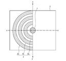
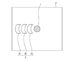
- FIG. 1 and 2 are diagrams for explaining a schematic configuration of an ultrasonic transmission / reception device 100 according to Embodiment 1 of the present invention.
- FIG. 1 is a plan view seen from an attachment side of the ultrasonic sensor 1
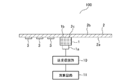
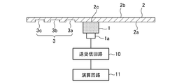
- FIG. 2 is a cross-sectional view taken along line AA ′ of FIG.
- the ultrasonic transmission / reception apparatus 100 includes an ultrasonic sensor 1, a wall member 2, a rigidity changing unit 3 that changes the rigidity of the wall member 2, and transmission / reception.
- a circuit 10 and an arithmetic circuit 11 are provided.
- the ultrasonic sensor 1 has a radiation surface 1b.
- the ultrasonic sensor 1 is attached so that the radiation surface 1b of the ultrasonic sensor 1 contacts a mounting portion 2c set on the mounting surface 2a that is one surface of the wall member 2.
- the ultrasonic sensor 1 is connected to the transmission / reception circuit 10 through an input / output terminal 1a.
- the transmission / reception circuit 10 includes a transmission circuit (not shown) and a reception circuit (not shown), and the transmission circuit and the reception circuit are electrically connected.
- An arithmetic circuit 11 is electrically connected to the transmission / reception circuit 10.
- the arithmetic circuit 11 calculates a relative distance to a target object such as an obstacle, a transmitted sound speed, or the like using an existing generally known technique. Regarding the relative distance, specifically, the arithmetic circuit 11 calculates the relative distance based on the time from when the ultrasonic wave is transmitted until the ultrasonic wave is reflected by the obstacle and when the reflected ultrasonic wave is received again and a predetermined sound velocity. Calculate the distance.
- the transmission / reception circuit 10 and the arithmetic circuit 11 are each connected to a power source (not shown).
- the rigidity changing part 3 is a part for changing the rigidity of the wall member 2, and is provided on the attachment surface 2a of the wall member 2 and sandwiched in two directions extending from the attachment part 2c to which the ultrasonic sensor 1 is attached. Provided in the area.
- two directions extending from an attachment portion 2 c to which the ultrasonic sensor 1 is attached are indicated by X and X ′.
- the angle between the straight line in the X direction and the straight line in the X ′ direction is 180 °, but the starting point is the mounting portion 2 c to which the ultrasonic sensor 1 is mounted.
- the angle formed by straight lines extending in two directions is not limited to 180 °.
- the rigidity changing portion 3 is formed by convex members 3 a, 3 b, 3 c having a predetermined shape, and the shape of the rigidity changing portion 3 is shown here. Is assumed to be semicircular. Further, at least one or more of the convex members 3a, 3b, 3c are provided at arbitrary intervals.
- the convex members 3a, 3c, One 3b and 3c may be provided, two may be provided, or four or more may be provided.
- the convex members 3a, 3b, 3c forming the rigidity changing portion 3 are provided.
- the width and height of the three convex members 3a, 3b, and 3c provided are the same.
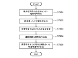
- FIG. 3 is a flowchart for explaining the operation of the ultrasonic transmitting / receiving apparatus 100 according to the first embodiment of the present invention.
- the transmission circuit of the transmission / reception circuit 10 applies an electrical signal to the ultrasonic sensor 1 (step ST301).
- the ultrasonic sensor 1 is excited, whereby the ultrasonic sensor 1 is placed on the side opposite to the mounting surface 2a of the wall member 2 via the wall member 2. Ultrasonic waves are transmitted to the space (step ST302).
- the ultrasonic wave transmitted by the ultrasonic sensor 1 in step ST302 is reflected by an obstacle or the like existing in the space opposite to the mounting surface 2a of the wall member 2, and again the surface 2b opposite to the mounting surface 2a of the wall member 2.
- the ultrasonic sensor 1 receives the reflected ultrasonic wave through the wall member 2 (step ST303).
- step ST303 when the ultrasonic sensor 1 receives the ultrasonic wave, the ultrasonic sensor 1 performs a process based on the received ultrasonic wave, converts the received ultrasonic wave into an electric signal, and transmits the electric signal to the reception circuit of the transmission / reception circuit 10. .
- the reception circuit of the transmission / reception circuit 10 receives an electrical signal from the ultrasonic sensor 1 and transmits the received electrical signal to the arithmetic circuit 11 (step ST304).
- the arithmetic circuit 11 receives the electrical signal transmitted in step ST304, and calculates the relative distance to the obstacle or the transmitted sound speed based on the received electrical signal (step ST305).
- the arithmetic circuit 11 may calculate the relative distance or the like in the transmission / reception circuit 10 or the transmission sound speed by using an existing and generally known technique, and thus detailed description thereof is omitted.
- step ST302 When an electrical signal is applied to the ultrasonic sensor 1, the radiation surface 1b vibrates.
- the ultrasonic sensor 1 is attached so that the radiation surface 1b of the ultrasonic sensor 1 is in contact with an attachment portion 2c set on the attachment surface 2a of the wall member 2. For this reason, the vibration of the radiation surface 1b propagates to the wall member 2, and the wall member 2 vibrates. Due to this vibration, ultrasonic waves are transmitted from the surface 2b of the wall member 2 opposite to the mounting surface 2a.
- the vibration displacement of the mounting portion 2 c in contact with the radiation surface 1 b becomes large and the vibration displacement of the mounting portion 2 c in contact with the radiation surface 1 b becomes dominant, but the radiation surface 1 b is in contact.
- the wall member 2 other than the mounting portion 2c to be vibrated also vibrates.
- the rigidity change formed by the convex members 3a, 3b, and 3c on the mounting surface 2a of the wall member 2 in a region sandwiched in two directions extending from the mounting portion 2c. Part 3 is provided. That is, the mounting surface 2a of the wall member 2 has an asymmetric structure around the mounting portion 2c to which the ultrasonic sensor 1 is mounted. In the region where the rigidity changing portion 3 in the wall member 2 is provided, the ultrasonic sensor The vibration energy due to 1 is difficult to propagate. For this reason, the wall member 2 on the side where the rigidity changing portion 3 is provided is less likely to vibrate.
- the vibration energy from the ultrasonic sensor 1 propagates, and thus the wall member 2 vibrates more than the region in which the rigidity changing portion 3 is provided. Therefore, the vibration distribution in the wall member 2 is asymmetric.
- the ultrasonic wave is transmitted predominantly from the mounting portion 2c with which the radiation surface 1b of the ultrasonic sensor 1 in the wall member 2 contacts, but the rigidity changing portion 3 in the wall member 2 is transmitted.
- the region not provided with vibrations also vibrates and generates ultrasonic waves. For this reason, the generated ultrasonic waves interfere with each other, and the ultrasonic waves are radiated in a direction inclined toward the region where the rigidity changing portion 3 is provided.
- FIG. 4 is a diagram for explaining the effect of the ultrasonic transmitting / receiving apparatus 100 according to the first embodiment.
- FIG. 4 shows the calculation result of the directivity obtained using the finite element method for the ultrasonic transmitting / receiving apparatus 100 according to the first embodiment. 4, as shown in FIGS. 1 and 2, a convex shape that forms the stiffness changing portion 3 on the left side of the mounting surface 2 a of the wall member 2 starting from the mounting portion 2 c to which the ultrasonic sensor 1 is mounted.
- the directivity calculation result regarding the ultrasonic transmitting / receiving apparatus 100 in which a plurality of members 3a, 3b, 3c are arranged is shown.
- the directivity calculation result of the ultrasonic transmission / reception apparatus 100 according to the first embodiment is indicated by a solid line as the first directivity calculation result (A).
- the directivity characteristic of the ultrasonic transmission / reception apparatus having a general configuration including the ultrasonic sensor 1, the transmission / reception circuit 10, and the arithmetic circuit 11 is provided without providing the rigidity changing unit 3 as described with reference to FIGS.
- the calculation result is also indicated by a broken line as the second directivity characteristic calculation result (B).
- the horizontal axis indicates the front direction of the ultrasonic transmission / reception apparatus 100, that is, the direction perpendicular to the wall member 2 through the approximate center of the attachment portion 2 c, and is approximately 0 ° of the attachment portion 2 c in FIG. 2.
- the inclination to the left side with respect to the center is represented by a negative value, and the inclination to the right side is represented by a positive value.
- the vertical axis represents the radiation sound pressure level.
- the radiated sound pressure level has a maximum value in the vicinity of the 0 ° direction as shown as the second directivity characteristic calculation result (B).
- the radiated sound pressure level shows the maximum value in the vicinity of the ⁇ 5 ° direction
- the angle at which the radiated sound pressure level shows the maximum value is shifted to the minus side. Therefore, it can be seen that in the ultrasonic transmitting / receiving apparatus 100 according to the first embodiment, the ultrasonic waves are radiated in a direction inclined from the front direction. Further, the sound pressure level in the direction of ⁇ 80 ° in the second directivity characteristic calculation result (B) is also reduced in the first directivity characteristic calculation result (A) by the ultrasonic transmission / reception device 100 provided with the stiffness changing unit 3. It can be seen that the effect of suppressing the side lobes can be obtained by providing the rigidity changing portion 3.
- the ultrasonic transmission / reception device 100 is used in an obstacle detection system that detects an obstacle around the vehicle, and the wall member 2 is assumed to be a bumper such as an automobile, for example. is doing.
- the wall member 2 is a bumper
- the mounting surface 2a that is one surface of the wall member 2 is an inner surface of the bumper.
- the direction in which the ultrasonic waves are radiated at an inclined angle is set to a direction opposite to the road surface, and the ultrasonic transmission / reception device 100 is used.
- the ultrasonic waves radiated in the road surface direction are reduced, and reflected waves from the road surface are reduced.
- the side lobe component is also reduced, the directivity can be increased, and erroneous detection due to a reflected wave from the road surface can be reduced.
- FIG. 5 shows that the ultrasonic transmission / reception device 100 according to the first embodiment is applied to an obstacle detection system, and is applied to the wall member 2, that is, the vehicle bumper so that the ultrasonic wave radiated in the road surface direction is reduced. It is a figure explaining an example which attached.
- FIG. 5 is a plan view seen from the attachment side of the ultrasonic sensor 1. As shown in FIG. 5, the convex members 3a, 3b, 3c forming the rigidity changing portion 3 are arranged in a region sandwiched in two directions extending from the mounting portion 2c on the mounting surface 2a of the wall member 2. As described above, the ultrasonic transmission / reception apparatus 100 is set.
- the radiation direction of the ultrasonic wave transmitted from the ultrasonic sensor 1 is inclined in the direction opposite to the road surface, the ultrasonic wave radiated in the road surface direction is reduced, and the reflected wave from the road surface is reduced. Is reduced. And thereby, the false detection by the reflected wave from a road surface can be reduced.
- the ultrasonic transmission / reception device 100 is an obstacle detection device that detects an obstacle existing around the vehicle, and the ultrasonic sensor 1 is attached to bumpers before and after the vehicle.
- the wall member 2 corresponds to a bumper of a vehicle, the wall member 2 is a rigid resin molded product such as polypropylene or urethane.
- the wall member 2 is not particularly limited, and Any material or shape suitable for the propagation of sound waves may be used.
- a structure in which the radiation surface 1b of the ultrasonic sensor 1 and the wall member 2 are bonded and fixed may be used.
- an acoustic matching layer having an acoustic impedance intermediate between the acoustic impedance of the ultrasonic sensor 1 and the acoustic impedance of the wall member 2 may be provided between the ultrasonic sensor 1 and the wall member 2.
- the radiation surface 1b of the ultrasonic sensor 1 may be attached to the attachment portion 2c via an acoustic matching layer having an acoustic impedance intermediate between the acoustic impedance of the ultrasonic sensor 1 and the acoustic impedance of the wall member 2. Good.
- the radiation surface 1b of the ultrasonic sensor 1 By allowing the radiation surface 1b of the ultrasonic sensor 1 to be attached to the attachment portion 2c via the acoustic matching layer, reflection at the boundary between the ultrasonic sensor 1 and the wall member 2 is reduced.
- the ultrasonic wave propagating from the wall member 2 to the wall member 2 increases, and the sound pressure of the ultrasonic wave radiated from the wall member 2 is improved.
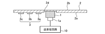
- Other fixing methods may be used as long as the ultrasonic sensor 1 is fixed to the wall member 2.
- the attachment portion 2c is formed as a digging portion 2d on the attachment surface 2a that is one surface of the wall member 2, and the radiation surface 1b of the ultrasonic sensor 1 is formed as the digging portion 2d. It may be attached to 2c. Since the radiation surface 1b of the ultrasonic sensor 1 is attached to the attachment portion 2c formed as the digging portion 2d, the thickness of the wall member 2 of the attachment portion 2c is reduced. Propagation distance of the ultrasonic wave becomes shorter.
- the material of the convex members 3a, 3b, 3c forming the rigidity changing portion 3 is not particularly limited, and the same material as the wall member 2 may be used, or a material different from the wall member 2 may be used. It is also possible to use a metal such as aluminum. As a material for the wall member 2, resin is generally used, but when resin and metal are compared, the density of metal is larger in the case of a convex member of the same size because the density of metal is higher. And the vibration of the wall member 2 can be further suppressed.
- the convex members 3a, 3b, 3c forming the rigidity changing portion 3 may be integrally formed, or convex members 3 a, 3 b, 3 c forming the rigidity changing portion 3 created separately from the wall member 2 may be attached to the wall member 2.
- the shape of the convex members 3 a, 3 b, 3 c forming the rigidity changing portion 3 has been described as a semi-annular shape, but not limited to this, the rigidity changing portion
- the convex members 3 a, 3 b, 3 c forming the shape 3 may be any shape that can change the rigidity of the wall member 2.
- the shape of the convex members 3a, 3b, 3c forming the rigidity changing portion 3 may be an arc as shown in FIG.
- the shape of the convex members 3a, 3b, 3c forming the rigidity changing portion 3 may be rectangular as shown in FIG.
- the shape and arrangement of the stiffness changing portion 3 are determined according to the vibration distribution.
- the shape of the convex members 3a, 3b, 3c forming the rigidity changing portion 3 is a rectangle, and the rectangles are all the same shape, but not limited to this, as shown in FIG. 9A
- the long sides of the convex members 3a, 3b, and 3c forming the rigidity changing portion 3 may be gradually shortened in the direction away from the ultrasonic sensor 1, or FIG. 9B.
- the rectangular long sides of the convex members 3 a, 3 b, 3 c forming the rigidity changing portion 3 may be gradually elongated in the direction away from the ultrasonic sensor 1. .
- the convex members 3a, 3b, 3c forming the rigidity changing portion 3 are formed in a semicircular shape, and as shown in FIG. 10A, the convex member 3a forming the rigidity changing portion 3 is formed. , 3b, 3c may have a shape in which the arc length gradually decreases in the direction away from the ultrasonic sensor 1, or as shown in FIG. 10B, convex members 3a, 3b forming the rigidity changing portion 3 , 3c may have a shape in which the arc length gradually increases in a direction away from the ultrasonic sensor 1.
- the stiffness changing portion 3 is arranged in a region sandwiched in two directions extending from the mounting portion 2c on the mounting surface 2a of the wall member 2, the stiffness changing portion 3 is ultrasonically You may make it provide so that a row
- rectangular convex members 3 a, 3 b, 3 c forming the rigidity changing portion 3 are arranged along a plurality of directions on the mounting surface 2 a of the wall member 2 with the mounting portion 2 c as a center. They may be arranged in rows.
- the rigidity change part 3 was demonstrated as what is formed with a convex-shaped member, as shown in FIG. 12, a groove
- the shape of the groove, that is, the concave portion is the same as the case where the rigidity changing portion 3 is formed by a convex member, as described with reference to FIGS. It may be a simple shape or an arrangement.
- the rigidity changing portion 3 may be formed by filling a concave groove provided on the mounting surface 2 a of the wall member 2 with a material different from that of the wall member 2.
- the shape of the groove is the same as that described with reference to FIGS. 7 to 11, such as a semi-annular shape, a rectangular shape, or the like, as in the case where the rigidity changing portion 3 is formed by a convex member. It is good also as arrangement.
- the rigidity changing portion 3 may be formed by combining materials and shapes as described above.
- the rigidity changing portion 3 is configured by providing a convex member made of the same material as the wall member 2, a convex member made of a material different from the wall member 2, and a groove in the wall member 2.
- the concave portion provided in the concave portion and the wall member 2 may be formed by combining at least two or more of those formed by filling a material different from that of the wall member 2.
- the rigidity change part 3 can also be formed by a plurality of convex members or concave parts having two or more different shapes such as a semicircular ring shape and an arc shape.
- the plurality of convex members forming the rigidity changing portion 3 or the width and height of the concave portions are described as being the same.
- the present invention is not limited to this, and the width and height are changed.
- a plurality of convex members or concave portions may be arranged on the mounting surface 2 a of the wall member 2.
- the rigidity changing portion 3 may be arranged at a position that becomes a peak or valley of the vibration displacement distribution in the vibration displacement distribution in the wall member 2.
- the direction in which the ultrasonic waves are radiated can be adjusted by changing the rigidity of the wall member 2 by the rigidity changing portion 3.
- Embodiment 2 FIG.
- the ultrasonic sensor 1 is provided on the mounting surface 2a of the planar wall member 2.
- the ultrasonic sensor 1 is attached to a through hole provided in the wall member 2 will be described.
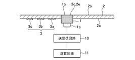
- FIG. 14 and 15 are diagrams for explaining a schematic configuration of the ultrasonic transmission / reception device 100 according to Embodiment 2 of the present invention.
- FIG. 14 is a plan view seen from the attachment side of the ultrasonic sensor 1.
- FIG. 15 is a cross-sectional view taken along the line AA ′ of FIG.
- the configuration of the ultrasonic transmitting / receiving apparatus 100 according to the second embodiment of the present invention is the same as that described with reference to FIGS. 1 and 2 in the first embodiment. And redundant description is omitted.
- the ultrasonic transmitting / receiving apparatus 100 according to the second embodiment of the present invention differs from the ultrasonic transmitting / receiving apparatus 100 according to the first embodiment only in the structure in which the ultrasonic sensor 1 is attached to the wall member 2. Only points different from the first embodiment will be described below with reference to FIGS.
- a through hole 2 e is formed in the attachment portion 2 c of the wall member 2 to which the ultrasonic sensor 1 is attached.
- the ultrasonic sensor 1 is exposed to the through hole 2e so that the radiation surface 1b of the ultrasonic sensor 1 is exposed as a surface substantially the same as the surface 2b opposite to the mounting surface 2a of the wall member 2.
- the radiation surface 1b of the ultrasonic sensor 1 and the surface 2b opposite to the mounting surface 2a of the wall member 2 are substantially the same surface.
- the surface 2b opposite to the mounting surface 2a form a flat plane at the same height when viewed from the cross section, and the radiation surface 1b of the ultrasonic sensor 1 when viewed from the cross section It includes that the difference in height between the surface 2b opposite to the mounting surface 2a of the wall member 2 is small enough not to impair the appearance.
- the attachment surface 2a of the wall member 2 is provided with the rigidity changing portion 3 in a region sandwiched in two directions extending from the attachment portion 2c to which the ultrasonic sensor 1 is attached.
- the rigidity changing portion 3 is provided.
- the operation will be described.
- the basic operation of the ultrasonic transmitting / receiving apparatus 100 according to the second embodiment of the present invention is the same as the operation described in the first embodiment using the flowchart of FIG.
- the ultrasonic transmission / reception apparatus 100 according to the second embodiment of the present invention and the ultrasonic transmission / reception apparatus 100 according to the first embodiment differ only in how the ultrasonic waves are transmitted. To do.
- the radiation surface 1b of the ultrasonic sensor 1 vibrates.
- the ultrasonic sensor 1 is attached to the through hole 2e provided in the wall member 2, and the radiation surface 1b is the attachment surface of the wall member 2. Since it is exposed on the opposite side to 2a, the ultrasonic wave generated by the vibration of the radiation surface 1b is directly transmitted from the radiation surface 1b. Moreover, since the side surface of the ultrasonic sensor 1 vibrates with the vibration of the radiation surface 1b, the vibration propagates to the wall member 2, and the wall member 2 also vibrates.
- the rigidity changing portion 3 formed by the convex members 3a, 3b, 3c is provided on the mounting surface 2a of the wall member 2 in a region sandwiched in two directions extending from the mounting portion 2c. . That is, the mounting surface 2a of the wall member 2 has an asymmetric structure around the mounting portion 2c to which the ultrasonic sensor 1 is mounted. In the region where the rigidity changing portion 3 in the wall member 2 is provided, the ultrasonic sensor The vibration energy due to 1 is difficult to propagate. For this reason, the wall member 2 on the side where the rigidity changing portion 3 is provided is less likely to vibrate.
- the vibration energy from the ultrasonic sensor 1 propagates, and thus the wall member 2 vibrates more than the region in which the rigidity changing portion 3 is provided. Therefore, the vibration distribution in the wall member 2 is asymmetric.
- the ultrasonic wave is dominantly transmitted directly from the radiation surface 1b of the ultrasonic sensor 1, but the region of the wall member 2 where the rigidity changing portion 3 is not provided also vibrates. Ultrasonic waves are generated. For this reason, the generated ultrasonic waves interfere with each other, and the ultrasonic waves are radiated in a direction inclined toward the region where the rigidity changing portion 3 is provided.
- the direction in which the ultrasonic waves are radiated at an inclined angle is set to a direction opposite to the road surface.
- the sound wave transmitting / receiving device 100 By attaching the sound wave transmitting / receiving device 100 to the vehicle, ultrasonic waves radiated in the road surface direction are reduced, and reflected waves from the road surface are reduced.
- the side lobe component is also reduced, the directivity can be increased, and erroneous detection due to a reflected wave from the road surface can be reduced.
- the convex members 3a, 3b, 3c forming the rigidity changing portion 3 are arranged in a region sandwiched in two directions extending from the mounting portion 2c on the mounting surface 2a of the wall member 2.
- the ultrasonic transmission / reception apparatus 100 is set (see FIG. 5).
- the radiation direction of the ultrasonic wave transmitted from the ultrasonic sensor 1 is inclined in the direction opposite to the road surface, the ultrasonic wave radiated in the road surface direction is reduced, and the reflected wave from the road surface is reduced. Is reduced. And thereby, the false detection by the reflected wave from a road surface can be reduced.
- the convex members 3a, 3b, 3c or the concave portions forming the rigidity changing portion 3 of the second embodiment may be semicircular, arcuate, rectangular as in the first embodiment.
- the various shapes described in Embodiment Mode 1 can be used.
- the convex members 3a, 3b, 3c forming the rigidity changing portion 3 of the second embodiment or the arrangement of the concave portions are also provided, for example, as shown in FIG.
- the convex members 3a, 3b, 3c to be formed, or the concave portions can be arranged in rows along a plurality of directions on the mounting surface 2a of the wall member 2 with the mounting portion 2c as the center. .
- the direction in which the ultrasonic waves are emitted can be adjusted by changing the rigidity of the wall member 2 by the rigidity changing unit 3.
- the radiation surface 1b of the ultrasonic sensor 1 is exposed as a surface substantially the same as the surface 2b opposite to the mounting surface 2a of the wall member 2.
- the design is inferior.
- the ultrasonic wave transmitting / receiving apparatus 100 according to the second embodiment can adjust the direction in which the ultrasonic waves are radiated as described above, the direction in which the ultrasonic waves are radiated can be thereby inclined, and side lobes are suppressed. can do. As a result, false detection can be reduced.
- the ultrasonic transmission / reception device 100 is used in an obstacle detection system that detects an obstacle or the like around the vehicle, and the wall member 2 is, for example, an automobile.
- the use of the ultrasonic transmission / reception apparatus 100 of the present invention is not limited to a bumper of an automobile.
- the ultrasonic sensor 1 can be fixed to the outside of the lid of the liquid tank, and the ultrasonic transmission / reception device 100 can be used as a liquid level detection device for the liquid in the liquid tank.
- the ultrasonic sensor 1 can be fixed to the outer wall of the building or the inner side surface of the indoor wall, and the ultrasonic transmission / reception device 100 can be used as an intruder detection device.
- the radiation surface 1b of the ultrasonic sensor 1 is attached to the attachment surface 2a of the wall member 2 as shown in FIGS.
- the method of attaching the ultrasonic sensor 1 to the wall member 2 is as follows. An attachment portion 2c of the ultrasonic sensor 1 is set on the attachment surface 2a of the wall member 2 to which the radiation surface 1b of the ultrasonic sensor 1 is attached, and the region of the attachment surface 2a sandwiched in two directions extending from the attachment portion 2c as a starting point. Then, the rigidity changing portion 3 composed of the convex members 3a, 3b, 3c is formed. And the ultrasonic sensor 1 is attached to the attaching part 2c. In addition, the order of the process of setting the attaching part 2c and the process of forming the rigidity change part 3 is not ask
- the ultrasonic transmission / reception device 100 is configured as shown in FIGS. 1, 2, 14, and 15.
- the ultrasonic transmission / reception device 100 includes the ultrasonic sensor 1, By providing the rigidity changing portion 3, the above-described effects can be obtained.
- the invention of the present application can be freely combined with each embodiment, modified with any component in each embodiment, or omitted with any component in each embodiment. .
- the ultrasonic transmission / reception apparatus is configured such that the direction in which the ultrasonic waves are radiated can be adjusted by changing the rigidity of the wall member by the rigidity changing unit. It can be applied to a transmission / reception device.
Landscapes
- Engineering & Computer Science (AREA)
- Physics & Mathematics (AREA)
- Radar, Positioning & Navigation (AREA)
- Remote Sensing (AREA)
- Mechanical Engineering (AREA)
- Acoustics & Sound (AREA)
- Computer Networks & Wireless Communication (AREA)
- General Physics & Mathematics (AREA)
- Signal Processing (AREA)
- Transducers For Ultrasonic Waves (AREA)
- Measurement Of Velocity Or Position Using Acoustic Or Ultrasonic Waves (AREA)
Abstract
La présente invention comprend : un capteur à ultrasons (1) qui a une surface de rayonnement (1b) ; et un élément de paroi (2) qui a une surface de fixation (2a) ayant une section de fixation (2c) sur laquelle la surface de rayonnement (1b) du capteur à ultrasons est montée, et des parties de changement de rigidité (3) disposées sur la surface de fixation (2a) et dans une zone entre deux directions s'étendant depuis la section de fixation (2c).
Priority Applications (2)
| Application Number | Priority Date | Filing Date | Title |
|---|---|---|---|
| PCT/JP2016/054731 WO2017141402A1 (fr) | 2016-02-18 | 2016-02-18 | Appareil de transmission/réception d'ultrasons, élément de paroi, et procédé de fixation de capteur à ultrasons à un élément de paroi |
| JP2016552541A JPWO2017141402A1 (ja) | 2016-02-18 | 2016-02-18 | 超音波送受信装置、壁部材、および、壁部材への超音波センサの取付方法 |
Applications Claiming Priority (1)
| Application Number | Priority Date | Filing Date | Title |
|---|---|---|---|
| PCT/JP2016/054731 WO2017141402A1 (fr) | 2016-02-18 | 2016-02-18 | Appareil de transmission/réception d'ultrasons, élément de paroi, et procédé de fixation de capteur à ultrasons à un élément de paroi |
Publications (1)
| Publication Number | Publication Date |
|---|---|
| WO2017141402A1 true WO2017141402A1 (fr) | 2017-08-24 |
Family
ID=59625633
Family Applications (1)
| Application Number | Title | Priority Date | Filing Date |
|---|---|---|---|
| PCT/JP2016/054731 Ceased WO2017141402A1 (fr) | 2016-02-18 | 2016-02-18 | Appareil de transmission/réception d'ultrasons, élément de paroi, et procédé de fixation de capteur à ultrasons à un élément de paroi |
Country Status (2)
| Country | Link |
|---|---|
| JP (1) | JPWO2017141402A1 (fr) |
| WO (1) | WO2017141402A1 (fr) |
Cited By (1)
| Publication number | Priority date | Publication date | Assignee | Title |
|---|---|---|---|---|
| JP2021183951A (ja) * | 2020-05-22 | 2021-12-02 | 株式会社Soken | 超音波センサ取付構造 |
Citations (8)
| Publication number | Priority date | Publication date | Assignee | Title |
|---|---|---|---|---|
| JPH1070784A (ja) * | 1996-04-16 | 1998-03-10 | Robert Bosch Gmbh | 音響信号を送受信するためのセンサ |
| JP2001016694A (ja) * | 1999-06-25 | 2001-01-19 | Denso Corp | 超音波センサ |
| JP2005072771A (ja) * | 2003-08-21 | 2005-03-17 | Nippon Soken Inc | 超音波センサ |
| JP2007147319A (ja) * | 2005-11-24 | 2007-06-14 | Nippon Soken Inc | 障害物検知装置 |
| JP2008096113A (ja) * | 2006-10-05 | 2008-04-24 | Nippon Soken Inc | 障害物検出装置 |
| JP2010014496A (ja) * | 2008-07-02 | 2010-01-21 | Nippon Soken Inc | 超音波センサの取付け構造 |
| WO2011048649A1 (fr) * | 2009-10-19 | 2011-04-28 | 三菱電機株式会社 | Capteur ultrasonique aérien |
| WO2011067835A1 (fr) * | 2009-12-02 | 2011-06-09 | 三菱電機株式会社 | Capteur ultrasonique aérien |
-
2016
- 2016-02-18 JP JP2016552541A patent/JPWO2017141402A1/ja active Pending
- 2016-02-18 WO PCT/JP2016/054731 patent/WO2017141402A1/fr not_active Ceased
Patent Citations (8)
| Publication number | Priority date | Publication date | Assignee | Title |
|---|---|---|---|---|
| JPH1070784A (ja) * | 1996-04-16 | 1998-03-10 | Robert Bosch Gmbh | 音響信号を送受信するためのセンサ |
| JP2001016694A (ja) * | 1999-06-25 | 2001-01-19 | Denso Corp | 超音波センサ |
| JP2005072771A (ja) * | 2003-08-21 | 2005-03-17 | Nippon Soken Inc | 超音波センサ |
| JP2007147319A (ja) * | 2005-11-24 | 2007-06-14 | Nippon Soken Inc | 障害物検知装置 |
| JP2008096113A (ja) * | 2006-10-05 | 2008-04-24 | Nippon Soken Inc | 障害物検出装置 |
| JP2010014496A (ja) * | 2008-07-02 | 2010-01-21 | Nippon Soken Inc | 超音波センサの取付け構造 |
| WO2011048649A1 (fr) * | 2009-10-19 | 2011-04-28 | 三菱電機株式会社 | Capteur ultrasonique aérien |
| WO2011067835A1 (fr) * | 2009-12-02 | 2011-06-09 | 三菱電機株式会社 | Capteur ultrasonique aérien |
Cited By (2)
| Publication number | Priority date | Publication date | Assignee | Title |
|---|---|---|---|---|
| JP2021183951A (ja) * | 2020-05-22 | 2021-12-02 | 株式会社Soken | 超音波センサ取付構造 |
| JP7413921B2 (ja) | 2020-05-22 | 2024-01-16 | 株式会社Soken | 超音波センサ取付構造 |
Also Published As
| Publication number | Publication date |
|---|---|
| JPWO2017141402A1 (ja) | 2018-02-22 |
Similar Documents
| Publication | Publication Date | Title |
|---|---|---|
| EP1962552B1 (fr) | Transducteur ultrasonique | |
| JP4917401B2 (ja) | 障害物検出装置 | |
| US8943893B2 (en) | Ultrasonic sensor | |
| EP2858378B1 (fr) | Transducteur d'échosondeur ultrasonore et débitmètre ultrasonore équipé le comprenant | |
| CN102665940B (zh) | 超声波振动装置 | |
| KR101550953B1 (ko) | 초음파 센서 | |
| US7692367B2 (en) | Ultrasonic transducer | |
| JP2007147319A (ja) | 障害物検知装置 | |
| WO2023079789A1 (fr) | Transducteur ultrasonore | |
| JP4618165B2 (ja) | 超音波センサ | |
| JP5950742B2 (ja) | 超音波送受波器 | |
| JP6611992B2 (ja) | 超音波センサ装置及び障害物検知装置 | |
| JP2016139871A (ja) | 超音波トランスデューサ | |
| WO2017141402A1 (fr) | Appareil de transmission/réception d'ultrasons, élément de paroi, et procédé de fixation de capteur à ultrasons à un élément de paroi | |
| JP2010014496A (ja) | 超音波センサの取付け構造 | |
| JP4023061B2 (ja) | 超音波振動子 | |
| JP2009065380A (ja) | 超音波センサ | |
| JP2004097851A (ja) | 超音波振動装置 | |
| KR100808370B1 (ko) | 비대칭 지향각을 갖는 초음파센서 | |
| JP3367446B2 (ja) | 防滴型超音波振動子 | |
| JP5340432B2 (ja) | 超音波センサ | |
| JP2016208423A (ja) | 超音波トランスデューサ、およびそれを用いた車両用センサ | |
| JP7367322B2 (ja) | 対象物位置検出センサ | |
| JP4415945B2 (ja) | ホーン | |
| JP4768684B2 (ja) | 超音波センサ |
Legal Events
| Date | Code | Title | Description |
|---|---|---|---|
| ENP | Entry into the national phase |
Ref document number: 2016552541 Country of ref document: JP Kind code of ref document: A |
|
| 121 | Ep: the epo has been informed by wipo that ep was designated in this application |
Ref document number: 16890543 Country of ref document: EP Kind code of ref document: A1 |
|
| NENP | Non-entry into the national phase |
Ref country code: DE |
|
| 122 | Ep: pct application non-entry in european phase |
Ref document number: 16890543 Country of ref document: EP Kind code of ref document: A1 |