WO2017141402A1 - 超音波送受信装置、壁部材、および、壁部材への超音波センサの取付方法 - Google Patents
超音波送受信装置、壁部材、および、壁部材への超音波センサの取付方法 Download PDFInfo
- Publication number
- WO2017141402A1 WO2017141402A1 PCT/JP2016/054731 JP2016054731W WO2017141402A1 WO 2017141402 A1 WO2017141402 A1 WO 2017141402A1 JP 2016054731 W JP2016054731 W JP 2016054731W WO 2017141402 A1 WO2017141402 A1 WO 2017141402A1
- Authority
- WO
- WIPO (PCT)
- Prior art keywords
- wall member
- ultrasonic
- ultrasonic sensor
- attachment
- reception apparatus
- Prior art date
- Legal status (The legal status is an assumption and is not a legal conclusion. Google has not performed a legal analysis and makes no representation as to the accuracy of the status listed.)
- Ceased
Links
Images






Classifications
-
- B—PERFORMING OPERATIONS; TRANSPORTING
- B60—VEHICLES IN GENERAL
- B60R—VEHICLES, VEHICLE FITTINGS, OR VEHICLE PARTS, NOT OTHERWISE PROVIDED FOR
- B60R19/00—Wheel guards; Radiator guards, e.g. grilles; Obstruction removers; Fittings damping bouncing force in collisions
- B60R19/02—Bumpers, i.e. impact receiving or absorbing members for protecting vehicles or fending off blows from other vehicles or objects
- B60R19/48—Bumpers, i.e. impact receiving or absorbing members for protecting vehicles or fending off blows from other vehicles or objects combined with, or convertible into, other devices or objects, e.g. bumpers combined with road brushes, bumpers convertible into beds
-
- B—PERFORMING OPERATIONS; TRANSPORTING
- B60—VEHICLES IN GENERAL
- B60R—VEHICLES, VEHICLE FITTINGS, OR VEHICLE PARTS, NOT OTHERWISE PROVIDED FOR
- B60R21/00—Arrangements or fittings on vehicles for protecting or preventing injuries to occupants or pedestrians in case of accidents or other traffic risks
-
- G—PHYSICS
- G01—MEASURING; TESTING
- G01S—RADIO DIRECTION-FINDING; RADIO NAVIGATION; DETERMINING DISTANCE OR VELOCITY BY USE OF RADIO WAVES; LOCATING OR PRESENCE-DETECTING BY USE OF THE REFLECTION OR RERADIATION OF RADIO WAVES; ANALOGOUS ARRANGEMENTS USING OTHER WAVES
- G01S15/00—Systems using the reflection or reradiation of acoustic waves, e.g. sonar systems
- G01S15/88—Sonar systems specially adapted for specific applications
- G01S15/93—Sonar systems specially adapted for specific applications for anti-collision purposes
-
- G—PHYSICS
- G01—MEASURING; TESTING
- G01S—RADIO DIRECTION-FINDING; RADIO NAVIGATION; DETERMINING DISTANCE OR VELOCITY BY USE OF RADIO WAVES; LOCATING OR PRESENCE-DETECTING BY USE OF THE REFLECTION OR RERADIATION OF RADIO WAVES; ANALOGOUS ARRANGEMENTS USING OTHER WAVES
- G01S7/00—Details of systems according to groups G01S13/00, G01S15/00, G01S17/00
- G01S7/52—Details of systems according to groups G01S13/00, G01S15/00, G01S17/00 of systems according to group G01S15/00
- G01S7/521—Constructional features
-
- H—ELECTRICITY
- H04—ELECTRIC COMMUNICATION TECHNIQUE
- H04R—LOUDSPEAKERS, MICROPHONES, GRAMOPHONE PICK-UPS OR LIKE ACOUSTIC ELECTROMECHANICAL TRANSDUCERS; ELECTRIC HEARING AIDS; PUBLIC ADDRESS SYSTEMS
- H04R1/00—Details of transducers, loudspeakers or microphones
- H04R1/02—Casings; Cabinets ; Supports therefor; Mountings therein
Definitions
- the present invention relates to an ultrasonic transmission / reception device that transmits / receives ultrasonic waves, a wall member to which an ultrasonic sensor is attached, and a method of attaching the ultrasonic sensor to the wall member.
- An ultrasonic sensor using a piezoelectric element or the like is used for an obstacle detection system, for example.
- an ultrasonic wave is transmitted from the ultrasonic sensor to the air, and the transmitted ultrasonic wave is reflected by the obstacle or the like, propagates in the air, and is received by the ultrasonic sensor again. Obstacles are detected.
- a through hole for attaching the ultrasonic sensor is provided in a wall member such as a bumper of the vehicle. And an ultrasonic sensor is attached using this through-hole so that the radiation
- the radiation surface of the ultrasonic sensor is exposed from the outer surface of the bumper, which is not preferable in terms of design. Moreover, the process of providing a through-hole in a bumper is needed, and the operation
- Patent Document 1 discloses a configuration in which an ultrasonic sensor is attached to the inner surface of a wall member such as a bumper, thereby eliminating the step of providing a through hole in the bumper and transmitting and receiving ultrasonic waves without impairing the appearance. Is disclosed.
- the present invention has been made to solve the above-described problems, and provides an ultrasonic transmission / reception apparatus capable of adjusting the direction in which ultrasonic waves generated by the vibration of a wall member to which an ultrasonic sensor is attached are radiated. Objective.
- An ultrasonic transmission / reception apparatus includes an ultrasonic sensor having a radiation surface, an attachment surface having an attachment portion to which the emission surface of the ultrasonic sensor is attached, and provided on the attachment surface and extending from the attachment portion as a starting point. And a wall member having a stiffness changing portion provided in a region sandwiched in the direction.
- the ultrasonic transmission / reception apparatus of the present invention can adjust the direction in which ultrasonic waves are radiated by changing the rigidity of the wall member by the rigidity changing portion.
- FIG. 1 is a diagram illustrating a schematic configuration of an ultrasonic transmission / reception device according to Embodiment 1 of the present invention, and is a cross-sectional view taken along line A-A ′ of FIG. 1. It is a flowchart explaining the operation
- FIG. 1 it is a figure explaining an example of the fixing method to the wall member of an ultrasonic sensor.
- Embodiment 1 it is a figure explaining an example of the shape of the convex member which forms a rigidity change part.
- Embodiment 1 it is a figure explaining an example of the shape of the convex member which forms a rigidity change part.
- FIG. 9A the rectangular long side of the convex member which forms a rigidity change part is super
- FIG. 9B is a diagram for explaining a shape that gradually decreases in the direction away from the acoustic wave sensor
- FIG. 9B illustrates the direction in which the long side of the rectangular shape of the convex member forming the rigidity changing portion is away from the ultrasonic sensor. It is a figure explaining the shape which becomes long gradually.
- FIG. 9A the rectangular long side of the convex member which forms a rigidity change part
- FIG. 9B is a diagram for explaining a shape that gradually decreases in the direction away from the acoustic wave sensor
- FIG. 9B illustrates the direction in which the long side of the rectangular shape of the convex member forming the rigidity changing portion is away from the ultrasonic sensor. It is a figure explaining the shape which becomes long gradually.
- FIG. 9A the rectangular long side of the convex member which forms a rigidity change part is super
- FIG. 9B is
- FIG. 10A shows the circular arc length of the convex member which forms a rigidity change part as an ultrasonic sensor.
- FIG. 10B is a diagram illustrating a shape that gradually decreases in a direction away from the ultrasonic sensor.
- FIG. 10B is a diagram in which the arc length of the convex member that forms the stiffness changing portion gradually increases in the direction away from the ultrasonic sensor. It is a figure explaining a shape. The figure explaining an example which has arrange
- Embodiment 1 it is a figure explaining the example which provides a groove
- Embodiment 1 it is a figure explaining an example in which the rigidity change part fills the material different from a wall member in the concave groove
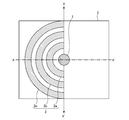
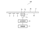
- FIG. 1 and 2 are diagrams for explaining a schematic configuration of an ultrasonic transmission / reception device 100 according to Embodiment 1 of the present invention.
- FIG. 1 is a plan view seen from an attachment side of the ultrasonic sensor 1
- FIG. 2 is a cross-sectional view taken along line AA ′ of FIG.
- the ultrasonic transmission / reception apparatus 100 includes an ultrasonic sensor 1, a wall member 2, a rigidity changing unit 3 that changes the rigidity of the wall member 2, and transmission / reception.
- a circuit 10 and an arithmetic circuit 11 are provided.
- the ultrasonic sensor 1 has a radiation surface 1b.
- the ultrasonic sensor 1 is attached so that the radiation surface 1b of the ultrasonic sensor 1 contacts a mounting portion 2c set on the mounting surface 2a that is one surface of the wall member 2.
- the ultrasonic sensor 1 is connected to the transmission / reception circuit 10 through an input / output terminal 1a.
- the transmission / reception circuit 10 includes a transmission circuit (not shown) and a reception circuit (not shown), and the transmission circuit and the reception circuit are electrically connected.
- An arithmetic circuit 11 is electrically connected to the transmission / reception circuit 10.
- the arithmetic circuit 11 calculates a relative distance to a target object such as an obstacle, a transmitted sound speed, or the like using an existing generally known technique. Regarding the relative distance, specifically, the arithmetic circuit 11 calculates the relative distance based on the time from when the ultrasonic wave is transmitted until the ultrasonic wave is reflected by the obstacle and when the reflected ultrasonic wave is received again and a predetermined sound velocity. Calculate the distance.
- the transmission / reception circuit 10 and the arithmetic circuit 11 are each connected to a power source (not shown).
- the rigidity changing part 3 is a part for changing the rigidity of the wall member 2, and is provided on the attachment surface 2a of the wall member 2 and sandwiched in two directions extending from the attachment part 2c to which the ultrasonic sensor 1 is attached. Provided in the area.
- two directions extending from an attachment portion 2 c to which the ultrasonic sensor 1 is attached are indicated by X and X ′.
- the angle between the straight line in the X direction and the straight line in the X ′ direction is 180 °, but the starting point is the mounting portion 2 c to which the ultrasonic sensor 1 is mounted.
- the angle formed by straight lines extending in two directions is not limited to 180 °.
- the rigidity changing portion 3 is formed by convex members 3 a, 3 b, 3 c having a predetermined shape, and the shape of the rigidity changing portion 3 is shown here. Is assumed to be semicircular. Further, at least one or more of the convex members 3a, 3b, 3c are provided at arbitrary intervals.
- the convex members 3a, 3c, One 3b and 3c may be provided, two may be provided, or four or more may be provided.
- the convex members 3a, 3b, 3c forming the rigidity changing portion 3 are provided.
- the width and height of the three convex members 3a, 3b, and 3c provided are the same.
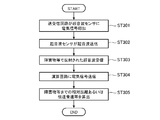
- FIG. 3 is a flowchart for explaining the operation of the ultrasonic transmitting / receiving apparatus 100 according to the first embodiment of the present invention.
- the transmission circuit of the transmission / reception circuit 10 applies an electrical signal to the ultrasonic sensor 1 (step ST301).
- the ultrasonic sensor 1 is excited, whereby the ultrasonic sensor 1 is placed on the side opposite to the mounting surface 2a of the wall member 2 via the wall member 2. Ultrasonic waves are transmitted to the space (step ST302).
- the ultrasonic wave transmitted by the ultrasonic sensor 1 in step ST302 is reflected by an obstacle or the like existing in the space opposite to the mounting surface 2a of the wall member 2, and again the surface 2b opposite to the mounting surface 2a of the wall member 2.
- the ultrasonic sensor 1 receives the reflected ultrasonic wave through the wall member 2 (step ST303).
- step ST303 when the ultrasonic sensor 1 receives the ultrasonic wave, the ultrasonic sensor 1 performs a process based on the received ultrasonic wave, converts the received ultrasonic wave into an electric signal, and transmits the electric signal to the reception circuit of the transmission / reception circuit 10. .
- the reception circuit of the transmission / reception circuit 10 receives an electrical signal from the ultrasonic sensor 1 and transmits the received electrical signal to the arithmetic circuit 11 (step ST304).
- the arithmetic circuit 11 receives the electrical signal transmitted in step ST304, and calculates the relative distance to the obstacle or the transmitted sound speed based on the received electrical signal (step ST305).
- the arithmetic circuit 11 may calculate the relative distance or the like in the transmission / reception circuit 10 or the transmission sound speed by using an existing and generally known technique, and thus detailed description thereof is omitted.
- step ST302 When an electrical signal is applied to the ultrasonic sensor 1, the radiation surface 1b vibrates.
- the ultrasonic sensor 1 is attached so that the radiation surface 1b of the ultrasonic sensor 1 is in contact with an attachment portion 2c set on the attachment surface 2a of the wall member 2. For this reason, the vibration of the radiation surface 1b propagates to the wall member 2, and the wall member 2 vibrates. Due to this vibration, ultrasonic waves are transmitted from the surface 2b of the wall member 2 opposite to the mounting surface 2a.
- the vibration displacement of the mounting portion 2 c in contact with the radiation surface 1 b becomes large and the vibration displacement of the mounting portion 2 c in contact with the radiation surface 1 b becomes dominant, but the radiation surface 1 b is in contact.
- the wall member 2 other than the mounting portion 2c to be vibrated also vibrates.
- the rigidity change formed by the convex members 3a, 3b, and 3c on the mounting surface 2a of the wall member 2 in a region sandwiched in two directions extending from the mounting portion 2c. Part 3 is provided. That is, the mounting surface 2a of the wall member 2 has an asymmetric structure around the mounting portion 2c to which the ultrasonic sensor 1 is mounted. In the region where the rigidity changing portion 3 in the wall member 2 is provided, the ultrasonic sensor The vibration energy due to 1 is difficult to propagate. For this reason, the wall member 2 on the side where the rigidity changing portion 3 is provided is less likely to vibrate.
- the vibration energy from the ultrasonic sensor 1 propagates, and thus the wall member 2 vibrates more than the region in which the rigidity changing portion 3 is provided. Therefore, the vibration distribution in the wall member 2 is asymmetric.
- the ultrasonic wave is transmitted predominantly from the mounting portion 2c with which the radiation surface 1b of the ultrasonic sensor 1 in the wall member 2 contacts, but the rigidity changing portion 3 in the wall member 2 is transmitted.
- the region not provided with vibrations also vibrates and generates ultrasonic waves. For this reason, the generated ultrasonic waves interfere with each other, and the ultrasonic waves are radiated in a direction inclined toward the region where the rigidity changing portion 3 is provided.
- FIG. 4 is a diagram for explaining the effect of the ultrasonic transmitting / receiving apparatus 100 according to the first embodiment.
- FIG. 4 shows the calculation result of the directivity obtained using the finite element method for the ultrasonic transmitting / receiving apparatus 100 according to the first embodiment. 4, as shown in FIGS. 1 and 2, a convex shape that forms the stiffness changing portion 3 on the left side of the mounting surface 2 a of the wall member 2 starting from the mounting portion 2 c to which the ultrasonic sensor 1 is mounted.
- the directivity calculation result regarding the ultrasonic transmitting / receiving apparatus 100 in which a plurality of members 3a, 3b, 3c are arranged is shown.
- the directivity calculation result of the ultrasonic transmission / reception apparatus 100 according to the first embodiment is indicated by a solid line as the first directivity calculation result (A).
- the directivity characteristic of the ultrasonic transmission / reception apparatus having a general configuration including the ultrasonic sensor 1, the transmission / reception circuit 10, and the arithmetic circuit 11 is provided without providing the rigidity changing unit 3 as described with reference to FIGS.
- the calculation result is also indicated by a broken line as the second directivity characteristic calculation result (B).
- the horizontal axis indicates the front direction of the ultrasonic transmission / reception apparatus 100, that is, the direction perpendicular to the wall member 2 through the approximate center of the attachment portion 2 c, and is approximately 0 ° of the attachment portion 2 c in FIG. 2.
- the inclination to the left side with respect to the center is represented by a negative value, and the inclination to the right side is represented by a positive value.
- the vertical axis represents the radiation sound pressure level.
- the radiated sound pressure level has a maximum value in the vicinity of the 0 ° direction as shown as the second directivity characteristic calculation result (B).
- the radiated sound pressure level shows the maximum value in the vicinity of the ⁇ 5 ° direction
- the angle at which the radiated sound pressure level shows the maximum value is shifted to the minus side. Therefore, it can be seen that in the ultrasonic transmitting / receiving apparatus 100 according to the first embodiment, the ultrasonic waves are radiated in a direction inclined from the front direction. Further, the sound pressure level in the direction of ⁇ 80 ° in the second directivity characteristic calculation result (B) is also reduced in the first directivity characteristic calculation result (A) by the ultrasonic transmission / reception device 100 provided with the stiffness changing unit 3. It can be seen that the effect of suppressing the side lobes can be obtained by providing the rigidity changing portion 3.
- the ultrasonic transmission / reception device 100 is used in an obstacle detection system that detects an obstacle around the vehicle, and the wall member 2 is assumed to be a bumper such as an automobile, for example. is doing.
- the wall member 2 is a bumper
- the mounting surface 2a that is one surface of the wall member 2 is an inner surface of the bumper.
- the direction in which the ultrasonic waves are radiated at an inclined angle is set to a direction opposite to the road surface, and the ultrasonic transmission / reception device 100 is used.
- the ultrasonic waves radiated in the road surface direction are reduced, and reflected waves from the road surface are reduced.
- the side lobe component is also reduced, the directivity can be increased, and erroneous detection due to a reflected wave from the road surface can be reduced.
- FIG. 5 shows that the ultrasonic transmission / reception device 100 according to the first embodiment is applied to an obstacle detection system, and is applied to the wall member 2, that is, the vehicle bumper so that the ultrasonic wave radiated in the road surface direction is reduced. It is a figure explaining an example which attached.
- FIG. 5 is a plan view seen from the attachment side of the ultrasonic sensor 1. As shown in FIG. 5, the convex members 3a, 3b, 3c forming the rigidity changing portion 3 are arranged in a region sandwiched in two directions extending from the mounting portion 2c on the mounting surface 2a of the wall member 2. As described above, the ultrasonic transmission / reception apparatus 100 is set.
- the radiation direction of the ultrasonic wave transmitted from the ultrasonic sensor 1 is inclined in the direction opposite to the road surface, the ultrasonic wave radiated in the road surface direction is reduced, and the reflected wave from the road surface is reduced. Is reduced. And thereby, the false detection by the reflected wave from a road surface can be reduced.
- the ultrasonic transmission / reception device 100 is an obstacle detection device that detects an obstacle existing around the vehicle, and the ultrasonic sensor 1 is attached to bumpers before and after the vehicle.
- the wall member 2 corresponds to a bumper of a vehicle, the wall member 2 is a rigid resin molded product such as polypropylene or urethane.
- the wall member 2 is not particularly limited, and Any material or shape suitable for the propagation of sound waves may be used.
- a structure in which the radiation surface 1b of the ultrasonic sensor 1 and the wall member 2 are bonded and fixed may be used.
- an acoustic matching layer having an acoustic impedance intermediate between the acoustic impedance of the ultrasonic sensor 1 and the acoustic impedance of the wall member 2 may be provided between the ultrasonic sensor 1 and the wall member 2.
- the radiation surface 1b of the ultrasonic sensor 1 may be attached to the attachment portion 2c via an acoustic matching layer having an acoustic impedance intermediate between the acoustic impedance of the ultrasonic sensor 1 and the acoustic impedance of the wall member 2. Good.
- the radiation surface 1b of the ultrasonic sensor 1 By allowing the radiation surface 1b of the ultrasonic sensor 1 to be attached to the attachment portion 2c via the acoustic matching layer, reflection at the boundary between the ultrasonic sensor 1 and the wall member 2 is reduced.
- the ultrasonic wave propagating from the wall member 2 to the wall member 2 increases, and the sound pressure of the ultrasonic wave radiated from the wall member 2 is improved.
- Other fixing methods may be used as long as the ultrasonic sensor 1 is fixed to the wall member 2.
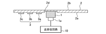
- the attachment portion 2c is formed as a digging portion 2d on the attachment surface 2a that is one surface of the wall member 2, and the radiation surface 1b of the ultrasonic sensor 1 is formed as the digging portion 2d. It may be attached to 2c. Since the radiation surface 1b of the ultrasonic sensor 1 is attached to the attachment portion 2c formed as the digging portion 2d, the thickness of the wall member 2 of the attachment portion 2c is reduced. Propagation distance of the ultrasonic wave becomes shorter.
- the material of the convex members 3a, 3b, 3c forming the rigidity changing portion 3 is not particularly limited, and the same material as the wall member 2 may be used, or a material different from the wall member 2 may be used. It is also possible to use a metal such as aluminum. As a material for the wall member 2, resin is generally used, but when resin and metal are compared, the density of metal is larger in the case of a convex member of the same size because the density of metal is higher. And the vibration of the wall member 2 can be further suppressed.
- the convex members 3a, 3b, 3c forming the rigidity changing portion 3 may be integrally formed, or convex members 3 a, 3 b, 3 c forming the rigidity changing portion 3 created separately from the wall member 2 may be attached to the wall member 2.
- the shape of the convex members 3 a, 3 b, 3 c forming the rigidity changing portion 3 has been described as a semi-annular shape, but not limited to this, the rigidity changing portion
- the convex members 3 a, 3 b, 3 c forming the shape 3 may be any shape that can change the rigidity of the wall member 2.
- the shape of the convex members 3a, 3b, 3c forming the rigidity changing portion 3 may be an arc as shown in FIG.
- the shape of the convex members 3a, 3b, 3c forming the rigidity changing portion 3 may be rectangular as shown in FIG.
- the shape and arrangement of the stiffness changing portion 3 are determined according to the vibration distribution.
- the shape of the convex members 3a, 3b, 3c forming the rigidity changing portion 3 is a rectangle, and the rectangles are all the same shape, but not limited to this, as shown in FIG. 9A
- the long sides of the convex members 3a, 3b, and 3c forming the rigidity changing portion 3 may be gradually shortened in the direction away from the ultrasonic sensor 1, or FIG. 9B.
- the rectangular long sides of the convex members 3 a, 3 b, 3 c forming the rigidity changing portion 3 may be gradually elongated in the direction away from the ultrasonic sensor 1. .
- the convex members 3a, 3b, 3c forming the rigidity changing portion 3 are formed in a semicircular shape, and as shown in FIG. 10A, the convex member 3a forming the rigidity changing portion 3 is formed. , 3b, 3c may have a shape in which the arc length gradually decreases in the direction away from the ultrasonic sensor 1, or as shown in FIG. 10B, convex members 3a, 3b forming the rigidity changing portion 3 , 3c may have a shape in which the arc length gradually increases in a direction away from the ultrasonic sensor 1.
- the stiffness changing portion 3 is arranged in a region sandwiched in two directions extending from the mounting portion 2c on the mounting surface 2a of the wall member 2, the stiffness changing portion 3 is ultrasonically You may make it provide so that a row
- rectangular convex members 3 a, 3 b, 3 c forming the rigidity changing portion 3 are arranged along a plurality of directions on the mounting surface 2 a of the wall member 2 with the mounting portion 2 c as a center. They may be arranged in rows.
- the rigidity change part 3 was demonstrated as what is formed with a convex-shaped member, as shown in FIG. 12, a groove
- the shape of the groove, that is, the concave portion is the same as the case where the rigidity changing portion 3 is formed by a convex member, as described with reference to FIGS. It may be a simple shape or an arrangement.
- the rigidity changing portion 3 may be formed by filling a concave groove provided on the mounting surface 2 a of the wall member 2 with a material different from that of the wall member 2.
- the shape of the groove is the same as that described with reference to FIGS. 7 to 11, such as a semi-annular shape, a rectangular shape, or the like, as in the case where the rigidity changing portion 3 is formed by a convex member. It is good also as arrangement.
- the rigidity changing portion 3 may be formed by combining materials and shapes as described above.
- the rigidity changing portion 3 is configured by providing a convex member made of the same material as the wall member 2, a convex member made of a material different from the wall member 2, and a groove in the wall member 2.
- the concave portion provided in the concave portion and the wall member 2 may be formed by combining at least two or more of those formed by filling a material different from that of the wall member 2.
- the rigidity change part 3 can also be formed by a plurality of convex members or concave parts having two or more different shapes such as a semicircular ring shape and an arc shape.
- the plurality of convex members forming the rigidity changing portion 3 or the width and height of the concave portions are described as being the same.
- the present invention is not limited to this, and the width and height are changed.
- a plurality of convex members or concave portions may be arranged on the mounting surface 2 a of the wall member 2.
- the rigidity changing portion 3 may be arranged at a position that becomes a peak or valley of the vibration displacement distribution in the vibration displacement distribution in the wall member 2.
- the direction in which the ultrasonic waves are radiated can be adjusted by changing the rigidity of the wall member 2 by the rigidity changing portion 3.
- Embodiment 2 FIG.
- the ultrasonic sensor 1 is provided on the mounting surface 2a of the planar wall member 2.
- the ultrasonic sensor 1 is attached to a through hole provided in the wall member 2 will be described.
- FIG. 14 and 15 are diagrams for explaining a schematic configuration of the ultrasonic transmission / reception device 100 according to Embodiment 2 of the present invention.
- FIG. 14 is a plan view seen from the attachment side of the ultrasonic sensor 1.
- FIG. 15 is a cross-sectional view taken along the line AA ′ of FIG.
- the configuration of the ultrasonic transmitting / receiving apparatus 100 according to the second embodiment of the present invention is the same as that described with reference to FIGS. 1 and 2 in the first embodiment. And redundant description is omitted.
- the ultrasonic transmitting / receiving apparatus 100 according to the second embodiment of the present invention differs from the ultrasonic transmitting / receiving apparatus 100 according to the first embodiment only in the structure in which the ultrasonic sensor 1 is attached to the wall member 2. Only points different from the first embodiment will be described below with reference to FIGS.
- a through hole 2 e is formed in the attachment portion 2 c of the wall member 2 to which the ultrasonic sensor 1 is attached.
- the ultrasonic sensor 1 is exposed to the through hole 2e so that the radiation surface 1b of the ultrasonic sensor 1 is exposed as a surface substantially the same as the surface 2b opposite to the mounting surface 2a of the wall member 2.
- the radiation surface 1b of the ultrasonic sensor 1 and the surface 2b opposite to the mounting surface 2a of the wall member 2 are substantially the same surface.
- the surface 2b opposite to the mounting surface 2a form a flat plane at the same height when viewed from the cross section, and the radiation surface 1b of the ultrasonic sensor 1 when viewed from the cross section It includes that the difference in height between the surface 2b opposite to the mounting surface 2a of the wall member 2 is small enough not to impair the appearance.
- the attachment surface 2a of the wall member 2 is provided with the rigidity changing portion 3 in a region sandwiched in two directions extending from the attachment portion 2c to which the ultrasonic sensor 1 is attached.
- the rigidity changing portion 3 is provided.
- the operation will be described.
- the basic operation of the ultrasonic transmitting / receiving apparatus 100 according to the second embodiment of the present invention is the same as the operation described in the first embodiment using the flowchart of FIG.
- the ultrasonic transmission / reception apparatus 100 according to the second embodiment of the present invention and the ultrasonic transmission / reception apparatus 100 according to the first embodiment differ only in how the ultrasonic waves are transmitted. To do.
- the radiation surface 1b of the ultrasonic sensor 1 vibrates.
- the ultrasonic sensor 1 is attached to the through hole 2e provided in the wall member 2, and the radiation surface 1b is the attachment surface of the wall member 2. Since it is exposed on the opposite side to 2a, the ultrasonic wave generated by the vibration of the radiation surface 1b is directly transmitted from the radiation surface 1b. Moreover, since the side surface of the ultrasonic sensor 1 vibrates with the vibration of the radiation surface 1b, the vibration propagates to the wall member 2, and the wall member 2 also vibrates.
- the rigidity changing portion 3 formed by the convex members 3a, 3b, 3c is provided on the mounting surface 2a of the wall member 2 in a region sandwiched in two directions extending from the mounting portion 2c. . That is, the mounting surface 2a of the wall member 2 has an asymmetric structure around the mounting portion 2c to which the ultrasonic sensor 1 is mounted. In the region where the rigidity changing portion 3 in the wall member 2 is provided, the ultrasonic sensor The vibration energy due to 1 is difficult to propagate. For this reason, the wall member 2 on the side where the rigidity changing portion 3 is provided is less likely to vibrate.
- the vibration energy from the ultrasonic sensor 1 propagates, and thus the wall member 2 vibrates more than the region in which the rigidity changing portion 3 is provided. Therefore, the vibration distribution in the wall member 2 is asymmetric.
- the ultrasonic wave is dominantly transmitted directly from the radiation surface 1b of the ultrasonic sensor 1, but the region of the wall member 2 where the rigidity changing portion 3 is not provided also vibrates. Ultrasonic waves are generated. For this reason, the generated ultrasonic waves interfere with each other, and the ultrasonic waves are radiated in a direction inclined toward the region where the rigidity changing portion 3 is provided.
- the direction in which the ultrasonic waves are radiated at an inclined angle is set to a direction opposite to the road surface.
- the sound wave transmitting / receiving device 100 By attaching the sound wave transmitting / receiving device 100 to the vehicle, ultrasonic waves radiated in the road surface direction are reduced, and reflected waves from the road surface are reduced.
- the side lobe component is also reduced, the directivity can be increased, and erroneous detection due to a reflected wave from the road surface can be reduced.
- the convex members 3a, 3b, 3c forming the rigidity changing portion 3 are arranged in a region sandwiched in two directions extending from the mounting portion 2c on the mounting surface 2a of the wall member 2.
- the ultrasonic transmission / reception apparatus 100 is set (see FIG. 5).
- the radiation direction of the ultrasonic wave transmitted from the ultrasonic sensor 1 is inclined in the direction opposite to the road surface, the ultrasonic wave radiated in the road surface direction is reduced, and the reflected wave from the road surface is reduced. Is reduced. And thereby, the false detection by the reflected wave from a road surface can be reduced.
- the convex members 3a, 3b, 3c or the concave portions forming the rigidity changing portion 3 of the second embodiment may be semicircular, arcuate, rectangular as in the first embodiment.
- the various shapes described in Embodiment Mode 1 can be used.
- the convex members 3a, 3b, 3c forming the rigidity changing portion 3 of the second embodiment or the arrangement of the concave portions are also provided, for example, as shown in FIG.
- the convex members 3a, 3b, 3c to be formed, or the concave portions can be arranged in rows along a plurality of directions on the mounting surface 2a of the wall member 2 with the mounting portion 2c as the center. .
- the direction in which the ultrasonic waves are emitted can be adjusted by changing the rigidity of the wall member 2 by the rigidity changing unit 3.
- the radiation surface 1b of the ultrasonic sensor 1 is exposed as a surface substantially the same as the surface 2b opposite to the mounting surface 2a of the wall member 2.
- the design is inferior.
- the ultrasonic wave transmitting / receiving apparatus 100 according to the second embodiment can adjust the direction in which the ultrasonic waves are radiated as described above, the direction in which the ultrasonic waves are radiated can be thereby inclined, and side lobes are suppressed. can do. As a result, false detection can be reduced.
- the ultrasonic transmission / reception device 100 is used in an obstacle detection system that detects an obstacle or the like around the vehicle, and the wall member 2 is, for example, an automobile.
- the use of the ultrasonic transmission / reception apparatus 100 of the present invention is not limited to a bumper of an automobile.
- the ultrasonic sensor 1 can be fixed to the outside of the lid of the liquid tank, and the ultrasonic transmission / reception device 100 can be used as a liquid level detection device for the liquid in the liquid tank.
- the ultrasonic sensor 1 can be fixed to the outer wall of the building or the inner side surface of the indoor wall, and the ultrasonic transmission / reception device 100 can be used as an intruder detection device.
- the radiation surface 1b of the ultrasonic sensor 1 is attached to the attachment surface 2a of the wall member 2 as shown in FIGS.
- the method of attaching the ultrasonic sensor 1 to the wall member 2 is as follows. An attachment portion 2c of the ultrasonic sensor 1 is set on the attachment surface 2a of the wall member 2 to which the radiation surface 1b of the ultrasonic sensor 1 is attached, and the region of the attachment surface 2a sandwiched in two directions extending from the attachment portion 2c as a starting point. Then, the rigidity changing portion 3 composed of the convex members 3a, 3b, 3c is formed. And the ultrasonic sensor 1 is attached to the attaching part 2c. In addition, the order of the process of setting the attaching part 2c and the process of forming the rigidity change part 3 is not ask
- the ultrasonic transmission / reception device 100 is configured as shown in FIGS. 1, 2, 14, and 15.
- the ultrasonic transmission / reception device 100 includes the ultrasonic sensor 1, By providing the rigidity changing portion 3, the above-described effects can be obtained.
- the invention of the present application can be freely combined with each embodiment, modified with any component in each embodiment, or omitted with any component in each embodiment. .
- the ultrasonic transmission / reception apparatus is configured such that the direction in which the ultrasonic waves are radiated can be adjusted by changing the rigidity of the wall member by the rigidity changing unit. It can be applied to a transmission / reception device.
Landscapes
- Engineering & Computer Science (AREA)
- Physics & Mathematics (AREA)
- Radar, Positioning & Navigation (AREA)
- Remote Sensing (AREA)
- Acoustics & Sound (AREA)
- Computer Networks & Wireless Communication (AREA)
- General Physics & Mathematics (AREA)
- Mechanical Engineering (AREA)
- Signal Processing (AREA)
- Measurement Of Velocity Or Position Using Acoustic Or Ultrasonic Waves (AREA)
- Transducers For Ultrasonic Waves (AREA)
Abstract
放射面(1b)を有する超音波センサ1と、超音波センサ(1)の放射面(1b)が取り付けられる取付部(2c)を有する取付面(2a)と、当該取付面(2a)に設けられるとともに取付部(2c)を起点として延びる2方向に挟まれた領域に設けられる剛性変化部(3)とを有する壁部材(2)とを備えた。
Description
この発明は、超音波の送受信を行う超音波送受信装置、超音波センサが取り付けられる壁部材、および、壁部材への超音波センサの取付方法に関するものである。
圧電素子等を用いた超音波センサは、例えば、障害物検知システムに利用される。障害物検知システムにおいて、超音波センサからは超音波が空気中に送信され、送信された超音波が障害物等により反射され、空気中を伝搬し、再び超音波センサで受信されることにより、障害物等が検知される。
一般に、超音波センサを車両周辺の障害物検知システムに利用する場合、車両のバンパ等の壁部材に、超音波センサを取り付けるための貫通孔が設けられる。そして、この貫通孔を使って、超音波センサの放射面がバンパ等の壁部材の外面と同一平面になるように、超音波センサが取り付けられる。そのため、例えば、バンパの外面から超音波センサの放射面が露出した状態となっており、デザイン性の面で好ましくない。また、バンパに貫通孔を設ける工程が必要となり、超音波センサを取り付けるときの作業が煩雑になる。
一般に、超音波センサを車両周辺の障害物検知システムに利用する場合、車両のバンパ等の壁部材に、超音波センサを取り付けるための貫通孔が設けられる。そして、この貫通孔を使って、超音波センサの放射面がバンパ等の壁部材の外面と同一平面になるように、超音波センサが取り付けられる。そのため、例えば、バンパの外面から超音波センサの放射面が露出した状態となっており、デザイン性の面で好ましくない。また、バンパに貫通孔を設ける工程が必要となり、超音波センサを取り付けるときの作業が煩雑になる。
そこで、例えば、特許文献1には、バンパ等の壁部材の内面に超音波センサを取り付けることにより、バンパに貫通孔を設ける工程を不要とするとともに、外観を損なわずに超音波を送受信する構成が開示されている。
特許文献1には、さらに、バンパにおける超音波センサの取付け部の周辺に振動が伝達し、バンパの広範囲が振動することで、放射される超音波のパターンにサイドローブが生じる等、指向性が不規則となるという問題を解消するため、間隙を介して超音波センサを取り囲む筒状剛性壁材を固定配置することにより、放射される超音波のパターンのサイドローブを低減するとともに、メインローブの範囲を適度に広くする技術が開示されている。
しかしながら、特許文献1に開示されているような超音波センサでは、遠方の障害物を検知する場合、あるいは、バンパの表面に固定される超音波センサが車両の低い位置に取り付けられた場合等には、メインローブが広いため、路面からの反射波を誤検知しやすいという課題があった。
しかしながら、特許文献1に開示されているような超音波センサでは、遠方の障害物を検知する場合、あるいは、バンパの表面に固定される超音波センサが車両の低い位置に取り付けられた場合等には、メインローブが広いため、路面からの反射波を誤検知しやすいという課題があった。
この発明は上記のような課題を解決するためになされたもので、超音波センサが取り付けられる壁部材の振動により発生する超音波が放射される方向を調整できる超音波送受信装置を提供することを目的とする。
この発明に係る超音波送受信装置は、放射面を有する超音波センサと、超音波センサの放射面が取り付けられる取付部を有する取付面と、当該取付面に設けられるとともに取付部を起点として延びる2方向に挟まれた領域に設けられる剛性変化部とを有する壁部材とを備えたものである。
この発明の超音波送受信装置は、上記の剛性変化部により、壁部材の剛性を変化させることで、超音波が放射される方向を調整できる。
以下、この発明の実施の形態について、図面を参照しながら詳細に説明する。
実施の形態1.
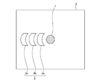
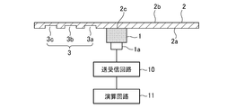
図1,図2は、この発明の実施の形態1に係る超音波送受信装置100の概略構成を説明する図であり、図1は、超音波センサ1の取り付け側から見た平面図であり、図2は、図1のA-A’線に沿う断面図である。
実施の形態1.
図1,図2は、この発明の実施の形態1に係る超音波送受信装置100の概略構成を説明する図であり、図1は、超音波センサ1の取り付け側から見た平面図であり、図2は、図1のA-A’線に沿う断面図である。
この実施の形態1に係る超音波送受信装置100は、図1,図2に示すように、超音波センサ1と、壁部材2と、壁部材2の剛性を変化させる剛性変化部3と、送受信回路10と、演算回路11とを備える。
超音波センサ1は、放射面1bを有する。超音波センサ1は、壁部材2の一表面である取付面2aに設定された取付部2cに、超音波センサ1の放射面1bが接触するように取り付けられる。超音波センサ1は、入出力端子1aにより送受信回路10に接続されている。
送受信回路10は、送信回路(図示省略)と受信回路(図示省略)を備え、送信回路と受信回路とは電気的に接続されている。また、送受信回路10には、演算回路11が電気的に接続されている。
演算回路11は、既存の、一般的に知られる技術を用いて、障害物等の対象物までの相対距離、あるいは、伝達音速等を算出する。相対距離について、具体的には、演算回路11は、超音波の送信から、超音波が障害物で反射し、再び当該反射した超音波を受信するまでの時間と、所定の音速に基づき、相対距離を算出する。
なお、送受信回路10および演算回路11は、それぞれ電源(図示省略)に接続されている。
超音波センサ1は、放射面1bを有する。超音波センサ1は、壁部材2の一表面である取付面2aに設定された取付部2cに、超音波センサ1の放射面1bが接触するように取り付けられる。超音波センサ1は、入出力端子1aにより送受信回路10に接続されている。
送受信回路10は、送信回路(図示省略)と受信回路(図示省略)を備え、送信回路と受信回路とは電気的に接続されている。また、送受信回路10には、演算回路11が電気的に接続されている。
演算回路11は、既存の、一般的に知られる技術を用いて、障害物等の対象物までの相対距離、あるいは、伝達音速等を算出する。相対距離について、具体的には、演算回路11は、超音波の送信から、超音波が障害物で反射し、再び当該反射した超音波を受信するまでの時間と、所定の音速に基づき、相対距離を算出する。
なお、送受信回路10および演算回路11は、それぞれ電源(図示省略)に接続されている。
剛性変化部3は、壁部材2の剛性を変化させるための部位であり、壁部材2の取付面2aに設けられるとともに、超音波センサ1が取り付けられる取付部2cを起点として延びる2方向に挟まれた領域に設けられる。図1においては、超音波センサ1が取り付けられる取付部2cを起点として延びる2方向を、X,X’で示している。なお、ここでは、一例として、図1では、X方向の直線とX’方向の直線との間の角度が180°となるようにしているが、超音波センサ1が取り付けられる取付部2cを起点として延びる2方向の直線で形成される角度は180°に限らない。
また、ここでは、図1,2に示すように、一例として、剛性変化部3は、予め決められた形状を有した凸状の部材3a,3b,3cで形成され、剛性変化部3の形状は、半円環状をしているものとする。また、この凸状の部材3a,3b,3cは、任意の間隔で、少なくとも1つ以上設けられる。
ここでは、剛性変化部3を形成する凸状の部材3a,3b,3cは、図1,2に示すように、3つ設けられるものとしているが、これに限らず、凸状の部材3a,3b,3cは、1つ設けられるものであってもよいし、2つ設けられるようにしてもよいし、4つ以上に設けられるようにしてもよい。すなわち、剛性変化部3を形成する凸状の部材3a,3b,3cは、少なくとも1つ以上設けられるものであればよい。
ここでは、3つ設けられた凸状の部材3a,3b,3cの幅および高さは全て同一であるものとする。
また、ここでは、図1,2に示すように、一例として、剛性変化部3は、予め決められた形状を有した凸状の部材3a,3b,3cで形成され、剛性変化部3の形状は、半円環状をしているものとする。また、この凸状の部材3a,3b,3cは、任意の間隔で、少なくとも1つ以上設けられる。
ここでは、剛性変化部3を形成する凸状の部材3a,3b,3cは、図1,2に示すように、3つ設けられるものとしているが、これに限らず、凸状の部材3a,3b,3cは、1つ設けられるものであってもよいし、2つ設けられるようにしてもよいし、4つ以上に設けられるようにしてもよい。すなわち、剛性変化部3を形成する凸状の部材3a,3b,3cは、少なくとも1つ以上設けられるものであればよい。
ここでは、3つ設けられた凸状の部材3a,3b,3cの幅および高さは全て同一であるものとする。
動作について説明する。
図3は、この発明の実施の形態1に係る超音波送受信装置100の動作について説明するフローチャートである。
送受信回路10の送信回路は、超音波センサ1に、電気信号を印加する(ステップST301)。
ステップST301で送受信回路10から電気信号が印加されると、超音波センサ1は励振され、これにより、超音波センサ1は、壁部材2を介して、壁部材2の取付面2aと反対側の空間に、超音波を送信する(ステップST302)。
図3は、この発明の実施の形態1に係る超音波送受信装置100の動作について説明するフローチャートである。
送受信回路10の送信回路は、超音波センサ1に、電気信号を印加する(ステップST301)。
ステップST301で送受信回路10から電気信号が印加されると、超音波センサ1は励振され、これにより、超音波センサ1は、壁部材2を介して、壁部材2の取付面2aと反対側の空間に、超音波を送信する(ステップST302)。
ステップST302において超音波センサ1が送信した超音波は、壁部材2の取付面2aと反対側の空間に存在する障害物等で反射され、再び壁部材2の取付面2aと反対側の表面2bに達し、超音波センサ1は、壁部材2を介して、当該反射された超音波を受信する(ステップST303)。
また、このステップST303において、超音波センサ1は、超音波を受信すると、当該受信した超音波に基づく処理を行い、受信した超音波を電気信号に変換し、送受信回路10の受信回路に送信する。
送受信回路10の受信回路は、超音波センサ1から電気信号を受信し、受信した電気信号を、演算回路11に送信する(ステップST304)。
また、このステップST303において、超音波センサ1は、超音波を受信すると、当該受信した超音波に基づく処理を行い、受信した超音波を電気信号に変換し、送受信回路10の受信回路に送信する。
送受信回路10の受信回路は、超音波センサ1から電気信号を受信し、受信した電気信号を、演算回路11に送信する(ステップST304)。
演算回路11は、ステップST304で送信された電気信号を受信し、当該受信した電気信号に基づき、障害物等までの相対距離、あるいは、伝達音速等を算出する(ステップST305)。なお、演算回路11は、送受信回路10での相対距離等、あるいは、伝達音速等の算出を、既存の、一般的に知られる技術を用いて行えばよいため、詳細な説明を省略する。
ここで、ステップST302の動作についてさらに詳細に説明する。
超音波センサ1に電気信号が印加されると、放射面1bが振動する。超音波センサ1は、壁部材2の取付面2aに設定された取付部2cに、超音波センサ1の放射面1bが接触するように取り付けられている。このため、放射面1bの振動が壁部材2に伝搬し、壁部材2が振動する。この振動により、壁部材2の取付面2aと反対側の表面2bより超音波が送信される。
この時、壁部材2では、放射面1bが接触する取付部2cの振動変位が大きくなり、当該放射面1bが接触する取付部2cの振動変位が支配的にはなるが、放射面1bが接触する取付部2c以外の壁部材2も振動する。
超音波センサ1に電気信号が印加されると、放射面1bが振動する。超音波センサ1は、壁部材2の取付面2aに設定された取付部2cに、超音波センサ1の放射面1bが接触するように取り付けられている。このため、放射面1bの振動が壁部材2に伝搬し、壁部材2が振動する。この振動により、壁部材2の取付面2aと反対側の表面2bより超音波が送信される。
この時、壁部材2では、放射面1bが接触する取付部2cの振動変位が大きくなり、当該放射面1bが接触する取付部2cの振動変位が支配的にはなるが、放射面1bが接触する取付部2c以外の壁部材2も振動する。
しかしながら、この実施の形態1では、壁部材2の取付面2aには、取付部2cを起点として延びる2方向に挟まれた領域に、凸状の部材3a,3b,3cで形成される剛性変化部3が設けられている。すなわち、壁部材2の取付面2aは、超音波センサ1が取り付けられた取付部2cを中心として非対称な構造となっており、壁部材2における剛性変化部3を設けた領域では、超音波センサ1による振動のエネルギーが伝搬しにくくなっている。このため、剛性変化部3を設けた側の壁部材2が振動しにくくなる。
一方、壁部材2における剛性変化部3を設けていない領域では、超音波センサ1による振動のエネルギーが伝搬するため、壁部材2における剛性変化部3を設けた領域よりも振動する。よって、壁部材2における振動分布は非対称となる。
一方、壁部材2における剛性変化部3を設けていない領域では、超音波センサ1による振動のエネルギーが伝搬するため、壁部材2における剛性変化部3を設けた領域よりも振動する。よって、壁部材2における振動分布は非対称となる。
この実施の形態1では、上述したように、壁部材2における超音波センサ1の放射面1bが接触する取付部2cから支配的に超音波が送信されるが、壁部材2における剛性変化部3を設けていない領域も振動し、超音波が生じる。このため、生じた超音波が互いに干渉し、超音波は剛性変化部3を設けた領域の側に傾斜した方向に放射される。
ここで、図4は、この実施の形態1に係る超音波送受信装置100の効果を説明する図である。
なお、図4は、この実施の形態1に係る超音波送受信装置100に関し、有限要素法を用いて求めた指向特性の計算結果を示している。また、図4は、図1,2に示すように、超音波センサ1が取り付けられた取付部2cを起点として、壁部材2の取付面2aにおける左側に、剛性変化部3を形成する凸状の部材3a,3b,3cが複数配置された超音波送受信装置100に関する指向特性の計算結果を示したものである。
なお、図4は、この実施の形態1に係る超音波送受信装置100に関し、有限要素法を用いて求めた指向特性の計算結果を示している。また、図4は、図1,2に示すように、超音波センサ1が取り付けられた取付部2cを起点として、壁部材2の取付面2aにおける左側に、剛性変化部3を形成する凸状の部材3a,3b,3cが複数配置された超音波送受信装置100に関する指向特性の計算結果を示したものである。
図4において、この実施の形態1に係る超音波送受信装置100の指向特性計算結果を、第1の指向特性計算結果(A)として実線で示している。また、図1および図2を用いて説明したような剛性変化部3を設けず、超音波センサ1、送受信回路10、および、演算回路11からなる一般的な構成の超音波送受信装置の指向特性計算結果についても、第2の指向特性計算結果(B)として破線で示している。
図4では、横軸は、超音波送受信装置100の正面方向、すなわち、壁部材2に対して取付部2cの略中心を通って垂直な方向を0°とし、図2における取付部2cの略中心を基準に左側への傾きを負の値、右側への傾きを正の値した角度で表わしており、縦軸は、放射音圧レベルを示している。
剛性変化部3を設けない一般的な超音波送受信装置の場合、第2の指向特性計算結果(B)として示すように、放射音圧レベルは0°方向近傍で最大値を示している。
一方、この実施の形態1に係る超音波送受信装置100の場合、第1の指向特性計算結果(A)として示すように、放射音圧レベルは-5°方向近傍で最大値を示しており、放射音圧レベルが最大値を示す角度はマイナス側にシフトしている。
よって、この実施の形態1に係る超音波送受信装置100では、超音波が、正面方向から傾斜した方向に放射されることがわかる。
また、第2の指向特性計算結果(B)における±80°方向の音圧レベルも、剛性変化部3を設ける超音波送受信装置100による第1の指向特性計算結果(A)では低減しており、剛性変化部3を設けることで、サイドローブを抑圧する効果が得られることがわかる。
剛性変化部3を設けない一般的な超音波送受信装置の場合、第2の指向特性計算結果(B)として示すように、放射音圧レベルは0°方向近傍で最大値を示している。
一方、この実施の形態1に係る超音波送受信装置100の場合、第1の指向特性計算結果(A)として示すように、放射音圧レベルは-5°方向近傍で最大値を示しており、放射音圧レベルが最大値を示す角度はマイナス側にシフトしている。
よって、この実施の形態1に係る超音波送受信装置100では、超音波が、正面方向から傾斜した方向に放射されることがわかる。
また、第2の指向特性計算結果(B)における±80°方向の音圧レベルも、剛性変化部3を設ける超音波送受信装置100による第1の指向特性計算結果(A)では低減しており、剛性変化部3を設けることで、サイドローブを抑圧する効果が得られることがわかる。
なお、この実施の形態1では、一例として、超音波送受信装置100は、車両周辺の障害物を検知する障害物検知システムに用いられるものとし、壁部材2は、例えば、自動車等のバンパを想定している。壁部材2がバンパの場合、壁部材2の一表面である取付面2aは、バンパの内面となる。
この実施の形態1に係る超音波送受信装置100を障害物検知システムに利用する場合、超音波が傾斜した角度に放射される方向を路面とは逆の方向に設定して超音波送受信装置100を車両に取り付けることで、路面方向へ放射される超音波が低減し、路面からの反射波が低減する。
また、サイドローブ成分も低減するため、指向性を高めることができ、また、路面からの反射波による誤検知を減らすことができる。
また、サイドローブ成分も低減するため、指向性を高めることができ、また、路面からの反射波による誤検知を減らすことができる。
図5は、この実施の形態1に係る超音波送受信装置100を障害物検知システムに適用し、路面方向へ放射される超音波が低減されるように、壁部材2、すなわち、車両のバンパに取り付けた一例を説明する図である。なお、図5は、超音波センサ1の取り付け側から見た平面図である。
図5に示すように、剛性変化部3を形成する凸状の部材3a,3b,3cが、壁部材2の取付面2aにおいて、取付部2cを起点として延びる2方向に挟まれた領域に配置されるように、超音波送受信装置100を設定する。
このように設定することで、超音波センサ1から送信される超音波の放射方向が、路面とは逆の方向に傾斜され、路面方向へ放射される超音波が低減し、路面からの反射波が低減する。そして、これにより、路面からの反射波による誤検知を減らすことができる。
図5に示すように、剛性変化部3を形成する凸状の部材3a,3b,3cが、壁部材2の取付面2aにおいて、取付部2cを起点として延びる2方向に挟まれた領域に配置されるように、超音波送受信装置100を設定する。
このように設定することで、超音波センサ1から送信される超音波の放射方向が、路面とは逆の方向に傾斜され、路面方向へ放射される超音波が低減し、路面からの反射波が低減する。そして、これにより、路面からの反射波による誤検知を減らすことができる。
なお、この実施の形態1において、超音波送受信装置100は、車両周辺に存在する障害物を検知する障害物検知装置とし、超音波センサ1は、車両の前後のバンパに取り付けられることを想定しており、壁部材2は、車両のバンパに相当するものとしているので、壁部材2は、ポリプロリレンやウレタン等の剛性樹脂成型品とするが、壁部材2は特に限定されるものではなく、超音波の伝搬に適した材質や形状であればよい。
また、超音波センサ1の壁部材2への固定方法としては、例えば、超音波センサ1の放射面1bと壁部材2とが接着固定された構造とすればよい。あるいは、超音波センサ1と壁部材2の間に、超音波センサ1の音響インピーダンスと壁部材2の音響インピーダンスの中間の音響インピーダンスを有する音響整合層を介した構造としてもよい。すなわち、超音波センサ1の放射面1bが、超音波センサ1の音響インピーダンスと壁部材2の音響インピーダンスの中間の音響インピーダンスを有する音響整合層を介して、取付部2cに取り付けられるようにしてもよい。超音波センサ1の放射面1bが、音響整合層を介して取付部2cに取り付けられるようにすることで、超音波センサ1と壁部材2との境界での反射が減少し、超音波センサ1から壁部材2へ伝搬する超音波が増大し、壁部材2から放射される超音波の音圧が向上する。
超音波センサ1が壁部材2に固定されていれば、その他の固定方法を用いてもよい。
超音波センサ1が壁部材2に固定されていれば、その他の固定方法を用いてもよい。
また、図6に示すように、壁部材2の取付面2aに掘り込み部2dを設け、掘り込み部2dの位置に超音波センサ1を取り付けた構成としてもよい。すなわち、取付部2cは、壁部材2の一面である取付面2aに掘り込み部2dとして形成されたものとし、超音波センサ1の放射面1bが、当該掘り込み部2dとして形成された取付部2cに取り付けられるものとしてもよい。超音波センサ1の放射面1bが、当該掘り込み部2dとして形成された取付部2cに取り付けられるようにすることで、取付部2cの壁部材2の厚さが減少するため、壁部材2中における超音波の伝搬距離が短くなる。これにより、壁部材2中での伝搬に伴う超音波の減衰が小さくなり、結果として、壁部材2から放射される超音波の音圧が向上する。
また、剛性変化部3を形成する凸状の部材3a,3b,3cの材料は、特に限定するものではなく、壁部材2と同一の材料としてもよいし、壁部材2とは別の材料を用いて、アルミ等の金属としてもよい。なお、壁部材2の材料としては、樹脂が一般的ではあるが、樹脂と金属を比較した場合、金属の方が密度は大きいため、同サイズの凸状の部材では、金属とした方が剛性は高くなり、より壁部材2の振動を抑圧することができる。
剛性変化部3を形成する凸状の部材3a,3b,3cの材料を壁部材2と同一の材料とする場合は、剛性変化部3を形成する凸状の部材3a,3b,3cと壁部材2とを一体で成形してもよいし、壁部材2とは別に作成した剛性変化部3を形成する凸状の部材3a,3b,3cを、壁部材2に取り付けるようにしてもよい。
また、剛性変化部3を形成する凸状の部材3a,3b,3cの材料は、特に限定するものではなく、壁部材2と同一の材料としてもよいし、壁部材2とは別の材料を用いて、アルミ等の金属としてもよい。なお、壁部材2の材料としては、樹脂が一般的ではあるが、樹脂と金属を比較した場合、金属の方が密度は大きいため、同サイズの凸状の部材では、金属とした方が剛性は高くなり、より壁部材2の振動を抑圧することができる。
剛性変化部3を形成する凸状の部材3a,3b,3cの材料を壁部材2と同一の材料とする場合は、剛性変化部3を形成する凸状の部材3a,3b,3cと壁部材2とを一体で成形してもよいし、壁部材2とは別に作成した剛性変化部3を形成する凸状の部材3a,3b,3cを、壁部材2に取り付けるようにしてもよい。
また、以上の説明では、図1に示すように、剛性変化部3を形成する凸状の部材3a,3b,3cの形状を、半円環状として説明したが、これに限らず、剛性変化部3を形成する凸状の部材3a,3b,3cが、壁部材2の剛性を変化させることのできる形状であればよい。
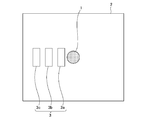
例えば、剛性変化部3を形成する凸状の部材3a,3b,3cの形状は、図7に示すように、円弧状としてもよい。あるいは、剛性変化部3を形成する凸状の部材3a,3b,3cの形状は、図8に示すように、矩形としてもよい。なお、超音波センサ1の特性により、壁部材2での振動分布が変化する。よって、剛性変化部3の形状、配置は、当該振動分布に合わせて決定するようにする。
また、図8では、剛性変化部3を形成する凸状の部材3a,3b,3cの形状を、矩形とし、当該矩形は全て同一形状としているが、これに限らず、図9Aに示すように、剛性変化部3を形成する凸状の部材3a,3b,3cの矩形の長辺が、超音波センサ1から離れる方向に向かって徐々に短くなる形状となるようにしてもよいし、図9Bに示すように、剛性変化部3を形成する凸状の部材3a,3b,3cの矩形の長辺が、超音波センサ1から離れる方向に向かって徐々に長くなる形状となるようにしてもよい。
例えば、剛性変化部3を形成する凸状の部材3a,3b,3cの形状は、図7に示すように、円弧状としてもよい。あるいは、剛性変化部3を形成する凸状の部材3a,3b,3cの形状は、図8に示すように、矩形としてもよい。なお、超音波センサ1の特性により、壁部材2での振動分布が変化する。よって、剛性変化部3の形状、配置は、当該振動分布に合わせて決定するようにする。
また、図8では、剛性変化部3を形成する凸状の部材3a,3b,3cの形状を、矩形とし、当該矩形は全て同一形状としているが、これに限らず、図9Aに示すように、剛性変化部3を形成する凸状の部材3a,3b,3cの矩形の長辺が、超音波センサ1から離れる方向に向かって徐々に短くなる形状となるようにしてもよいし、図9Bに示すように、剛性変化部3を形成する凸状の部材3a,3b,3cの矩形の長辺が、超音波センサ1から離れる方向に向かって徐々に長くなる形状となるようにしてもよい。
また、図10に示すように、剛性変化部3を形成する凸状の部材3a,3b,3cを半円弧状とし、図10Aに示すように、剛性変化部3を形成する凸状の部材3a,3b,3cの円弧長が、超音波センサ1から離れる方向に向かって徐々に短くなる形状としてもよいし、図10Bに示すように、剛性変化部3を形成する凸状の部材3a,3b,3cの円弧長が、超音波センサ1から離れる方向に向かって徐々に長くなる形状としてもよい。
また、剛性変化部3が、壁部材2の取付面2a上の、取付部2cを基点として延びる2方向に挟まれる領域に配置されるようになっていれば、剛性変化部3は、超音波センサ1から離れる複数方向に沿って列をなすように設けられるようにしてもよい。
例えば、図11に示すように、剛性変化部3を形成する矩形の凸状の部材3a,3b,3cを、取付部2cを中心として、壁部材2の取付面2a上の複数方向に沿って列をなすように配置してもよい。
例えば、図11に示すように、剛性変化部3を形成する矩形の凸状の部材3a,3b,3cを、取付部2cを中心として、壁部材2の取付面2a上の複数方向に沿って列をなすように配置してもよい。
また、以上の説明では、剛性変化部3が凸状の部材により形成されるものとして説明したが、これに限らず、図12に示すように、壁部材2の取付面2aに溝を設け、当該溝による凹部が剛性変化部3を形成するものとしてもよい。
この時、溝、すなわち、凹部の形状は、剛性変化部3が凸状の部材により形成されるものとした場合と同様、半円環状、矩形等、図7~図11を用いて説明したような形状、あるいは、配置としてもよい。
また、図13に示すように、剛性変化部3は、壁部材2の取付面2aに設けた凹状の溝に、壁部材2とは異なる材料を満たして形成されるようにしてもよい。この場合、溝の形状は、剛性変化部3を、凸状の部材により形成されるものとした場合同様、半円環状、矩形等、図7~図11を用いて説明したような形状、あるいは、配置としてもよい。
この時、溝、すなわち、凹部の形状は、剛性変化部3が凸状の部材により形成されるものとした場合と同様、半円環状、矩形等、図7~図11を用いて説明したような形状、あるいは、配置としてもよい。
また、図13に示すように、剛性変化部3は、壁部材2の取付面2aに設けた凹状の溝に、壁部材2とは異なる材料を満たして形成されるようにしてもよい。この場合、溝の形状は、剛性変化部3を、凸状の部材により形成されるものとした場合同様、半円環状、矩形等、図7~図11を用いて説明したような形状、あるいは、配置としてもよい。
また、剛性変化部3は、上述したような材料、形状を組み合わせて形成されるようにしてもよい。例えば、剛性変化部3は、壁部材2と同一の材料で構成される凸状の部材、壁部材2と異なる材料で構成される凸状の部材、壁部材2に溝を設けて構成される凹部、壁部材2に設けられた凹部に、壁部材2とは異なる材料を埋めて構成されるもののうち、少なくとも2つ以上を組み合わせて形成されるようにすることもできる。
また、半円環状と円弧状等、異なる2つ以上の形状を有する複数の凸状の部材または凹部により剛性変化部3を形成することもできる。
また、半円環状と円弧状等、異なる2つ以上の形状を有する複数の凸状の部材または凹部により剛性変化部3を形成することもできる。
また、以上の説明では、例えば、剛性変化部3を形成する複数の凸状の部材、あるいは、凹部の幅、高さを同一として説明したが、これに限らず、幅、高さを変化させた複数の凸状の部材、あるいは、凹部が、壁部材2の取付面2aに配置されるようにしてもよい。
また、剛性変化部3は、壁部材2での振動変位分布において、振動変位分布の山、もしくは、谷となる位置に配置されるようにするとよい。
また、剛性変化部3は、壁部材2での振動変位分布において、振動変位分布の山、もしくは、谷となる位置に配置されるようにするとよい。
以上のように、実施の形態1によれば、剛性変化部3により、壁部材2の剛性を変化させることで、超音波が放射される方向を調整することができる。
実施の形態2.
実施の形態1では、超音波送受信装置100に関し、超音波センサ1は、平面状の壁部材2の取付面2aに設けられるものとしていた。
この実施の形態2では、超音波センサ1を、壁部材2に設けられた貫通孔に取り付けるようにする実施の形態について説明する。
実施の形態1では、超音波送受信装置100に関し、超音波センサ1は、平面状の壁部材2の取付面2aに設けられるものとしていた。
この実施の形態2では、超音波センサ1を、壁部材2に設けられた貫通孔に取り付けるようにする実施の形態について説明する。
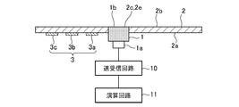
図14,図15は、この発明の実施の形態2に係る超音波送受信装置100の概略構成を説明する図であり、図14は、超音波センサ1の取り付け側から見た平面図であり、図15は、図14のA-A’線に沿う断面図である。
なお、この発明の実施の形態2に係る超音波送受信装置100の構成は、実施の形態1において、図1,図2を用いて説明した構成と同様であるので、同様の構成には同じ符号を付し、重複した説明を省略する。
この発明の実施の形態2に係る超音波送受信装置100は、実施の形態1に係る超音波送受信装置100とは、超音波センサ1が壁部材2に取り付けられる構造が異なるのみであるので、当該実施の形態1とは異なる点のみ、図14,図15を用いて以下説明する。
なお、この発明の実施の形態2に係る超音波送受信装置100の構成は、実施の形態1において、図1,図2を用いて説明した構成と同様であるので、同様の構成には同じ符号を付し、重複した説明を省略する。
この発明の実施の形態2に係る超音波送受信装置100は、実施の形態1に係る超音波送受信装置100とは、超音波センサ1が壁部材2に取り付けられる構造が異なるのみであるので、当該実施の形態1とは異なる点のみ、図14,図15を用いて以下説明する。
図14,図15に示すように、実施の形態2に係る超音波送受信装置100では、超音波センサ1が取り付けられる壁部材2の取付部2cには、貫通孔2eが形成されている。そして、超音波センサ1は、当該貫通孔2eに、超音波センサ1の放射面1bが壁部材2の取付面2aとは反対側の表面2bと略同一の面として露出する状態となるように、壁部材2に取り付けられる。
なお、ここで、超音波センサ1の放射面1bと壁部材2の取付面2aとは反対側の表面2bとが略同一の面であるとは、超音波センサ1の放射面1bと壁部材2の取付面2aとは反対側の表面2bとが、断面から見たときに同じ高さで平らな平面を形成すること、および、断面から見たときの超音波センサ1の放射面1bと壁部材2の取付面2aとは反対側の表面2bの高さの差が、外観を損なわない程度に小さいことを含む。
なお、ここで、超音波センサ1の放射面1bと壁部材2の取付面2aとは反対側の表面2bとが略同一の面であるとは、超音波センサ1の放射面1bと壁部材2の取付面2aとは反対側の表面2bとが、断面から見たときに同じ高さで平らな平面を形成すること、および、断面から見たときの超音波センサ1の放射面1bと壁部材2の取付面2aとは反対側の表面2bの高さの差が、外観を損なわない程度に小さいことを含む。
また、実施の形態1同様、壁部材2の取付面2aには、超音波センサ1が取り付けられる取付部2cを起点として延びる2方向に挟まれた領域に剛性変化部3が設けられる。ここでは、一例として、剛性変化部3を形成する半円環状の凸状の部材3a,3b,3cが3つ設けられるものとしている。
動作について説明する。
この発明の実施の形態2に係る超音波送受信装置100の基本的な動作は、実施の形態1において、図3のフローチャートを用いて説明した動作と同様であるため、重複した説明を省略する。
この発明の実施の形態2に係る超音波送受信装置100と、実施の形態1に係る超音波送受信装置100とでは、超音波の送信のされ方が異なるのみであるので、当該異なる点について以下説明する。
この発明の実施の形態2に係る超音波送受信装置100の基本的な動作は、実施の形態1において、図3のフローチャートを用いて説明した動作と同様であるため、重複した説明を省略する。
この発明の実施の形態2に係る超音波送受信装置100と、実施の形態1に係る超音波送受信装置100とでは、超音波の送信のされ方が異なるのみであるので、当該異なる点について以下説明する。
超音波センサ1に送受信回路10の送信回路からの電気信号が印加されると、超音波センサ1の放射面1bが振動する。この時、この実施の形態2に係る超音波送受信装置100では、超音波センサ1は、壁部材2に設けられた貫通孔2eに取り付けられており、放射面1bが、壁部材2の取付面2aとは反対側に露出しているため、放射面1bの振動により生じた超音波が、放射面1bから直接送信される。
また、放射面1bの振動に伴い、超音波センサ1の側面も振動するため、その振動が壁部材2に伝搬し、壁部材2も振動する。
また、放射面1bの振動に伴い、超音波センサ1の側面も振動するため、その振動が壁部材2に伝搬し、壁部材2も振動する。
しかしながら、壁部材2の取付面2aには、取付部2cを起点として延びる2方向に挟まれた領域に、凸状の部材3a,3b,3cで形成される剛性変化部3が設けられている。すなわち、壁部材2の取付面2aは、超音波センサ1が取り付けられた取付部2cを中心として非対称な構造となっており、壁部材2における剛性変化部3を設けた領域では、超音波センサ1による振動のエネルギーが伝搬しにくくなっている。このため、剛性変化部3を設けた側の壁部材2が振動しにくくなる。
一方、壁部材2における剛性変化部3を設けていない領域では、超音波センサ1による振動のエネルギーが伝搬するため、壁部材2における剛性変化部3を設けた領域よりも振動する。よって、壁部材2における振動分布は非対称となる。
一方、壁部材2における剛性変化部3を設けていない領域では、超音波センサ1による振動のエネルギーが伝搬するため、壁部材2における剛性変化部3を設けた領域よりも振動する。よって、壁部材2における振動分布は非対称となる。
このように、この実施の形態2においては、超音波センサ1の放射面1bから直接、支配的に超音波が送信されるが、壁部材2における剛性変化部3を設けていない領域も振動し、超音波が生じる。このため、生じた超音波が互いに干渉し、超音波は剛性変化部3を設けた領域の側に傾斜した方向に放射される。
以上のことから、この実施の形態2に係る超音波送受信装置100を障害物検知システムに利用する場合、超音波が傾斜した角度に放射される方向を路面とは逆の方向に設定して超音波送受信装置100を車両に取り付けることで、路面方向へ放射される超音波が低減し、路面からの反射波が低減する。
また、サイドローブ成分も低減するため、指向性を高めることができ、また、路面からの反射波による誤検知を減らすことができる。
また、サイドローブ成分も低減するため、指向性を高めることができ、また、路面からの反射波による誤検知を減らすことができる。
具体的には、例えば、剛性変化部3を形成する凸状の部材3a,3b,3cが、壁部材2の取付面2aにおいて、取付部2cを起点として延びる2方向に挟まれた領域に配置されるように、超音波送受信装置100を設定する(図5参照)。
このように設定することで、超音波センサ1から送信される超音波の放射方向が、路面とは逆の方向に傾斜され、路面方向へ放射される超音波が低減し、路面からの反射波が低減する。そして、これにより、路面からの反射波による誤検知を減らすことができる。
このように設定することで、超音波センサ1から送信される超音波の放射方向が、路面とは逆の方向に傾斜され、路面方向へ放射される超音波が低減し、路面からの反射波が低減する。そして、これにより、路面からの反射波による誤検知を減らすことができる。
なお、この実施の形態2の剛性変化部3を形成する凸状の部材3a,3b,3c、あるいは、凹部の形状は、実施の形態1同様、半円環状としても、円弧状としても、矩形としてもよく、実施の形態1で説明した様々な形状とすることが可能である。
また、この実施の形態2の剛性変化部3を形成する凸状の部材3a,3b,3c、あるいは、凹部の配置についても、実施の形態1で説明したように、例えば、剛性変化部3を形成する凸状の部材3a,3b,3c、あるいは、凹部を、取付部2cを中心として、壁部材2の取付面2a上の複数方向に沿って列をなすように配置することが可能である。
また、この実施の形態2の剛性変化部3を形成する凸状の部材3a,3b,3c、あるいは、凹部の配置についても、実施の形態1で説明したように、例えば、剛性変化部3を形成する凸状の部材3a,3b,3c、あるいは、凹部を、取付部2cを中心として、壁部材2の取付面2a上の複数方向に沿って列をなすように配置することが可能である。
以上のように、この実施の形態2によると、剛性変化部3により、壁部材2の剛性を変化させることで、超音波が放射される方向を調整できる。
なお、この実施の形態2の超音波送受信装置100では、超音波センサ1の放射面1bが壁部材2の取付面2aとは反対側の表面2bと略同一の面として露出する状態となるため、デザイン性は劣る。しかしながら、この実施の形態2の超音波送受信装置100では、上述のとおり、超音波が放射される方向を調整できるため、これにより、超音波の放射方向を傾斜させることができ、サイドローブを抑圧することができる。その結果、誤検知を低減できる。
なお、この実施の形態2の超音波送受信装置100では、超音波センサ1の放射面1bが壁部材2の取付面2aとは反対側の表面2bと略同一の面として露出する状態となるため、デザイン性は劣る。しかしながら、この実施の形態2の超音波送受信装置100では、上述のとおり、超音波が放射される方向を調整できるため、これにより、超音波の放射方向を傾斜させることができ、サイドローブを抑圧することができる。その結果、誤検知を低減できる。
なお、上述した実施の形態1,2では、一例として、超音波送受信装置100を、車両周辺の障害物等を検知する障害物検知システムに用いられるものとし、壁部材2は、例えば、自動車のバンパを想定しているものとして説明したが、この発明の超音波送受信装置100の使用は、自動車のバンパのみに限られるものではない。例えば、超音波センサ1を、液体タンクの蓋の外側に固定して、超音波送受信装置100を、液体タンク内の液体の液面検知装置として使用することもできるし、超音波送受信装置100を、例えば、硫化水素、亜硫酸、亜硝酸、塩素等、特に腐食性ガスが発生する液体あるいはガソリンなどの液体燃料の液面検知装置として使用してもよい。また、超音波センサ1を建物の外壁や室内の壁の内側面に固定して、超音波送受信装置100を侵入者の検知装置として使用することもできる。
実施の形態1,2では、それぞれ、図1,2,14,15のように、超音波センサ1の放射面1bが、壁部材2の取付面2aに取り付けられている状態を示した。
壁部材2への超音波センサ1の取付方法は、以下のとおりである。
超音波センサ1の放射面1bが取り付けられる壁部材2の取付面2aに超音波センサ1の取付部2cを設定し、取付面2aにおける取付部2cを起点として延びる2方向に挟まれた領域に、凸状の部材3a,3b,3cからなる剛性変化部3を形成する。そして、取付部2cに、超音波センサ1を取り付ける。
なお、取付部2cを設定する工程、剛性変化部3を形成する工程の順序は問わない。
壁部材2への超音波センサ1の取付方法は、以下のとおりである。
超音波センサ1の放射面1bが取り付けられる壁部材2の取付面2aに超音波センサ1の取付部2cを設定し、取付面2aにおける取付部2cを起点として延びる2方向に挟まれた領域に、凸状の部材3a,3b,3cからなる剛性変化部3を形成する。そして、取付部2cに、超音波センサ1を取り付ける。
なお、取付部2cを設定する工程、剛性変化部3を形成する工程の順序は問わない。
また、この発明の実施の形態1,2において、超音波送受信装置100は、図1,2,14,15で示すような構成としたが、超音波送受信装置100は、超音波センサ1と、剛性変化部3とを備えることにより、上述したような効果が得られるものである。
また、本願発明はその発明の範囲内において、各実施の形態の自由な組み合わせ、あるいは各実施の形態の任意の構成要素の変形、もしくは各実施の形態において任意の構成要素の省略が可能である。
この発明に係る超音波送受信装置は、剛性変化部により、壁部材の剛性を変化させることで、超音波が放射される方向を調整できるように構成したため、例えば、超音波の送受信を行う超音波送受信装置等に適用することができる。
1 超音波センサ、1a 入出力端子、1b 放射面、2 壁部材、2a 取付面、2b 表面、2c 取付部、2d 掘り込み部、2e 貫通孔、3 剛性変化部、10 送受信回路、11 演算回路。
Claims (14)
- 放射面を有する超音波センサと、
前記超音波センサの前記放射面が取り付けられる取付部を有する取付面と、当該取付面に設けられるとともに前記取付部を起点として延びる2方向に挟まれた領域に設けられる剛性変化部とを有する壁部材と
を備えた超音波送受信装置。 - 前記剛性変化部は、前記壁部材と同一の材料で構成される凸部である
ことを特徴とする請求項1記載の超音波送受信装置。 - 前記剛性変化部は、前記壁部材と異なる材料で構成される凸部である
ことを特徴とする請求項1記載の超音波送受信装置。 - 前記剛性変化部は、前記壁部材に溝を設けて構成される凹部である
ことを特徴とする請求項1記載の超音波送受信装置。 - 前記剛性変化部は、前記壁部材に設けられた凹部に、前記壁部材とは異なる材料を埋めて構成される
ことを特徴とする請求項1記載の超音波送受信装置。 - 前記剛性変化部は、前記壁部材と同一の材料で構成される凸部、前記壁部材と異なる材料で構成される凸部、前記壁部材に溝を設けて構成される凹部、前記壁部材に設けられた凹部に前記壁部材とは異なる材料を埋めて構成されるもののうち、少なくとも二つ以上を組み合わせて構成される
ことを特徴とする請求項1記載の超音波送受信装置。 - 前記放射面は、前記壁部材の一面に設けられた掘り込み部として形成された前記取付部に取り付けられている
ことを特徴とする請求項1記載の超音波送受信装置。 - 前記放射面は、当該超音波センサの音響インピーダンスと前記壁部材の音響インピーダンスの中間の音響インピーダンスを有する音響整合層を介して、前記取付部に取り付けられている
ことを特徴とする請求項1記載の超音波送受信装置。 - 前記取付部には貫通孔が形成されており、
前記放射面は、前記貫通孔を通して前記取付面と反対の面に露出する状態で取り付けられている
ことを特徴とする請求項1記載の超音波送受信装置。 - 前記壁部材は車両のバンパであり、前記取付面が前記バンパの内面である
ことを特徴とする請求項1記載の超音波送受信装置。 - 超音波センサの放射面が取り付けられる取付部を有する取付面と、
前記取付面に設けられるとともに、前記取付部を起点として延びる2方向に挟まれた領域に設けられる剛性変化部と
を備えた壁部材。 - 車両のバンパであり、前記取付面は前記バンパの内面である
ことを特徴とする請求項11記載の壁部材。 - 超音波センサの放射面が取り付けられる壁部材の取付面に前記超音波センサの取付部を設定するステップと、
前記取付面における前記取付部を起点として延びる2方向に挟まれた領域に剛性変化部を形成するステップと
を備えた壁部材への超音波センサの取付方法。 - 前記壁部材は車両のバンパであり、前記取付面は前記バンパの内面である
ことを特徴とする請求項13記載の壁部材への超音波センサの取付方法。
Priority Applications (2)
| Application Number | Priority Date | Filing Date | Title |
|---|---|---|---|
| JP2016552541A JPWO2017141402A1 (ja) | 2016-02-18 | 2016-02-18 | 超音波送受信装置、壁部材、および、壁部材への超音波センサの取付方法 |
| PCT/JP2016/054731 WO2017141402A1 (ja) | 2016-02-18 | 2016-02-18 | 超音波送受信装置、壁部材、および、壁部材への超音波センサの取付方法 |
Applications Claiming Priority (1)
| Application Number | Priority Date | Filing Date | Title |
|---|---|---|---|
| PCT/JP2016/054731 WO2017141402A1 (ja) | 2016-02-18 | 2016-02-18 | 超音波送受信装置、壁部材、および、壁部材への超音波センサの取付方法 |
Publications (1)
| Publication Number | Publication Date |
|---|---|
| WO2017141402A1 true WO2017141402A1 (ja) | 2017-08-24 |
Family
ID=59625633
Family Applications (1)
| Application Number | Title | Priority Date | Filing Date |
|---|---|---|---|
| PCT/JP2016/054731 Ceased WO2017141402A1 (ja) | 2016-02-18 | 2016-02-18 | 超音波送受信装置、壁部材、および、壁部材への超音波センサの取付方法 |
Country Status (2)
| Country | Link |
|---|---|
| JP (1) | JPWO2017141402A1 (ja) |
| WO (1) | WO2017141402A1 (ja) |
Cited By (1)
| Publication number | Priority date | Publication date | Assignee | Title |
|---|---|---|---|---|
| JP2021183951A (ja) * | 2020-05-22 | 2021-12-02 | 株式会社Soken | 超音波センサ取付構造 |
Citations (8)
| Publication number | Priority date | Publication date | Assignee | Title |
|---|---|---|---|---|
| JPH1070784A (ja) * | 1996-04-16 | 1998-03-10 | Robert Bosch Gmbh | 音響信号を送受信するためのセンサ |
| JP2001016694A (ja) * | 1999-06-25 | 2001-01-19 | Denso Corp | 超音波センサ |
| JP2005072771A (ja) * | 2003-08-21 | 2005-03-17 | Nippon Soken Inc | 超音波センサ |
| JP2007147319A (ja) * | 2005-11-24 | 2007-06-14 | Nippon Soken Inc | 障害物検知装置 |
| JP2008096113A (ja) * | 2006-10-05 | 2008-04-24 | Nippon Soken Inc | 障害物検出装置 |
| JP2010014496A (ja) * | 2008-07-02 | 2010-01-21 | Nippon Soken Inc | 超音波センサの取付け構造 |
| WO2011048649A1 (ja) * | 2009-10-19 | 2011-04-28 | 三菱電機株式会社 | 空中超音波センサ |
| WO2011067835A1 (ja) * | 2009-12-02 | 2011-06-09 | 三菱電機株式会社 | 空中超音波センサ |
-
2016
- 2016-02-18 WO PCT/JP2016/054731 patent/WO2017141402A1/ja not_active Ceased
- 2016-02-18 JP JP2016552541A patent/JPWO2017141402A1/ja active Pending
Patent Citations (8)
| Publication number | Priority date | Publication date | Assignee | Title |
|---|---|---|---|---|
| JPH1070784A (ja) * | 1996-04-16 | 1998-03-10 | Robert Bosch Gmbh | 音響信号を送受信するためのセンサ |
| JP2001016694A (ja) * | 1999-06-25 | 2001-01-19 | Denso Corp | 超音波センサ |
| JP2005072771A (ja) * | 2003-08-21 | 2005-03-17 | Nippon Soken Inc | 超音波センサ |
| JP2007147319A (ja) * | 2005-11-24 | 2007-06-14 | Nippon Soken Inc | 障害物検知装置 |
| JP2008096113A (ja) * | 2006-10-05 | 2008-04-24 | Nippon Soken Inc | 障害物検出装置 |
| JP2010014496A (ja) * | 2008-07-02 | 2010-01-21 | Nippon Soken Inc | 超音波センサの取付け構造 |
| WO2011048649A1 (ja) * | 2009-10-19 | 2011-04-28 | 三菱電機株式会社 | 空中超音波センサ |
| WO2011067835A1 (ja) * | 2009-12-02 | 2011-06-09 | 三菱電機株式会社 | 空中超音波センサ |
Cited By (2)
| Publication number | Priority date | Publication date | Assignee | Title |
|---|---|---|---|---|
| JP2021183951A (ja) * | 2020-05-22 | 2021-12-02 | 株式会社Soken | 超音波センサ取付構造 |
| JP7413921B2 (ja) | 2020-05-22 | 2024-01-16 | 株式会社Soken | 超音波センサ取付構造 |
Also Published As
| Publication number | Publication date |
|---|---|
| JPWO2017141402A1 (ja) | 2018-02-22 |
Similar Documents
| Publication | Publication Date | Title |
|---|---|---|
| EP1962552B1 (en) | Ultrasonic transducer | |
| JP4917401B2 (ja) | 障害物検出装置 | |
| US8943893B2 (en) | Ultrasonic sensor | |
| EP2858378B1 (en) | Ultrasonic echo sounder transducer and ultrasonic flow meter equipped with same | |
| CN102665940B (zh) | 超声波振动装置 | |
| KR101550953B1 (ko) | 초음파 센서 | |
| US7692367B2 (en) | Ultrasonic transducer | |
| JP2007147319A (ja) | 障害物検知装置 | |
| WO2023079789A1 (ja) | 超音波トランスデューサ | |
| JP4618165B2 (ja) | 超音波センサ | |
| JP5950742B2 (ja) | 超音波送受波器 | |
| JP6611992B2 (ja) | 超音波センサ装置及び障害物検知装置 | |
| JP4075733B2 (ja) | 超音波センサ | |
| JP2008089569A (ja) | 超音波センサ及び障害物検出装置 | |
| JP2016139871A (ja) | 超音波トランスデューサ | |
| JPWO2017141402A1 (ja) | 超音波送受信装置、壁部材、および、壁部材への超音波センサの取付方法 | |
| JP2010014496A (ja) | 超音波センサの取付け構造 | |
| JP4023061B2 (ja) | 超音波振動子 | |
| JP2009065380A (ja) | 超音波センサ | |
| JP2004097851A (ja) | 超音波振動装置 | |
| KR100808370B1 (ko) | 비대칭 지향각을 갖는 초음파센서 | |
| JP3367446B2 (ja) | 防滴型超音波振動子 | |
| JP5340432B2 (ja) | 超音波センサ | |
| JP2016208423A (ja) | 超音波トランスデューサ、およびそれを用いた車両用センサ | |
| JP7367322B2 (ja) | 対象物位置検出センサ |
Legal Events
| Date | Code | Title | Description |
|---|---|---|---|
| ENP | Entry into the national phase |
Ref document number: 2016552541 Country of ref document: JP Kind code of ref document: A |
|
| 121 | Ep: the epo has been informed by wipo that ep was designated in this application |
Ref document number: 16890543 Country of ref document: EP Kind code of ref document: A1 |
|
| NENP | Non-entry into the national phase |
Ref country code: DE |
|
| 122 | Ep: pct application non-entry in european phase |
Ref document number: 16890543 Country of ref document: EP Kind code of ref document: A1 |