WO2017141815A1 - Dispositif de remplissage de poudre, dispositif de fabrication d'aimant fritté et procédé de fabrication d'aimant fritté - Google Patents
Dispositif de remplissage de poudre, dispositif de fabrication d'aimant fritté et procédé de fabrication d'aimant fritté Download PDFInfo
- Publication number
- WO2017141815A1 WO2017141815A1 PCT/JP2017/004767 JP2017004767W WO2017141815A1 WO 2017141815 A1 WO2017141815 A1 WO 2017141815A1 JP 2017004767 W JP2017004767 W JP 2017004767W WO 2017141815 A1 WO2017141815 A1 WO 2017141815A1
- Authority
- WO
- WIPO (PCT)
- Prior art keywords
- powder
- membrane
- filled
- container
- filling
- Prior art date
- Legal status (The legal status is an assumption and is not a legal conclusion. Google has not performed a legal analysis and makes no representation as to the accuracy of the status listed.)
- Ceased
Links
Images


Classifications
-
- B—PERFORMING OPERATIONS; TRANSPORTING
- B22—CASTING; POWDER METALLURGY
- B22F—WORKING METALLIC POWDER; MANUFACTURE OF ARTICLES FROM METALLIC POWDER; MAKING METALLIC POWDER; APPARATUS OR DEVICES SPECIALLY ADAPTED FOR METALLIC POWDER
- B22F3/00—Manufacture of workpieces or articles from metallic powder characterised by the manner of compacting or sintering; Apparatus specially adapted therefor ; Presses and furnaces
-
- B—PERFORMING OPERATIONS; TRANSPORTING
- B22—CASTING; POWDER METALLURGY
- B22F—WORKING METALLIC POWDER; MANUFACTURE OF ARTICLES FROM METALLIC POWDER; MAKING METALLIC POWDER; APPARATUS OR DEVICES SPECIALLY ADAPTED FOR METALLIC POWDER
- B22F3/00—Manufacture of workpieces or articles from metallic powder characterised by the manner of compacting or sintering; Apparatus specially adapted therefor ; Presses and furnaces
- B22F3/02—Compacting only
-
- B—PERFORMING OPERATIONS; TRANSPORTING
- B65—CONVEYING; PACKING; STORING; HANDLING THIN OR FILAMENTARY MATERIAL
- B65B—MACHINES, APPARATUS OR DEVICES FOR, OR METHODS OF, PACKAGING ARTICLES OR MATERIALS; UNPACKING
- B65B1/00—Packaging fluent solid material, e.g. powders, granular or loose fibrous material, loose masses of small articles, in individual containers or receptacles, e.g. bags, sacks, boxes, cartons, cans, or jars
- B65B1/04—Methods of, or means for, filling the material into the containers or receptacles
- B65B1/10—Methods of, or means for, filling the material into the containers or receptacles by rotary feeders
-
- C—CHEMISTRY; METALLURGY
- C22—METALLURGY; FERROUS OR NON-FERROUS ALLOYS; TREATMENT OF ALLOYS OR NON-FERROUS METALS
- C22C—ALLOYS
- C22C33/00—Making ferrous alloys
- C22C33/02—Making ferrous alloys by powder metallurgy
-
- H—ELECTRICITY
- H01—ELECTRIC ELEMENTS
- H01F—MAGNETS; INDUCTANCES; TRANSFORMERS; SELECTION OF MATERIALS FOR THEIR MAGNETIC PROPERTIES
- H01F41/00—Apparatus or processes specially adapted for manufacturing or assembling magnets, inductances or transformers; Apparatus or processes specially adapted for manufacturing materials characterised by their magnetic properties
- H01F41/02—Apparatus or processes specially adapted for manufacturing or assembling magnets, inductances or transformers; Apparatus or processes specially adapted for manufacturing materials characterised by their magnetic properties for manufacturing cores, coils, or magnets
-
- C—CHEMISTRY; METALLURGY
- C22—METALLURGY; FERROUS OR NON-FERROUS ALLOYS; TREATMENT OF ALLOYS OR NON-FERROUS METALS
- C22C—ALLOYS
- C22C38/00—Ferrous alloys, e.g. steel alloys
Definitions
- the present invention relates to a powder filling device for filling powder into a container (hereinafter referred to as “filling target container”), a sintered magnet manufacturing apparatus and a sintered magnet manufacturing method using the powder filling device.
- PLP press-less process
- This method has an advantage that a coercive force can be increased without lowering the residual magnetic flux density, and a sintered magnet having a shape close to the final product can be obtained.
- the density at which the raw material powder is filled into the container to be filled is required to be higher (and lower than the density of the compression molded body) when the raw material powder is simply charged into the container to be filled (natural filling). It is done.
- filling a container to be filled with such a density is referred to as “high density filling”.
- Patent Document 2 discloses an air tapping apparatus that fills a container to be filled with powder at a high density.
- the filling target container is detachably and hermetically mounted so that the cylindrical guide member communicates with the filling target container in the lower opening.
- the lower opening of the cylindrical guide member is provided with a grid member formed of a plurality of wires stretched at regular intervals, a plate member with a large number of holes, and the like.
- a lid is detachably and hermetically attached to the upper opening of the cylindrical guide member, and a gas supply pipe that supplies gas from the compressed gas source to the inside of the cylindrical guide member, and the cylindrical guide A gas discharge pipe for discharging gas from the inside of the member is connected.
- the gas supply pipe is provided with an electromagnetic valve.
- the gas discharge pipe may be provided with an electromagnetic valve, or the gas may be naturally discharged without providing the electromagnetic valve.
- this air tapping device powder is charged into the cylindrical guide member from the upper opening, a lid is attached to the upper opening, and a filling target container is attached to the lower opening. Then, by repeatedly opening and closing the electromagnetic valve provided in the gas supply pipe, the pressure in the upper space of the powder in the cylindrical guide member is alternately raised and lowered, and the powder is densely fed to the filling target container through the grid member. Fill.
- the powder in the container to be filled and the powder remaining in the air tapping device are separated by the grid member, and the powder has a high density by a predetermined volume in the container to be filled. Filled.
- the feeder and the pressurized chamber are hermetically sealed between a feeder having a lower opening communicating with a container to be filled and a pressurized chamber having a gas supply / discharge port for supplying and discharging gas.
- An air tapping device provided with a membrane (membrane) for separation is disclosed.
- a combination of the feeder and the pressurizing chamber corresponds to a combination of the cylindrical guide member and the lid of the apparatus of Patent Document 2.
- the powder is introduced from the powder inlet provided in the feeder so as to leave a space between the membrane and the powder inlet is closed, and then the gas is supplied to the pressurized chamber through the gas supply / discharge port. Repeat the discharge.
- the problem to be solved by the present invention is that the gas supply port and / or the discharge port are not clogged with the lowered powder, and the powder filling can fill the container to be filled with a uniform packing density.
- An apparatus, and a sintered magnet manufacturing apparatus and a sintered magnet manufacturing method using the powder filling apparatus are provided.
- the powder filling apparatus which has been made to solve the above problems, a) a powder containing chamber having an internal space for containing powder, and having a lower opening capable of forming a powder filling portion and a sealed space in a lower portion of the container to be filled; b) a flexible membrane stretched in the powder storage chamber, which hermetically separates the upper and lower spaces of the membrane; c) a pressure change imparting unit that repeatedly raises and lowers the pressure above the membrane of the powder storage chamber; d) A film lowering prevention member provided at a lower side than the film in the powder storage chamber and spaced from the film to prevent the film from lowering below a predetermined position. And
- the powder is supplied below the film lowering prevention member in the powder storage chamber.
- the powder may be supplied from a powder supply port provided below the wall film constituting the powder storage chamber, or the powder storage chamber may be divided vertically at a position below the film. Alternatively, the upper part may be removed and supplied.
- the container to be filled is attached to the lower opening, and the pressure above the membrane in the powder storage chamber is repeatedly raised and lowered by the pressure change applying unit. As a result, the membrane vibrates and repeatedly raises and lowers the pressure in the powder storage chamber below the membrane, and the powder in the powder storage chamber is pushed into the container to be filled from its upper surface to be filled with high density.
- the film since the film is provided in the powder storage chamber, the rising and lowering operation of the pressure by the pressure change applying unit is not hindered by the powder that has risen. And since the lower end of the film does not reach the lower side of the film lowering prevention member, the film does not push the upper surface of the powder and the density of the powder is not locally increased, and the powder is filled with a uniform packing density.
- the container can be filled.
- the film lowering prevention member for example, a plate material having a large number of holes, a plurality of wires stretched in the lateral direction at a predetermined interval, a plurality of bar members passed in the lateral direction at a predetermined interval, etc. are used. be able to.
- the film lowering prevention member has only one wire or bar that is passed in the lateral direction in the powder storage chamber, or any shape that is supported by the wire or bar so as to be disposed near the center in the lateral direction. These members can also be used.
- a grid member is provided in the lower opening.
- the powder in the container to be filled and the powder in the powder storage chamber are separated by the grid member, and the powder is densely filled into the container to be filled by a predetermined volume.
- the film lowering prevention member is provided, the problem that the powder does not pass through the grid member when the powder in the powder storage chamber is pressed and compressed by the film does not occur.
- the grid member similarly to the one described in Patent Document 2, a plurality of wires stretched at regular intervals, a plate material with a large number of holes, and the like can be used.
- the sintered magnet manufacturing apparatus includes: a-1) a powder storage chamber having an internal space for storing powder, which is a raw material of a sintered magnet, and having a lower portion opening capable of forming a powder filling portion of the container to be filled and a sealed space at the lower portion , a-2) a flexible membrane stretched laterally in the powder storage chamber, the membrane separating the upper and lower spaces of the membrane in an airtight manner; a-3) a pressure change imparting unit that repeatedly raises and lowers the pressure above the membrane of the powder storage chamber; a-4) A member that is provided below the membrane in the powder storage chamber and spaced apart from the membrane, and that prevents the membrane from descending below the member.
- a powder filling device comprising: b) An orientation part for orienting the powder by applying a magnetic field to the powder without applying mechanical pressure while the powder is filled in the container to be filled; c) a sintered part that is sintered by heating the powder without applying mechanical pressure in a state where the powder is filled in the container to be filled; and It is characterized by providing.
- the method for producing a sintered magnet comprises: a) filling a container to be filled with powder as a raw material of a sintered magnet, 1) a powder containing chamber having an internal space for containing the powder, and having a lower opening capable of forming a powder filling portion and a sealed space in a lower portion of the container to be filled; 2) A flexible membrane stretched laterally in the powder storage chamber, the membrane separating the upper and lower spaces of the membrane in an airtight manner; 3) a pressure change imparting unit that repeatedly raises and lowers the pressure above the membrane of the powder storage chamber; 4) A member provided at a lower side than the film in the powder storage chamber and spaced from the film, and a film lowering prevention member for preventing the film from descending below the member; A powder filling step of containing powder in the powder containing chamber below the membrane lowering prevention member of the powder filling device having, and filling the container to be filled with powder by repeatedly raising and lowering the pressure, and b) An orientation step of orienting
- the gas supply port and / or the discharge port are not clogged with the remarkablyd powder, and with a uniform packing density.
- the container to be filled can be filled.
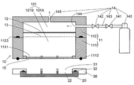
- the schematic block diagram which shows one Embodiment of the powder filling apparatus which concerns on this invention.
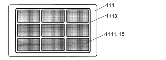
- the bottom view which shows the lower opening, grid member, and sealing material in the powder filling apparatus of this embodiment.
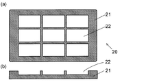
- the top view (a) and longitudinal cross-sectional view (b) which show an example of the filling object container with which the powder is filled with the powder filling apparatus of this embodiment.
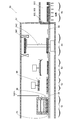
- Schematic which shows the whole structure of the sintered magnet manufacturing apparatus which concerns on a present Example.
- Embodiments of a powder filling apparatus, a sintered magnet manufacturing apparatus, and a sintered magnet manufacturing method according to the present invention will be described with reference to FIGS.
- the powder filling apparatus 10 includes a powder storage chamber 11, a film 12, a film lowering prevention member 13, and a pressure change applying unit 14, as shown in FIG.
- the powder storage chamber 11 includes a main body 111 and a lid 112.
- the main body 111 has a rectangular parallelepiped box shape, the entire ceiling is open, and a lower opening 1111 described later is provided at the bottom.
- the lid 112 has a rectangular parallelepiped box shape having the same cross section as that of the main body 111.
- the entire bottom portion is open, and a later-described air supply port 144 is provided on the side wall, and a later-described exhaust port is provided on the ceiling portion. 145 is provided.
- a sealing material 1123 is provided at the lower end of the side wall of the lid 112 over the entire circumference.
- a powder storage chamber 11 having an internal space 101 in which airtightness at the boundary of the lid 112 is ensured is configured.
- the sealing material 1123 may be provided on the upper end of the side wall of the main body 111.
- the lower opening 1111 has a substantially rectangular shape, and is provided in a total of nine, three in the long side direction and three in the short side direction of the cross section of the main body 111.
- a grid member 15 is attached to each lower opening 1111.
- the grid member 15 is formed by stretching a plurality of wires at regular intervals in the vertical and horizontal directions.
- the interval between the wires of the grid member 15 was set to 2 mm, with the powder having an average particle size of 3 ⁇ m being the target for filling the container to be filled.
- the spacing between the wires of the grid member 15 is three orders of magnitude larger than the average particle diameter of the powder. However, the powder particles are aggregated, so that the powder is simply placed on the grid member 15. It does not fall through the wires.
- a sealing material 1113 is provided on the lower surface of the lid 112 so as to surround the entire nine lower openings 1111 (FIG. 2).
- the membrane 12 is stretched below the air supply port 144 in the lid 112.
- the film 12 is made of silicone rubber having a film thickness of 0.5 mm, but the film thickness is not limited to this.
- the membrane 12 may be made of other materials such as urethane rubber and nitrile rubber as long as it has flexibility. With this film 12, the internal space 101 of the powder storage chamber 11 is separated into an upper space 101 ⁇ / b> A above the film 12 and a lower space 101 ⁇ / b> B below the film 12.
- the film lowering prevention member 13 is provided below the film 12 in the lid 112 and separated from the film 12.
- a stainless steel plate material in which holes having a diameter of 3 mm for allowing gas to pass is provided at intervals of 5 mm vertically and horizontally is used as the film lowering prevention member 13.
- the size and shape of the holes, the interval at which the holes are arranged, or the material of the plate material is not limited to this.
- the film lowering prevention member 13 is a net made of wire made of stainless steel or other materials, a plurality of bars made of the same material arranged in the horizontal direction, or one wire or bar. You may use what was handed over only in the horizontal direction.
- the pressure change applying unit 14 includes a high-pressure gas cylinder 140, a first valve 141, a second valve 142, a temporary storage pipe 143, an air supply port 144, and an exhaust port 145.
- the high pressure gas cylinder 140 is connected to the first valve 141, the first valve 141 and the second valve 142 are connected by a temporary storage pipe 143, and the second valve 142 is connected to the air supply port 144.
- the exhaust port 145 has a smaller diameter than the air supply port 144 and is always open to the space outside the powder storage chamber 11.
- an inert gas is used as the gas supplied from the high-pressure gas cylinder 140 for the following reason. Nitrogen gas or rare gas can be used as the inert gas.
- the powder filling device 10 is inert inside the portion of the powder filling device 10 excluding at least the high-pressure gas cylinder 140, the first valve 141, the second valve 142, and the temporary storage pipe 143. It is accommodated in an outer container (not shown) filled with gas (made oxygen-free).
- an exhaust pipe for discharging the gas discharged from the exhaust port 145 to the outside of the outer container may be provided, but if an inert gas is used as the gas supplied from the high-pressure gas cylinder 140 as described above, The gas can be discharged from the exhaust port 145 into the outer container, and the exhaust pipe can be omitted.
- the gas supplied from the high-pressure gas cylinder 140 does not come into contact with the powder, so that air can be used even when handling easily oxidizable powder.
- the powder filling apparatus 10 has a moving mechanism (not shown) of the lid 112 in order to move the lid 112 laterally from a position immediately above the body 111 when supplying the powder into the body 111. is doing.
- the filling target container 20 includes a flat plate-like cavity (powder filling portion) 22 on the upper surface side of a rectangular flat plate-like main body 21 and is long at the same interval as the lower opening 1111 of the powder filling device 10. There are nine in total, 3 in the side direction and 3 in the short side direction.
- the upper surface of the cavity 22 has the same shape as the lower opening 1111.
- the number and position of the cavities 22 are arbitrary, and the lower opening 1111 may be provided in the main body 111 of the powder filling apparatus 10 according to the number and position.
- the spacer 30 shown in FIG. 1 is used.
- the spacer 30 has nine through-holes 31 provided in a plate material in the same shape and in the same arrangement as the lower opening 1111, and a sealing material 32 provided on the lower surface so as to surround the entire nine through-holes 31. It is.
- the powder filling apparatus 10 of the present embodiment will be described with reference to FIG. First, in a state where the main body 111 and the lid 112 are separated, the powder P is supplied into the main body 111 (a). At this time, the powder P is placed on the grid member 15 provided in the lower opening 1111, but does not fall between the wires of the grid member 15 for the reason described above.
- the filling target container 20 with the spacer 30 mounted on the upper surface is arranged directly below the main body 111 so that the position of the lower opening 1111 of the main body 111 and the cavity 22 of the filling target container 20 are aligned.
- the lid 112 is placed on the main body 111.
- the powder storage chamber 11 is formed by pushing the lid 112 downward with a pressing device (not shown) (b).
- a pressing device not shown
- airtightness is ensured by the sealing materials 1123, 1113, and 32 between the lid 112 and the main body 111, between the main body 111 and the spacer 30, and between the spacer 30 and the filling target container 20, respectively.
- the pressure in the upper space 101A of the powder storage chamber 11 is repeatedly increased and decreased by the following method (c).
- the exhaust port 145 is always open, the diameter is smaller than that of the air supply port 144, so that the gas in the upper space 101A is gradually discharged from the exhaust port 145. Therefore, the pressure in the upper space 101A increases rapidly when the second valve 142 is opened, and then gradually decreases.
- the operation so far is set as one cycle and repeated several tens of times per second.
- the amount of the high-pressure gas introduced into the upper space 101A in one cycle can be made constant.
- the ratio (duty ratio) of the pressure of the compressed gas, the period, and the time during which the compressed gas is supplied in one period may be appropriately determined by a person skilled in the art through preliminary experiments for each powder to be handled.
- the membrane 12 vibrates by repeatedly raising and lowering the pressure in the upper space 101A in this way.
- the pressure in the lower space 101B of the powder storage chamber 11 also repeatedly increases and decreases.
- the upper surface of the powder P in the powder storage chamber 11 is pushed by the gas in the lower space 101 ⁇ / b> B, and is pushed into the cavity 22 of the container 20 to be filled through between the wires of the grid member 15.
- the film 12 is provided between the air supply port 144 and the exhaust port 145 and the powder P in the powder storage chamber 11, the air supply port 144 is formed even if the powder P rises due to the fluctuation of the pressure in the lower space 101B. And the exhaust port 145 is not clogged.
- membrane fall prevention member 13 is provided apart from the film
- the filling density in the cavity 22 of the container 20 to be filled can be made uniform, and the grid member 15 can be prevented from being clogged.
- the operation of increasing and decreasing the pressure is performed for a predetermined time, whereby the inside of the cavity 22 and the through hole 31 of the spacer 30 on the cavity 22 are filled with the powder P. After that, the filling target container 20 and the spacer 30 are kept apart from the main body 111 (d). Thus, the operation for filling the cavity 22 and the through hole 31 with the powder P is completed.
- the powder filling apparatus 10 (with the film 12 left) except for the film lowering prevention member 13 (Comparative Example 1) and the powder filling apparatus 10 from which the film 12 and the film lowering prevention member 13 are removed
- Comparative Example 2 A similar experiment was conducted for (Comparative Example 2). The experiment was performed on 20 filling target containers 20 in the example and the comparative example 1, and 3 filling target containers 20 in the comparative example 2. At that time, after filling one filling target container 20 with powder, the operation is repeated to remove the filling target container 20 from the lower part of the main body 111 and then attach the next filling target container 20 to fill the powder. It was.
- the difference between the maximum value and the minimum value of Comparative Example 2 is slightly larger than that of the other examples, but no significant difference is found between the Examples and Comparative Examples 1 and 2 other than that. This is considered to be because the number of times of contact between the powder in the powder storage chamber 11 and the film 12 is still small.
- Example and Comparative Example 2 In the second and third times, in Example and Comparative Example 1, almost no change from the first was observed, whereas in Comparative Example 2, the average value of the filling amount decreased and the maximum value as the number of times passed. And the difference between the minimum values (variation for each cavity 22) increased. This is presumably because, in Comparative Example 2, the air supply port 144 and the exhaust port 145 were clogged due to the absence of the film 12, and it was difficult to transmit the pressure change to the powder.
- the example can be more uniformly and densely filled with the powder than the comparative examples 1 and 2.
- the sintered magnet manufacturing apparatus 50 of the present embodiment includes a powder filling device (powder filling unit) 10, a powder densification device 52, a lid mounting unit 53, an orientation device (the orientation unit) 54, and sintering.
- a furnace (the sintered part) 55 is included.
- the sintered magnet manufacturing apparatus 50 is a conveying apparatus (belt conveyor) that conveys the container 20 to be filled in the order of the powder filling apparatus 10, the powder densification apparatus 52, the lid mounting portion 53, the orientation apparatus 54, and the sintering furnace 55. 56.
- each device other than the sintering furnace 55 is housed in a common outer container 57 having an inert gas atmosphere inside, and an inert gas is separately supplied into the sintering furnace 55 as well.
- an inert gas atmosphere In an inert gas atmosphere.
- the above-described oxygen-free atmosphere housing portion is constituted by the components that make the inside of the outer container 57 and the sintering furnace 55 an inert gas atmosphere.
- the high-pressure gas cylinder 140, the first valve 141, the second valve 142, and the temporary storage pipe 143 are disposed outside the outer container 57.
- the powder filling device 10 is a device that fills the filling target container 20 with powder as a raw material of the sintered magnet, and has the configuration as described above.
- the powder densification apparatus 52 has the punch 35 described above.
- the lid attaching part 53 is an apparatus for attaching a lid of the filling target container 20 (different from the lid 112 of the powder filling apparatus 10) to the filling target container 20 filled with powder. This lid is used to prevent the alloy powder from scattering from the filling target container 20 due to a magnetic field in the orientation device 54, gas convection in the sintering furnace 55, or the like.
- the orientation device 54 includes a coil 541 and a container lifting device 542.
- the coil 541 has a substantially vertical (vertical) axis and is disposed above the container lifting device 542.
- the container lifting device 542 is a device that lifts and lowers the filling target container 20 that has been transported by the container transport device 56 between the container 541 and the inside of the coil 541.
- the sintering furnace 55 includes a sintering chamber 551 that accommodates a large number of containers 20 to be filled, a carry-in port 552 that communicates with the outer vessel 57, and a door 553 having heat insulation provided at the carry-in port 552.
- the container transport device 56 transports the filling target container 20 to the powder filling device 10, and the alloy powder is filled into the cavity 22 of the filling target container 20 as described above.
- the container 20 to be filled is transported to the powder densification device 52 by the container transport device 56, and the powder is densified using the punch 35 as described above.
- the container transport device 56 transports the filling target container 20 to the lid attaching portion 53, and the lid is attached to the filling target container 20.
- the filling target container 20 is transported to the aligning device 54 by the container transporting device 56, arranged in the coil 541 by the container lifting / lowering device 542 in the aligning device 54, and the powder in the filling target container 20 is generated by the magnetic field generated by the coil 541.
- the container 20 to be filled is lowered from the coil 541 by the container lifting / lowering device 542, transported to the sintering furnace 55 by the container transport device 56, and a predetermined temperature (usually 800) in the sintering chamber 551.
- the powder in the container 20 to be filled is sintered by heating to ⁇ 1100 ° C.
- the sintered magnet manufacturing apparatus 50 can manufacture a sintered magnet by the PLP method in which orientation and sintering are performed in a magnetic field without performing compression molding.
- the shape of the main body of the powder filling device is a rectangular parallelepiped in the above embodiment, but may be a cylindrical shape or other shapes.
- the shape of the lid of the powder filling device may be appropriately determined according to the shape of the main body.
- the diameter of the exhaust port of the powder filling device is smaller than the diameter of the air supply port in the embodiment, it may be the same as or larger than the diameter of the air supply port.
- the exhaust port is always open. However, a valve is provided at the exhaust port so that the valve is closed when the pressure in the powder storage chamber is increased, and the valve is opened when the pressure is decreased. You may make it do.
- the pressure in the powder storage chamber is changed periodically (that is, at regular time intervals) in the above-described embodiment, the pressure may be increased and decreased at irregular timings.
Landscapes
- Engineering & Computer Science (AREA)
- Mechanical Engineering (AREA)
- Manufacturing & Machinery (AREA)
- Power Engineering (AREA)
- Chemical & Material Sciences (AREA)
- Materials Engineering (AREA)
- Metallurgy (AREA)
- Organic Chemistry (AREA)
- Powder Metallurgy (AREA)
- Manufacturing Cores, Coils, And Magnets (AREA)
- Basic Packing Technique (AREA)
Abstract
L'invention concerne un dispositif de remplissage de poudre (10) comprenant : une chambre de stockage de poudre (11) ayant un espace interne pour stocker de la poudre et une ouverture inférieure (1111), au niveau de la portion inférieure, apte à former un espace scellé avec une partie de remplissage de poudre (cavité 22) d'un récipient à remplir (20) ; une membrane flexible (12) étirée dans la chambre de stockage de poudre (11) pour séparer de manière étanche à l'air des espaces sur le côté supérieur et le côté inférieur de la membrane ; une partie conférant un changement de pression (14) pour augmenter et abaisser de façon répétée la pression sur le côté supérieur de la membrane (12) dans la chambre de stockage de poudre (11) ; et un élément empêchant la chute de la membrane (13) situé espacé de et sous la membrane (12) dans la chambre de stockage de poudre (11) pour empêcher la membrane (12) de tomber plus bas qu'une position prédéfinie. La poudre peut être entrée dans un récipient à remplir, sans boucher un orifice d'alimentation en gaz ou un orifice d'évacuation de gaz avec de la poudre en suspension et à une densité de remplissage uniforme.
Applications Claiming Priority (2)
| Application Number | Priority Date | Filing Date | Title |
|---|---|---|---|
| JP2016-029302 | 2016-02-18 | ||
| JP2016029302A JP2017145477A (ja) | 2016-02-18 | 2016-02-18 | 粉末充填装置、焼結磁石製造装置、及び焼結磁石製造方法 |
Publications (1)
| Publication Number | Publication Date |
|---|---|
| WO2017141815A1 true WO2017141815A1 (fr) | 2017-08-24 |
Family
ID=59625176
Family Applications (1)
| Application Number | Title | Priority Date | Filing Date |
|---|---|---|---|
| PCT/JP2017/004767 Ceased WO2017141815A1 (fr) | 2016-02-18 | 2017-02-09 | Dispositif de remplissage de poudre, dispositif de fabrication d'aimant fritté et procédé de fabrication d'aimant fritté |
Country Status (2)
| Country | Link |
|---|---|
| JP (1) | JP2017145477A (fr) |
| WO (1) | WO2017141815A1 (fr) |
Cited By (1)
| Publication number | Priority date | Publication date | Assignee | Title |
|---|---|---|---|---|
| WO2025222429A1 (fr) * | 2024-04-25 | 2025-10-30 | 瑞声开泰科技(马鞍山)有限公司 | Matrice et procédé de fabrication d'acier magnétique profilé |
Citations (3)
| Publication number | Priority date | Publication date | Assignee | Title |
|---|---|---|---|---|
| JPH1149101A (ja) * | 1997-08-07 | 1999-02-23 | Inter Metallics Kk | 充填方法及びその装置 |
| JP2001334398A (ja) * | 2000-05-26 | 2001-12-04 | Hitachi Powdered Metals Co Ltd | 粉末成形プレスにおける粉末充填方法と給粉装置 |
| WO2014119778A1 (fr) * | 2013-02-04 | 2014-08-07 | インターメタリックス株式会社 | Dispositif de remplissage de poudre |
-
2016
- 2016-02-18 JP JP2016029302A patent/JP2017145477A/ja active Pending
-
2017
- 2017-02-09 WO PCT/JP2017/004767 patent/WO2017141815A1/fr not_active Ceased
Patent Citations (3)
| Publication number | Priority date | Publication date | Assignee | Title |
|---|---|---|---|---|
| JPH1149101A (ja) * | 1997-08-07 | 1999-02-23 | Inter Metallics Kk | 充填方法及びその装置 |
| JP2001334398A (ja) * | 2000-05-26 | 2001-12-04 | Hitachi Powdered Metals Co Ltd | 粉末成形プレスにおける粉末充填方法と給粉装置 |
| WO2014119778A1 (fr) * | 2013-02-04 | 2014-08-07 | インターメタリックス株式会社 | Dispositif de remplissage de poudre |
Cited By (1)
| Publication number | Priority date | Publication date | Assignee | Title |
|---|---|---|---|---|
| WO2025222429A1 (fr) * | 2024-04-25 | 2025-10-30 | 瑞声开泰科技(马鞍山)有限公司 | Matrice et procédé de fabrication d'acier magnétique profilé |
Also Published As
| Publication number | Publication date |
|---|---|
| JP2017145477A (ja) | 2017-08-24 |
Similar Documents
| Publication | Publication Date | Title |
|---|---|---|
| CN104981404B (zh) | 粉末填充装置及烧结磁铁制造装置 | |
| JP6280137B2 (ja) | 希土類焼結磁石の製造方法及び当該製法にて使用される製造装置 | |
| KR101735144B1 (ko) | NdFeB계 소결자석 제조장치 | |
| JP5475325B2 (ja) | 焼結磁石製造装置 | |
| WO2017141815A1 (fr) | Dispositif de remplissage de poudre, dispositif de fabrication d'aimant fritté et procédé de fabrication d'aimant fritté | |
| JP6834249B2 (ja) | 粉末充填装置及び焼結磁石製造装置 | |
| CN107088656B (zh) | 粉末填充装置、烧结磁体制造设备和烧结磁体制造方法 | |
| EP2955731B1 (fr) | Dispositif de production d'aimant fritté et procédé de production d'aimant fritté | |
| JP6848544B2 (ja) | 粉末充填装置、焼結磁石製造装置及び焼結磁石製造方法 | |
| CN110871271B (zh) | 粉末填充装置、烧结磁体制造装置以及烧结磁体制造方法 |
Legal Events
| Date | Code | Title | Description |
|---|---|---|---|
| 121 | Ep: the epo has been informed by wipo that ep was designated in this application |
Ref document number: 17753073 Country of ref document: EP Kind code of ref document: A1 |
|
| NENP | Non-entry into the national phase |
Ref country code: DE |
|
| 122 | Ep: pct application non-entry in european phase |
Ref document number: 17753073 Country of ref document: EP Kind code of ref document: A1 |