WO2017145190A1 - Steam turbine - Google Patents
Steam turbine Download PDFInfo
- Publication number
- WO2017145190A1 WO2017145190A1 PCT/JP2016/000945 JP2016000945W WO2017145190A1 WO 2017145190 A1 WO2017145190 A1 WO 2017145190A1 JP 2016000945 W JP2016000945 W JP 2016000945W WO 2017145190 A1 WO2017145190 A1 WO 2017145190A1
- Authority
- WO
- WIPO (PCT)
- Prior art keywords
- support
- exchanger
- partition
- steam turbine
- turbine according
- Prior art date
- Legal status (The legal status is an assumption and is not a legal conclusion. Google has not performed a legal analysis and makes no representation as to the accuracy of the status listed.)
- Ceased
Links
Images


Classifications
-
- F—MECHANICAL ENGINEERING; LIGHTING; HEATING; WEAPONS; BLASTING
- F01—MACHINES OR ENGINES IN GENERAL; ENGINE PLANTS IN GENERAL; STEAM ENGINES
- F01D—NON-POSITIVE DISPLACEMENT MACHINES OR ENGINES, e.g. STEAM TURBINES
- F01D25/00—Component parts, details, or accessories, not provided for in, or of interest apart from, other groups
- F01D25/24—Casings; Casing parts, e.g. diaphragms, casing fastenings
- F01D25/246—Fastening of diaphragms or stator-rings
-
- F—MECHANICAL ENGINEERING; LIGHTING; HEATING; WEAPONS; BLASTING
- F01—MACHINES OR ENGINES IN GENERAL; ENGINE PLANTS IN GENERAL; STEAM ENGINES
- F01D—NON-POSITIVE DISPLACEMENT MACHINES OR ENGINES, e.g. STEAM TURBINES
- F01D9/00—Stators
- F01D9/02—Nozzles; Nozzle boxes; Stator blades; Guide conduits, e.g. individual nozzles
- F01D9/04—Nozzles; Nozzle boxes; Stator blades; Guide conduits, e.g. individual nozzles forming ring or sector
- F01D9/042—Nozzles; Nozzle boxes; Stator blades; Guide conduits, e.g. individual nozzles forming ring or sector fixing blades to stators
-
- F—MECHANICAL ENGINEERING; LIGHTING; HEATING; WEAPONS; BLASTING
- F01—MACHINES OR ENGINES IN GENERAL; ENGINE PLANTS IN GENERAL; STEAM ENGINES
- F01D—NON-POSITIVE DISPLACEMENT MACHINES OR ENGINES, e.g. STEAM TURBINES
- F01D25/00—Component parts, details, or accessories, not provided for in, or of interest apart from, other groups
- F01D25/24—Casings; Casing parts, e.g. diaphragms, casing fastenings
-
- F—MECHANICAL ENGINEERING; LIGHTING; HEATING; WEAPONS; BLASTING
- F05—INDEXING SCHEMES RELATING TO ENGINES OR PUMPS IN VARIOUS SUBCLASSES OF CLASSES F01-F04
- F05D—INDEXING SCHEME FOR ASPECTS RELATING TO NON-POSITIVE-DISPLACEMENT MACHINES OR ENGINES, GAS-TURBINES OR JET-PROPULSION PLANTS
- F05D2220/00—Application
- F05D2220/30—Application in turbines
- F05D2220/31—Application in turbines in steam turbines
-
- F—MECHANICAL ENGINEERING; LIGHTING; HEATING; WEAPONS; BLASTING
- F05—INDEXING SCHEMES RELATING TO ENGINES OR PUMPS IN VARIOUS SUBCLASSES OF CLASSES F01-F04
- F05D—INDEXING SCHEME FOR ASPECTS RELATING TO NON-POSITIVE-DISPLACEMENT MACHINES OR ENGINES, GAS-TURBINES OR JET-PROPULSION PLANTS
- F05D2230/00—Manufacture
- F05D2230/80—Repairing, retrofitting or upgrading methods
-
- F—MECHANICAL ENGINEERING; LIGHTING; HEATING; WEAPONS; BLASTING
- F05—INDEXING SCHEMES RELATING TO ENGINES OR PUMPS IN VARIOUS SUBCLASSES OF CLASSES F01-F04
- F05D—INDEXING SCHEME FOR ASPECTS RELATING TO NON-POSITIVE-DISPLACEMENT MACHINES OR ENGINES, GAS-TURBINES OR JET-PROPULSION PLANTS
- F05D2260/00—Function
- F05D2260/30—Retaining components in desired mutual position
- F05D2260/31—Retaining bolts or nuts
Definitions
- the present invention relates to a stationary component of a steam turbine.
- a stationary blade which is a main component of a stationary component provided inside the steam turbine, is fixed to a casing surrounding the casing of the steam turbine via a partition plate.
- the steam turbine's stationary components for example, the partition water droplets, impinge on the steam at high speed, causing a phenomenon that the surface is scraped off (erosion).
- a phenomenon occurs in which steam enters the crack and corrodes the stationary part (corrosion). Therefore, maintenance / inspection work for periodically replacing stationary parts such as a partition plate is performed before a failure due to erosion or corrosion occurs, but the work load is large.
- Patent Document 1 an erosion countermeasure has been proposed in which a weld overlay of stainless steel is formed at a place where erosion is likely to occur or a Ni-based alloy is plasma sprayed. Thereby, the work burden can be reduced by extending the period for exchanging stationary parts.
- an object of the present invention is to provide a steam turbine including a stationary component of a steam turbine that can be easily replaced when erosion occurs.
- the steam turbine of the present invention includes a stationary blade provided in a casing inside a casing in which steam flows from the upstream side toward the downstream side, and support means for supporting the stationary blade on the casing.
- the support means includes a first support that is fixed to the casing, a second support that connects the stationary blade and the first support, and the first support and the first support on the upstream side with reference to the direction in which the steam flows.
- An exchange body provided detachably between the two supports is provided.
- the exchanger can be provided between the first support and the second support that are likely to cause erosion, the exchanger that has undergone erosion at a necessary time is used as a new exchanger. Can be exchanged.
- the exchange body since the exchange body is detachable, it can be easily exchanged for a new exchange body without moving to a place where special devices are provided.
- the exchanger in the present invention is preferably composed of a material having higher erosion resistance than both the first support and the second support. Thereby, the period until it replaces
- the exchange body in this invention can be provided in the accommodation area
- the exchange body in the present invention preferably has an inlay structure in which the insertion end is inserted into the holding groove formed in the second support body in the accommodation region. Accordingly, it is easy to position the exchange body at a required position, and it is easy to maintain the posture of the exchange body during the exchange work.
- the exchange body in this invention is supported by the 2nd support body by the suppression body attached to a 2nd support body so that attachment or detachment is possible. Thereby, the support to the 2nd support of an exchange body can be performed more reliably.
- One or both of the exchange body and the suppression body in the present invention can be detachably attached by the fastening means. Accordingly, one or both of the exchange body and the deterrent body can be attached and detached, and the attachment of the exchange body to the second support body and the attachment of the first support body of the deterrent body can be performed easily and reliably. It can be carried out.
- the connecting portion between the first support and the second support has a structure in which the first support is inserted into a recess provided in the second support. In this case, it can be detachably provided between the first support and the second support. Thereby, the exchanger can be supported also by the first support.
- the 2nd support body in this invention can be equipped with the upstream partition which divides a dent from an upstream, the downstream partition which divides a dent from a downstream, and the bottom floor which divides a dent from radial direction.
- the exchange body is detachably attached to the second support body by the restraining body detachably attached to the second support body.
- the deterrent body includes a fixed side fixed to the second support body, and a deterrent side that is connected to the fixed side and presses the exchange body against the upstream partition. Thereby, an exchange body is supported more reliably with respect to a 2nd support body.
- the 2nd support body in this invention can be integrally equipped with the flow guide which guides the flow to the downstream of a vapor
- connection between the first support and the second support is preferably performed by a fastening means between the downstream partition of the second support and the first support.
- the exchange body can be provided between the first support body and the second support body where erosion is likely to occur. Therefore, the exchange body in which erosion has occurred can be replaced with a new exchange body when necessary. Moreover, according to the present invention, since the exchange body is detachable, it can be easily exchanged for a new exchange body without moving to a place where special devices are provided.
- FIG. 2 is a partially enlarged view of FIG. 1.
- FIG. 3 is a partially enlarged view of FIG. 2.
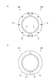
- (A) is a top view of two exchange bodies,
- (b) is a top view of two suppression bodies.
- the stationary component 1 of a steam turbine 90 As shown in FIG. 1, the stationary component 1 of the present invention is installed inside a steam turbine 90.
- the steam turbine 90 includes a casing 91, a casing 92 hermetically sealed by the casing 91, an adjustment valve 93 that adjusts the amount and pressure of the steam S flowing into the casing 92,
- a turbine rotor 95 is provided inside the casing 91 so as to be rotatable around a rotation axis C, and transmits power to a machine such as a generator (not shown), and a plurality of bearing portions that support the turbine rotor 95 so as to be rotatable around the axis.
- the interior of the passenger compartment 92 is formed such that the steam S flows from the upstream U to the downstream L.
- the pressure of the upstream side U is relatively higher than that of the downstream side L, and the steam S becomes lower in pressure as it flows to the downstream side L.
- the direction orthogonal to the direction of the rotation axis C of the turbine rotor 95 is referred to as the radial direction
- the side close to the radial rotation axis C is the inner side in the radial direction
- the side far from the radial rotation axis C. Is called the outside in the radial direction.
- the upstream side U and the downstream side L of the flow of the steam S used in the present embodiment show a relative positional relationship.
- the turbine rotor 95 housed in the passenger compartment 92 includes a shaft 96 and a moving blade 97 that is detachably provided on the outer peripheral surface of the shaft 96.
- a plurality of moving blades 97 are provided at a predetermined interval from the upstream U to the downstream L, thereby forming a moving blade group.
- Each rotor blade 97 is formed continuously around the shaft 96 by attaching a half segment to the shaft 96.
- a stationary blade 10 extending from the inner peripheral surface side of the casing 91 toward the central axis C of the shaft 96 is provided in the vehicle interior 92. Similar to the moving blades 97, a plurality of stationary blades 10 are provided from the upstream U to the downstream L at a predetermined interval to constitute a stationary blade group. The respective stationary blades 10 are arranged alternately with the moving blades 97 by being arranged on the upstream side U of the moving blades 97 constituting the moving blade group.
- the stationary blade 10 is a constituent element of the stationary component 1, but in this embodiment, the exchanger 30 described later is applied to the two stationary blades 10 on the downstream side L among the plurality of stationary blades 10.
- the stationary component 1 is a means for supporting the stationary blade 10 in addition to the stationary blade 10 described above.
- a support 50 a support 50.
- the second stationary component 1 from the downstream side L will be described as an example.
- Partition body 20 The partition body 20 is provided to ensure that the steam S from the upstream side U flows to the downstream side L via the moving blade 97.
- the partition 20 is provided continuously to the inner peripheral surface of the casing 91.
- the partition 20 is configured by a combination of two segments 20 ⁇ / b> A and 20 ⁇ / b> B having a halved shape.
- the main body 21 of the partition 20 has a recess 22 as a storage area for storing a part of the support 50.
- an upstream partition 28 that partitions the recess 22 from the upstream side U
- a downstream partition 29 that partitions the recess 22 from the downstream side L
- a bottom floor 23 that partitions the recess 22 from the radial direction.
- the depression 22, the bottom floor 23, the upstream partition 28, and the downstream partition 29 are continuous in the circumferential direction.
- the connection part of the partition 20 and the support body 50 has an inlay structure.
- the hatching of the exchanger 30 is omitted.
- the bottom floor 23 is formed in parallel to the rotation axis C.
- the bottom floor 23 includes a holding groove 25 as a part of the upstream side U is retracted radially inward from the other regions.
- the recess 22 accommodates the exchange body 30 in an area corresponding to the holding groove 25, and accommodates a part of the front end side of the support body 50 on the downstream side L from this area.
- the illustration of the partition 20 is omitted in FIG. 3, a necessary gap is provided between the bottom floor 23 and the tip of the support body 50 in consideration of thermal expansion during the operation of the steam turbine 90. Yes.
- the upstream partition 28 supports an exchange 30 described later from a side surface 28A facing the recess 22.
- the upstream partition 28 has a dimension that protrudes radially outward from the bottom floor 23 as compared with the downstream partition 29, and its height exceeds half of the support 50 in the radial direction. By setting the height in this way, the partition 20 ensures a region overlapping with the support 50 in the radial direction and ensures support to the rotation axis C.
- the flow guide 27 is integrally provided with the main body 21 by reducing the inner diameter in the radial direction.
- the flow guide 27 guides the flow of steam downstream, and is disposed so as to face the tip of the corresponding moving blade 97.
- the exchange body 30 corresponding to the second support body of the present invention is a member that substitutes for a portion where the erosion is likely to occur in the partition body 20, and with the partition body 20 on the upstream side based on the direction in which the steam S flows. By being detachably provided on the partition 20 between the supports 50, replacement work at the time of maintenance and inspection is facilitated.
- the exchange body 30 is formed in an annular shape so as to be continuous in the circumferential direction of the vehicle interior 92.
- the exchange body 30 is configured by a combination of two segments 30A and 30B having a halved shape for the convenience of being arranged around the partition body 20.
- the exchange body 30 has a rectangular cross section, and the height H from the bottom floor 23 when the partition body 20 is disposed at a predetermined position is the height of the upstream partition 28. Match the height. That is, the outer diameter surface of the upstream partition 28 and the outer diameter surface of the exchanger 30 are flush with each other, and there is no step between them, so that the scale that causes erosion and corrosion is retained. Can be reduced.
- the exchanger 30 has a certain thickness (dimension in the direction of the rotation axis C) from the outer peripheral side toward the inner peripheral side, and the insertion end 31 whose innermost peripheral side is thinned, And an opposed outer diameter surface 32. The thickness and height (diameter dimension) of the insertion end 31 are set so that the insertion end 31 is inserted into the holding groove 25 without a gap.
- the exchange body 30 is fixed to the partition body 20 by bolts B1.
- the bolt B ⁇ b> 1 passes through the bolt hole 33 formed in the exchange body 30 and is fastened to the partition body 20.
- the bolt B1 is inserted to a predetermined position for fixing the exchange body 30 to the partition body 20, the bolt B1 is placed so that its head is accommodated in the exchange body 30 and only the tip surface thereof is exposed from the exchange body 30.
- the dimension of the bolt hole 33 is set.
- the bolt B1 can be a hexagon socket bolt. The same applies to the bolt B2.
- fastening with a plurality of bolts B ⁇ b> 1 and bolt holes 33 at equal intervals in the circumferential direction contributes to improving the adhesion between the exchange body 30 and the partition body 20. Thereby, it is possible to prevent the steam S from flowing between the exchanger 30 and the partition body 20.
- interval of fastening may not be uniform.
- the outer diameter surface 32 is exposed in the vehicle interior 92.
- the exposed outer diameter surface 32 collides with water droplets flowing from the upstream U in the passenger compartment 92 in the stationary component 1 and accumulates the collided water droplets.
- the exchange body 30 is formed of a material having higher wear resistance than both the partition body 20 and the support body 50, that is, a material having high erosion resistance. As a result, a part of the wear-resistant exchanger 30 is exposed at a location where erosion is likely to occur, and erosion can be effectively prevented from occurring.
- the restraining body 40 fixes the exchange body 30 to the partition body 20.
- the suppressing body 40 is formed in an annular shape so as to be continuous in the circumferential direction of the casing 91.
- the restraining body 40 is configured by a combination of two segments 40A and 40B having a halved shape for convenience of arrangement around the partition body 20.
- the restraining body 40 has an L-shaped cross section, and a restraining side 43 that fixes the restraining body 40 to the partition body 20 and a restraint that presses the replacement body 30 toward the partition body 20. Side 45.
- the restraining side 45 covers a part of the head of the bolt B1 that fixes the exchanger 30. Thereby, it is possible to prevent the bolt B1 fastening the exchanger 30 from falling off.
- the suppression body 45 presses the replacement body 30 toward the upstream partition 28 of the partition 20.
- the support of the exchange body 30 with respect to the partition body 20 can be made more reliable.
- the surface of the restraining side 45 and the fixed side 43 that is in contact with the support body 50 has a very small gap between the restraining body 40 and the support body 50 when the restraint body 40 is inserted into the holding groove 51 of the support body 50. It is formed to be a gap.
- the restraint body 40 of this embodiment has an L-shaped cross section, it can have the fixed side 43 and the restraint side 45 with a minimum cross-sectional area, in other words, a small amount of material. .
- a fixed side 43 is fastened to the partition body 20 by a bolt B ⁇ b> 2, and therefore, a bolt hole 41 penetrating the front and back of the fixed side 43 is provided in communication with the support body 50.
- the dimensions of the bolt B ⁇ b> 1 and the bolt hole 41 are set so that the head of the bolt B ⁇ b> 2 that has been fastened is accommodated inside the fixed side 43 and only the tip surface is exposed from the fixed side 43. By doing so, the clearance gap between the support body 50 and the bottom floor 23 of the partition 20 can be suppressed to the minimum.
- the deterrent body 40 may be formed of the same material as the exchanger 30 or may be formed of a different material, but is preferably formed of a material having high corrosion resistance.
- the support body 50 supports the stationary blade 10 via the partition body 20.
- the support body 50 corresponding to the first support body of the present invention extends from the inner peripheral surface of the casing 91 toward the central axis of the turbine rotor 95 and is formed in a semicircular shape that is continuous in the circumferential direction of the casing 91. ing.
- a holding groove 51 into which the restraining body 40 is inserted is formed on the side surface of the upstream side U of the support body 50.
- the support body 50 has an outer diameter surface side fixed to the inner peripheral surface of the casing 91 by welding or other means, and the partition body 20 is fixed to the inner diameter surface side.
- the support body 50 also has an annular shape, but is configured by combining two halved members.
- the support body 50 supports the partition body 20 by accommodating the inner diameter side of the support body 50 in the recess 22 of the partition body 20.
- the stationary component 1 including the partition body 20, the exchange body 30, the suppression body 40, and the support body 50 described above has the inner diameter side of the support body 50 accommodated in the recess 22 of the partition body 20, and the partition body 20 is the support body. 50.
- the exchange body 30 is fixed to the partition body 20 by fastening the restraining body 40 fixed to the partition body 20 and the bolt B1 to the partition body 20.
- the suppression body 40 is not exposed to the outside by being interposed between the three members of the partition body 20, the exchange body 30, and the support body 50.
- this embodiment can remove the used exchange body 30 from the partition body 20 by removing the volt
- the moving blade 97 can be removed from the turbine rotor 95 prior to the work of separating the partition 20 and the support 50.
- a new exchanger 30 prepared separately is disposed at a predetermined position where the insertion end 31 is inserted into the holding groove 25 of the partition body 20.
- positioned exchange body 30 is fixed to the partition 20 with the volt
- the partition body 20 is fixed to the support body 50 in the reverse order of the removal work, and the replacement work of the replacement body 30 is completed.
- the exchanger 30 is detachably attached. Therefore, even if erosion occurs in the exchange body 30, it is only necessary to exchange the exchange body 30, and it is not necessary to replace the partition body 20 as a whole. Therefore, since the members to be replaced can be minimized, the cost of maintenance / inspection work can be suppressed at a low cost.
- the replacement work of the suppressor 40 is the same.
- the replacement body 30 can be replaced by attaching and detaching bolts. Therefore, the replacement body 30 can be replaced without moving to a special environment. Can be reduced.
- the exchange body 30 of the present embodiment has a rectangular cross section, but the form of the exchange body of the present invention is not limited to this. Since the exchanger of the present invention is provided corresponding to the erosion of the contact portion between the partition 20 and the support 50 on the upstream side U, as long as the exchanger is provided in the region, the form is Is optional. For example, an exchanger having an L-shaped cross section can be used.
- the insertion end 31 is inserted into the holding groove 25, but the present invention is not limited to this.
- the lower end of the exchanger 30 may simply be placed on the flat bottom floor 23.
- the exchanger 30 may be attached to the support body 50. Also in this case, the exchange body 30 is fixed to the support body 50 with a bolt. It is preferable that the bolt penetrates the exchanger 30 and is fastened to the support member 50 so that the head is accommodated in the exchanger 30 as in the above-described embodiment.
- the outer diameter surface (32) of the exchanger 30 thus attached is exposed in the vehicle interior 92. Even when the exchanger 30 is attached to the support 50, a groove into which the exchanger 30 is inserted may be formed on the side surface of the upstream partition 28.
- the portion of the deterrence side 45 of the deterrence body 40 can be lengthened to cover the tip of the support body 50. If it does so, while being able to suppress that erosion generate
- the shape of the cross section of the deterrent body 40 is not limited to the L shape, and the form thereof is arbitrary as long as it has the deterring part and the fixing part.
- the cross section may be a triangle or a rectangle.
- fastening by bolts B1 and B2 is adopted as means for attaching the exchange body 30 or the like, but other methods may be adopted as long as they are detachably attached.
- both the replacement body 30 and the restraining body 40 are detachably attached by fastening means using bolts, but only one of them may be attached by fastening means.
- the present invention is applied to the two stationary parts 1 on the downstream side L.
- the present invention is applied to one or more stationary parts 1 among the plurality of stationary parts 1. May be.
- a recess can be provided on the support 50 side, and a part to be inserted into the recess can be provided on the partition 20 side.
- Stator blade 10 Stator blade 20 Partition body 20A, 20B Segment 21 Main body 22 Recess 23 Bottom floor 25 Holding groove 27 Flow guide 28 Upstream partition 29 Downstream partition 30 Exchanger 30A, 30B Segment 31 Insertion end 32 Outer diameter surface 33 Bolt hole 40 Suppressing body 40A, 40B Segment 41 Bolt hole 43 Fixed side 45 Suppressing side 50 Support body 51 Holding groove 90 Steam turbine 91 Casing 92 Car compartment 93 Adjusting valve 95 Turbine rotor 97 Rotor blade 98 Bearing part
Landscapes
- Engineering & Computer Science (AREA)
- Mechanical Engineering (AREA)
- General Engineering & Computer Science (AREA)
- Turbine Rotor Nozzle Sealing (AREA)
Abstract
Description
本発明は、蒸気タービンの静止部品に関する。 The present invention relates to a stationary component of a steam turbine.
蒸気タービンの内部に設けられる静止部品の主たる構成要素である静翼は、蒸気タービンの車室を取り囲むケーシングに、仕切板を介して固定されている。 A stationary blade, which is a main component of a stationary component provided inside the steam turbine, is fixed to a casing surrounding the casing of the steam turbine via a partition plate.
蒸気タービンの静止部品、例えば仕切板には、運転中に、蒸気に含まれるドレン水滴が高速でぶつかるので、その表面を削り取る現象(エロージョン)が生じ、これを放置すると、静止部品としての機能を損なうおそれがある。
さらに、エロージョンにより静止部品の表面に亀裂が生じると、その亀裂に蒸気が浸入して、静止部品を腐食する現象(コロージョン)が生じる。
したがって、エロージョンやコロージョンによる障害が生じる前に、仕切板をはじめとする静止部品を定期的に交換する保守・点検作業が行われるが、その作業負担は大きい。
During operation, the steam turbine's stationary components, for example, the partition water droplets, impinge on the steam at high speed, causing a phenomenon that the surface is scraped off (erosion). There is a risk of damage.
Furthermore, when a crack is generated on the surface of a stationary part due to erosion, a phenomenon occurs in which steam enters the crack and corrodes the stationary part (corrosion).
Therefore, maintenance / inspection work for periodically replacing stationary parts such as a partition plate is performed before a failure due to erosion or corrosion occurs, but the work load is large.
そこで、特許文献1に記載のように、エロージョンの生じやすい箇所に、ステンレス鋼の溶接肉盛を形成させたり、Ni基合金をプラズマ溶射被覆させたりするエロージョン対策が提案されている。これにより、静止部品を交換する期間を延ばすことにより、作業負担を軽減することができる。 Therefore, as described in Patent Document 1, an erosion countermeasure has been proposed in which a weld overlay of stainless steel is formed at a place where erosion is likely to occur or a Ni-based alloy is plasma sprayed. Thereby, the work burden can be reduced by extending the period for exchanging stationary parts.
しかし、溶接肉盛、プラズマによる被膜のように耐エロージョン性の層を形成したとしても、蒸気タービンを長期間使用すれば、エロージョンの発生を抑えることはできないので、保守・点検作業を行う必要がある。ところが、エロージョンが発生した部分に耐エロージョン性の層を溶接肉盛又はプラズマ溶接により形成するには、当該部品を当該耐エロージョン性の層を形成するのに必要な装置を備える場所まで搬送する必要があるので、その作業負担は大きい。 However, even if an erosion-resistant layer such as a weld overlay or plasma coating is formed, erosion cannot be suppressed if the steam turbine is used for a long period of time, so maintenance and inspection work must be performed. is there. However, in order to form an erosion-resistant layer by welding or plasma welding in a portion where erosion has occurred, it is necessary to transport the part to a place equipped with an apparatus necessary for forming the erosion-resistant layer. Therefore, the work burden is large.
以上より本発明は、エロージョンが発生した際の交換が容易な蒸気タービンの静止部品を備える蒸気タービンを提供することを目的とする。 Accordingly, an object of the present invention is to provide a steam turbine including a stationary component of a steam turbine that can be easily replaced when erosion occurs.
本発明の蒸気タービンは、蒸気が上流側から下流側に向けて流れるケーシングの内部の車室に設けられる静翼と、静翼をケーシングに支持する支持手段と、を備える。
この支持手段は、ケーシングに固定される第一支持体と、静翼と第一支持体を接続する第二支持体と、蒸気の流れる向きを基準にして、上流側における第一支持体と第二支持体の間に、着脱可能に設けられる交換体と、を備える、ことを特徴とする。
本発明の蒸気タービンによれば、交換体をエロージョンの生じやすい第一支持体と第二支持体の間に設けることができるので、必要な時期にエロージョンが生じた交換体を新たな交換体に交換できる。しかも、本発明によれば、交換体が着脱可能であるから、格別な装置類が備えられた場所に移動することなく、新たな交換体に容易に交換できる。
The steam turbine of the present invention includes a stationary blade provided in a casing inside a casing in which steam flows from the upstream side toward the downstream side, and support means for supporting the stationary blade on the casing.
The support means includes a first support that is fixed to the casing, a second support that connects the stationary blade and the first support, and the first support and the first support on the upstream side with reference to the direction in which the steam flows. An exchange body provided detachably between the two supports is provided.
According to the steam turbine of the present invention, since the exchanger can be provided between the first support and the second support that are likely to cause erosion, the exchanger that has undergone erosion at a necessary time is used as a new exchanger. Can be exchanged. Moreover, according to the present invention, since the exchange body is detachable, it can be easily exchanged for a new exchange body without moving to a place where special devices are provided.
本発明における交換体は、第一支持体と第二支持体の双方よりも耐エロージョン性の高い素材で構成されることが好ましい。
これにより、交換体を新しいものに交換するまでの期間を延ばし、交換頻度を少なくできる。
The exchanger in the present invention is preferably composed of a material having higher erosion resistance than both the first support and the second support.
Thereby, the period until it replaces | exchanges a replacement | exchange body for a new thing can be extended, and replacement | exchange frequency can be decreased.
本発明における交換体は、第二支持体に設けられる収容領域に着脱可能に設けることができる。
これにより、交換体を第一支持体と第二支持体の間に設置する作業の際に、所望の位置に容易に配置させることができる。
The exchange body in this invention can be provided in the accommodation area | region provided in a 2nd support body so that attachment or detachment is possible.
Thereby, in the operation | work which installs an exchange body between a 1st support body and a 2nd support body, it can be easily arrange | positioned in a desired position.
本発明における交換体は、収容領域において、第二支持体に形成された保持溝に、挿入端が挿入されるインロー構造をなしていることが好ましい。
これにより、交換体を必要な位置に位置決めするのが容易であるとともに、交換作業をする際に交換体の姿勢を維持しやすい。
The exchange body in the present invention preferably has an inlay structure in which the insertion end is inserted into the holding groove formed in the second support body in the accommodation region.
Accordingly, it is easy to position the exchange body at a required position, and it is easy to maintain the posture of the exchange body during the exchange work.
本発明における交換体は、第二支持体に着脱可能に取り付けられる抑止体により第二支持体に支持されることが好ましい。
これにより、交換体の第二支持体への支持をより確実に行うことができる。
It is preferable that the exchange body in this invention is supported by the 2nd support body by the suppression body attached to a 2nd support body so that attachment or detachment is possible.
Thereby, the support to the 2nd support of an exchange body can be performed more reliably.
本発明における交換体、及び、抑止体の一方又は双方は、締結手段により、着脱可能に取り付けることができる。
これにより、交換体、及び、抑止体の一方又は双方が、着脱可能であるとともに、交換体の第二支持体への取り付け、及び、抑止体の第一支持体の取り付け、を簡易かつ確実に行うことができる。
One or both of the exchange body and the suppression body in the present invention can be detachably attached by the fastening means.
Accordingly, one or both of the exchange body and the deterrent body can be attached and detached, and the attachment of the exchange body to the second support body and the attachment of the first support body of the deterrent body can be performed easily and reliably. It can be carried out.
本発明における第一支持体と第二支持体の接続部分は、第一支持体が第二支持体に設けられる窪みに挿入される構造をなしている場合には、交換体を、窪みの内部において、第一支持体と第二支持体の間に、着脱可能に設けることができる。
これにより、交換体を、第一支持体によっても支持することができる。
In the present invention, the connecting portion between the first support and the second support has a structure in which the first support is inserted into a recess provided in the second support. In this case, it can be detachably provided between the first support and the second support.
Thereby, the exchanger can be supported also by the first support.
本発明における第二支持体は、上流側から窪みを区画する上流衝立と、下流側から窪みを区画する下流衝立と、径方向から窪みを区画する底床と、を備えることができる。この場合には、交換体は、第二支持体に着脱可能に取り付けられる抑止体により第二支持体に着脱可能に取り付けられる。また、抑止体は、第二支持体に固定される固定辺と、固定辺に連なり、交換体を上流衝立に押し付ける抑止辺と、を備える。
これにより、交換体は、第二支持体に対してより確実に支持される。
The 2nd support body in this invention can be equipped with the upstream partition which divides a dent from an upstream, the downstream partition which divides a dent from a downstream, and the bottom floor which divides a dent from radial direction. In this case, the exchange body is detachably attached to the second support body by the restraining body detachably attached to the second support body. The deterrent body includes a fixed side fixed to the second support body, and a deterrent side that is connected to the fixed side and presses the exchange body against the upstream partition.
Thereby, an exchange body is supported more reliably with respect to a 2nd support body.
本発明における第二支持体は、下流衝立の一部に、蒸気の下流側への流れを案内するフローガイドを一体的に備えることができる。
これにより、フローガイドを個別に設けるのに比べて、製作コストを低減できる。
The 2nd support body in this invention can be integrally equipped with the flow guide which guides the flow to the downstream of a vapor | steam in a part of downstream partition.
Thereby, compared with providing a flow guide separately, manufacturing cost can be reduced.
本発明において、第一支持体と第二支持体の接続は、第二支持体の下流衝立と第一支持体の間の締結手段によることが好ましい。
そうすることにより、交換体の交換を含む保守・点検作業の負担を軽減できる。
In the present invention, the connection between the first support and the second support is preferably performed by a fastening means between the downstream partition of the second support and the first support.
By doing so, the burden of maintenance / inspection work including replacement of the exchanger can be reduced.
本発明によれば、交換体をエロージョンの生じやすい第一支持体と第二支持体の間に設けることができるので、必要な時期にエロージョンが生じた交換体を新たな交換体に交換できる。しかも、本発明によれば、交換体が着脱可能であるから、格別な装置類が備えられた場所に移動することなく、新たな交換体に容易に交換できる。 According to the present invention, the exchange body can be provided between the first support body and the second support body where erosion is likely to occur. Therefore, the exchange body in which erosion has occurred can be replaced with a new exchange body when necessary. Moreover, according to the present invention, since the exchange body is detachable, it can be easily exchanged for a new exchange body without moving to a place where special devices are provided.
以下、添付図面を参照しながら、本発明に係る蒸気タービン90の静止部品1の一実施形態について説明する。本発明の静止部品1は、図1に示すように、蒸気タービン90の内部に設置されている。
Hereinafter, an embodiment of a stationary component 1 of a
図1に示すように、蒸気タービン90は、ケーシング91と、ケーシング91により気密に封止された車室92と、車室92に流入する蒸気Sの量と圧力を調整する調整弁93と、ケーシング91の内部に回転軸線Cを中心に回転可能に設けられ、図示しない発電機等の機械に動力を伝達するタービンロータ95と、タービンロータ95を軸回りに回転可能に支持する複数の軸受部98と、を有している。車室92内は、蒸気Sが上流側Uから下流側Lに流れるように形成されている。蒸気Sは、上流側Uの圧力が下流側Lより相対的に高くなっており、下流側Lに流れるにしたがって低圧になる。
なお、本実施形態において、タービンロータ95の回転軸線Cの方向に直行する方向を径方向といい、径方向の回転軸線Cに近い側を径方向の内側、径方向の回転軸線Cから遠い側を径方向の外側という。また、本実施形態において用いる蒸気Sの流れの上流側U、下流側Lは、相対的な位置関係を示している。
As shown in FIG. 1, the
In this embodiment, the direction orthogonal to the direction of the rotation axis C of the
車室92内に収容されるタービンロータ95は、シャフト96と、シャフト96の外周面に着脱可能に設けられる動翼97と、を備えている。
本実施形態においては、上流側Uから下流側Lに向けて複数の動翼97が、所定の間隔空けて設けられることで、動翼郡を形成している。それぞれの動翼97は、半割りのセグメントをシャフト96に取り付けることにより、シャフト96の周囲に連なって形成される。
The
In the present embodiment, a plurality of moving
さらに、車室92内には、ケーシング91の内周面側からシャフト96の中心軸線Cに向かって延びる静翼10が設けられている。
動翼97と同様に、上流側Uから下流側Lに向けて複数の静翼10が、所定の間隔を空けて複数設けられることで、静翼群を構成している。それぞれの静翼10は、動翼群を構成する各動翼97の上流側Uに配置されることで、動翼97と交互に配置される。
Further, a
Similar to the moving
静翼10は静止部品1の構成要素であるが、本実施形態では、複数の静翼10のうちで下流側Lの2つの静翼10に後述する交換体30が適用される。
The
静止部品1は、上述した静翼10の他に、静翼10を支持する手段として、図2に示すように、静翼10の基端が接続される仕切体20と、仕切体20に着脱可能に取り付けられる交換体30と、交換体30を仕切体20に着脱可能に取り付ける抑止体40と、一端が仕切体20に着脱可能に連結され、他端がケーシング91の内周面に固定される支持体50と、を有している。以下、下流側Lから二つ目の静止部品1を例にして説明する。
As shown in FIG. 2, the stationary component 1 is a means for supporting the
[仕切体20]
仕切体20は、上流側Uからの蒸気Sが動翼97を経由して下流側Lに流れるのを担保するために設けられる。
仕切体20は、ケーシング91の内周面に連なって設けられる。ただし、静翼10の周囲に配置される都合上、仕切体20は、半割り形状とされた二つのセグメント20A,20Bの組み合わせにより構成されている。仕切体20の本体21は、図3に示すように、支持体50の一部を収容する収容領域として窪み22を有する。さらに、窪み22を上流側Uから区画する上流衝立28と、窪み22を下流側Lから区画する下流衝立29と、窪み22を径方向から区画する底床23と、を備えている。窪み22、底床23、上流衝立28及び下流衝立29は、周方向に連なっている。それにより、仕切体20と支持体50の接続部分は、インロー構造になっている。なお、図3において、交換体30のハッチングを省略している。
[Partition body 20]
The
The
窪み22は、底床23が回転軸線Cに平行に形成されている。底床23は、上流側Uの一部が他の領域よりも径方向の内側に後退することで保持溝25を備えている。窪み22は、図3に示すように、保持溝25に対応する領域において交換体30を収容し、この領域よりも下流側Lにおいて支持体50の先端側の一部を収容する。
なお、仕切体20は、図3では図示を省略するが、蒸気タービン90の運転時の熱伸びを考慮して、底床23と支持体50の先端との間に必要な隙間が設けられている。
In the
Although the illustration of the
上流衝立28は、窪み22に臨む側面28Aから後述する交換体30を支持する。上流衝立28は、底床23から径方向の外側に向けて突出する寸法が、下流衝立29に比べて大きく形成されており、その高さが支持体50の径方向の半分を超える。仕切体20は、高さをこのように設定することにより、支持体50と径方向において重複する領域を確保して、回転軸線Cへの支持を確実にする。
The
下流衝立29には、径方向の内側が減肉されることで、フローガイド27が本体21と一体的に設けられている。フローガイド27は、蒸気の下流側への流れを案内するものであり、対応する動翼97の先端と対向するように配置されている。
In the
[交換体30]
次に、交換体30について説明する。
本発明の第二支持体に対応する交換体30は、仕切体20の中でエロージョンが生じやすい部分を代替する部材であり、蒸気Sの流れる向きを基準にして、上流側における仕切体20と支持体50の間に、仕切体20に着脱可能に設けられることで、保守・点検の際の交換作業を容易にする。
交換体30は、図4(a)に示すように、車室92の周方向に連なるように、円環状に形成されている。ただし、交換体30は、仕切体20の周囲に配置される都合上、半割り形状とされた二つのセグメント30A,30Bの組み合わせにより構成される。
[Exchanger 30]
Next, the
The
As shown in FIG. 4A, the
交換体30は、図2及び図3に示すように、横断面が矩形状をなしており、仕切体20の所定位置に配置されたときの底床23からの高さHが上流衝立28の高さと一致する。つまり、上流衝立28の外径面と交換体30の外径面とは面一になっており、両者の間に段差がないので、エロージョン及びコロージョンの発生の要因となるスケールが滞留するのを軽減できる。
交換体30は、外周側から内周側に向けて一定の厚さ(回転軸線Cの方向の寸法)を有しており、最も内周側が薄肉とされた挿入端31と、挿入端31と対向する外径面32と、を有する。挿入端31は、保持溝25に隙間なく挿入されるように、その厚さ及び高さ(径方向の寸法)が設定される。
As shown in FIGS. 2 and 3, the
The
交換体30は、ボルトB1により仕切体20に固定される。ボルトB1は交換体30に形成されるボルト孔33を貫通して仕切体20に締結される。ボルトB1が交換体30を仕切体20に固定する所定位置まで挿入されると、その頭が交換体30の内部に収容されて、その先端面だけが交換体30から露出するように、ボルトB1及びボルト孔33の寸法が設定される。なお、ボルトB1は、六角穴ボルトを採用できる。ボルトB2も同様である。
The
好ましくは、図4(a)に示すように、複数のボルトB1,ボルト孔33により周方向に均等な間隔で締結することが、交換体30と仕切体20との密着性向上に寄与する。これにより、交換体30と仕切体20の間に蒸気Sが流入するのを防ぐことができる。なお、交換体30と仕切体20の密着性を確保できるのであれば、締結の間隔は均等でなくてもよい。
Preferably, as shown in FIG. 4A, fastening with a plurality of bolts B <b> 1 and bolt
以上のように構成される交換体30は、挿入端31が保持溝25に挿入される所定位置において仕切体20に固定されると、外径面32が車室92内に露出する。この露出する外径面32には、静止部品1において、車室92内の上流側Uから流れてきた水滴が衝突し、衝突した水滴が溜まる。
When the
なお、交換体30は、仕切体20と支持体50の双方よりも耐摩耗性を有する素材、つまり、耐エロージョン性の高い素材で形成されていることが好ましい。それにより、エロージョンが発生しやすい箇所に、耐摩耗性を有する交換体30の一部が露出することになり、効果的にエロージョンが発生するのを防ぐことができる。
In addition, it is preferable that the
[抑止体40]
抑止体40は、交換体30を仕切体20に固定する。
抑止体40は、図4(b)に示すように、ケーシング91の周方向に連なるように、円環状に形成されている。ただし、抑止体40は、仕切体20の周囲に配置される都合上、半割り形状とされる二つのセグメント40A,40Bの組み合わせにより構成される。
[Deterrence body 40]
The restraining
As shown in FIG. 4B, the suppressing
抑止体40は、図3に示すように、横断面がL字状をなしており、抑止体40を仕切体20に固定する固定辺43と、交換体30を仕切体20に向けて押し付ける抑止辺45と、を備えている。
As shown in FIG. 3, the restraining
抑止辺45は、固定辺43が仕切体20の底床23に固定されると、交換体30を固定するボルトB1の頭の一部を覆う。これにより、交換体30を締結しているボルトB1が抜け落ちるのを防止できる。
When the fixed
抑止体40は、固定辺43が底床23に固定されると、抑止辺45が交換体30を仕切体20の上流衝立28に向けて押し付ける。こうすることにより、ボルトB1による交換体30の締結に加えて、仕切体20に対する交換体30の支持をより確実にできる。
When the fixed
抑止辺45と固定辺43の支持体50と当接する面は、抑止体40が支持体50の保持溝51に挿入された際に、抑止体40と支持体50の間の間隙が、微小な間隙になるように形成されている。
The surface of the restraining
本実施形態の抑止体40は、横断面の形状がL字状になっているので、最小限の横断面積、換言すれば、少ない素材の量で固定辺43と抑止辺45を備えることができる。
Since the
抑止体40は、固定辺43がボルトB2により仕切体20に締結されており、そのために、固定辺43にはその表裏を貫通するボルト孔41が、支持体50に連通して設けられている。締結されたボルトB2の頭が固定辺43の内部に収容されて、その先端面だけが固定辺43から露出するように、ボルトB1及びボルト孔41の寸法が設定される。そうすることで、支持体50と仕切体20の底床23との間の隙間を最小限に抑えることができる。
In the restraining
抑止体40は、交換体30と同じ素材で形成されていてもよく、異なる素材で形成されていてもよいが、耐腐食性の高い素材で形成されていることが好ましい。
The
[支持体50]
支持体50は、仕切体20を介して静翼10を支持する。
本発明の第一支持体に対応する支持体50は、ケーシング91の内周面から、タービンロータ95の中心軸に向かって延出しており、ケーシング91の周方向に連なる半円環状に形成されている。支持体50の上流側Uの側面には、抑止体40が挿入される保持溝51が形成されている。それにより、支持体50と仕切体20の間に抑止体40を設置しても、支持体50と仕切体20の間の間隙を最小限に抑えることで、蒸気Sが容易に流入するのを避ける。
[Support 50]
The
The
支持体50は、外径面側がケーシング91の内周面に溶接、その他の手段により固定され、内径面側に仕切体20が固定されている。支持体50も円環状の形態を有しているが、半割り形状の部材を二つ組み合わせて構成されている。
The
支持体50は、支持体50の内径側が仕切体20の窪み22に収容されることで、仕切体20を支持する。
The
以上説明した仕切体20、交換体30、抑止体40及び支持体50を備える静止部品1は、支持体50の内径側が仕切体20の窪み22に収容された状態で、仕切体20は支持体50に支持される。交換体30は、仕切体20に固定される抑止体40及びボルトB1の仕切体20への締結により、仕切体20に固定される。抑止体40は、仕切体20、交換体30及び支持体50の三つの部材の間に介在することで、外部には露出しない。
The stationary component 1 including the
なお、上述した交換体30及び抑止体40の素材としては、ステンレス鋼を用いるのが好ましく、具体的には、マルテンサイト系のステンレス鋼であるJIS SUS403、SUS410など、または、オーステナイト系のステンレス鋼であるJIS SUS304 SUS309などを用いることができる。
また、仕切体20及び支持体50の素材としては、JIS SM400、SN400などを用いることができる。
In addition, it is preferable to use stainless steel as a material of the
Moreover, JIS SM400, SN400 etc. can be used as a raw material of the
蒸気タービン90の運転中には、車室92の内部に流入した蒸気Sに含まれるドレン水滴が、静止部品1を構成する仕切体20、交換体30及び支持体50の車室92に露出している表面に衝突する。仕切体20、交換体30及び支持体50が耐食性の優れた材料で作製されていたとしても、水滴の衝突が長く継続すると、仕切体20、交換体30及び支持体50にコロージョンが発生し得る。そこで、静止部品1について、保守・点検作業が行われる。
During operation of the
[保守・点検作業]
保守・点検作業は、次のようにして行われる。
先ず、半割りとされている仕切体20の本体21,21のそれぞれを、水平方向であって、かつ、回転軸線Cから離れる向きに、支持体50の先端が仕切体20の窪み22から抜き取られるまで移動させる。これにより、支持体50から仕切体20を分離させる。そうすれば、抑止体40を支持体50に締結しているボルトB2が露出するので、抑止体40を新たなものと交換する場合には、ボルトB2を取り外して、抑止体40を支持体50から取り外す。
[Maintenance / Inspection]
Maintenance and inspection work is performed as follows.
First, each of the
一方、支持体50から分離された仕切体20において、頭が外部に露出したボルトB1を取り外してから、それまで使用していた交換体30を取り外す。このように、本実施形態は、ボルトB1を取り外すことにより、使用済みの交換体30を仕切体20から取り外すことができる。
なお、仕切体20と支持体50を分離する作業に先立って、動翼97をタービンロータ95から取り外すこともできる。
On the other hand, in the
Note that the moving
使用済みの交換体30を取り外した後には、別途用意していた新しい交換体30を、挿入端31が仕切体20の保持溝25に挿入される所定の位置に配置させる。次に、配置された交換体30を仕切体20にボルトB1で固定する。以後は、取り外しの作業と逆の手順で仕切体20を支持体50に固定して、交換体30の交換作業が終了する。
After the used
[実施形態の効果]
以下、本実施形態の静止部品1が奏する効果を説明する。
静止部品1は、仕切体20の中でエロージョンが生じやすい箇所が、耐摩耗性を有する素材で形成された交換体30に置き換えられているので、エロージョンの発生を抑制できる。したがって、本実施形態によれば、従前の交換体30を取り付けてから新たな交換体30に交換するまでの期間を延ばすことができる。また、交換体30と接する抑止体40も同様であり、新たな抑止体40に交換するまでの期間を延ばすことができる。
[Effect of the embodiment]
Hereinafter, the effect which the stationary component 1 of this embodiment has is demonstrated.
In the stationary component 1, the portion where the erosion is likely to occur in the
さらに、交換体30は、着脱可能に取付けられている。したがって、交換体30にエロージョンが発生したとしても、交換体30だけを交換すればよく、仕切体20を全体として交換する必要がない。よって、交換する部材を最小限に抑えることができるので、保守・点検作業の費用を安価に抑えることができる。抑止体40の交換作業も同様である。
Furthermore, the
さらにまた、本実施形態は、交換体30の交換はボルトの取り付け、取り外しでできるので、特別な環境下に移動することなく、交換体30の交換作業を行うことができるので、保守作業の負担を軽減することができる。
Furthermore, in the present embodiment, the
以上、本発明を好ましい実施形態に基づいて説明したが、本発明の主旨を逸脱しない限り、上記実施の形態で挙げた構成を取捨選択したり、他の構成に適宜変更したりすることが可能である。 As described above, the present invention has been described based on the preferred embodiments. However, the configuration described in the above embodiments can be selected or changed to other configurations as appropriate without departing from the gist of the present invention. It is.
例えば、本実施形態の交換体30は、横断面が矩形状をなしているが、本発明の交換体の形態はこれに限らない。本発明の交換体は、上流側Uにおける、仕切体20と支持体50の接触部のエロージョンに対応して設けられるものであるから、当該領域に交換体が設けられている限り、その形態は任意である。例えば、L字状の横断面を有する交換体を用いることもできる。
For example, the
本実施形態の交換体30は、挿入端31が保持溝25に挿入されるが、本発明はこれに限定されない。例えば、平坦な底床23の上に交換体30の下端部を単純に載せるだけでもよい。
In the
交換体30は、支持体50に取付けられてもよい。この場合にも、交換体30は、ボルトにより支持体50に固定される。このボルトは交換体30を貫通して支持体50に締結され、上述した実施形態と同様に、その頭が交換体30の内部に収容されるようにするのが好ましい。こうして取り付けられた交換体30は、その外径面(32)が車室92内に露出する。
なお、交換体30が支持体50に取付けられる場合も、上流衝立28の側面に、交換体30が挿入される溝を形成してもよい。
The
Even when the
また、抑止体40の抑止辺45の部分を長くして、支持体50の先端を覆い隠すことができる。そうすれば、支持体50の先端にエロージョンが発生するのを抑制できるとともに、抑止体40にエロージョンが生じて交換する際の作業負担が小さい。
Moreover, the portion of the
また、抑止体40の横断面の形状はL字状に限定されるものでなく、抑止部と固定部を有しているかぎり、その形態は任意である。例えば、横断面が三角形、矩形をなしていてもよい。
Further, the shape of the cross section of the
本実施形態では、交換体30などの取り付けの手段としてボルトB1,B2による締結を採用しているが、着脱可能に取付けられるのであれば、他の方法を採用してもよい。
In this embodiment, fastening by bolts B1 and B2 is adopted as means for attaching the
また、本実施形態では、交換体30と抑止体40の双方がボルトによる締結手段により、着脱可能に取付けられているが、どちらか一方のみが締結手段により、取付けられていてもよい。
In the present embodiment, both the
以上説明した実施形態において、本発明が適用されたのは、下流側Lの二つの静止部品1であるが、複数の静止部品1の中の一つ又は三つ以上の静止部品1に適用してもよい。 In the embodiment described above, the present invention is applied to the two stationary parts 1 on the downstream side L. However, the present invention is applied to one or more stationary parts 1 among the plurality of stationary parts 1. May be.
また、支持体50の側に窪みを設けるとともに、仕切体20の側にこの窪みに挿入される部位を設けることできる。
Further, a recess can be provided on the
1 静止部品
10 静翼
20 仕切体
20A,20B セグメント
21 本体
22 窪み
23 底床
25 保持溝
27 フローガイド
28 上流衝立
29 下流衝立
30 交換体
30A,30B セグメント
31 挿入端
32 外径面
33 ボルト孔
40 抑止体
40A,40B セグメント
41 ボルト孔
43 固定辺
45 抑止辺
50 支持体
51 保持溝
90 蒸気タービン
91 ケーシング
92 車室
93 調整弁
95 タービンロータ
97 動翼
98 軸受部
DESCRIPTION OF SYMBOLS 1
Claims (10)
前記静翼をケーシングに支持する支持手段と、を備え、
前記支持手段は、
前記ケーシングに固定される第一支持体と、
前記静翼と前記第一支持体を接続する第二支持体と、
前記上流側における前記第一支持体と前記第二支持体の間に、着脱可能に設けられる交換体と、を備える、
ことを特徴とする蒸気タービン。 A stationary blade provided in a casing inside a casing in which steam flows from the upstream side toward the downstream side;
Supporting means for supporting the stationary blade on a casing,
The support means is
A first support fixed to the casing;
A second support connecting the stationary blade and the first support;
An exchange body provided detachably between the first support body and the second support body on the upstream side,
A steam turbine characterized by that.
前記第一支持体と前記第二支持体の双方よりも耐エロージョン性の高い素材で構成される、
請求項1に記載の蒸気タービン。 The exchanger is
It is composed of a material having higher erosion resistance than both the first support and the second support.
The steam turbine according to claim 1.
前記第二支持体に設けられる収容領域に着脱可能に設けられる、
請求項1又は請求項2に記載の蒸気タービン。 The exchanger is
Removably provided in a storage area provided in the second support,
The steam turbine according to claim 1 or 2.
前記第二支持体に形成された保持溝に、挿入端が挿入される、
請求項3に記載の蒸気タービン。 The exchanger is in the receiving area,
An insertion end is inserted into the holding groove formed in the second support,
The steam turbine according to claim 3.
前記第二支持体に着脱可能に取り付けられる抑止体により前記第二支持体に支持されている、
請求項1~請求項4のいずれか一項に記載の蒸気タービン。 The exchanger is
The second support is supported by a restraining body that is detachably attached to the second support.
The steam turbine according to any one of claims 1 to 4.
締結手段により、着脱可能に取り付けられている、
請求項5に記載の蒸気タービン。 One or both of the exchanger and the deterrent are
It is detachably attached by fastening means.
The steam turbine according to claim 5.
前記第一支持体が前記第二支持体に設けられる窪みに挿入される構造をなしており、
前記交換体は、
前記窪みの内部において、前記第一支持体と前記第二支持体の間に、着脱可能に設けられる、
請求項1~請求項6のいずれか一項に記載の蒸気タービン。 The connecting portion of the first support and the second support is
The first support is structured to be inserted into a recess provided in the second support,
The exchanger is
In the inside of the recess, provided detachably between the first support and the second support,
The steam turbine according to any one of claims 1 to 6.
前記上流側から前記窪みを区画する上流衝立と、
前記下流側から前記窪みを区画する下流衝立と、
径方向から前記窪みを区画する底床と、を備え、
前記交換体は、
前記第二支持体に着脱可能に取り付けられる前記抑止体により前記第二支持体に着脱可能に取り付けられ、
前記抑止体は、
前記底床に固定される固定辺と、
前記固定辺に連なり、前記交換体を上流衝立に押し付ける抑止辺と、を備える、
請求項7に記載の蒸気タービン。 The second support is
An upstream screen partitioning the depression from the upstream side;
A downstream screen partitioning the depression from the downstream side;
A bottom floor that divides the depression from the radial direction,
The exchanger is
It is detachably attached to the second support by the deterrent body that is detachably attached to the second support,
The deterrent is
A fixed side fixed to the bottom floor;
A detent side that is continuous with the fixed side and presses the exchanger against an upstream partition,
The steam turbine according to claim 7.
前記下流衝立の一部に、蒸気の前記下流側への流れを案内するフローガイドを一体的に備える、
請求項8に記載の蒸気タービン。 The second support is
A part of the downstream screen is integrally provided with a flow guide for guiding the flow of steam to the downstream side.
The steam turbine according to claim 8.
前記第二支持体の前記下流衝立と前記第一支持体の間の締結手段による、請求項8に記載の蒸気タービン。 The connection between the first support and the second support is
The steam turbine according to claim 8, wherein a fastening means is provided between the downstream partition of the second support and the first support.
Priority Applications (4)
| Application Number | Priority Date | Filing Date | Title |
|---|---|---|---|
| US16/065,675 US10612419B2 (en) | 2016-02-23 | 2016-02-23 | Steam turbine |
| PCT/JP2016/000945 WO2017145190A1 (en) | 2016-02-23 | 2016-02-23 | Steam turbine |
| EP16891353.1A EP3379038B1 (en) | 2016-02-23 | 2016-02-23 | Steam turbine |
| JP2018501394A JP6578053B2 (en) | 2016-02-23 | 2016-02-23 | Steam turbine |
Applications Claiming Priority (1)
| Application Number | Priority Date | Filing Date | Title |
|---|---|---|---|
| PCT/JP2016/000945 WO2017145190A1 (en) | 2016-02-23 | 2016-02-23 | Steam turbine |
Publications (1)
| Publication Number | Publication Date |
|---|---|
| WO2017145190A1 true WO2017145190A1 (en) | 2017-08-31 |
Family
ID=59684863
Family Applications (1)
| Application Number | Title | Priority Date | Filing Date |
|---|---|---|---|
| PCT/JP2016/000945 Ceased WO2017145190A1 (en) | 2016-02-23 | 2016-02-23 | Steam turbine |
Country Status (4)
| Country | Link |
|---|---|
| US (1) | US10612419B2 (en) |
| EP (1) | EP3379038B1 (en) |
| JP (1) | JP6578053B2 (en) |
| WO (1) | WO2017145190A1 (en) |
Citations (6)
| Publication number | Priority date | Publication date | Assignee | Title |
|---|---|---|---|---|
| US20060153683A1 (en) * | 2004-04-19 | 2006-07-13 | Dube David P | Anti-rotation lock |
| FR2929983A1 (en) * | 2008-04-14 | 2009-10-16 | Snecma Sa | Turbine i.e. low pressure turbine, distributor sector for turbomachine, has relaxing units each include slit with end that leads to curve portion shaped slit having shape of circle arc whose radius is ten times higher than thickness of slit |
| EP2206885A1 (en) * | 2009-01-08 | 2010-07-14 | Siemens Aktiengesellschaft | Gas turbine |
| JP2012097601A (en) * | 2010-10-29 | 2012-05-24 | Mitsubishi Heavy Ind Ltd | Turbine and method for manufacturing turbine |
| JP2012180748A (en) * | 2011-02-28 | 2012-09-20 | Mitsubishi Heavy Ind Ltd | Stationary blade unit of rotary machine, method of producing the stationary blade unit of rotary machine, and method of connecting the stationary blade unit of rotary machine |
| JP2014047668A (en) * | 2012-08-30 | 2014-03-17 | Mitsubishi Heavy Ind Ltd | Axial flow rotating machine, stationary blade ring of the same and assembling method of stationary blade ring |
Family Cites Families (6)
| Publication number | Priority date | Publication date | Assignee | Title |
|---|---|---|---|---|
| US3300180A (en) * | 1964-11-17 | 1967-01-24 | Worthington Corp | Segmented diaphragm assembly |
| JPS57204406U (en) * | 1981-06-24 | 1982-12-25 | ||
| JPS58146003U (en) | 1982-03-26 | 1983-10-01 | 三菱重工業株式会社 | Gap adjustment device for the fitting part between the casing and the partition plate in a steam turbine |
| JPS6073806U (en) | 1983-10-27 | 1985-05-24 | 三菱重工業株式会社 | Turbine parts with improved erosion resistance |
| JP4918263B2 (en) * | 2006-01-27 | 2012-04-18 | 三菱重工業株式会社 | Stator blade ring of axial compressor |
| US7645117B2 (en) * | 2006-05-05 | 2010-01-12 | General Electric Company | Rotary machines and methods of assembling |
-
2016
- 2016-02-23 WO PCT/JP2016/000945 patent/WO2017145190A1/en not_active Ceased
- 2016-02-23 US US16/065,675 patent/US10612419B2/en active Active
- 2016-02-23 EP EP16891353.1A patent/EP3379038B1/en active Active
- 2016-02-23 JP JP2018501394A patent/JP6578053B2/en active Active
Patent Citations (6)
| Publication number | Priority date | Publication date | Assignee | Title |
|---|---|---|---|---|
| US20060153683A1 (en) * | 2004-04-19 | 2006-07-13 | Dube David P | Anti-rotation lock |
| FR2929983A1 (en) * | 2008-04-14 | 2009-10-16 | Snecma Sa | Turbine i.e. low pressure turbine, distributor sector for turbomachine, has relaxing units each include slit with end that leads to curve portion shaped slit having shape of circle arc whose radius is ten times higher than thickness of slit |
| EP2206885A1 (en) * | 2009-01-08 | 2010-07-14 | Siemens Aktiengesellschaft | Gas turbine |
| JP2012097601A (en) * | 2010-10-29 | 2012-05-24 | Mitsubishi Heavy Ind Ltd | Turbine and method for manufacturing turbine |
| JP2012180748A (en) * | 2011-02-28 | 2012-09-20 | Mitsubishi Heavy Ind Ltd | Stationary blade unit of rotary machine, method of producing the stationary blade unit of rotary machine, and method of connecting the stationary blade unit of rotary machine |
| JP2014047668A (en) * | 2012-08-30 | 2014-03-17 | Mitsubishi Heavy Ind Ltd | Axial flow rotating machine, stationary blade ring of the same and assembling method of stationary blade ring |
Also Published As
| Publication number | Publication date |
|---|---|
| JP6578053B2 (en) | 2019-09-18 |
| EP3379038B1 (en) | 2020-01-15 |
| EP3379038A1 (en) | 2018-09-26 |
| US10612419B2 (en) | 2020-04-07 |
| EP3379038A4 (en) | 2019-01-02 |
| US20190003338A1 (en) | 2019-01-03 |
| JPWO2017145190A1 (en) | 2018-10-11 |
Similar Documents
| Publication | Publication Date | Title |
|---|---|---|
| RU2532868C2 (en) | Turbine guide vanes for gas turbine engine, sector of guide vanes, continuous circular bracket, low pressure turbine of gas turbine engine and gas turbine engine | |
| US7484928B2 (en) | Repaired turbine nozzle | |
| JP5759363B2 (en) | Sectorized distributor for turbomachinery. | |
| US8727719B2 (en) | Annular flange for fastening a rotor or stator element in a turbomachine | |
| US8684683B2 (en) | Gas turbine nozzle attachment scheme and removal/installation method | |
| EP2620591B1 (en) | Gas turbine engine stator vane assembly with inner shroud | |
| US9506653B2 (en) | Combustion chamber of a gas turbine | |
| KR101671650B1 (en) | Axial flow exhaust turbine | |
| US8979484B2 (en) | Casing for an aircraft turbofan bypass engine | |
| US9822669B2 (en) | Turbine assembly with detachable struts | |
| US9745852B2 (en) | Axial rotor portion and turbine rotor blade for a gas turbine | |
| US20040100030A1 (en) | Brush seal with adjustable clearance | |
| JP6578053B2 (en) | Steam turbine | |
| JP2017520709A (en) | Bearing support housing for a gas turbine engine | |
| EP3273014B1 (en) | Multi-ply heat shield assembly with integral band clamp for a gas turbine engine | |
| US20140003926A1 (en) | Compressor for a gas turbine and method for repairing and/or changing the geometry of and/or servicing said compressor | |
| CN104564171A (en) | Seal arrangement | |
| US9650918B2 (en) | Austenitic segment for steam turbine nozzle assembly, and related assembly | |
| US11965432B2 (en) | Guide vane ring with wear elements | |
| JP2017106454A (en) | Steam turbine nozzle segment with complete sidewall and integral hook design | |
| JP6132737B2 (en) | Steam turbine |
Legal Events
| Date | Code | Title | Description |
|---|---|---|---|
| ENP | Entry into the national phase |
Ref document number: 2018501394 Country of ref document: JP Kind code of ref document: A |
|
| WWE | Wipo information: entry into national phase |
Ref document number: 2016891353 Country of ref document: EP |
|
| ENP | Entry into the national phase |
Ref document number: 2016891353 Country of ref document: EP Effective date: 20180620 |
|
| NENP | Non-entry into the national phase |
Ref country code: DE |