WO2017145190A1 - Turbine à vapeur - Google Patents
Turbine à vapeur Download PDFInfo
- Publication number
- WO2017145190A1 WO2017145190A1 PCT/JP2016/000945 JP2016000945W WO2017145190A1 WO 2017145190 A1 WO2017145190 A1 WO 2017145190A1 JP 2016000945 W JP2016000945 W JP 2016000945W WO 2017145190 A1 WO2017145190 A1 WO 2017145190A1
- Authority
- WO
- WIPO (PCT)
- Prior art keywords
- support
- exchanger
- partition
- steam turbine
- turbine according
- Prior art date
- Legal status (The legal status is an assumption and is not a legal conclusion. Google has not performed a legal analysis and makes no representation as to the accuracy of the status listed.)
- Ceased
Links
Images


Classifications
-
- F—MECHANICAL ENGINEERING; LIGHTING; HEATING; WEAPONS; BLASTING
- F01—MACHINES OR ENGINES IN GENERAL; ENGINE PLANTS IN GENERAL; STEAM ENGINES
- F01D—NON-POSITIVE DISPLACEMENT MACHINES OR ENGINES, e.g. STEAM TURBINES
- F01D25/00—Component parts, details, or accessories, not provided for in, or of interest apart from, other groups
- F01D25/24—Casings; Casing parts, e.g. diaphragms, casing fastenings
- F01D25/246—Fastening of diaphragms or stator-rings
-
- F—MECHANICAL ENGINEERING; LIGHTING; HEATING; WEAPONS; BLASTING
- F01—MACHINES OR ENGINES IN GENERAL; ENGINE PLANTS IN GENERAL; STEAM ENGINES
- F01D—NON-POSITIVE DISPLACEMENT MACHINES OR ENGINES, e.g. STEAM TURBINES
- F01D9/00—Stators
- F01D9/02—Nozzles; Nozzle boxes; Stator blades; Guide conduits, e.g. individual nozzles
- F01D9/04—Nozzles; Nozzle boxes; Stator blades; Guide conduits, e.g. individual nozzles forming ring or sector
- F01D9/042—Nozzles; Nozzle boxes; Stator blades; Guide conduits, e.g. individual nozzles forming ring or sector fixing blades to stators
-
- F—MECHANICAL ENGINEERING; LIGHTING; HEATING; WEAPONS; BLASTING
- F01—MACHINES OR ENGINES IN GENERAL; ENGINE PLANTS IN GENERAL; STEAM ENGINES
- F01D—NON-POSITIVE DISPLACEMENT MACHINES OR ENGINES, e.g. STEAM TURBINES
- F01D25/00—Component parts, details, or accessories, not provided for in, or of interest apart from, other groups
- F01D25/24—Casings; Casing parts, e.g. diaphragms, casing fastenings
-
- F—MECHANICAL ENGINEERING; LIGHTING; HEATING; WEAPONS; BLASTING
- F05—INDEXING SCHEMES RELATING TO ENGINES OR PUMPS IN VARIOUS SUBCLASSES OF CLASSES F01-F04
- F05D—INDEXING SCHEME FOR ASPECTS RELATING TO NON-POSITIVE-DISPLACEMENT MACHINES OR ENGINES, GAS-TURBINES OR JET-PROPULSION PLANTS
- F05D2220/00—Application
- F05D2220/30—Application in turbines
- F05D2220/31—Application in turbines in steam turbines
-
- F—MECHANICAL ENGINEERING; LIGHTING; HEATING; WEAPONS; BLASTING
- F05—INDEXING SCHEMES RELATING TO ENGINES OR PUMPS IN VARIOUS SUBCLASSES OF CLASSES F01-F04
- F05D—INDEXING SCHEME FOR ASPECTS RELATING TO NON-POSITIVE-DISPLACEMENT MACHINES OR ENGINES, GAS-TURBINES OR JET-PROPULSION PLANTS
- F05D2230/00—Manufacture
- F05D2230/80—Repairing, retrofitting or upgrading methods
-
- F—MECHANICAL ENGINEERING; LIGHTING; HEATING; WEAPONS; BLASTING
- F05—INDEXING SCHEMES RELATING TO ENGINES OR PUMPS IN VARIOUS SUBCLASSES OF CLASSES F01-F04
- F05D—INDEXING SCHEME FOR ASPECTS RELATING TO NON-POSITIVE-DISPLACEMENT MACHINES OR ENGINES, GAS-TURBINES OR JET-PROPULSION PLANTS
- F05D2260/00—Function
- F05D2260/30—Retaining components in desired mutual position
- F05D2260/31—Retaining bolts or nuts
Definitions
- the present invention relates to a stationary component of a steam turbine.
- a stationary blade which is a main component of a stationary component provided inside the steam turbine, is fixed to a casing surrounding the casing of the steam turbine via a partition plate.
- the steam turbine's stationary components for example, the partition water droplets, impinge on the steam at high speed, causing a phenomenon that the surface is scraped off (erosion).
- a phenomenon occurs in which steam enters the crack and corrodes the stationary part (corrosion). Therefore, maintenance / inspection work for periodically replacing stationary parts such as a partition plate is performed before a failure due to erosion or corrosion occurs, but the work load is large.
- Patent Document 1 an erosion countermeasure has been proposed in which a weld overlay of stainless steel is formed at a place where erosion is likely to occur or a Ni-based alloy is plasma sprayed. Thereby, the work burden can be reduced by extending the period for exchanging stationary parts.
- an object of the present invention is to provide a steam turbine including a stationary component of a steam turbine that can be easily replaced when erosion occurs.
- the steam turbine of the present invention includes a stationary blade provided in a casing inside a casing in which steam flows from the upstream side toward the downstream side, and support means for supporting the stationary blade on the casing.
- the support means includes a first support that is fixed to the casing, a second support that connects the stationary blade and the first support, and the first support and the first support on the upstream side with reference to the direction in which the steam flows.
- An exchange body provided detachably between the two supports is provided.
- the exchanger can be provided between the first support and the second support that are likely to cause erosion, the exchanger that has undergone erosion at a necessary time is used as a new exchanger. Can be exchanged.
- the exchange body since the exchange body is detachable, it can be easily exchanged for a new exchange body without moving to a place where special devices are provided.
- the exchanger in the present invention is preferably composed of a material having higher erosion resistance than both the first support and the second support. Thereby, the period until it replaces
- the exchange body in this invention can be provided in the accommodation area
- the exchange body in the present invention preferably has an inlay structure in which the insertion end is inserted into the holding groove formed in the second support body in the accommodation region. Accordingly, it is easy to position the exchange body at a required position, and it is easy to maintain the posture of the exchange body during the exchange work.
- the exchange body in this invention is supported by the 2nd support body by the suppression body attached to a 2nd support body so that attachment or detachment is possible. Thereby, the support to the 2nd support of an exchange body can be performed more reliably.
- One or both of the exchange body and the suppression body in the present invention can be detachably attached by the fastening means. Accordingly, one or both of the exchange body and the deterrent body can be attached and detached, and the attachment of the exchange body to the second support body and the attachment of the first support body of the deterrent body can be performed easily and reliably. It can be carried out.
- the connecting portion between the first support and the second support has a structure in which the first support is inserted into a recess provided in the second support. In this case, it can be detachably provided between the first support and the second support. Thereby, the exchanger can be supported also by the first support.
- the 2nd support body in this invention can be equipped with the upstream partition which divides a dent from an upstream, the downstream partition which divides a dent from a downstream, and the bottom floor which divides a dent from radial direction.
- the exchange body is detachably attached to the second support body by the restraining body detachably attached to the second support body.
- the deterrent body includes a fixed side fixed to the second support body, and a deterrent side that is connected to the fixed side and presses the exchange body against the upstream partition. Thereby, an exchange body is supported more reliably with respect to a 2nd support body.
- the 2nd support body in this invention can be integrally equipped with the flow guide which guides the flow to the downstream of a vapor
- connection between the first support and the second support is preferably performed by a fastening means between the downstream partition of the second support and the first support.
- the exchange body can be provided between the first support body and the second support body where erosion is likely to occur. Therefore, the exchange body in which erosion has occurred can be replaced with a new exchange body when necessary. Moreover, according to the present invention, since the exchange body is detachable, it can be easily exchanged for a new exchange body without moving to a place where special devices are provided.
- FIG. 2 is a partially enlarged view of FIG. 1.
- FIG. 3 is a partially enlarged view of FIG. 2.
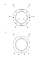
- (A) is a top view of two exchange bodies,
- (b) is a top view of two suppression bodies.
- the stationary component 1 of a steam turbine 90 As shown in FIG. 1, the stationary component 1 of the present invention is installed inside a steam turbine 90.
- the steam turbine 90 includes a casing 91, a casing 92 hermetically sealed by the casing 91, an adjustment valve 93 that adjusts the amount and pressure of the steam S flowing into the casing 92,
- a turbine rotor 95 is provided inside the casing 91 so as to be rotatable around a rotation axis C, and transmits power to a machine such as a generator (not shown), and a plurality of bearing portions that support the turbine rotor 95 so as to be rotatable around the axis.
- the interior of the passenger compartment 92 is formed such that the steam S flows from the upstream U to the downstream L.
- the pressure of the upstream side U is relatively higher than that of the downstream side L, and the steam S becomes lower in pressure as it flows to the downstream side L.
- the direction orthogonal to the direction of the rotation axis C of the turbine rotor 95 is referred to as the radial direction
- the side close to the radial rotation axis C is the inner side in the radial direction
- the side far from the radial rotation axis C. Is called the outside in the radial direction.
- the upstream side U and the downstream side L of the flow of the steam S used in the present embodiment show a relative positional relationship.
- the turbine rotor 95 housed in the passenger compartment 92 includes a shaft 96 and a moving blade 97 that is detachably provided on the outer peripheral surface of the shaft 96.
- a plurality of moving blades 97 are provided at a predetermined interval from the upstream U to the downstream L, thereby forming a moving blade group.
- Each rotor blade 97 is formed continuously around the shaft 96 by attaching a half segment to the shaft 96.
- a stationary blade 10 extending from the inner peripheral surface side of the casing 91 toward the central axis C of the shaft 96 is provided in the vehicle interior 92. Similar to the moving blades 97, a plurality of stationary blades 10 are provided from the upstream U to the downstream L at a predetermined interval to constitute a stationary blade group. The respective stationary blades 10 are arranged alternately with the moving blades 97 by being arranged on the upstream side U of the moving blades 97 constituting the moving blade group.
- the stationary blade 10 is a constituent element of the stationary component 1, but in this embodiment, the exchanger 30 described later is applied to the two stationary blades 10 on the downstream side L among the plurality of stationary blades 10.
- the stationary component 1 is a means for supporting the stationary blade 10 in addition to the stationary blade 10 described above.
- a support 50 a support 50.
- the second stationary component 1 from the downstream side L will be described as an example.
- Partition body 20 The partition body 20 is provided to ensure that the steam S from the upstream side U flows to the downstream side L via the moving blade 97.
- the partition 20 is provided continuously to the inner peripheral surface of the casing 91.
- the partition 20 is configured by a combination of two segments 20 ⁇ / b> A and 20 ⁇ / b> B having a halved shape.
- the main body 21 of the partition 20 has a recess 22 as a storage area for storing a part of the support 50.
- an upstream partition 28 that partitions the recess 22 from the upstream side U
- a downstream partition 29 that partitions the recess 22 from the downstream side L
- a bottom floor 23 that partitions the recess 22 from the radial direction.
- the depression 22, the bottom floor 23, the upstream partition 28, and the downstream partition 29 are continuous in the circumferential direction.
- the connection part of the partition 20 and the support body 50 has an inlay structure.
- the hatching of the exchanger 30 is omitted.
- the bottom floor 23 is formed in parallel to the rotation axis C.
- the bottom floor 23 includes a holding groove 25 as a part of the upstream side U is retracted radially inward from the other regions.
- the recess 22 accommodates the exchange body 30 in an area corresponding to the holding groove 25, and accommodates a part of the front end side of the support body 50 on the downstream side L from this area.
- the illustration of the partition 20 is omitted in FIG. 3, a necessary gap is provided between the bottom floor 23 and the tip of the support body 50 in consideration of thermal expansion during the operation of the steam turbine 90. Yes.
- the upstream partition 28 supports an exchange 30 described later from a side surface 28A facing the recess 22.
- the upstream partition 28 has a dimension that protrudes radially outward from the bottom floor 23 as compared with the downstream partition 29, and its height exceeds half of the support 50 in the radial direction. By setting the height in this way, the partition 20 ensures a region overlapping with the support 50 in the radial direction and ensures support to the rotation axis C.
- the flow guide 27 is integrally provided with the main body 21 by reducing the inner diameter in the radial direction.
- the flow guide 27 guides the flow of steam downstream, and is disposed so as to face the tip of the corresponding moving blade 97.
- the exchange body 30 corresponding to the second support body of the present invention is a member that substitutes for a portion where the erosion is likely to occur in the partition body 20, and with the partition body 20 on the upstream side based on the direction in which the steam S flows. By being detachably provided on the partition 20 between the supports 50, replacement work at the time of maintenance and inspection is facilitated.
- the exchange body 30 is formed in an annular shape so as to be continuous in the circumferential direction of the vehicle interior 92.
- the exchange body 30 is configured by a combination of two segments 30A and 30B having a halved shape for the convenience of being arranged around the partition body 20.
- the exchange body 30 has a rectangular cross section, and the height H from the bottom floor 23 when the partition body 20 is disposed at a predetermined position is the height of the upstream partition 28. Match the height. That is, the outer diameter surface of the upstream partition 28 and the outer diameter surface of the exchanger 30 are flush with each other, and there is no step between them, so that the scale that causes erosion and corrosion is retained. Can be reduced.
- the exchanger 30 has a certain thickness (dimension in the direction of the rotation axis C) from the outer peripheral side toward the inner peripheral side, and the insertion end 31 whose innermost peripheral side is thinned, And an opposed outer diameter surface 32. The thickness and height (diameter dimension) of the insertion end 31 are set so that the insertion end 31 is inserted into the holding groove 25 without a gap.
- the exchange body 30 is fixed to the partition body 20 by bolts B1.
- the bolt B ⁇ b> 1 passes through the bolt hole 33 formed in the exchange body 30 and is fastened to the partition body 20.
- the bolt B1 is inserted to a predetermined position for fixing the exchange body 30 to the partition body 20, the bolt B1 is placed so that its head is accommodated in the exchange body 30 and only the tip surface thereof is exposed from the exchange body 30.
- the dimension of the bolt hole 33 is set.
- the bolt B1 can be a hexagon socket bolt. The same applies to the bolt B2.
- fastening with a plurality of bolts B ⁇ b> 1 and bolt holes 33 at equal intervals in the circumferential direction contributes to improving the adhesion between the exchange body 30 and the partition body 20. Thereby, it is possible to prevent the steam S from flowing between the exchanger 30 and the partition body 20.
- interval of fastening may not be uniform.
- the outer diameter surface 32 is exposed in the vehicle interior 92.
- the exposed outer diameter surface 32 collides with water droplets flowing from the upstream U in the passenger compartment 92 in the stationary component 1 and accumulates the collided water droplets.
- the exchange body 30 is formed of a material having higher wear resistance than both the partition body 20 and the support body 50, that is, a material having high erosion resistance. As a result, a part of the wear-resistant exchanger 30 is exposed at a location where erosion is likely to occur, and erosion can be effectively prevented from occurring.
- the restraining body 40 fixes the exchange body 30 to the partition body 20.
- the suppressing body 40 is formed in an annular shape so as to be continuous in the circumferential direction of the casing 91.
- the restraining body 40 is configured by a combination of two segments 40A and 40B having a halved shape for convenience of arrangement around the partition body 20.
- the restraining body 40 has an L-shaped cross section, and a restraining side 43 that fixes the restraining body 40 to the partition body 20 and a restraint that presses the replacement body 30 toward the partition body 20. Side 45.
- the restraining side 45 covers a part of the head of the bolt B1 that fixes the exchanger 30. Thereby, it is possible to prevent the bolt B1 fastening the exchanger 30 from falling off.
- the suppression body 45 presses the replacement body 30 toward the upstream partition 28 of the partition 20.
- the support of the exchange body 30 with respect to the partition body 20 can be made more reliable.
- the surface of the restraining side 45 and the fixed side 43 that is in contact with the support body 50 has a very small gap between the restraining body 40 and the support body 50 when the restraint body 40 is inserted into the holding groove 51 of the support body 50. It is formed to be a gap.
- the restraint body 40 of this embodiment has an L-shaped cross section, it can have the fixed side 43 and the restraint side 45 with a minimum cross-sectional area, in other words, a small amount of material. .
- a fixed side 43 is fastened to the partition body 20 by a bolt B ⁇ b> 2, and therefore, a bolt hole 41 penetrating the front and back of the fixed side 43 is provided in communication with the support body 50.
- the dimensions of the bolt B ⁇ b> 1 and the bolt hole 41 are set so that the head of the bolt B ⁇ b> 2 that has been fastened is accommodated inside the fixed side 43 and only the tip surface is exposed from the fixed side 43. By doing so, the clearance gap between the support body 50 and the bottom floor 23 of the partition 20 can be suppressed to the minimum.
- the deterrent body 40 may be formed of the same material as the exchanger 30 or may be formed of a different material, but is preferably formed of a material having high corrosion resistance.
- the support body 50 supports the stationary blade 10 via the partition body 20.
- the support body 50 corresponding to the first support body of the present invention extends from the inner peripheral surface of the casing 91 toward the central axis of the turbine rotor 95 and is formed in a semicircular shape that is continuous in the circumferential direction of the casing 91. ing.
- a holding groove 51 into which the restraining body 40 is inserted is formed on the side surface of the upstream side U of the support body 50.
- the support body 50 has an outer diameter surface side fixed to the inner peripheral surface of the casing 91 by welding or other means, and the partition body 20 is fixed to the inner diameter surface side.
- the support body 50 also has an annular shape, but is configured by combining two halved members.
- the support body 50 supports the partition body 20 by accommodating the inner diameter side of the support body 50 in the recess 22 of the partition body 20.
- the stationary component 1 including the partition body 20, the exchange body 30, the suppression body 40, and the support body 50 described above has the inner diameter side of the support body 50 accommodated in the recess 22 of the partition body 20, and the partition body 20 is the support body. 50.
- the exchange body 30 is fixed to the partition body 20 by fastening the restraining body 40 fixed to the partition body 20 and the bolt B1 to the partition body 20.
- the suppression body 40 is not exposed to the outside by being interposed between the three members of the partition body 20, the exchange body 30, and the support body 50.
- this embodiment can remove the used exchange body 30 from the partition body 20 by removing the volt
- the moving blade 97 can be removed from the turbine rotor 95 prior to the work of separating the partition 20 and the support 50.
- a new exchanger 30 prepared separately is disposed at a predetermined position where the insertion end 31 is inserted into the holding groove 25 of the partition body 20.
- positioned exchange body 30 is fixed to the partition 20 with the volt
- the partition body 20 is fixed to the support body 50 in the reverse order of the removal work, and the replacement work of the replacement body 30 is completed.
- the exchanger 30 is detachably attached. Therefore, even if erosion occurs in the exchange body 30, it is only necessary to exchange the exchange body 30, and it is not necessary to replace the partition body 20 as a whole. Therefore, since the members to be replaced can be minimized, the cost of maintenance / inspection work can be suppressed at a low cost.
- the replacement work of the suppressor 40 is the same.
- the replacement body 30 can be replaced by attaching and detaching bolts. Therefore, the replacement body 30 can be replaced without moving to a special environment. Can be reduced.
- the exchange body 30 of the present embodiment has a rectangular cross section, but the form of the exchange body of the present invention is not limited to this. Since the exchanger of the present invention is provided corresponding to the erosion of the contact portion between the partition 20 and the support 50 on the upstream side U, as long as the exchanger is provided in the region, the form is Is optional. For example, an exchanger having an L-shaped cross section can be used.
- the insertion end 31 is inserted into the holding groove 25, but the present invention is not limited to this.
- the lower end of the exchanger 30 may simply be placed on the flat bottom floor 23.
- the exchanger 30 may be attached to the support body 50. Also in this case, the exchange body 30 is fixed to the support body 50 with a bolt. It is preferable that the bolt penetrates the exchanger 30 and is fastened to the support member 50 so that the head is accommodated in the exchanger 30 as in the above-described embodiment.
- the outer diameter surface (32) of the exchanger 30 thus attached is exposed in the vehicle interior 92. Even when the exchanger 30 is attached to the support 50, a groove into which the exchanger 30 is inserted may be formed on the side surface of the upstream partition 28.
- the portion of the deterrence side 45 of the deterrence body 40 can be lengthened to cover the tip of the support body 50. If it does so, while being able to suppress that erosion generate
- the shape of the cross section of the deterrent body 40 is not limited to the L shape, and the form thereof is arbitrary as long as it has the deterring part and the fixing part.
- the cross section may be a triangle or a rectangle.
- fastening by bolts B1 and B2 is adopted as means for attaching the exchange body 30 or the like, but other methods may be adopted as long as they are detachably attached.
- both the replacement body 30 and the restraining body 40 are detachably attached by fastening means using bolts, but only one of them may be attached by fastening means.
- the present invention is applied to the two stationary parts 1 on the downstream side L.
- the present invention is applied to one or more stationary parts 1 among the plurality of stationary parts 1. May be.
- a recess can be provided on the support 50 side, and a part to be inserted into the recess can be provided on the partition 20 side.
- Stator blade 10 Stator blade 20 Partition body 20A, 20B Segment 21 Main body 22 Recess 23 Bottom floor 25 Holding groove 27 Flow guide 28 Upstream partition 29 Downstream partition 30 Exchanger 30A, 30B Segment 31 Insertion end 32 Outer diameter surface 33 Bolt hole 40 Suppressing body 40A, 40B Segment 41 Bolt hole 43 Fixed side 45 Suppressing side 50 Support body 51 Holding groove 90 Steam turbine 91 Casing 92 Car compartment 93 Adjusting valve 95 Turbine rotor 97 Rotor blade 98 Bearing part
Landscapes
- Engineering & Computer Science (AREA)
- Mechanical Engineering (AREA)
- General Engineering & Computer Science (AREA)
- Turbine Rotor Nozzle Sealing (AREA)
Abstract
Une turbine à vapeur (90) selon la présente invention est pourvue : d'aubes de stator (10) agencées dans un compartiment (92) à l'intérieur d'un boîtier à travers lequel s'écoule de la vapeur depuis un côté amont vers un côté aval ; de moyens de support pour porter les aubes de stator (10) dans le boîtier. La turbine à vapeur est caractérisée en ce que chaque moyen de fixation comprend : un premier corps de support (corps de support 50) fixé au boîtier ; un second corps de support (corps de séparation 20) reliant l'aube de stator (10) au premier corps de support ; un corps d'échange (30) qui est disposé de façon détachable entre le premier corps de support et le second corps de support, sur le côté amont du premier corps de support par rapport à la direction dans laquelle s'écoule la vapeur.
Priority Applications (4)
| Application Number | Priority Date | Filing Date | Title |
|---|---|---|---|
| JP2018501394A JP6578053B2 (ja) | 2016-02-23 | 2016-02-23 | 蒸気タービン |
| US16/065,675 US10612419B2 (en) | 2016-02-23 | 2016-02-23 | Steam turbine |
| PCT/JP2016/000945 WO2017145190A1 (fr) | 2016-02-23 | 2016-02-23 | Turbine à vapeur |
| EP16891353.1A EP3379038B1 (fr) | 2016-02-23 | 2016-02-23 | Turbine à vapeur |
Applications Claiming Priority (1)
| Application Number | Priority Date | Filing Date | Title |
|---|---|---|---|
| PCT/JP2016/000945 WO2017145190A1 (fr) | 2016-02-23 | 2016-02-23 | Turbine à vapeur |
Publications (1)
| Publication Number | Publication Date |
|---|---|
| WO2017145190A1 true WO2017145190A1 (fr) | 2017-08-31 |
Family
ID=59684863
Family Applications (1)
| Application Number | Title | Priority Date | Filing Date |
|---|---|---|---|
| PCT/JP2016/000945 Ceased WO2017145190A1 (fr) | 2016-02-23 | 2016-02-23 | Turbine à vapeur |
Country Status (4)
| Country | Link |
|---|---|
| US (1) | US10612419B2 (fr) |
| EP (1) | EP3379038B1 (fr) |
| JP (1) | JP6578053B2 (fr) |
| WO (1) | WO2017145190A1 (fr) |
Citations (6)
| Publication number | Priority date | Publication date | Assignee | Title |
|---|---|---|---|---|
| US20060153683A1 (en) * | 2004-04-19 | 2006-07-13 | Dube David P | Anti-rotation lock |
| FR2929983A1 (fr) * | 2008-04-14 | 2009-10-16 | Snecma Sa | Secteur de distributeur de turbine de turbomachine. |
| EP2206885A1 (fr) * | 2009-01-08 | 2010-07-14 | Siemens Aktiengesellschaft | Turbine à gaz |
| JP2012097601A (ja) * | 2010-10-29 | 2012-05-24 | Mitsubishi Heavy Ind Ltd | タービン及びタービンの製造方法 |
| JP2012180748A (ja) * | 2011-02-28 | 2012-09-20 | Mitsubishi Heavy Ind Ltd | 回転機械の静翼ユニット、回転機械の静翼ユニットの製造方法及び回転機械の静翼ユニットの結合方法 |
| JP2014047668A (ja) * | 2012-08-30 | 2014-03-17 | Mitsubishi Heavy Ind Ltd | 軸流回転機械、その静翼環、及び静翼環の組付け方法 |
Family Cites Families (6)
| Publication number | Priority date | Publication date | Assignee | Title |
|---|---|---|---|---|
| US3300180A (en) * | 1964-11-17 | 1967-01-24 | Worthington Corp | Segmented diaphragm assembly |
| JPS57204406U (fr) * | 1981-06-24 | 1982-12-25 | ||
| JPS58146003U (ja) | 1982-03-26 | 1983-10-01 | 三菱重工業株式会社 | 蒸気タ−ビンにおける車室と仕切板との嵌合部の隙間調整装置 |
| JPS6073806U (ja) | 1983-10-27 | 1985-05-24 | 三菱重工業株式会社 | 耐エロ−ジヨン性を改善したタ−ビン部品 |
| JP4918263B2 (ja) * | 2006-01-27 | 2012-04-18 | 三菱重工業株式会社 | 軸流圧縮機の静翼環 |
| US7645117B2 (en) * | 2006-05-05 | 2010-01-12 | General Electric Company | Rotary machines and methods of assembling |
-
2016
- 2016-02-23 WO PCT/JP2016/000945 patent/WO2017145190A1/fr not_active Ceased
- 2016-02-23 EP EP16891353.1A patent/EP3379038B1/fr active Active
- 2016-02-23 US US16/065,675 patent/US10612419B2/en active Active
- 2016-02-23 JP JP2018501394A patent/JP6578053B2/ja active Active
Patent Citations (6)
| Publication number | Priority date | Publication date | Assignee | Title |
|---|---|---|---|---|
| US20060153683A1 (en) * | 2004-04-19 | 2006-07-13 | Dube David P | Anti-rotation lock |
| FR2929983A1 (fr) * | 2008-04-14 | 2009-10-16 | Snecma Sa | Secteur de distributeur de turbine de turbomachine. |
| EP2206885A1 (fr) * | 2009-01-08 | 2010-07-14 | Siemens Aktiengesellschaft | Turbine à gaz |
| JP2012097601A (ja) * | 2010-10-29 | 2012-05-24 | Mitsubishi Heavy Ind Ltd | タービン及びタービンの製造方法 |
| JP2012180748A (ja) * | 2011-02-28 | 2012-09-20 | Mitsubishi Heavy Ind Ltd | 回転機械の静翼ユニット、回転機械の静翼ユニットの製造方法及び回転機械の静翼ユニットの結合方法 |
| JP2014047668A (ja) * | 2012-08-30 | 2014-03-17 | Mitsubishi Heavy Ind Ltd | 軸流回転機械、その静翼環、及び静翼環の組付け方法 |
Also Published As
| Publication number | Publication date |
|---|---|
| EP3379038A4 (fr) | 2019-01-02 |
| EP3379038B1 (fr) | 2020-01-15 |
| JP6578053B2 (ja) | 2019-09-18 |
| US10612419B2 (en) | 2020-04-07 |
| US20190003338A1 (en) | 2019-01-03 |
| EP3379038A1 (fr) | 2018-09-26 |
| JPWO2017145190A1 (ja) | 2018-10-11 |
Similar Documents
| Publication | Publication Date | Title |
|---|---|---|
| RU2532868C2 (ru) | Направляющий аппарат турбины для газотурбинного двигателя, сектор направляющего аппарата, непрерывный кольцевой кронштейн, турбина низкого давления газотурбинного двигателя и газотурбинный двигатель | |
| US7484928B2 (en) | Repaired turbine nozzle | |
| JP5759363B2 (ja) | ターボ機械用のセクタ化された分配器 | |
| US8727719B2 (en) | Annular flange for fastening a rotor or stator element in a turbomachine | |
| US8684683B2 (en) | Gas turbine nozzle attachment scheme and removal/installation method | |
| EP2620591B1 (fr) | Ensemble d'aube de stator de moteur à turbine à gaz avec virole interne | |
| US9506653B2 (en) | Combustion chamber of a gas turbine | |
| KR101671650B1 (ko) | 축류 배기 터빈 | |
| US8979484B2 (en) | Casing for an aircraft turbofan bypass engine | |
| US9822669B2 (en) | Turbine assembly with detachable struts | |
| US9745852B2 (en) | Axial rotor portion and turbine rotor blade for a gas turbine | |
| US20040100030A1 (en) | Brush seal with adjustable clearance | |
| US20140301841A1 (en) | Turbomachine compressor guide vanes assembly | |
| JP6578053B2 (ja) | 蒸気タービン | |
| JP2017520709A (ja) | ガスタービンエンジンのための軸受支持ハウジング | |
| US20140003926A1 (en) | Compressor for a gas turbine and method for repairing and/or changing the geometry of and/or servicing said compressor | |
| CN104564171A (zh) | 密封装置 | |
| US9650918B2 (en) | Austenitic segment for steam turbine nozzle assembly, and related assembly | |
| US11965432B2 (en) | Guide vane ring with wear elements | |
| EP3179045A1 (fr) | Segment de tuyère de turbine ayant une paroi latérale complète et conception de crochet intégré | |
| JP6132737B2 (ja) | 蒸気タービン |
Legal Events
| Date | Code | Title | Description |
|---|---|---|---|
| ENP | Entry into the national phase |
Ref document number: 2018501394 Country of ref document: JP Kind code of ref document: A |
|
| WWE | Wipo information: entry into national phase |
Ref document number: 2016891353 Country of ref document: EP |
|
| ENP | Entry into the national phase |
Ref document number: 2016891353 Country of ref document: EP Effective date: 20180620 |
|
| NENP | Non-entry into the national phase |
Ref country code: DE |