WO2017145291A1 - 刃切断装置及び刃切断方法 - Google Patents
刃切断装置及び刃切断方法 Download PDFInfo
- Publication number
- WO2017145291A1 WO2017145291A1 PCT/JP2016/055461 JP2016055461W WO2017145291A1 WO 2017145291 A1 WO2017145291 A1 WO 2017145291A1 JP 2016055461 W JP2016055461 W JP 2016055461W WO 2017145291 A1 WO2017145291 A1 WO 2017145291A1
- Authority
- WO
- WIPO (PCT)
- Prior art keywords
- shaped material
- blade
- unit
- belt
- strip
- Prior art date
- Legal status (The legal status is an assumption and is not a legal conclusion. Google has not performed a legal analysis and makes no representation as to the accuracy of the status listed.)
- Ceased
Links
Images




Classifications
-
- B—PERFORMING OPERATIONS; TRANSPORTING
- B21—MECHANICAL METAL-WORKING WITHOUT ESSENTIALLY REMOVING MATERIAL; PUNCHING METAL
- B21D—WORKING OR PROCESSING OF SHEET METAL OR METAL TUBES, RODS OR PROFILES WITHOUT ESSENTIALLY REMOVING MATERIAL; PUNCHING METAL
- B21D53/00—Making other particular articles
- B21D53/60—Making other particular articles cutlery wares; garden tools or the like
- B21D53/64—Making other particular articles cutlery wares; garden tools or the like knives; scissors; cutting blades
-
- B—PERFORMING OPERATIONS; TRANSPORTING
- B21—MECHANICAL METAL-WORKING WITHOUT ESSENTIALLY REMOVING MATERIAL; PUNCHING METAL
- B21D—WORKING OR PROCESSING OF SHEET METAL OR METAL TUBES, RODS OR PROFILES WITHOUT ESSENTIALLY REMOVING MATERIAL; PUNCHING METAL
- B21D37/00—Tools as parts of machines covered by this subclass
- B21D37/20—Making tools by operations not covered by a single other subclass
-
- B—PERFORMING OPERATIONS; TRANSPORTING
- B21—MECHANICAL METAL-WORKING WITHOUT ESSENTIALLY REMOVING MATERIAL; PUNCHING METAL
- B21D—WORKING OR PROCESSING OF SHEET METAL OR METAL TUBES, RODS OR PROFILES WITHOUT ESSENTIALLY REMOVING MATERIAL; PUNCHING METAL
- B21D37/00—Tools as parts of machines covered by this subclass
- B21D37/20—Making tools by operations not covered by a single other subclass
- B21D37/205—Making cutting tools
-
- B—PERFORMING OPERATIONS; TRANSPORTING
- B21—MECHANICAL METAL-WORKING WITHOUT ESSENTIALLY REMOVING MATERIAL; PUNCHING METAL
- B21D—WORKING OR PROCESSING OF SHEET METAL OR METAL TUBES, RODS OR PROFILES WITHOUT ESSENTIALLY REMOVING MATERIAL; PUNCHING METAL
- B21D43/00—Feeding, positioning or storing devices combined with, or arranged in, or specially adapted for use in connection with, apparatus for working or processing sheet metal, metal tubes or metal profiles; Associations therewith of cutting devices
- B21D43/28—Associations of cutting devices therewith
-
- B—PERFORMING OPERATIONS; TRANSPORTING
- B21—MECHANICAL METAL-WORKING WITHOUT ESSENTIALLY REMOVING MATERIAL; PUNCHING METAL
- B21D—WORKING OR PROCESSING OF SHEET METAL OR METAL TUBES, RODS OR PROFILES WITHOUT ESSENTIALLY REMOVING MATERIAL; PUNCHING METAL
- B21D43/00—Feeding, positioning or storing devices combined with, or arranged in, or specially adapted for use in connection with, apparatus for working or processing sheet metal, metal tubes or metal profiles; Associations therewith of cutting devices
- B21D43/28—Associations of cutting devices therewith
- B21D43/287—Devices for handling sheet or strip material
Definitions
- the present invention relates to a blade cutting device and a blade cutting method.
- a container made of a sheet material such as paperboard or cardboard is formed by punching the sheet material with a punching machine, forming a blank having a shape corresponding to the structure of the container, and bending the blank into a predetermined shape. It has become.
- the punching machine has an upper surface plate and a lower surface plate, a punching die is attached to the upper surface plate, a cutting plate is attached to the lower surface plate, a sheet material is placed on the cutting plate, and the upper surface plate is lowered and pressed against the lower surface plate.
- the sheet material is punched, a blank is formed, and a ruled line for bending is formed on the blank.
- a groove having a predetermined pattern is formed in the punching die, and various punching blades for punching a sheet material and various ruled line blades for forming a ruled line for bending are embedded in the groove.
- a sharp cutting edge is formed at the lower end of the punching blade, and a rounded cutting edge is formed at the lower end of the ruled line blade.
- a blade cutting device for forming the punching blade and the ruled blade.
- graphic data representing the shapes and dimensions of the punching blade and the ruled blade are extracted from CAD data designed for punching by a punching machine, and the punching blade is based on the graphic data.
- belt-shaped material used as the material of a ruled line blade is cut
- the punching blade and the ruled line blades are used one by one by using the band-shaped material specified in the graphic data and cutting the band-shaped material into the dimensions specified in the graphic data. Since it is necessary to form, the operation
- the operation of selecting the strip-shaped material necessary for forming the punching blade and the ruled line blade from many kinds of strip-shaped materials becomes complicated, and the punching blade and the ruled line blade may not be formed with high accuracy. .
- the present invention provides a blade cutting device and a blade cutting method capable of solving the problems of the conventional blade cutting device, simplifying the work of cutting the strip-shaped material, and forming the blade with high accuracy.
- the purpose is to do.
- the material storage unit including a plurality of storage chambers for storing the band-shaped material, which is a material for forming the blade, for each type, and among the plurality of storage chambers
- a transport unit that transports the strip-shaped material drawn out from the predetermined storage chamber, a strip-shaped material processing section including a cutting unit that cuts the transported strip-shaped material into a predetermined length to form a blade, and the material storage section
- a control unit that places a predetermined storage chamber of the material storage unit at a position facing the belt-shaped material processing unit.
- the material storage section including a plurality of storage chambers for storing the band-shaped material, which is a material for forming the blade, for each type, and the plurality of storage chambers
- a belt-shaped material processing unit including a transport unit that transports a belt-shaped material drawn out of a predetermined storage chamber, and a cutting unit that cuts the transported belt-shaped material into a predetermined length to form a blade; and
- a control unit that moves the material storage unit and places a predetermined storage chamber of the material storage unit in a position facing the belt-shaped material processing unit.
- the band-shaped material is divided into types and set in a plurality of storage chambers of the material storage unit, and a predetermined storage chamber among the plurality of storage chambers is placed at a position facing the band-shaped material processing unit,
- the strip material drawn from the storage chamber is transported by the transport unit and cut into a predetermined length by the cutting unit to form a blade. Therefore, the strip shape necessary to form the blade from many types of strip material
- the operation of selecting the material can be simplified, and the blade can be formed with high accuracy.
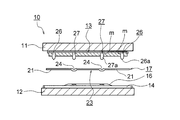
- Fig. 2 is a conceptual diagram of the punching machine.
- 10 is a punching machine
- 11 is an upper surface plate
- 12 is a lower surface plate
- 13 is a punching die attached to the upper surface plate
- 14 is a cutting plate attached to the lower surface plate
- 16 is a cutting plate 14. It is an attached face plate.
- a sheet material 17 such as paperboard or cardboard is placed on the face plate 16, the upper surface plate 11 is lowered and pressed against the lower surface plate 12, the sheet material 17 is punched along the cutting line 21, and the blank 23 is formed. At the same time, a ruled line 24 for bending is formed in the blank 23.
- a groove m having a predetermined pattern is formed in the punching die 13, and a punching blade 26 and a ruled line 24 as various first blades for punching the sheet material 17 are formed in the groove m.
- the ruled line blade 27 as the various second blades is embedded, and a sharp blade edge 26 a is formed at the lower end of the punching blade 26, and a rounded blade edge 27 a is formed at the lower end of the ruled line blade 27.
- the punching blade 26 and the ruled line blade 27 are formed by cutting a metal belt-shaped strip material, which is a material, into a predetermined length by a blade cutting device, but the shape of the blank 23 is complicated.
- the shape of the groove m formed on the punching die 13 becomes complicated, and the number of the punching blades 26 and the ruled line blades 27 increases.
- the types of punching blades 26 and ruled line blades 27 increase, but also the types of belt-shaped materials increase.
- the operation of selecting the strip material necessary for forming the punching blade 26 and the ruled line blade 27 from many types of strip materials becomes complicated, and the punching blade 16 and the ruled line blade 27 are made accurate. It may not be well formed.
- a blade cutting apparatus which can simplify the operation of selecting a strip-shaped material and can form the punching blade 26 and the ruled line blade 27 with high accuracy.
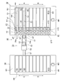
- FIG. 1 is a conceptual diagram of a blade cutting device according to an embodiment of the present invention
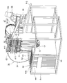
- FIG. 3 is a perspective view of the blade cutting device according to the embodiment of the present invention
- FIG. 4 is a side view of the blade cutting device according to the embodiment of the present invention.
- 5 is a plan view of the blade cutting device according to the embodiment of the present invention
- FIG. 6 is a rear view of the blade cutting device according to the embodiment of the present invention
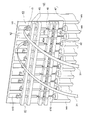
- FIG. 7 is a view of the belt-shaped material guide portion according to the embodiment of the present invention.
- FIG. 8 is a perspective view of a main part of the belt-shaped material guide portion in the embodiment of the present invention
- FIG. 9 is a perspective view of the blade accommodating portion in the embodiment of the present invention
- FIG. 10 is in the embodiment of the present invention. It is a mechanism figure of a blade cutting device.
- 30 is a blade cutting device
- 31 is a strip-like material that is a blade material such as a punching blade 26 (FIG. 2), a ruled blade 27, and the like 32 is movable in the directions of arrows A and B with respect to the frame Fr1.
- the material accommodating portion 33 that accommodates the belt-shaped material 31 is fixed to the frame Fr2, and the belt-shaped material processing portion 34 for cutting the belt-shaped material 31 into a predetermined length to form a blade
- a blade accommodating portion that is disposed so as to be movable in the directions of arrows C and D with respect to the frame Fr2 and that is formed by cutting in the band-shaped material processing portion 33
- M1 designates the material accommodating portion 32 with an arrow A.
- M2 is a motor as a drive unit for moving in the B direction
- M2 is a motor as a drive unit for moving the blade housing portion 34 in the directions of arrows C and D.
- the material accommodating portion 32 includes a plurality of partition walls wa each extending in parallel with each other, and in the present embodiment, having eleven “U” -shaped shapes.
- a wound strip-shaped material 31 that is, a roll (coil) Cr, is stored separately for each type.
- the strip-shaped material 31 is accommodated in the material accommodating part 32 in the state of the roll Cr, when it is pulled out from the material accommodating part 32, a curl is attached. Therefore, in the present embodiment, the band-shaped material 31 drawn out from each storage chamber Ri is taken into the end of the material storage section 32 on the side of the band-shaped material processing section 33, conveyed, and guided to the material storage section 32. At the same time, a belt-shaped material guide 41 that takes the curl attached to the belt-shaped material 31 is disposed.
- the belt-shaped material 31 is placed at the standby position.
- ten gate units gi (i 1, 2,..., 10).
- the roller r3 as tenth second support members that are arranged freely and that support the belt-like material 31 by pushing the belt-like material 31 from below at a predetermined position in the height direction, abut against the lower end of the bar 45.
- a screw 46 as a position adjusting element disposed so as to be rotatable with respect to the take-in plate member 43 and movable in the vertical direction
- a knob as an operating element disposed at the lower end of the screw 46 47. Therefore, the operator of the blade cutting device 30 can adjust the position of the roller r3 by rotating the knob 47 to rotate the screw 46 and moving the bar 45 and the roller r3 in the vertical direction.
- the take-in plate member 43 is provided with a hole through which the bar 45 penetrates, holding members 43a and 43b that hold the bar 45 movably, and a screw hole that is screwed with the screw 46.
- a holding member 43c is formed to protrude so as to be rotatable and movable.
- the rollers r1 to r3 are arranged along the conveying direction of the belt-like material 31, the rollers r1 push the belt-like material 31 from above while rotating, and the rollers r2, r3 rotate while the belt-like material 31 is rotating. Is pushed from below, so that the curl attached to the belt-like material 31 can be removed while the belt-like material 31 is conveyed.
- the strength of the curl attached to the belt-like material 31 varies depending on the type of the belt-like material 31, for example, the material, thickness, width, etc.
- the take-up height is adjusted, so that the curl attached to the band-shaped material 31 can be surely taken according to the type of the band-shaped material 31.
- the rollers r1 to r3 constitute a curl wrinkle eliminating unit for removing curl from the belt-like material 31.
- the position of the roller r3 among the rollers r1 to r3 is adjusted.
- a belt-like shape is obtained.
- the curl attached to the material 31 can be taken according to the type of the band-shaped material 31.
- Each of the gate portions gi places the band-shaped material 31 at a standby position on the downstream side of the roller r1 in the conveying direction of the band-shaped material 31 or selects the band-shaped material 31 drawn out from a predetermined storage chamber Ri. To the processing unit 33.
- each gate portion gi includes a gate 48 that opens and closes the transport path of the belt-shaped material 31 and an air cylinder 49 as an actuator for driving the gate 48, and each gate 48 is contacted and separated in the vertical direction.
- Plates 48a and 48b are provided as a pair of clamping members that are freely arranged.
- the transport path of the strip material 31 is opened, and the strip material 31 can be transported. Further, when the plate 48a is placed at the lower position and brought into contact with the plate 48b, the transport path of the strip material 31 is closed, and the strip material 31 is sandwiched between the plates 48a and 48b and is not transported. At this time, the belt-like material 31 is placed at the standby position. Since each belt-like material 31 placed at the standby position is sandwiched between the plates 48a and 48b, the belt-like material 31 is prevented from moving to a position deviated from the standby position due to vibration, self-weight, etc. generated in the blade cutting device 30. be able to.
- the band-shaped material processing section 33 is disposed at the upstream end in the transport direction of the band-shaped material 31 so as to face one of the gate sections gi, and is drawn out from a predetermined storage chamber Ri.
- the gate section gi A first transport unit 51 that transports the one strip-shaped material 31 that is selected and guided in FIG. 1, and is disposed downstream of the first transport unit 51 in the transport direction of the strip-shaped material 31 and transports the strip-shaped material 31.
- the encoder 53 as a conveyance amount detection unit that is disposed adjacent to the second conveyance unit 52 between the two conveyance units 52 and the first and second conveyance units 51 and 52 and detects the conveyance amount of the belt-shaped material 31.
- the belt-shaped material 31 is disposed on the downstream side of the second transport unit 52 in the transport direction of the strip-shaped material 31 so as to be adjacent to the second transport unit 52, and the strip-shaped material 31 has a predetermined length.
- a cutting unit 55 that cuts to form a blade, a chute 57 as a discharge unit that feeds the blade formed by the cutting unit 55 to the blade housing 34, and the first and second transport units 51 and 52 between the first
- a belt-shaped material sensor 65 is provided as a position detection unit that is disposed adjacent to the transport unit 51 and detects the position of the belt-shaped material 31.
- the first transport unit 51 includes a sandwich transport unit 61 that transports the belt-shaped material 31 by sandwiching it, and an air cylinder 62 as an actuator for driving the sandwich transport unit 61.
- the nipping and conveying unit 61 includes rollers r11 and r12 as a pair of conveying members that are rotatable and can be contacted and separated in the vertical direction, and one of the rollers r11 and r12.
- a motor M3 is provided as a conveyance drive unit for rotating the roller r12 in the forward direction and the reverse direction.
- the air cylinder 62 is connected to the compressor C via the switching valve Va, receives the compressed air sent from the compressor C, drives the nipping / conveying section 61, and moves the roller r11 in the vertical direction.
- the transport path for the strip-shaped material 31 is opened, and the strip-shaped material 31 is not transported.
- the transport path for the strip-shaped material 31 is closed and the strip-shaped material 31 is transported.
- the belt-shaped material 31 is advanced toward the second transport unit 52 when the motor M3 is driven in the forward direction, and is retracted when the motor M3 is driven in the reverse direction.
- the plate 48a When the belt-like material 31 is placed at the standby position in each gate portion gi, the plate 48a is placed at the lower position, and the belt-like material 31 is sandwiched between the plates 48a and 48b.
- the roller r11 In the first transport unit 51, the roller r11 is It is placed in the upper position, and the conveyance path for the band-shaped material 31 is opened. At this time, the leading end 31a of the belt-like material 31 is slightly projected toward the second transport unit 52 from the position where the rollers r11 and r12 abut each other.
- the second transport unit 52 includes a nipping and conveying unit 64 that conveys the band-shaped material 31 by nipping it.
- the nipping / conveying section 64 has rollers r13 and r14 as a pair of conveying members rotatably arranged, and one of the rollers r13 and r14, in this embodiment, the roller r13 in the forward direction.
- the motor M4 as a drive part for conveyance for rotating to a reverse direction is provided.
- the encoder 53 detects the transport amount of the strip material 31 when the strip material 31 is transported by the first and second transport units 51 and 52.
- the cutting unit 55 includes a mold 56 for cutting the belt-shaped material 31, a motor M5 as a cutting drive unit for driving the mold 56, and a reciprocating motion of the motor M5.
- a movement direction conversion unit 58 for conversion is provided.
- the mold 56 includes a male mold 56a and a female mold 56b, and the movement direction conversion section 58 is rotated by a rotation transmission shaft sh2 screwed with the output shaft sh1 of the motor M5, and the rotation transmission shaft sh2.
- the cam 58a is rotated via the rotation transmission shaft sh2, and the male die 56a is moved in the vertical direction.
- the male mold 56a is separated from the female mold 56b at the upper position, and enters the female mold 56b at the lower position to cut the strip-shaped material 31.
- the blade accommodating portion 34 includes a plurality of, in the present embodiment, 11 partition walls wb extending in parallel to each other, and a plurality of the present embodiments are provided by the partition walls wb.
- blades formed by cutting the strip-shaped material 31 in the cutting unit 55 are stored separately for each type.
- FIG. 11 is a control block diagram of the blade cutting device according to the embodiment of the present invention.
- 71 is a control unit for controlling the entire blade cutting device 30, 72 is a memory as a storage device, 73 is an operation unit comprising an operation panel, etc. 74 is a display unit comprising a liquid crystal panel, a display and the like. . Further, 76 is a motor drive unit that drives each of the motors M1 to M5, 53 is an encoder, 65 is a belt-shaped material sensor, 77 is a pneumatic control unit that drives the air cylinders 49 and 62 by switching the switching valves Vi and Va. It is.
- the encoder 53 includes a rotary encoder, and includes a pair of rotating bodies that sandwich the belt-shaped material 31 (FIG. 1) and are rotated by friction with the belt-shaped material 31 as the belt-shaped material 31 is conveyed. Based on the rotation angle of the rotating body, the transport amount of the belt-like material 31 is detected, and a detection signal is sent to the control unit 71.
- the encoder 53 is provided separately from the motor M4, and Since the transport amount of the strip-shaped material 31 is detected based on the rotation angle of the rotating body rotated by the friction, the transport amount of the strip-shaped material 31 can be detected with high accuracy.
- the strip material sensor 65 detects the position of the strip material 31 transported between the first and second transport units 51 and 52 and sends a detection signal to the control unit 71. In the present embodiment, it is determined from the sensor output of the encoder 53 whether or not the leading end 31a of the band-shaped material 31 has reached between the rollers r13 and r14 of the nipping and conveying unit 64.
- a strip-shaped material sensor is disposed adjacent to the second transport unit 52 on the downstream side of the second transport unit 52 in the transport direction of the strip 31, and the tip of the strip-shaped material 31 is based on a detection signal of the strip-shaped material sensor. It can also be determined whether 31a has reached between the rollers r13 and r14 of the nipping and conveying unit 64.
- FIG. 12 is a flowchart showing the operation of the blade cutting device according to the embodiment of the present invention.
- step S2 when the operator turns on the blade cutting device 30 (step S1), the control unit 71 puts the blade cutting device 30 in an initial state (step S2).
- the gate 48 of each gate portion gi is opened, the plate 48a is placed at the upper position, and in the first transport unit 51, the rollers r11 and r12 of the sandwiching transport portion 61 are stopped.
- the roller r11 is placed at the upper position.
- the rollers r13 and r14 of the nipping and transporting section 64 are stopped, and in the cutting unit 55, the male mold 56a of the mold 56 is placed at the upper position.
- Step S ⁇ b> 3 the control unit 71 reads the CAD data and records it in the memory 72. Subsequently, the control unit 71 reads out and analyzes the CAD data from the memory 72 (step S4), extracts graphic data representing the shape and dimensions of the blade, and performs punching by the punching machine 10 based on the graphic data. The color, thickness, length, etc.
- each strip material 31 Blade / band material information such as names is displayed on the display unit 74 as a list (step S5).
- step S6 an operator sets the roll Cr of the strip
- control unit 71 sends an instruction to the pneumatic control unit 77, switches the switching valve Vi, drives each air cylinder 49, closes the gate 48, and places the plate 48a in the lower position.
- belt-shaped material 31 is set
- the operator rotates the screw 46 by rotating the knob 47 of the position adjusting unit di, moves the bar 45 and the roller r3 in the vertical direction, and moves the roller r3 to the curling hook attached to the belt-shaped material 31. It is placed at a predetermined position in the height direction according to the strength, and the take-in height is adjusted (step S9).
- the control unit 71 sends an instruction to the motor drive unit 76, drives the motors M1 and M2, and moves the material storage unit 32.
- the predetermined storage chamber Ri in which the roll Cr of the strip-shaped material 31 is stored is placed at a position facing the strip-shaped material processing portion 33, that is, at the strip-shaped material processing position, and the blade storage portion 34 is moved to move the strip-shaped material 31.
- a predetermined storage chamber Si in which the blade formed by cutting is stored is placed at a position facing the belt-shaped material processing portion 33, that is, a blade storage position (step S11).
- control unit 71 sends an instruction to the pneumatic control unit 77 and switches the switching valve Vi to open the gate 48 of the gate unit gi corresponding to the storage chamber Ri placed at the belt-shaped material processing position, and the plate 48a Is placed in the upper position and the roller r11 of the first transport unit 51 is placed in the lower position by switching the switching valve Va. Further, the control unit 71 sends an instruction to the motor driving unit 76, drives the motors M3 and M4 in the forward direction, and rotates the rollers r11 to r14. Thereby, the strip
- the encoder 53 starts detecting the transport amount of the strip-shaped material 31 and sends a detection signal to the control unit 71.
- the control unit 71 determines whether or not the leading end 31a of the strip-shaped material 31 has reached between the rollers r13 and r14, and the leading end 31a of the strip-shaped material 31 is the roller r13, When it is determined that the interval r14 has been reached, an instruction is sent to the air pressure control unit 77, the roller r11 is placed in the upper position by switching the switching valve Va, and an instruction is sent to the motor drive unit 76 to stop driving the motor M3. Let Therefore, while the belt-shaped material 31 is transported by the second transport unit 52, the load by the sandwiching transport unit 61 is not applied to the second transport unit 52, so that the belt-shaped material 31 can be transported stably. As a result, the blade can be formed with high accuracy.
- control unit 71 acquires the conveyance amount of the strip material 31 based on the detection signal sent from the encoder 53, and instructs the motor driving unit 76 when the conveyance amount becomes equal to the length of the blade to be formed. , The motor M5 is driven, and the belt-shaped material 31 is cut by the die 56 (step S13).
- the blade formed by cutting the strip-shaped material 31 is discharged through the chute 57 to the storage chamber Si placed at the blade storage position.
- control unit 71 sends an instruction to the motor driving unit 76, drives the motors M3 and M4 in the reverse direction, and rotates the rollers r11 to r14 in the reverse direction.
- disconnecting is conveyed by the 1st, 2nd conveyance units 51 and 52, and is made to retract (step S14).
- the control unit 71 sends an instruction to the motor drive unit 76 and stops driving the motors M3 and M4.
- the control unit 71 sends an instruction to the pneumatic control unit 77 and switches the switching valve Vi to close the gate 48 of the gate unit gi, place the plate 48a in the lower position, and instruct the pneumatic control unit 77 to And the switching valve Va is switched to place the roller r11 of the nipping and conveying unit 61 at the upper position in the first conveying unit 51. In this way, the belt-like material 31 is placed at the standby position (step S15).
- the roll Cr of the strip material 31 is set in the storage chambers R1, R3 of the material storage section 32, and the leading end of the strip material 31 drawn out from the storage chambers R1, R3.
- 31a is slightly protruded toward the second transport unit 52 from the position where the rollers r11 and r12 (FIG. 4) of the first transport unit 51 contact each other, and the belt-like material 31 is placed at the standby position.
- the gate 48 of the gate portion g3 corresponding to the accommodation chamber R3 placed in the belt-shaped material processing position is opened, the plate 48a is placed in the upper position, and in the belt-shaped material processing portion 33,
- the roller r11 of the nipping and conveying unit 61 is placed at the lower position, the motors M3 and M4 are driven in the forward direction, and the rollers r11 to r14 are rotated.
- belt-shaped material 31 pulled out from storage chamber R3 is conveyed by the 1st, 2nd conveyance units 51 and 52, and is advanced.
- the encoder 53 starts detecting the transport amount of the strip-shaped material 31, and when the transport amount of the strip-shaped material 31 becomes equal to the length of the blade, the motor M5 is driven and the die By 56, the strip-shaped material 31 is cut into the dimensions defined in the graphic data. Then, the blade formed by cutting is discharged through the chute 57 to the storage chamber S3 placed at the blade storage position.
- the motors M3 and M4 are driven in the reverse direction, the rollers r11 to r14 are rotated, and the belt-shaped material 31 is transported by the first and second transport units 51 and 52 and retracted.
- the strip material sensor 65 detects the leading end 31a of the strip material 31
- the motors M3 and M4 are stopped, the rollers r11 to r14 are stopped, the gate 48 of the gate portion g3 is closed, and the strip material 31 is on standby. Placed in position.
- the strip-shaped material 31 is divided into types and set in the plurality of storage chambers Ri of the material storage section 32, and a predetermined storage chamber among the plurality of storage chambers Ri is strip-shaped.
- the strip-shaped material 31 placed at the strip-shaped material processing position facing the material processing section 33 and drawn out from the predetermined storage chamber is transported by the first and second transport units 51 and 52, and a predetermined length by the cutting unit 55.
- the blade is formed by cutting.
- a predetermined storage chamber among the plurality of storage chambers Si of the blade storage section 34 is placed at a blade storage position facing the belt-shaped material processing section 33, and the blade formed by the cutting unit 55 is discharged into the predetermined storage chamber. Therefore, the blade according to the strip
- a predetermined number of strip-shaped material processing sections 33 are arranged between the material storage section 32 and the blade storage section 34 in the present embodiment.
- a plurality of, for example, two strip-shaped material processing portions 33 can be arranged in parallel between the material storage portion 32 and the blade storage portion 34. In that case, two of the strip materials 31 taken into the strip material guide 41 are selected and guided to the strip material processing section 33.
- air cylinders 49 and 62 are used as the actuator, but a hydraulic cylinder, a motor, or the like can be used instead of the air cylinders 49 and 62.
Landscapes
- Engineering & Computer Science (AREA)
- Mechanical Engineering (AREA)
- Perforating, Stamping-Out Or Severing By Means Other Than Cutting (AREA)
- Straightening Metal Sheet-Like Bodies (AREA)
Abstract
帯状材料(31)を切断する作業を簡素化することができ、刃を精度よく形成することができるようにする。刃を形成するための帯状材料(31)を種類ごとに分けて収容するための複数の収容室(R1~R10)を備えた資材収容部(32)と、所定の収容室から引き出された帯状材料(31)を搬送する搬送ユニット、及び帯状材料(31)を所定の長さに切断して刃を形成する切断ユニット(55)を備えた帯状材料加工部(33)と、資材収容部(32)を移動させ、資材収容部(32)の所定の収容室を帯状材料加工部(33)と対向する位置に置く制御部とを有する。所定の収容室が帯状材料加工部(33)と対向する位置に置かれ、所定の収容室から引き出された帯状材料(31)が所定の長さに切断されて刃が形成される。帯状材料(31)を選択する作業を簡素化することができ、しかも、刃を精度よく形成することができる。
Description
本発明は、刃切断装置及び刃切断方法に関するものである。
従来、板紙、ダンボール等のシート材から成る容器は、シート材を打抜機によって打ち抜き、容器の構造に対応する形状を有するブランクを成形し、該ブランクを所定の形状に折り曲げることによって形成されるようになっている。
前記打抜機は上定盤及び下定盤を備え、上定盤に打抜型が、下定盤に切断プレートが取り付けられ、切断プレート上にシート材を置き、上定盤を降下させて下定盤に押し付けることによって、シート材が打ち抜かれ、ブランクが成形されるとともに、ブランクに折曲げ用の罫線が形成される。
そのために、前記打抜型に所定のパターンの溝が形成され、該溝に、シート材を打ち抜くための各種の打抜刃、及び折曲げ用の罫線を形成するための各種の罫線刃が埋め込まれ、打抜刃の下端に鋭利な刃先が、罫線刃の下端に丸みを帯びた刃先が形成される。
ところで、前記打抜刃及び罫線刃を形成するために刃切断装置が提供されている。該刃切断装置においては、打抜機による打抜きを行うために設計されたCADデータから、打抜刃及び罫線刃の形状及び寸法を表す図形データが抽出され、該図形データに基づいて、打抜刃及び罫線刃の資材となる金属製の帯状材料が切断されるようになっている(例えば、特許文献1参照。)。
しかしながら、前記従来の刃切断装置においては、図形データにおいて規定された帯状材料を使用し、該帯状材料を図形データにおいて規定された寸法に切断することによって、打抜刃及び罫線刃を一つずつ形成する必要があるので、帯状材料を切断するための作業が煩わしい。
また、ブランクの形状が複雑である場合、ブランクに形成される罫線が複雑である場合等においては、打抜型に形成される溝の形状が複雑になり、溝に埋め込まれる打抜刃及び罫線刃の数が多くなるので、打抜刃及び罫線刃の種類が多くなるだけでなく、帯状材料の種類が多くなってしまう。
したがって、多くの種類の帯状材料から打抜刃及び罫線刃を形成するのに必要な帯状材料を選択する作業が複雑になり、打抜刃及び罫線刃を精度よく形成することができないことがある。
その場合、打抜型の溝に打抜刃及び罫線刃を正しく埋め込むことができず、その結果、ブランクを正確に成形することができない。
本発明は、前記従来の刃切断装置の問題点を解決して、帯状材料を切断する作業を簡素
化することができ、刃を精度よく形成することができる刃切断装置及び刃切断方法を提供することを目的とする。
化することができ、刃を精度よく形成することができる刃切断装置及び刃切断方法を提供することを目的とする。
本発明の刃切断装置においては、刃を形成するための資材である帯状材料を種類ごとに分けて収容するための複数の収容室を備えた資材収容部と、前記複数の収容室のうちの所定の収容室から引き出された帯状材料を搬送する搬送ユニット、及び搬送された帯状材料を所定の長さに切断して刃を形成する切断ユニットを備えた帯状材料加工部と、前記資材収容部を移動させ、資材収容部の所定の収容室を前記帯状材料加工部と対向する位置に置く制御部とを有する。
本発明によれば、刃切断装置においては、刃を形成するための資材である帯状材料を種類ごとに分けて収容するための複数の収容室を備えた資材収容部と、前記複数の収容室のうちの所定の収容室から引き出された帯状材料を搬送する搬送ユニット、及び搬送された帯状材料を所定の長さに切断して刃を形成する切断ユニットを備えた帯状材料加工部と、前記資材収容部を移動させ、資材収容部の所定の収容室を前記帯状材料加工部と対向する位置に置く制御部とを有する。
この場合、帯状材料が種類ごとに分けられて資材収容部の複数の収容室にセットされ、複数の収容室のうちの所定の収容室が帯状材料加工部と対向する位置に置かれ、所定の収容室から引き出された帯状材料が、搬送ユニットによって搬送され、切断ユニットによって所定の長さに切断されて刃が形成されるので、多くの種類の帯状材料から刃を形成するのに必要な帯状材料を選択する作業を簡素化することができ、しかも、刃を精度よく形成することができる。
以下、本発明の実施の形態について図面を参照しながら詳細に説明する。
図2は打抜機の概念図である。
図において、10は打抜機、11は上定盤、12は下定盤、13は上定盤11に取り付けられた打抜型、14は下定盤12に取り付けられた切断プレート、16は切断プレート14に取り付けられた面板である。
面板16上に板紙、ダンボール等のシート材17を載置し、上定盤11を降下させて下定盤12に押し付けることによって、シート材17が切断ライン21に沿って打ち抜かれ、ブランク23が成形されるとともに、ブランク23に折曲げ用の罫線24が形成される。
そのために、前記打抜型13に所定のパターンの溝mが形成され、該溝mに、シート材17を打ち抜くための各種の第1の刃としての打抜刃26、及び罫線24を形成するための各種の第2の刃としての罫線刃27が埋め込まれ、打抜刃26の下端に鋭利な刃先26aが、罫線刃27の下端に丸みを帯びた刃先27aが形成される。
ところで、前記打抜刃26及び罫線刃27は、資材である金属製の帯状の帯状材料を、刃切断装置によって所定の長さに切断することによって形成されるが、ブランク23の形状が複雑である場合、ブランク23に形成される罫線24が複雑である場合等においては、打抜型13に形成される溝mの形状が複雑になり、打抜刃26及び罫線刃27の数が多くなるので、打抜刃26及び罫線刃27の種類が多くなるだけでなく、帯状材料の種類が多くなってしまう。
したがって、刃切断装置において、多くの種類の帯状材料から打抜刃26及び罫線刃27を形成するのに必要な帯状材料を選択する作業が複雑になり、打抜刃16及び罫線刃27を精度よく形成することができないことがある。
そこで、帯状材料を選択する作業を簡素化することができ、しかも、打抜刃26及び罫線刃27を精度よく形成することができるようにした本発明の刃切断装置について説明する。
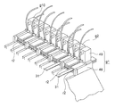
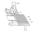
図1は本発明の実施の形態における刃切断装置の概念図、図3は本発明の実施の形態における刃切断装置の斜視図、図4は本発明の実施の形態における刃切断装置の側面図、図5は本発明の実施の形態における刃切断装置の平面図、図6は本発明の実施の形態における刃切断装置の背面図、図7は本発明の実施の形態における帯状材料案内部の斜視図、図8は本発明の実施の形態における帯状材料案内部の要部斜視図、図9は本発明の実施の形態における刃収容部の斜視図、図10は本発明の実施の形態における刃切断装置の機構図である。
図において、30は刃切断装置、31は、打抜刃26(図2)、罫線刃27等の刃の資材である帯状材料、32は、フレームFr1に対して矢印A、B方向に移動自在に配設され、帯状材料31を収容する資材収容部、33は、フレームFr2に固定され、帯状材料31を所定の長さに切断して刃を形成するための帯状材料加工部、34は、フレームFr2に対して矢印C、D方向に移動自在に配設され、前記帯状材料加工部33において切断することによって形成された刃を収容する刃収容部、M1は前記資材収容部32を矢印A、B方向に移動させるための駆動部としてのモータ、M2は前記刃収容部34を矢印C、D方向に移動させるための駆動部としてのモータである。モータM1、M2は同期させて駆動され、モータM1、M2がいずれも正方向に駆動されると、資材収容部32は矢印A方向に、刃収容部34は矢印C方向に移動させられ、モータM1、M2がいずれも逆方向に駆動されると、資材収容部32は矢印B方向に、刃収容部34は矢印D方向に移動させられる。
前記資材収容部32は、互いに平行に延在させて立設された複数の、本実施の形態においては、11個の、「U」字状の形状を有する区画壁waを備え、該区画壁waによって複数の、本実施の形態においては、10個の収容室Ri(i=1、2、…、10)が形成される。各収容室Riには、巻回された状態の帯状材料31、すなわち、ロール(コイル
)Crが種類ごとに分けて収容される。
)Crが種類ごとに分けて収容される。
ところで、前記帯状材料31は、資材収容部32にロールCrの状態で収容されるので、資材収容部32から引き出されると、巻き癖が付いている。そこで、本実施の形態においては、前記資材収容部32における帯状材料加工部33側の端部に、各収容室Riから引き出された帯状材料31を取り込み、搬送して資材収容部32に案内するとともに、その間に、帯状材料31に付いた巻き癖を取る帯状材料案内部41が配設される。
該帯状材料案内部41は、刃切断装置30の幅方向に延在させて配設されるとともに、各収容室Riに対応させて複数の、本実施の形態においては、10個の取込口としての穴hi(i=1、2、…、10)が並列に形成された取込板材43、帯状材料31の搬送方向における取込板材43より上流側において、各穴hiに臨ませて、取込板材43に対して上下方向に移動自在に配設され、帯状材料案内部41への帯状材料31の取込み位置を調整する複数の、本実施の形態においては、10個の位置調整部di(i=1、2、…、10)、帯状材料31の搬送方向における取込板材43より下流側において、各穴hiと対応させて回転自在に配設され、帯状材料31を上方から押すことによって帯状材料31の搬送方向を下方に向ける10個の押付部材としてのローラr1、帯状材料31の搬送方向におけるローラr1より下流側において、各ローラr1と対応させて回転自在に配設され、帯状材料31を下方から押すことによって帯状材料31を支持する10個の第1の支持部材としてのローラr2、及び前記各収容室Riと対応させて、かつ、各ローラr2と隣接させて配設され、帯状材料31を待機位置に置いたり、帯状材料加工部33に案内したりするための複数の、本実施の形態においては、10個のゲート部gi(i=1、2、…、10)を備える。
前記位置調整部di(i=1、2、…、10)は、取込板材43に対して上下方向に移動自在に配設された移動支持部材としてのバー45、該バー45の上端において回転自在に配設され、高さ方向における所定の位置において帯状材料31を下方から押すことによって帯状材料31を支持する10個の第2の支持部材としてのローラr3、前記バー45の下端に当接させて、取込板材43に対して回転自在に、かつ、上下方向に移動自在に配設された位置調整要素としてのねじ46、及び該ねじ46の下端に配設された操作要素としての摘み47を備える。したがって、刃切断装置30の操作者が前記摘み47を回転させてねじ46を回転させ、バー45及びローラr3を上下方向に移動させることによって、ローラr3の位置を調整することができる。
なお、前記取込板材43には、前記バー45を貫通させる穴を備え、バー45を移動自在に保持する保持部材43a、43b、及び前記ねじ46と螺合させられるねじ穴を備え、ねじ46を回転自在に、かつ、移動自在に保持する保持部材43cが突出させて形成される。
ところで、前記各ローラr1~r3は帯状材料31の搬送方向に沿って配設され、前記各ローラr1は回転しながら帯状材料31を上方から押し、各ローラr2、r3は回転しながら帯状材料31を下方から押すので、帯状材料31が搬送される間に、帯状材料31に付いた巻き癖を取ることができる。
また、帯状材料31の種類、例えば、材質、厚さ、幅等によって、帯状材料31に付く巻き癖の強さは異なるが、操作者が位置調整部diを操作し、ローラr3を巻き癖の強さに応じて所定の位置に置くと、取込み高さが調整されるので、帯状材料31に付いた巻き癖を帯状材料31の種類に応じて確実に取ることができる。なお、前記ローラr1~r3によって、帯状材料31に付いた巻き癖を取るための巻き癖解消部が構成される。また、本実施の形態においては、ローラr1~r3のうちのローラr3の位置が調整されるよう
になっているが、ローラr1、r2のうちのいずれか一方の位置を調整することによって、帯状材料31に付いた巻き癖を帯状材料31の種類に応じて取ることができる。
になっているが、ローラr1、r2のうちのいずれか一方の位置を調整することによって、帯状材料31に付いた巻き癖を帯状材料31の種類に応じて取ることができる。
前記各ゲート部giは、帯状材料31の搬送方向におけるローラr1より下流側において、各帯状材料31を待機位置に置いたり、所定の収容室Riから引き出された帯状材料31を選択して帯状材料加工部33に案内したりする。
そのために、各ゲート部giは、帯状材料31の搬送路を開閉するゲート48、及び該ゲート48を駆動するためのアクチュエータとしてのエアシリンダ49を備え、前記各ゲート48は、上下方向において接離自在に配設された一対の挟持部材としてのプレート48a、48bを備える。そして、前記各エアシリンダ49は、ゲート部giに対応させて配設された複数の、本実施の形態においては、10個の切換弁Vi(i=1、2、…、10)を介して媒体供給源としての圧縮機Cと接続され、圧縮機Cから送られた作動媒体としての圧縮空気を受け、ゲート48を駆動し、プレート48aを上下方向に移動させる。
プレート48aが、上位置に置かれ、プレート48bから離間させられると、帯状材料31の搬送路が開かれ、帯状材料31を搬送することができるようになる。また、プレート48aが、下位置に置かれ、プレート48bと当接させられると、帯状材料31の搬送路が閉じられ、帯状材料31がプレート48a、48bによって挟持され、搬送されなくなる。このとき、帯状材料31は待機位置に置かれる。待機位置に置かれた各帯状材料31はプレート48a、48bによって挟持されるので、刃切断装置30に発生する振動、自重等によって帯状材料31が待機位置からずれた位置に移動するのを防止することができる。
前記帯状材料加工部33は、帯状材料31の搬送方向における上流側の端部において、各ゲート部giのうちの一つと対向させて配設され、所定の収容室Riから引き出され、ゲート部giにおいて選択されて案内された一つの帯状材料31を搬送する第1の搬送ユニット51、帯状材料31の搬送方向における第1の搬送ユニット51より下流側に配設され、帯状材料31を搬送する第2の搬送ユニット52、第1、第2の搬送ユニット51、52間において第2の搬送ユニット52に隣接させて配設され、帯状材料31の搬送量を検出する搬送量検出部としてのエンコーダ53、帯状材料31の搬送方向における第2の搬送ユニット52より下流側において、第2の搬送ユニット52に隣接させて配設され、帯状材料31を所定の長さに切断して刃を形成する切断ユニット55、該切断ユニット55によって形成された刃を刃収容部34に送る排出部としてのシュート57、第1、第2の搬送ユニット51、52間において第1の搬送ユニット51に隣接させて配設され、帯状材料31の位置を検出する位置検出部としての帯状材料センサ65等を備える。
前記第1の搬送ユニット51は、帯状材料31を挟持することによって搬送する挟持搬送部61、及び該挟持搬送部61を駆動するためのアクチュエータとしてのエアシリンダ62を備える。前記挟持搬送部61は、回転自在に、かつ、上下方向において接離自在に配設された一対の搬送部材としてのローラr11、r12、並びに該ローラr11、r12のうちの一方のローラ、本実施の形態においては、ローラr12を正方向及び逆方向に回転させるための搬送用の駆動部としてのモータM3を備える。そして、前記エアシリンダ62は、切換弁Vaを介して圧縮機Cと接続され、圧縮機Cから送られた圧縮空気を受け、挟持搬送部61を駆動し、ローラr11を上下方向に移動させる。
ローラr11が上位置に置かれ、ローラr12から離間させられると、帯状材料31の搬送路が開かれ、帯状材料31が搬送されなくなる。また、ローラr11が下位置に置かれると、帯状材料31の搬送路が閉じられ、帯状材料31が搬送される。そして、帯状材料31は、モータM3が正方向に駆動されると、第2の搬送ユニット52に向けて前進さ
せられ、モータM3が逆方向に駆動されると、後退させられる。
せられ、モータM3が逆方向に駆動されると、後退させられる。
なお、各ゲート部giにおいて帯状材料31が待機位置に置かれると、プレート48aが下位置に置かれ、帯状材料31はプレート48a、48bによって挟持され、第1の搬送ユニット51において、ローラr11は上位置に置かれ、帯状材料31の搬送路が開かれる。このとき、帯状材料31の先端31aは、ローラr11、r12が互いに当接する位置よりわずかに第2の搬送ユニット52側に突出させられる。
前記第2の搬送ユニット52は、帯状材料31を挟持することによって搬送する挟持搬送部64を備える。該挟持搬送部64は、回転自在に配設された一対の搬送部材としてのローラr13、r14、並びに該ローラr13、r14のうちの一方のローラ、本実施の形態においては、ローラr13を正方向及び逆方向に回転させるための搬送用の駆動部としてのモータM4を備える。
そして、前記エンコーダ53は、第1、第2の搬送ユニット51、52によって帯状材料31が搬送されると、帯状材料31の搬送量を検出する。
また、前記切断ユニット55は、帯状材料31を切断するための金型56、該金型56を駆動するための切断用の駆動部としてのモータM5、及び該モータM5の回転運動を往復運動に変換する運動方向変換部58を備える。前記金型56は雄型56a及び雌型56bを備え、前記運動方向変換部58は、モータM5の出力軸sh1と螺合させられた回転伝達軸sh2、及び該回転伝達軸sh2によって回転させられるカム58aを備え、モータM5が駆動され、出力軸sh1が回転させられると、回転伝達軸sh2を介してカム58aが回転させられ、雄型56aが上下方向に移動させられる。該雄型56aは、上位置において雌型56bから離間させられ、下位置において雌型56b内に進入し、帯状材料31を切断する。
そして、前記刃収容部34は、互いに平行に延在させて立設された複数の、本実施の形態においては、11個の区画壁wbを備え、該各区画壁wbによって複数の、本実施の形態においては、10個の溝状の収容室Si(i=1、2、…、10)が形成される。各収容室Siには、前記切断ユニット55において帯状材料31を切断することによって形成された刃が種類ごとに分けて収容される。
次に、刃切断装置30の制御装置について説明する。
図11は本発明の実施の形態における刃切断装置の制御ブロック図である。
図において、71は刃切断装置30の全体の制御を行う制御部、72は記憶装置としてのメモリ、73は操作パネル等から成る操作部、74は、液晶パネル、ディスプレイ等から成る表示部である。また、76は各モータM1~M5を駆動するモータ駆動部、53はエンコーダ、65は帯状材料センサ、77は、切換弁Vi、Vaを切り換えることによってエアシリンダ49、62を駆動する空圧制御部である。
前記エンコーダ53は、ロータリエンコーダから成り、帯状材料31(図1)を挟持し、帯状材料31が搬送されるのに伴って、帯状材料31との摩擦によって回転させられる一対の回転体を備え、該回転体の回転角度に基づいて帯状材料31の搬送量を検出し、検出信号を制御部71に送る。
ところで、本実施の形態においては、モータM4の回転角度に基づいて帯状材料31の搬送量が検出されるようになっているが、帯状材料31はロールCrを巻き戻しながら引
き出されるので、第2の搬送ユニット52によって帯状材料31を搬送する際にモータM4に大きな負荷が加わり、帯状材料31がスリップして円滑に搬送することができないことがある。その場合、モータM4の回転角度に基づいて帯状材料31の搬送量を精度よく検出することができなくなるが、本実施の形態においては、エンコーダ53がモータM4と別に配設され、帯状材料31との摩擦によって回転させられる回転体の回転角度に基づいて帯状材料31の搬送量が検出されるので、帯状材料31の搬送量を精度よく検出することができる。
き出されるので、第2の搬送ユニット52によって帯状材料31を搬送する際にモータM4に大きな負荷が加わり、帯状材料31がスリップして円滑に搬送することができないことがある。その場合、モータM4の回転角度に基づいて帯状材料31の搬送量を精度よく検出することができなくなるが、本実施の形態においては、エンコーダ53がモータM4と別に配設され、帯状材料31との摩擦によって回転させられる回転体の回転角度に基づいて帯状材料31の搬送量が検出されるので、帯状材料31の搬送量を精度よく検出することができる。
前記帯状材料センサ65は、第1、第2の搬送ユニット51、52間を搬送される帯状材料31の位置を検出し、検出信号を制御部71に送る。なお、本実施の形態においては、帯状材料31の先端31aが挟持搬送部64のローラr13、r14間に到達したかどうかを、エンコーダ53のセンサ出力によって判断するようになっているが、帯状材料31の搬送方向における第2の搬送ユニット52より下流側において、第2の搬送ユニット52に隣接させて帯状材料センサを配設し、該帯状材料センサの検出信号に基づいて、帯状材料31の先端31aが挟持搬送部64のローラr13、r14間に到達したかどうかを判断することもできる。
次に、刃切断装置30の動作について説明する。
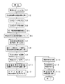
図12は本発明の実施の形態における刃切断装置の動作を示すフローチャートである。
まず、操作者が刃切断装置30の電源をオンにする(ステップS1)と、制御部71は刃切断装置30を初期状態に置く(ステップS2)。このとき、帯状材料案内部41において、各ゲート部giのゲート48が開かれ、プレート48aが上位置に置かれ、第1の搬送ユニット51において、挟持搬送部61のローラr11、r12が停止させられるとともに、ローラr11が上位置に置かれる。また、第2の搬送ユニット52において、挟持搬送部64のローラr13、r14が停止させられ、切断ユニット55において、金型56の雄型56aが上位置に置かれる。
次に、操作者が、刃切断装置30の操作部73(図11)を操作して、打抜機10(図2)による打抜きを行うために設計されたCADデータを刃切断装置30に入力する(ステップS3)と、制御部71は、CADデータを読み込み、メモリ72に記録する。続いて、制御部71は、メモリ72からCADデータを読み出して分析し(ステップS4)、刃の形状及び寸法を表す図形データを抽出し、該図形データに基づいて、打抜機10によって打抜きを行う際に必要となる刃の色、厚さ、長さ等を算出し、刃を形成するのに必要な帯状材料31を特定するとともに、刃の色、厚さ、長さ、各帯状材料31の名称等の刃・帯状材料情報をリストによって表示部74に表示する(ステップS5)。
そして、操作者は、表示部74に表示されたリストに従って、資材収容部32の各収容室Riに、帯状材料31のロールCrを帯状材料31の種類ごとに分けてセットし(ステップS6)、各帯状材料31を引き出し、帯状材料案内部41に取り込む(ステップS7)。このとき、帯状材料31の先端31aは、第1の搬送ユニット51のローラr11、r12が互いに当接する位置よりわずかに第2の搬送ユニット52側に突出させられる。
続いて、制御部71は、空圧制御部77に指示を送り、切換弁Viを切り換え、各エアシリンダ49を駆動し、ゲート48を閉じ、プレート48aを下位置に置く。これにより、各帯状材料31は、先端31aがローラr11、r12が当接する位置よりわずかに突出した状態で待機位置に置かれる(ステップS8)。
次に、操作者は、位置調整部diの摘み47を回転させることによってねじ46を回転
させ、バー45及びローラr3を上下方向に移動させ、ローラr3を、帯状材料31に付いた巻き癖の強さに応じて高さ方向における所定の位置に置き、取込み高さを調整する(ステップS9)。
させ、バー45及びローラr3を上下方向に移動させ、ローラr3を、帯状材料31に付いた巻き癖の強さに応じて高さ方向における所定の位置に置き、取込み高さを調整する(ステップS9)。
続いて、操作者が操作部73の開始ボタンを押下する(ステップS10)と、制御部71は、モータ駆動部76に指示を送り、モータM1、M2を駆動し、資材収容部32を移動させ、帯状材料31のロールCrが収容された所定の収容室Riを、帯状材料加工部33と対向する位置、すなわち、帯状材料加工位置に置くとともに、刃収容部34を移動させ、帯状材料31を切断することによって形成された刃が収容される所定の収容室Siを、帯状材料加工部33と対向する位置、すなわち、刃収容位置に置く(ステップS11)。
そして、制御部71は、空圧制御部77に指示を送り、切換弁Viを切り換えることによって、帯状材料加工位置に置かれた収容室Riに対応するゲート部giのゲート48を開き、プレート48aを上位置に置くとともに、切換弁Vaを切り換えることによって、第1の搬送ユニット51のローラr11を下位置に置く。また、制御部71は、モータ駆動部76に指示を送り、モータM3、M4を正方向に駆動し、ローラr11~r14を回転させる。これにより、帯状材料31が、第1、第2の搬送ユニット51、52によって搬送され、前進させられる(ステップS12)。
そして、帯状材料31の先端31aがエンコーダ53に到達すると、エンコーダ53は、帯状材料31の搬送量の検出を開始し、検出信号を制御部71に送る。
制御部71は、エンコーダ53から送られた検出信号に基づいて、前記帯状材料31の先端31aがローラr13、r14間に到達したかどうかを判断し、前記帯状材料31の先端31aがローラr13、r14間に到達したと判断すると、空圧制御部77に指示を送り、切換弁Vaを切り換えることによってローラr11を上位置に置くとともに、モータ駆動部76に指示を送り、モータM3の駆動を停止させる。したがって、帯状材料31が第2の搬送ユニット52によって搬送される間、挟持搬送部61による負荷が第2の搬送ユニット52に加わらないので、帯状材料31を安定させて搬送することができる。その結果、刃を精度よく形成することができる。
また、制御部71は、エンコーダ53から送られた検出信号に基づいて、帯状材料31の搬送量を取得し、該搬送量が、形成される刃の長さと等しくなると、モータ駆動部76に指示を送り、モータM5を駆動し、金型56によって帯状材料31を切断する(ステップS13)。
そして、帯状材料31を切断することによって形成された刃は、シュート57を介して刃収容位置に置かれた収容室Siに排出される。
続いて、制御部71は、モータ駆動部76に指示を送り、モータM3、M4を逆方向に駆動し、ローラr11~r14を逆方向に回転させる。これにより、切断された後の帯状材料31が、第1、第2の搬送ユニット51、52によって搬送され、後退させられる(ステップS14)。
そして、帯状材料センサ65が、帯状材料31の先端31aを検出し、検出信号を制御部71に送ると、制御部71は、モータ駆動部76に指示を送り、モータM3、M4の駆動を停止させる。また、制御部71は、空圧制御部77に指示を送り、切換弁Viを切り換えることによって、ゲート部giのゲート48を閉じ、プレート48aを下位置に置くとともに、空圧制御部77に指示を送り、切換弁Vaを切り換えることによって、第1の
搬送ユニット51において、挟持搬送部61のローラr11を上位置に置く。このようにして、帯状材料31が待機位置に置かれる(ステップS15)。
搬送ユニット51において、挟持搬送部61のローラr11を上位置に置く。このようにして、帯状材料31が待機位置に置かれる(ステップS15)。
本実施の形態においては、図1に示されるように、資材収容部32の収容室R1、R3に帯状材料31のロールCrがセットされ、収容室R1、R3から引き出された帯状材料31の先端31aが、第1の搬送ユニット51のローラr11、r12(図4)が互いに当接する位置よりわずかに第2の搬送ユニット52側に突出させられて、帯状材料31が待機位置に置かれる。
そして、操作者が操作部73(図11)の開始ボタンを押下すると、モータM1、M2が駆動され、資材収容部32の収容室R3が帯状材料加工位置に置かれ、刃収容部34の収容室S3が刃収容位置に置かれる。
続いて、帯状材料案内部41において、帯状材料加工位置に置かれた収容室R3に対応するゲート部g3のゲート48が開かれ、プレート48aが上位置に置かれ、帯状材料加工部33において、挟持搬送部61のローラr11が下位置に置かれ、モータM3、M4が正方向に駆動され、ローラr11~r14が回転させられる。これにより、収容室R3から引き出された帯状材料31が、第1、第2の搬送ユニット51、52によって搬送され、前進させられる。
帯状材料31の先端31aがエンコーダ53に到達すると、エンコーダ53によって帯状材料31の搬送量の検出が開始され、帯状材料31の搬送量が刃の長さと等しくなると、モータM5が駆動され、金型56によって帯状材料31が図形データにおいて規定された寸法に切断される。そして、切断することによって形成された刃は、シュート57を介して刃収容位置に置かれた収容室S3に排出される。
続いて、モータM3、M4が逆方向に駆動され、ローラr11~r14が回転させられ、帯状材料31が、第1、第2の搬送ユニット51、52によって搬送され、後退させられる。そして、帯状材料センサ65が帯状材料31の先端31aを検出すると、モータM3、M4が停止させられ、ローラr11~r14が停止させられ、ゲート部g3のゲート48が閉じられ、帯状材料31が待機位置に置かれる。
このように、本実施の形態においては、帯状材料31が、種類ごとに分けられて資材収容部32の複数の収容室Riにセットされ、複数の収容室Riのうちの所定の収容室が帯状材料加工部33と対向する帯状材料加工位置に置かれ、所定の収容室から引き出された帯状材料31が、第1、第2の搬送ユニット51、52によって搬送され、切断ユニット55によって所定の長さに切断されて刃が形成される。
したがって、多くの種類の帯状材料31から刃を形成するのに必要な帯状材料31を選択する作業を簡素化することができ、しかも、刃を精度よく形成することができる。
また、刃収容部34の複数の収容室Siのうちの所定の収容室が帯状材料加工部33と対向する刃収容位置に置かれ、切断ユニット55によって形成された刃が所定の収容室に排出されるので、帯状材料31に応じた刃を種類ごとに分けて収容することができる。
したがって、各収容室Siから取り出した刃を打抜型の溝に正しく埋め込むことができるので、ブランクを正確に成形することができる。
本実施の形態においては、資材収容部32と刃収容部34との間に、所定の数の、本実施の形態においては、一つの帯状材料加工部33が配設されるようになっているが、資材
収容部32と刃収容部34との間に複数の、例えば、二つの帯状材料加工部33を並列に配設することができる。その場合、帯状材料案内部41に取り込まれた各帯状材料31のうちの二つが選択されて帯状材料加工部33に案内される。
収容部32と刃収容部34との間に複数の、例えば、二つの帯状材料加工部33を並列に配設することができる。その場合、帯状材料案内部41に取り込まれた各帯状材料31のうちの二つが選択されて帯状材料加工部33に案内される。
また、本実施の形態においては、前記アクチュエータとしてエアシリンダ49、62が使用されるようになっているが、エアシリンダ49、62に代えて、油圧シリンダ、モータ等を使用することができる。
26 打抜刃
27 罫線刃
30 刃切断装置
31 帯状材料
32 資材収容部
33 帯状材料加工部
51、52 第1、第2の搬送ユニット
55 切断ユニット
71 制御部
Ri 収容室
27 罫線刃
30 刃切断装置
31 帯状材料
32 資材収容部
33 帯状材料加工部
51、52 第1、第2の搬送ユニット
55 切断ユニット
71 制御部
Ri 収容室
Claims (10)
- (a)刃を形成するための資材である帯状材料を種類ごとに分けて収容するための複数の収容室を備えた資材収容部と、
(b)前記複数の収容室のうちの所定の収容室から引き出された帯状材料を搬送する搬送ユニット、及び搬送された帯状材料を所定の長さに切断して刃を形成する切断ユニットを備えた帯状材料加工部と、
(c)前記資材収容部を移動させ、資材収容部の所定の収容室を前記帯状材料加工部と対向する位置に置く制御部とを有することを特徴とする刃切断装置。 - (a)切断された刃を種類ごとに分けて収容するための複数の収容室を備えた刃収容部を有するとともに、
(b)前記制御部は、前記刃収容部を移動させ、刃収容部の所定の収容室を前記帯状材料加工部と対向する位置に置く請求項1に記載の刃切断装置。 - 前記資材収容部は、資材収容部の各収容室から引き出された帯状材料を取り込み、搬送するとともに、帯状材料に付いた巻き癖を取る帯状材料案内部を備える請求項2に記載の刃切断装置。
- 前記帯状材料案内部は、前記資材収容部の各収容室に対応させて配設され、帯状材料に付いた巻き癖を取るための巻き癖解消部を備える請求項3に記載の刃切断装置。
- 前記各巻き癖解消部は、帯状材料の搬送方向に沿って配設された複数のローラから成る請求項4に記載の刃切断装置。
- 前記帯状材料案内部は、複数のローラのうちの所定のローラの位置を調整する位置調整部を備える請求項5に記載の刃切断装置。
- 前記帯状材料案内部は、前記資材収容部の各収容室に対応させて配設され、各収容室から引き出された帯状材料を挟持し、待機位置に置くためのゲート部を備える請求項3に記載の刃切断装置。
- (a)前記帯状材料加工部は、前記搬送ユニットによって搬送される帯状材料の搬送量を検出する搬送量検出部を備え、
(b)前記制御部は、搬送量検出部によって検出された搬送量が刃の長さと等しくなった場合に、前記切断ユニットによって帯状材料を切断する請求項1に記載の刃切断装置。 - 前記制御部は、切断された後の帯状材料を搬送ユニットによって後退させ、待機位置に置く請求項8に記載の刃切断装置。
- (a)刃を形成するための資材である帯状材料を、資材収容部の複数の収容室に種類ごとに分けてセットし、
(b)前記資材収容部を移動させ、資材収容部の所定の収容室を、資材収容部と隣接させて配設された帯状材料加工部と対向する位置に置き、
(c)該帯状材料加工部において、資材収容部の複数の収容室のうちの所定の収容室から引き出された帯状材料を搬送し、帯状材料を所定の長さに切断して刃を形成することを特徴とする刃切断方法。
Priority Applications (3)
| Application Number | Priority Date | Filing Date | Title |
|---|---|---|---|
| PCT/JP2016/055461 WO2017145291A1 (ja) | 2016-02-24 | 2016-02-24 | 刃切断装置及び刃切断方法 |
| US16/078,226 US10953456B2 (en) | 2016-02-24 | 2016-02-24 | Blade cutting device and blade cutting method |
| JP2017525639A JP6392989B2 (ja) | 2016-02-24 | 2016-02-24 | 刃切断装置及び刃切断方法 |
Applications Claiming Priority (1)
| Application Number | Priority Date | Filing Date | Title |
|---|---|---|---|
| PCT/JP2016/055461 WO2017145291A1 (ja) | 2016-02-24 | 2016-02-24 | 刃切断装置及び刃切断方法 |
Publications (1)
| Publication Number | Publication Date |
|---|---|
| WO2017145291A1 true WO2017145291A1 (ja) | 2017-08-31 |
Family
ID=59685941
Family Applications (1)
| Application Number | Title | Priority Date | Filing Date |
|---|---|---|---|
| PCT/JP2016/055461 Ceased WO2017145291A1 (ja) | 2016-02-24 | 2016-02-24 | 刃切断装置及び刃切断方法 |
Country Status (3)
| Country | Link |
|---|---|
| US (1) | US10953456B2 (ja) |
| JP (1) | JP6392989B2 (ja) |
| WO (1) | WO2017145291A1 (ja) |
Cited By (1)
| Publication number | Priority date | Publication date | Assignee | Title |
|---|---|---|---|---|
| JP2021176649A (ja) * | 2020-05-09 | 2021-11-11 | 嘉興市華鼎保温技術有限公司 | プレス加工装置 |
Families Citing this family (2)
| Publication number | Priority date | Publication date | Assignee | Title |
|---|---|---|---|---|
| DE102017205095B3 (de) * | 2017-03-27 | 2018-06-28 | Trumpf Werkzeugmaschinen Gmbh + Co. Kg | Vorrichtung und Verfahren zum Entnehmen eines Werkstückteils aus einem Restwerkstück |
| SG10201704185YA (en) * | 2017-05-23 | 2018-12-28 | Hock Hai Low | Method of aligning a flat or profiled metal sheet |
Citations (4)
| Publication number | Priority date | Publication date | Assignee | Title |
|---|---|---|---|---|
| JPH1058042A (ja) * | 1996-08-21 | 1998-03-03 | Tsukatani Hamono Seisakusho:Kk | 帯刃の曲げ加工装置 |
| JP2001314932A (ja) * | 2000-02-28 | 2001-11-13 | Santekusu Kk | 帯刃加工装置及び加工方法 |
| JP2003326331A (ja) * | 2002-05-15 | 2003-11-18 | Rezakku:Kk | 帯刃加工装置 |
| JP2005230883A (ja) * | 2004-02-20 | 2005-09-02 | Bridgestone Corp | 自動プレス装置 |
Family Cites Families (6)
| Publication number | Priority date | Publication date | Assignee | Title |
|---|---|---|---|---|
| US4474092A (en) * | 1983-04-21 | 1984-10-02 | Oscar Mayer Foods Corp. | Product storage bank and merge system |
| US4571810A (en) * | 1984-01-27 | 1986-02-25 | Trumpf America, Inc. | Installation comprising automatic machine tooling and sorting apparatus |
| JP3282983B2 (ja) * | 1997-01-17 | 2002-05-20 | 京セラミタ株式会社 | パンチ屑回収報知機能付き装置 |
| EP1354648B1 (de) * | 2002-04-17 | 2005-05-11 | Mabi Ag | Einrichtung zum Bearbeiten von Blech |
| JP4931021B2 (ja) | 2008-09-03 | 2012-05-16 | 学校法人近畿大学 | 太陽熱蒸留装置 |
| US8419415B2 (en) * | 2010-11-05 | 2013-04-16 | Ykk Corporation | Systems and methods of feeding hook fastening elements into a mold assembly line |
-
2016
- 2016-02-24 US US16/078,226 patent/US10953456B2/en active Active
- 2016-02-24 WO PCT/JP2016/055461 patent/WO2017145291A1/ja not_active Ceased
- 2016-02-24 JP JP2017525639A patent/JP6392989B2/ja active Active
Patent Citations (4)
| Publication number | Priority date | Publication date | Assignee | Title |
|---|---|---|---|---|
| JPH1058042A (ja) * | 1996-08-21 | 1998-03-03 | Tsukatani Hamono Seisakusho:Kk | 帯刃の曲げ加工装置 |
| JP2001314932A (ja) * | 2000-02-28 | 2001-11-13 | Santekusu Kk | 帯刃加工装置及び加工方法 |
| JP2003326331A (ja) * | 2002-05-15 | 2003-11-18 | Rezakku:Kk | 帯刃加工装置 |
| JP2005230883A (ja) * | 2004-02-20 | 2005-09-02 | Bridgestone Corp | 自動プレス装置 |
Cited By (1)
| Publication number | Priority date | Publication date | Assignee | Title |
|---|---|---|---|---|
| JP2021176649A (ja) * | 2020-05-09 | 2021-11-11 | 嘉興市華鼎保温技術有限公司 | プレス加工装置 |
Also Published As
| Publication number | Publication date |
|---|---|
| JP6392989B2 (ja) | 2018-09-19 |
| US20190022734A1 (en) | 2019-01-24 |
| US10953456B2 (en) | 2021-03-23 |
| JPWO2017145291A1 (ja) | 2018-03-01 |
Similar Documents
| Publication | Publication Date | Title |
|---|---|---|
| AU735315B2 (en) | High speed web machine | |
| JP6392989B2 (ja) | 刃切断装置及び刃切断方法 | |
| CN102806782B (zh) | 带切断装置、带打印装置以及步进电机的控制方法 | |
| CA2197179A1 (en) | Apparatus for forming sheets of material having a uniform thickness and cutting individual portions therefrom | |
| NO751921L (ja) | ||
| JPS63295197A (ja) | 用紙の駆動・切断装置 | |
| EP3281801A1 (en) | Media conveyor mechanism for printing apparatus and method of mounting conveyor belt | |
| JPWO2019117286A1 (ja) | 段ボール箱の分割装置及び段ボール箱の製造装置 | |
| EP3056458B1 (en) | Rewinding machine | |
| CN107414921A (zh) | 一种标签感应剪切装置 | |
| JP7165290B2 (ja) | アルミロール端面揃え装置 | |
| CN110271885A (zh) | 烫金模切流水线设备 | |
| JP7335605B2 (ja) | 打ち抜き装置、定盤間平行調整方法及び定盤間平行調整部材 | |
| JP4207616B2 (ja) | 裁断装置 | |
| JP6151392B1 (ja) | 結束バンド処理装置および結束バンド処理方法 | |
| KR101595091B1 (ko) | 편심 구동형 톰슨프레스 | |
| CN102066088B (zh) | 塑料薄膜延伸装置 | |
| JP6022361B2 (ja) | 用紙筋入装置 | |
| JP3000506B2 (ja) | 打抜き機 | |
| JPH03190634A (ja) | 帯状シートの加工装置 | |
| US6382096B2 (en) | Stencil sheet retaining device | |
| CN208020710U (zh) | 曲面保护膜模具自动化生产设备 | |
| JP2022145060A (ja) | 加工処理システム | |
| KR100394789B1 (ko) | 철판용 가공장치 | |
| CN214394441U (zh) | 一种分切机张紧装置 |
Legal Events
| Date | Code | Title | Description |
|---|---|---|---|
| ENP | Entry into the national phase |
Ref document number: 2017525639 Country of ref document: JP Kind code of ref document: A |
|
| NENP | Non-entry into the national phase |
Ref country code: DE |
|
| 121 | Ep: the epo has been informed by wipo that ep was designated in this application |
Ref document number: 16891448 Country of ref document: EP Kind code of ref document: A1 |
|
| 122 | Ep: pct application non-entry in european phase |
Ref document number: 16891448 Country of ref document: EP Kind code of ref document: A1 |