WO2017145355A1 - Dispositif de bobine d'allumage pour moteur à combustion interne - Google Patents
Dispositif de bobine d'allumage pour moteur à combustion interne Download PDFInfo
- Publication number
- WO2017145355A1 WO2017145355A1 PCT/JP2016/055804 JP2016055804W WO2017145355A1 WO 2017145355 A1 WO2017145355 A1 WO 2017145355A1 JP 2016055804 W JP2016055804 W JP 2016055804W WO 2017145355 A1 WO2017145355 A1 WO 2017145355A1
- Authority
- WO
- WIPO (PCT)
- Prior art keywords
- iron core
- coil
- secondary coil
- internal combustion
- combustion engine
- Prior art date
- Legal status (The legal status is an assumption and is not a legal conclusion. Google has not performed a legal analysis and makes no representation as to the accuracy of the status listed.)
- Ceased
Links
Images



Classifications
-
- H—ELECTRICITY
- H01—ELECTRIC ELEMENTS
- H01F—MAGNETS; INDUCTANCES; TRANSFORMERS; SELECTION OF MATERIALS FOR THEIR MAGNETIC PROPERTIES
- H01F27/00—Details of transformers or inductances, in general
- H01F27/02—Casings
- H01F27/022—Encapsulation
-
- H—ELECTRICITY
- H01—ELECTRIC ELEMENTS
- H01F—MAGNETS; INDUCTANCES; TRANSFORMERS; SELECTION OF MATERIALS FOR THEIR MAGNETIC PROPERTIES
- H01F38/00—Adaptations of transformers or inductances for specific applications or functions
- H01F38/12—Ignition, e.g. for IC engines
-
- H—ELECTRICITY
- H01—ELECTRIC ELEMENTS
- H01F—MAGNETS; INDUCTANCES; TRANSFORMERS; SELECTION OF MATERIALS FOR THEIR MAGNETIC PROPERTIES
- H01F27/00—Details of transformers or inductances, in general
- H01F27/28—Coils; Windings; Conductive connections
- H01F27/32—Insulating of coils, windings, or parts thereof
- H01F27/327—Encapsulating or impregnating
-
- H—ELECTRICITY
- H01—ELECTRIC ELEMENTS
- H01F—MAGNETS; INDUCTANCES; TRANSFORMERS; SELECTION OF MATERIALS FOR THEIR MAGNETIC PROPERTIES
- H01F38/00—Adaptations of transformers or inductances for specific applications or functions
- H01F38/12—Ignition, e.g. for IC engines
- H01F2038/127—Ignition, e.g. for IC engines with magnetic circuit including permanent magnet
Definitions
- the present invention mainly relates to an ignition coil device which is attached to an internal combustion engine for a vehicle, for example, an internal combustion engine of an automobile, and generates a spark discharge by supplying a high voltage to an ignition plug.
- An ignition coil device for an internal combustion engine is configured, for example, by winding a primary coil and a secondary coil around the outer periphery of a center iron core (center core) and arranging a side iron core (outer core) outside the coil.
- These components are housed in an insulating case, and the space in the case is filled with an insulating resin or the like to maintain insulation.
- Electric field concentration and thermal stress concentration occur at the split end of the side iron core and the split end of the elastomer material, which may result in a decrease in insulation due to the electric field concentration, or a decrease in insulation due to peeling or cracking due to stress concentration.
- the structure in which the periphery of the side iron core is covered with an elastomer material is effective in reducing thermal stress, but the voltage resistance characteristic of the elastomer material itself is lower than that of an insulating filler such as an insulating resin.
- the boundary surface between the secondary bobbin around which the secondary coil is wound and the insulating resin has a lower withstand voltage than the insulating resin or the secondary bobbin.
- the present invention has been proposed in view of the above, and is an ignition for an internal combustion engine that suppresses an increase in size and ensures insulation between the secondary coil and the side iron core without lowering the insulation in the secondary coil.
- the purpose is to obtain a coil device.
- An ignition coil device for an internal combustion engine includes a primary coil wound around a cylindrical primary bobbin, and a cylindrical secondary bobbin having a plurality of flanges formed in parallel at intervals in the axial direction.
- a side iron core that is divided into a plurality of portions in the division part, an elastomer material that covers each of the divided side iron cores, and the center iron core, primary coil, secondary coil, side iron core, and elastomer material are accommodated.
- the side iron core and the elastomer material have a secondary coil side corner portion of a split end portion which is an end portion of the split portion side. Is set to be different from the arrangement position of the flange of the secondary bobbin in the axial direction of the secondary coil.
- the side iron core where the electric field and the stress are concentrated and the secondary coil side corner portion at the divided end portion of the elastomer material are separated from the flange portion of the secondary bobbin where the insulation property is lowered.
- the size of the secondary bobbin can be reduced without increasing the size of the flange of the secondary bobbin and the pressure resistance can be secured.
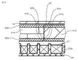
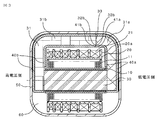
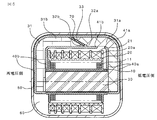
- FIG. 2 is an enlarged cross-sectional view showing a main part of FIG. It is principal part sectional drawing which shows the ignition coil apparatus for internal combustion engines of Embodiment 2 of this invention. It is principal part sectional drawing which shows the ignition coil apparatus for internal combustion engines of Embodiment 3 of this invention. It is principal part sectional drawing which shows the ignition coil apparatus for internal combustion engines of Embodiment 4 of this invention. It is an expanded sectional view which shows the principal part of FIG.
- FIG. 1 and 2 are a main part sectional view and an enlarged main part sectional view showing an ignition coil device for an internal combustion engine according to Embodiment 1 of the present invention.
- a primary coil 11 wound around a cylindrical primary bobbin 10 is provided in an insulating case 50.
- a cylindrical secondary bobbin 20 is provided outside the primary bobbin 10, and a secondary coil 21 is wound around the secondary bobbin 20.
- An I-type center iron core 30 passes through the center of the primary bobbin 10, and the primary coil 11 and the secondary coil 21 are disposed concentrically with respect to the center iron core 30.
- a side iron core 31 that forms a magnetic path together with the center iron core 30 forms a C-type side iron core divided into a plurality of parts, and is disposed so as to surround the primary coil 11 and the secondary coil 21.
- the side iron core 31 is covered with an elastomer material 40 such as a thermosetting or thermoplastic elastomer for the purpose of relieving thermal stress.
- An insulating resin 60 such as a thermosetting epoxy resin is injected into the insulating case 50 and then solidified.
- this ignition coil device is energized / interrupted in the primary coil 11 housed in the insulating case 50, for example, as in the ignition coil device disclosed in Japanese Patent Application Laid-Open No. 2010-27669.
- An igniter that performs the above operation, a low-pressure side connector that is provided integrally with the insulating case 50 and is electrically connected to the igniter, a high-pressure side connector that is electrically connected to the spark plug, and the like are provided.
- a drive signal from an external electronic control unit flows to the igniter via the low-voltage side connector, and controls energization and interruption of the primary current flowing to the primary coil 11.
- a secondary bobbin 20 around which a secondary coil 21 is wound has a plurality of flanges 20a (seven in the figure) made of an annular flat plate surrounding the outer periphery of a cylindrical base portion spaced apart from each other in the axial direction. A plurality of sections (six in the figure) are defined between adjacent flanges 20a.
- the secondary coil 21 is dividedly wound into sections sectioned by the flange 20a, and an insulation-coated copper wire having a predetermined wire diameter is wound a predetermined number of turns from one end side to the other end side in the axial direction. Is repeated.
- the secondary coil 21 has a low voltage side on the igniter side (right end side in FIG. 1) and a high voltage side on the other end side (left end side in FIG. 1).
- the side iron core 31 is divided into two side iron cores 31a and 31b by a dividing portion 33 formed in a direction parallel to the flange 20a of the secondary bobbin 20 at a portion facing the secondary coil 21.
- the side iron cores 31a and 31b are coated with elastomer materials 40a and 40b on substantially the entire outer periphery excluding the end face of the center iron core 30, respectively.
- Each of the side iron cores 31a, 31b and each of the elastomer materials 40a, 40b has a corner portion (hereinafter referred to as a secondary coil side corner portion) 32a facing the secondary coil 21 of the split end portion which is an end portion on the split portion 33 side.
- the positions of 32b, 41a, 41b are set near the middle of the third section of the secondary bobbin 20. Further, the corner portions 32a, 32b, 41a, 41b at the divided end portions of the side iron cores 31a, 31b and the elastomer materials 40a, 40b are formed to have an R shape (see FIG. 2).
- the ignition coil device for the internal combustion engine includes the side iron cores 31a and 31b divided into two parts and the divided end portions of the elastomer materials 40a and 40b covering the side iron cores 31a and 31b.
- the positions of the secondary coil side corner portions 32a, 32b, 41a, 41b are set near the middle of the third section of the secondary bobbin 20. For this reason, the secondary coil side corner portions 32a, 32b, 41a, 41b of the divided end portions of the side iron cores 31a, 31b and the elastomer materials 40a, 40b where the electric field and the thermal stress are concentrated are separated from the insulating resin 60.
- the insulation distance can be sufficiently secured away from the flange 20a of the secondary bobbin 20, which is inferior to that of the secondary bobbin 20, it is possible to ensure insulation while avoiding unnecessary enlargement.
- the corner portions 32a, 32b, 41a, 41b at the divided end portions of the side iron cores 31a, 31b and the elastomer materials 40a, 40b have an R shape, excessive electric field concentration and cold heat are generated at the corner portions. It is possible to prevent stress from being applied.
- the positions of the secondary coil side corner portions 32a, 32b of the side iron cores 31a, 31b and the secondary coil side corner portions 41a, 41b of the elastomer materials 40a, 40b are set to the positions of the secondary bobbin 20. Although it is in the vicinity of the middle of the section, if the positions of these corner portions 32a, 32b, 41a, 41b are set to be different from the arrangement position of the flange 20a of the secondary bobbin 20 in the axial direction of the secondary coil 21, It may be set between other sections.
- the positions of the secondary coil side corner portions 32a and 32b of the side iron cores 31a and 31b and the secondary coil side corner portions 41a and 41b of the elastomer materials 40a and 40b are set in the same section of the secondary bobbin 20. However, they may be set in different sections.
- the primary coil 11 wound around the cylindrical primary bobbin 10 and the plurality of flanges 20a are arranged in parallel at intervals in the axial direction.
- a cylindrical secondary bobbin 20 formed and a secondary coil 21 wound around a plurality of sections defined between the flanges 20a of the secondary bobbin 20 and concentrically disposed on the outer periphery of the primary coil 11.
- a center iron core 30 penetrating the primary bobbin 10 and arranged concentrically with the primary coil 11 and the secondary coil 21, and the primary coil 11 and the secondary coil so as to form a magnetic path together with the center iron core 30.
- Elastomer material that surrounds each of the side iron cores 31a and 31b that are divided into a plurality of divisions 33 and that surrounds each of the divided side iron cores 31a and 31b.
- the ignition coil device for an internal combustion engine that includes the iron cores 31a and 31b and the elastomer materials 40a and 40b and includes the insulating case 50 in which the insulating resin 60 is injected and hardened in the internal space, the side iron cores 31a and 31b and the elastomer materials
- the positions of the secondary coil side corner portions 32a, 32b, 41a, 41b of the split end portion, which is the end portion on the split portion 33 side, are the positions of the flange 20a of the secondary bobbin 20 in the axial direction of the secondary coil 21.
- the ignition coil device for an internal combustion engine configured in this way has a secondary iron side corner portion and a secondary coil side corner portion at the split end portion of the elastomer material where electric field and thermal stress are concentrated. Since a sufficient distance from the flange portion of the bobbin can be ensured, unnecessary insulation can be avoided and insulation can be ensured.
- FIG. FIG. 3 is a cross-sectional view of a main part showing the ignition coil device for an internal combustion engine according to the second embodiment of the present invention.
- 32b, 41a, 41b are set near the middle of the first section of the secondary bobbin 20.
- Other configurations are the same as those of the first embodiment.
- the electric field is concentrated on the secondary coil side corner portions 32a, 32b, 41a, 41b because the potential of the first section (low pressure side) of the secondary bobbin 20 is the lowest. Even in this case, the insulation resistance can be ensured without exceeding the withstand voltage of the insulating resin and without increasing the size.
- the secondary coil 21 can be secured from the flange 20a of the secondary bobbin 20 while ensuring the withstand voltage. It is also easy to secure the distance.
- FIG. FIG. 4 is a cross-sectional view of a main part showing an ignition coil device for an internal combustion engine according to Embodiment 3 of the present invention.
- the divided portion 33 of the side iron core 31 is an inclined side inclined with respect to the flange 20a of the secondary bobbin 20, and the secondary coil side corner portion 32a of each side iron core 31a, 31b. , 32b is set near the middle of the first section of the secondary bobbin 20.
- the position of the secondary coil side corner portion 41a in the divided end portion of the elastomer material 40a covering the side iron core 31a is located near the middle of the second section of the secondary bobbin 20, and the divided end portion of the elastomer material 40b covering the side iron core 31b.
- the position of the secondary coil side corner portion 41b is set near the middle of the third section of the secondary bobbin 20.
- the thickness of the elastomer material is set to about 0.5 mm to 1.5 mm, and each section width and flange thickness of the secondary bobbin 20 is set to 1.5 mm or more even on the narrowest high-pressure side.
- the thicknesses of the elastomer materials 40a and 40b are set to about 1.0 mm, and the secondary coil side corner portion 41a is set to the second section, and the secondary coil side corner portion 41b is set near the middle of the third section.
- the elastomer materials 40a and 40b have a distance between divisions of about 5.0 mm, and are configured to have a distance between divisions equal to or greater than the thickness of the elastomer materials 40a and 40b.
- Other configurations are the same as those of the first embodiment.
- the distance between the divided portions of the elastomer materials 40a and 40b covering the side iron cores 31a and 31b is at least equal to or greater than the thickness of the elastomer materials 40a and 40b.
- the insulating resin layer injected and cured between the elastomer materials can be prevented from becoming thin, the possibility of cracking in the insulating resin layer when applying a thermal stress is reduced, and the insulating property is reduced when applying a thermal stress. Can be prevented.
- the positions of the secondary coil side corner portions 31a, 31b, 41a, 41b of the divided end portions of the side iron cores 31a, 31b and the elastomer materials 40a, 40b are different from those of the secondary bobbin 20.
- the secondary bobbin with a narrow space between the sections the separation distance between the flange of the secondary bobbin, the divided ends of each side iron core, and the divided ends of each elastomer material is kept sufficiently even if a secondary bobbin with a narrow section is used. It is possible to suppress unnecessary enlargement and ensure durability.
- the gap length between the divided portions is the same level whether the cross section is vertical or inclined, whereas the cross sectional area of the magnetic circuit increases. An increase in magnetic resistance due to component variations can be suppressed.
- the divided portion 33 of the side iron core 31 is formed obliquely from the first section to the second section of the secondary bobbin 20, and the secondary coil side corner portion 41a of the divided end portion of the elastomer material 40a. Is set near the middle of the second section of the secondary bobbin 20, and the position of the secondary coil side corner 41b at the split end of the elastomer material 40b is set near the middle of the third section of the secondary bobbin 20. As long as the gap is formed between the divided end portions of the elastomer materials 40a and 40b, the position may be set at a position corresponding to another section.
- FIG. 5 and 6 are a main part sectional view and an enlarged main part sectional view showing an ignition coil device for an internal combustion engine according to a fourth embodiment of the present invention.
- the divided portion 33 of the side iron core 31 is an oblique side inclined from the second section to the third section of the secondary bobbin 20 with respect to the flange 20 a of the secondary bobbin 20.
- a magnet 70 for improving the magnetic efficiency is inserted between the divided portions 33 of the side iron core 31, and the edge portion 70a on the opposite side of the secondary coil of the magnet 70 is located further inside than the opposite surface of the side iron core 31a ( The side away from the secondary coil 21) (see FIG. 6).
- the positions of the secondary coil side corner portions 32a, 32b of the divided end portions of the side iron cores 31a, 31b are set in the vicinity of the middle of the second section of the secondary bobbin 20. Further, the position of the secondary coil side corner portion 41b of the divided end portion of the elastomer material 40b covering the side iron core 31a is set to the first section of the secondary bobbin 20, and the secondary coil side corner portion 41a of the divided end portion of the elastomer material 40a. Is located outside the wall surface of the low-pressure side section end of the secondary bobbin 20, and a large inter-division distance is secured with respect to the split end portions of the elastomer materials 40a and 40b.
- the angle of the secondary coil side corner portion 32b at the divided end portion of the side iron core 31b is set to be an acute angle as compared with the angle of the secondary coil side corner portion 32a at the divided end portion on the side iron core 31a side. Further, the entire periphery of the corners of the side iron core 31b and the magnet 70 is covered with an elastomer material 40b, and the assembly of the magnet 70 is surrounded by the elastomer material 40b. Other configurations are the same as those of the first embodiment.
- the edge portion 70a of the magnet 70 inserted between the divided portions 33 of the side iron core 31 is on the inner side (the side away from the secondary coil 21) from the side iron core surface.
- the magnet 70 does not protrude from the side iron core surface, and an insulation distance can be secured even when an electric field is concentrated on the edge portion of the magnet 70.
- the divided portion 33 of the side iron core 31 is the hypotenuse and the magnet 70 is inserted between the divided portions 33 of the side iron core 31, the cross-sectional area of the magnetic circuit is increased, resulting in component variations.
- the secondary coil side corner portions 32a and 32b of the divided end portions of the side iron cores 31a and 31b have an angle on the side iron core 31b side close to the high voltage side flange of the secondary bobbin 20, Compared with the angle on the side iron core 31a side near the low-voltage side flange of the secondary bobbin 20, the secondary coil side corner portion 32b on the acute angle side is on the secondary coil side corner portion on the obtuse angle side. It is arranged so that the distance from the flange 20a of the secondary bobbin 20 is slightly longer than 32a.
- the side iron core 31b on the acute angle side to which a larger electric field or thermal stress is applied, and the secondary whose insulation resistance is inferior A distance between the flanges 20a of the bobbin 20 can be secured. Further, since the entire corners of the side iron core 31b and the magnet 70 are covered with the elastomer material 40b, the thermal stress on the entire circumference of the side iron core 31b and the corners of the magnet 70 can be alleviated. In addition, since the elastomer material 40b surrounds the assembly surface of the magnet 70, the elastomer material 40b serves as a positioning when the magnet 70 is assembled, and the assemblability is improved. Moving to the side can also be prevented.
- the divided portion 33 of the side iron core 31 is formed obliquely from the second section to the third section of the secondary bobbin 20, and the secondary coil side corner portion 41b of the divided end portion of the elastomer material 40b. Is positioned near the middle of the first section of the secondary bobbin 20, and the corner 41a facing the secondary coil at the split end of the elastomer 40a is positioned outside the wall of the low-pressure section end of the secondary bobbin 20.
- the magnet does not protrude from the side iron core surface to the secondary coil side, the problem of insulation deterioration due to electric field concentration on the magnet and peeling or cracking due to thermal stress even with a configuration not covered with an elastomer material is Disappear. Further, if the elastomer material covers the magnet, the magnet can function to prevent misalignment with respect to the magnet. Therefore, there is no problem even if the division position of the elastomer material is in another section of the secondary bobbin.
Landscapes
- Engineering & Computer Science (AREA)
- Power Engineering (AREA)
- Ignition Installations For Internal Combustion Engines (AREA)
Abstract
Ce dispositif de bobine d'allumage pour un moteur à combustion interne comprend : des noyaux de fer latéraux (31a, 31b) entourant une bobine primaire (11) et une bobine secondaire (21) de manière à former un chemin magnétique avec un noyau de fer central (30), tout en étant divisés en une pluralité au niveau d'une partie de séparation (33) formée dans une partie faisant face à la bobine secondaire; des matériaux élastomères (40a, 40b), recouvrant chacun la périphérie des noyaux de fer latéraux respectifs divisés en la pluralité; et un boîtier isolant (50) logeant le noyau de fer central, la bobine primaire, la bobine secondaire, les noyaux de fer latéraux, et les matériaux élastomères, et ayant une résine isolante (60) injectée et durcie dans son espace interne. Chacun des noyaux de fer latéraux (31a, 31b) et chacun des matériaux élastomères (40a, 40b) sont réglés de telle manière que les positions, dans la direction axiale de la bobine secondaire, des parties de coin côté bobine secondaire (32a, 32b, 41a, 41b) au niveau des extrémités de division, qui sont les extrémités du côté partie de division, sont différentes de la position où est disposée une bride (20a) d'une bobine secondaire (20).
Priority Applications (5)
| Application Number | Priority Date | Filing Date | Title |
|---|---|---|---|
| PCT/JP2016/055804 WO2017145355A1 (fr) | 2016-02-26 | 2016-02-26 | Dispositif de bobine d'allumage pour moteur à combustion interne |
| CN201680081598.9A CN108701537B (zh) | 2016-02-26 | 2016-02-26 | 内燃机用点火线圈装置 |
| DE112016006501.9T DE112016006501T5 (de) | 2016-02-26 | 2016-02-26 | Zündspulenvorrichtung für Verbrennungsmotor |
| US15/771,587 US10438740B2 (en) | 2016-02-26 | 2016-02-26 | Ignition coil device for internal combustion engine |
| JP2018501524A JP6509424B2 (ja) | 2016-02-26 | 2016-02-26 | 内燃機関用点火コイル装置 |
Applications Claiming Priority (1)
| Application Number | Priority Date | Filing Date | Title |
|---|---|---|---|
| PCT/JP2016/055804 WO2017145355A1 (fr) | 2016-02-26 | 2016-02-26 | Dispositif de bobine d'allumage pour moteur à combustion interne |
Publications (1)
| Publication Number | Publication Date |
|---|---|
| WO2017145355A1 true WO2017145355A1 (fr) | 2017-08-31 |
Family
ID=59684905
Family Applications (1)
| Application Number | Title | Priority Date | Filing Date |
|---|---|---|---|
| PCT/JP2016/055804 Ceased WO2017145355A1 (fr) | 2016-02-26 | 2016-02-26 | Dispositif de bobine d'allumage pour moteur à combustion interne |
Country Status (5)
| Country | Link |
|---|---|
| US (1) | US10438740B2 (fr) |
| JP (1) | JP6509424B2 (fr) |
| CN (1) | CN108701537B (fr) |
| DE (1) | DE112016006501T5 (fr) |
| WO (1) | WO2017145355A1 (fr) |
Cited By (1)
| Publication number | Priority date | Publication date | Assignee | Title |
|---|---|---|---|---|
| US12576147B2 (en) | 2019-03-27 | 2026-03-17 | Inserm (Institut National De La Sante Et De La Recherche Medicale) | Recombinant proteins with CD40 activating properties |
Families Citing this family (2)
| Publication number | Priority date | Publication date | Assignee | Title |
|---|---|---|---|---|
| JP6648935B2 (ja) * | 2017-03-30 | 2020-02-14 | 三菱電機株式会社 | 点火コイル |
| JP7358839B2 (ja) * | 2019-08-22 | 2023-10-11 | 株式会社デンソー | 点火コイル |
Citations (5)
| Publication number | Priority date | Publication date | Assignee | Title |
|---|---|---|---|---|
| JPS60201607A (ja) * | 1984-03-26 | 1985-10-12 | Nippon Denso Co Ltd | 点火コイル |
| JPH10294228A (ja) * | 1997-04-18 | 1998-11-04 | Hanshin Electric Co Ltd | 内燃機関用点火コイル |
| JP2005019868A (ja) * | 2003-06-27 | 2005-01-20 | Hanshin Electric Co Ltd | 内燃機関用点火コイル |
| JP2006294914A (ja) * | 2005-04-12 | 2006-10-26 | Mitsubishi Electric Corp | 内燃機関用点火装置 |
| JP2012248645A (ja) * | 2011-05-27 | 2012-12-13 | Hitachi Automotive Systems Ltd | 内燃機関用点火コイル |
Family Cites Families (11)
| Publication number | Priority date | Publication date | Assignee | Title |
|---|---|---|---|---|
| ES2057622T3 (es) * | 1990-03-08 | 1994-10-16 | Nippon Denso Co | Bobina de encendido para un motor de combustion interna. |
| JP3229515B2 (ja) * | 1995-05-08 | 2001-11-19 | 三菱電機株式会社 | 内燃機関用点火装置 |
| JP3602267B2 (ja) * | 1996-07-12 | 2004-12-15 | 本田技研工業株式会社 | 点火コイル装置 |
| JP3727764B2 (ja) * | 1997-09-30 | 2005-12-14 | 株式会社日立製作所 | エンジン用点火コイル装置及びその製造方法 |
| JP3989073B2 (ja) * | 1998-01-07 | 2007-10-10 | 阪神エレクトリック株式会社 | 内燃機関の点火コイル |
| JP4658168B2 (ja) | 2008-07-15 | 2011-03-23 | 三菱電機株式会社 | 内燃機関用点火コイル装置、及びその製造方法 |
| CN201402734Y (zh) * | 2009-04-03 | 2010-02-10 | 楼甜甜 | 内部安装磁钢的点火线圈 |
| JP5846741B2 (ja) * | 2011-02-21 | 2016-01-20 | ダイヤモンド電機株式会社 | 内燃機関用の点火コイル |
| JP2013115075A (ja) * | 2011-11-25 | 2013-06-10 | Diamond Electric Mfg Co Ltd | 内燃機関用の点火コイル |
| JP6322978B2 (ja) | 2013-12-03 | 2018-05-16 | 株式会社デンソー | 内燃機関用点火コイル |
| CN204067016U (zh) * | 2014-09-30 | 2014-12-31 | 宁波市柏诺斯电器有限公司 | 一种汽车点火线圈 |
-
2016
- 2016-02-26 JP JP2018501524A patent/JP6509424B2/ja active Active
- 2016-02-26 CN CN201680081598.9A patent/CN108701537B/zh active Active
- 2016-02-26 DE DE112016006501.9T patent/DE112016006501T5/de not_active Ceased
- 2016-02-26 WO PCT/JP2016/055804 patent/WO2017145355A1/fr not_active Ceased
- 2016-02-26 US US15/771,587 patent/US10438740B2/en active Active
Patent Citations (5)
| Publication number | Priority date | Publication date | Assignee | Title |
|---|---|---|---|---|
| JPS60201607A (ja) * | 1984-03-26 | 1985-10-12 | Nippon Denso Co Ltd | 点火コイル |
| JPH10294228A (ja) * | 1997-04-18 | 1998-11-04 | Hanshin Electric Co Ltd | 内燃機関用点火コイル |
| JP2005019868A (ja) * | 2003-06-27 | 2005-01-20 | Hanshin Electric Co Ltd | 内燃機関用点火コイル |
| JP2006294914A (ja) * | 2005-04-12 | 2006-10-26 | Mitsubishi Electric Corp | 内燃機関用点火装置 |
| JP2012248645A (ja) * | 2011-05-27 | 2012-12-13 | Hitachi Automotive Systems Ltd | 内燃機関用点火コイル |
Cited By (1)
| Publication number | Priority date | Publication date | Assignee | Title |
|---|---|---|---|---|
| US12576147B2 (en) | 2019-03-27 | 2026-03-17 | Inserm (Institut National De La Sante Et De La Recherche Medicale) | Recombinant proteins with CD40 activating properties |
Also Published As
| Publication number | Publication date |
|---|---|
| JPWO2017145355A1 (ja) | 2018-05-31 |
| US20180350516A1 (en) | 2018-12-06 |
| US10438740B2 (en) | 2019-10-08 |
| CN108701537B (zh) | 2020-12-08 |
| CN108701537A (zh) | 2018-10-23 |
| JP6509424B2 (ja) | 2019-05-08 |
| DE112016006501T5 (de) | 2018-11-29 |
Similar Documents
| Publication | Publication Date | Title |
|---|---|---|
| JP2013026560A (ja) | 内燃機関用の点火コイル | |
| US20040231652A1 (en) | Ignition coil for an internal combustion engine | |
| JP6509424B2 (ja) | 内燃機関用点火コイル装置 | |
| JP4658168B2 (ja) | 内燃機関用点火コイル装置、及びその製造方法 | |
| US11482367B2 (en) | Ignition coil | |
| JP7101804B2 (ja) | 点火コイル | |
| JP4554696B2 (ja) | 内燃機関用点火装置 | |
| US7004155B2 (en) | Ignition apparatus for internal combustion engine | |
| JP6750811B1 (ja) | 内燃機関用点火装置 | |
| JP2001167953A (ja) | 点火コイル | |
| JP2014096473A (ja) | 内燃機関用点火コイル | |
| JP4960081B2 (ja) | 内燃機関用点火装置 | |
| JP6648935B2 (ja) | 点火コイル | |
| JP4340699B2 (ja) | 内燃機関用点火コイル装置 | |
| JP6322978B2 (ja) | 内燃機関用点火コイル | |
| JP7543728B2 (ja) | 内燃機関用点火コイル | |
| JP7505382B2 (ja) | 内燃機関用点火コイル | |
| JP7567273B2 (ja) | 内燃機関用点火コイル | |
| JP4209414B2 (ja) | 内燃機関用点火装置 | |
| JP3791920B2 (ja) | 点火コイル用分割巻き型2次コイル | |
| JP2002260938A (ja) | 内燃機関用点火コイル | |
| JPWO2019123533A1 (ja) | 内燃機関用点火コイル装置 | |
| JP5782926B2 (ja) | 内燃機関用点火コイル及びその製造方法 | |
| JP2017059682A (ja) | 内燃機関用の点火コイル | |
| JP2003257755A (ja) | 円筒型内燃機関用点火コイル |
Legal Events
| Date | Code | Title | Description |
|---|---|---|---|
| ENP | Entry into the national phase |
Ref document number: 2018501524 Country of ref document: JP Kind code of ref document: A |
|
| 121 | Ep: the epo has been informed by wipo that ep was designated in this application |
Ref document number: 16891512 Country of ref document: EP Kind code of ref document: A1 |
|
| 122 | Ep: pct application non-entry in european phase |
Ref document number: 16891512 Country of ref document: EP Kind code of ref document: A1 |