WO2017145355A1 - 内燃機関用点火コイル装置 - Google Patents
内燃機関用点火コイル装置 Download PDFInfo
- Publication number
- WO2017145355A1 WO2017145355A1 PCT/JP2016/055804 JP2016055804W WO2017145355A1 WO 2017145355 A1 WO2017145355 A1 WO 2017145355A1 JP 2016055804 W JP2016055804 W JP 2016055804W WO 2017145355 A1 WO2017145355 A1 WO 2017145355A1
- Authority
- WO
- WIPO (PCT)
- Prior art keywords
- iron core
- coil
- secondary coil
- internal combustion
- combustion engine
- Prior art date
- Legal status (The legal status is an assumption and is not a legal conclusion. Google has not performed a legal analysis and makes no representation as to the accuracy of the status listed.)
- Ceased
Links
Images



Classifications
-
- H—ELECTRICITY
- H01—ELECTRIC ELEMENTS
- H01F—MAGNETS; INDUCTANCES; TRANSFORMERS; SELECTION OF MATERIALS FOR THEIR MAGNETIC PROPERTIES
- H01F27/00—Details of transformers or inductances, in general
- H01F27/02—Casings
- H01F27/022—Encapsulation
-
- H—ELECTRICITY
- H01—ELECTRIC ELEMENTS
- H01F—MAGNETS; INDUCTANCES; TRANSFORMERS; SELECTION OF MATERIALS FOR THEIR MAGNETIC PROPERTIES
- H01F38/00—Adaptations of transformers or inductances for specific applications or functions
- H01F38/12—Ignition, e.g. for IC engines
-
- H—ELECTRICITY
- H01—ELECTRIC ELEMENTS
- H01F—MAGNETS; INDUCTANCES; TRANSFORMERS; SELECTION OF MATERIALS FOR THEIR MAGNETIC PROPERTIES
- H01F27/00—Details of transformers or inductances, in general
- H01F27/28—Coils; Windings; Conductive connections
- H01F27/32—Insulating of coils, windings, or parts thereof
- H01F27/327—Encapsulating or impregnating
-
- H—ELECTRICITY
- H01—ELECTRIC ELEMENTS
- H01F—MAGNETS; INDUCTANCES; TRANSFORMERS; SELECTION OF MATERIALS FOR THEIR MAGNETIC PROPERTIES
- H01F38/00—Adaptations of transformers or inductances for specific applications or functions
- H01F38/12—Ignition, e.g. for IC engines
- H01F2038/127—Ignition, e.g. for IC engines with magnetic circuit including permanent magnet
Definitions
- the present invention mainly relates to an ignition coil device which is attached to an internal combustion engine for a vehicle, for example, an internal combustion engine of an automobile, and generates a spark discharge by supplying a high voltage to an ignition plug.
- An ignition coil device for an internal combustion engine is configured, for example, by winding a primary coil and a secondary coil around the outer periphery of a center iron core (center core) and arranging a side iron core (outer core) outside the coil.
- These components are housed in an insulating case, and the space in the case is filled with an insulating resin or the like to maintain insulation.
- Electric field concentration and thermal stress concentration occur at the split end of the side iron core and the split end of the elastomer material, which may result in a decrease in insulation due to the electric field concentration, or a decrease in insulation due to peeling or cracking due to stress concentration.
- the structure in which the periphery of the side iron core is covered with an elastomer material is effective in reducing thermal stress, but the voltage resistance characteristic of the elastomer material itself is lower than that of an insulating filler such as an insulating resin.
- the boundary surface between the secondary bobbin around which the secondary coil is wound and the insulating resin has a lower withstand voltage than the insulating resin or the secondary bobbin.
- the present invention has been proposed in view of the above, and is an ignition for an internal combustion engine that suppresses an increase in size and ensures insulation between the secondary coil and the side iron core without lowering the insulation in the secondary coil.
- the purpose is to obtain a coil device.
- An ignition coil device for an internal combustion engine includes a primary coil wound around a cylindrical primary bobbin, and a cylindrical secondary bobbin having a plurality of flanges formed in parallel at intervals in the axial direction.
- a side iron core that is divided into a plurality of portions in the division part, an elastomer material that covers each of the divided side iron cores, and the center iron core, primary coil, secondary coil, side iron core, and elastomer material are accommodated.
- the side iron core and the elastomer material have a secondary coil side corner portion of a split end portion which is an end portion of the split portion side. Is set to be different from the arrangement position of the flange of the secondary bobbin in the axial direction of the secondary coil.
- the side iron core where the electric field and the stress are concentrated and the secondary coil side corner portion at the divided end portion of the elastomer material are separated from the flange portion of the secondary bobbin where the insulation property is lowered.
- the size of the secondary bobbin can be reduced without increasing the size of the flange of the secondary bobbin and the pressure resistance can be secured.
- FIG. 2 is an enlarged cross-sectional view showing a main part of FIG. It is principal part sectional drawing which shows the ignition coil apparatus for internal combustion engines of Embodiment 2 of this invention. It is principal part sectional drawing which shows the ignition coil apparatus for internal combustion engines of Embodiment 3 of this invention. It is principal part sectional drawing which shows the ignition coil apparatus for internal combustion engines of Embodiment 4 of this invention. It is an expanded sectional view which shows the principal part of FIG.
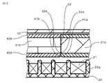
- FIG. 1 and 2 are a main part sectional view and an enlarged main part sectional view showing an ignition coil device for an internal combustion engine according to Embodiment 1 of the present invention.
- a primary coil 11 wound around a cylindrical primary bobbin 10 is provided in an insulating case 50.
- a cylindrical secondary bobbin 20 is provided outside the primary bobbin 10, and a secondary coil 21 is wound around the secondary bobbin 20.
- An I-type center iron core 30 passes through the center of the primary bobbin 10, and the primary coil 11 and the secondary coil 21 are disposed concentrically with respect to the center iron core 30.
- a side iron core 31 that forms a magnetic path together with the center iron core 30 forms a C-type side iron core divided into a plurality of parts, and is disposed so as to surround the primary coil 11 and the secondary coil 21.
- the side iron core 31 is covered with an elastomer material 40 such as a thermosetting or thermoplastic elastomer for the purpose of relieving thermal stress.
- An insulating resin 60 such as a thermosetting epoxy resin is injected into the insulating case 50 and then solidified.
- this ignition coil device is energized / interrupted in the primary coil 11 housed in the insulating case 50, for example, as in the ignition coil device disclosed in Japanese Patent Application Laid-Open No. 2010-27669.
- An igniter that performs the above operation, a low-pressure side connector that is provided integrally with the insulating case 50 and is electrically connected to the igniter, a high-pressure side connector that is electrically connected to the spark plug, and the like are provided.
- a drive signal from an external electronic control unit flows to the igniter via the low-voltage side connector, and controls energization and interruption of the primary current flowing to the primary coil 11.
- a secondary bobbin 20 around which a secondary coil 21 is wound has a plurality of flanges 20a (seven in the figure) made of an annular flat plate surrounding the outer periphery of a cylindrical base portion spaced apart from each other in the axial direction. A plurality of sections (six in the figure) are defined between adjacent flanges 20a.
- the secondary coil 21 is dividedly wound into sections sectioned by the flange 20a, and an insulation-coated copper wire having a predetermined wire diameter is wound a predetermined number of turns from one end side to the other end side in the axial direction. Is repeated.
- the secondary coil 21 has a low voltage side on the igniter side (right end side in FIG. 1) and a high voltage side on the other end side (left end side in FIG. 1).
- the side iron core 31 is divided into two side iron cores 31a and 31b by a dividing portion 33 formed in a direction parallel to the flange 20a of the secondary bobbin 20 at a portion facing the secondary coil 21.
- the side iron cores 31a and 31b are coated with elastomer materials 40a and 40b on substantially the entire outer periphery excluding the end face of the center iron core 30, respectively.
- Each of the side iron cores 31a, 31b and each of the elastomer materials 40a, 40b has a corner portion (hereinafter referred to as a secondary coil side corner portion) 32a facing the secondary coil 21 of the split end portion which is an end portion on the split portion 33 side.
- the positions of 32b, 41a, 41b are set near the middle of the third section of the secondary bobbin 20. Further, the corner portions 32a, 32b, 41a, 41b at the divided end portions of the side iron cores 31a, 31b and the elastomer materials 40a, 40b are formed to have an R shape (see FIG. 2).
- the ignition coil device for the internal combustion engine includes the side iron cores 31a and 31b divided into two parts and the divided end portions of the elastomer materials 40a and 40b covering the side iron cores 31a and 31b.
- the positions of the secondary coil side corner portions 32a, 32b, 41a, 41b are set near the middle of the third section of the secondary bobbin 20. For this reason, the secondary coil side corner portions 32a, 32b, 41a, 41b of the divided end portions of the side iron cores 31a, 31b and the elastomer materials 40a, 40b where the electric field and the thermal stress are concentrated are separated from the insulating resin 60.
- the insulation distance can be sufficiently secured away from the flange 20a of the secondary bobbin 20, which is inferior to that of the secondary bobbin 20, it is possible to ensure insulation while avoiding unnecessary enlargement.
- the corner portions 32a, 32b, 41a, 41b at the divided end portions of the side iron cores 31a, 31b and the elastomer materials 40a, 40b have an R shape, excessive electric field concentration and cold heat are generated at the corner portions. It is possible to prevent stress from being applied.
- the positions of the secondary coil side corner portions 32a, 32b of the side iron cores 31a, 31b and the secondary coil side corner portions 41a, 41b of the elastomer materials 40a, 40b are set to the positions of the secondary bobbin 20. Although it is in the vicinity of the middle of the section, if the positions of these corner portions 32a, 32b, 41a, 41b are set to be different from the arrangement position of the flange 20a of the secondary bobbin 20 in the axial direction of the secondary coil 21, It may be set between other sections.
- the positions of the secondary coil side corner portions 32a and 32b of the side iron cores 31a and 31b and the secondary coil side corner portions 41a and 41b of the elastomer materials 40a and 40b are set in the same section of the secondary bobbin 20. However, they may be set in different sections.
- the primary coil 11 wound around the cylindrical primary bobbin 10 and the plurality of flanges 20a are arranged in parallel at intervals in the axial direction.
- a cylindrical secondary bobbin 20 formed and a secondary coil 21 wound around a plurality of sections defined between the flanges 20a of the secondary bobbin 20 and concentrically disposed on the outer periphery of the primary coil 11.
- a center iron core 30 penetrating the primary bobbin 10 and arranged concentrically with the primary coil 11 and the secondary coil 21, and the primary coil 11 and the secondary coil so as to form a magnetic path together with the center iron core 30.
- Elastomer material that surrounds each of the side iron cores 31a and 31b that are divided into a plurality of divisions 33 and that surrounds each of the divided side iron cores 31a and 31b.
- the ignition coil device for an internal combustion engine that includes the iron cores 31a and 31b and the elastomer materials 40a and 40b and includes the insulating case 50 in which the insulating resin 60 is injected and hardened in the internal space, the side iron cores 31a and 31b and the elastomer materials
- the positions of the secondary coil side corner portions 32a, 32b, 41a, 41b of the split end portion, which is the end portion on the split portion 33 side, are the positions of the flange 20a of the secondary bobbin 20 in the axial direction of the secondary coil 21.
- the ignition coil device for an internal combustion engine configured in this way has a secondary iron side corner portion and a secondary coil side corner portion at the split end portion of the elastomer material where electric field and thermal stress are concentrated. Since a sufficient distance from the flange portion of the bobbin can be ensured, unnecessary insulation can be avoided and insulation can be ensured.
- FIG. FIG. 3 is a cross-sectional view of a main part showing the ignition coil device for an internal combustion engine according to the second embodiment of the present invention.
- 32b, 41a, 41b are set near the middle of the first section of the secondary bobbin 20.
- Other configurations are the same as those of the first embodiment.
- the electric field is concentrated on the secondary coil side corner portions 32a, 32b, 41a, 41b because the potential of the first section (low pressure side) of the secondary bobbin 20 is the lowest. Even in this case, the insulation resistance can be ensured without exceeding the withstand voltage of the insulating resin and without increasing the size.
- the secondary coil 21 can be secured from the flange 20a of the secondary bobbin 20 while ensuring the withstand voltage. It is also easy to secure the distance.
- FIG. FIG. 4 is a cross-sectional view of a main part showing an ignition coil device for an internal combustion engine according to Embodiment 3 of the present invention.
- the divided portion 33 of the side iron core 31 is an inclined side inclined with respect to the flange 20a of the secondary bobbin 20, and the secondary coil side corner portion 32a of each side iron core 31a, 31b. , 32b is set near the middle of the first section of the secondary bobbin 20.
- the position of the secondary coil side corner portion 41a in the divided end portion of the elastomer material 40a covering the side iron core 31a is located near the middle of the second section of the secondary bobbin 20, and the divided end portion of the elastomer material 40b covering the side iron core 31b.
- the position of the secondary coil side corner portion 41b is set near the middle of the third section of the secondary bobbin 20.
- the thickness of the elastomer material is set to about 0.5 mm to 1.5 mm, and each section width and flange thickness of the secondary bobbin 20 is set to 1.5 mm or more even on the narrowest high-pressure side.
- the thicknesses of the elastomer materials 40a and 40b are set to about 1.0 mm, and the secondary coil side corner portion 41a is set to the second section, and the secondary coil side corner portion 41b is set near the middle of the third section.
- the elastomer materials 40a and 40b have a distance between divisions of about 5.0 mm, and are configured to have a distance between divisions equal to or greater than the thickness of the elastomer materials 40a and 40b.
- Other configurations are the same as those of the first embodiment.
- the distance between the divided portions of the elastomer materials 40a and 40b covering the side iron cores 31a and 31b is at least equal to or greater than the thickness of the elastomer materials 40a and 40b.
- the insulating resin layer injected and cured between the elastomer materials can be prevented from becoming thin, the possibility of cracking in the insulating resin layer when applying a thermal stress is reduced, and the insulating property is reduced when applying a thermal stress. Can be prevented.
- the positions of the secondary coil side corner portions 31a, 31b, 41a, 41b of the divided end portions of the side iron cores 31a, 31b and the elastomer materials 40a, 40b are different from those of the secondary bobbin 20.
- the secondary bobbin with a narrow space between the sections the separation distance between the flange of the secondary bobbin, the divided ends of each side iron core, and the divided ends of each elastomer material is kept sufficiently even if a secondary bobbin with a narrow section is used. It is possible to suppress unnecessary enlargement and ensure durability.
- the gap length between the divided portions is the same level whether the cross section is vertical or inclined, whereas the cross sectional area of the magnetic circuit increases. An increase in magnetic resistance due to component variations can be suppressed.
- the divided portion 33 of the side iron core 31 is formed obliquely from the first section to the second section of the secondary bobbin 20, and the secondary coil side corner portion 41a of the divided end portion of the elastomer material 40a. Is set near the middle of the second section of the secondary bobbin 20, and the position of the secondary coil side corner 41b at the split end of the elastomer material 40b is set near the middle of the third section of the secondary bobbin 20. As long as the gap is formed between the divided end portions of the elastomer materials 40a and 40b, the position may be set at a position corresponding to another section.
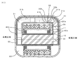
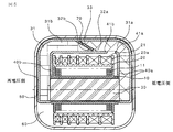
- FIG. 5 and 6 are a main part sectional view and an enlarged main part sectional view showing an ignition coil device for an internal combustion engine according to a fourth embodiment of the present invention.
- the divided portion 33 of the side iron core 31 is an oblique side inclined from the second section to the third section of the secondary bobbin 20 with respect to the flange 20 a of the secondary bobbin 20.
- a magnet 70 for improving the magnetic efficiency is inserted between the divided portions 33 of the side iron core 31, and the edge portion 70a on the opposite side of the secondary coil of the magnet 70 is located further inside than the opposite surface of the side iron core 31a ( The side away from the secondary coil 21) (see FIG. 6).
- the positions of the secondary coil side corner portions 32a, 32b of the divided end portions of the side iron cores 31a, 31b are set in the vicinity of the middle of the second section of the secondary bobbin 20. Further, the position of the secondary coil side corner portion 41b of the divided end portion of the elastomer material 40b covering the side iron core 31a is set to the first section of the secondary bobbin 20, and the secondary coil side corner portion 41a of the divided end portion of the elastomer material 40a. Is located outside the wall surface of the low-pressure side section end of the secondary bobbin 20, and a large inter-division distance is secured with respect to the split end portions of the elastomer materials 40a and 40b.
- the angle of the secondary coil side corner portion 32b at the divided end portion of the side iron core 31b is set to be an acute angle as compared with the angle of the secondary coil side corner portion 32a at the divided end portion on the side iron core 31a side. Further, the entire periphery of the corners of the side iron core 31b and the magnet 70 is covered with an elastomer material 40b, and the assembly of the magnet 70 is surrounded by the elastomer material 40b. Other configurations are the same as those of the first embodiment.
- the edge portion 70a of the magnet 70 inserted between the divided portions 33 of the side iron core 31 is on the inner side (the side away from the secondary coil 21) from the side iron core surface.
- the magnet 70 does not protrude from the side iron core surface, and an insulation distance can be secured even when an electric field is concentrated on the edge portion of the magnet 70.
- the divided portion 33 of the side iron core 31 is the hypotenuse and the magnet 70 is inserted between the divided portions 33 of the side iron core 31, the cross-sectional area of the magnetic circuit is increased, resulting in component variations.
- the secondary coil side corner portions 32a and 32b of the divided end portions of the side iron cores 31a and 31b have an angle on the side iron core 31b side close to the high voltage side flange of the secondary bobbin 20, Compared with the angle on the side iron core 31a side near the low-voltage side flange of the secondary bobbin 20, the secondary coil side corner portion 32b on the acute angle side is on the secondary coil side corner portion on the obtuse angle side. It is arranged so that the distance from the flange 20a of the secondary bobbin 20 is slightly longer than 32a.
- the side iron core 31b on the acute angle side to which a larger electric field or thermal stress is applied, and the secondary whose insulation resistance is inferior A distance between the flanges 20a of the bobbin 20 can be secured. Further, since the entire corners of the side iron core 31b and the magnet 70 are covered with the elastomer material 40b, the thermal stress on the entire circumference of the side iron core 31b and the corners of the magnet 70 can be alleviated. In addition, since the elastomer material 40b surrounds the assembly surface of the magnet 70, the elastomer material 40b serves as a positioning when the magnet 70 is assembled, and the assemblability is improved. Moving to the side can also be prevented.
- the divided portion 33 of the side iron core 31 is formed obliquely from the second section to the third section of the secondary bobbin 20, and the secondary coil side corner portion 41b of the divided end portion of the elastomer material 40b. Is positioned near the middle of the first section of the secondary bobbin 20, and the corner 41a facing the secondary coil at the split end of the elastomer 40a is positioned outside the wall of the low-pressure section end of the secondary bobbin 20.
- the magnet does not protrude from the side iron core surface to the secondary coil side, the problem of insulation deterioration due to electric field concentration on the magnet and peeling or cracking due to thermal stress even with a configuration not covered with an elastomer material is Disappear. Further, if the elastomer material covers the magnet, the magnet can function to prevent misalignment with respect to the magnet. Therefore, there is no problem even if the division position of the elastomer material is in another section of the secondary bobbin.
Landscapes
- Engineering & Computer Science (AREA)
- Power Engineering (AREA)
- Ignition Installations For Internal Combustion Engines (AREA)
Abstract
センタ鉄心(30)と共に磁気経路を形成するように1次コイル(11)及び2次コイル(21)を囲むと共に、2次コイルと対向する部分に形成された分割部(33)において複数に分割されたサイド鉄心 (31a,31b)と、複数に分割された各サイド鉄心の周囲をそれぞれ被覆するエラストマ材(40a,40b)と、センタ鉄心、1次コイル、2次コイル、サイド鉄心)、エラストマ材を収納し、内部空間に絶縁樹脂(60)が注入硬化された絶縁ケース(50)を備えた内燃機関用点火コイル装置において、各サイド鉄心(31a,31b)及び各エラストマ材(40a,40b)は、分割部側の端部である分割端部の2次コイル側コーナー部(32a,32b,41a,41b)の位置が2次コイルの軸方向において2次ボビン(20)のフランジ(20a)の配置位置と異なるように設定されている。
Description
本発明は主として車両用内燃機関、例えば自動車の内燃機関に取り付けられ、点火プラグに高電圧を供給し火花放電を発生させる点火コイル装置に関するものである。
近年の燃費改善のニーズよりエンジン(内燃機関)圧縮比を向上させ燃費向上を図る車両や、ダウンサイジングターボ化により燃費改善を図る車両が開発されている。
圧縮比増加により、点火コイル装置としては出力電圧を増加させる必要があり、これとともに、点火コイル装置内部の耐圧を向上させる必要がある。
またその他補機取付による燃費改善策も採用される場合もあり、点火コイル装置取付スペースに制限が加わることから点火コイル装置として小型・軽量化のニーズもある。
このため、点火コイル装置としては小型で高出力電圧、高耐圧であることが望まれている。
圧縮比増加により、点火コイル装置としては出力電圧を増加させる必要があり、これとともに、点火コイル装置内部の耐圧を向上させる必要がある。
またその他補機取付による燃費改善策も採用される場合もあり、点火コイル装置取付スペースに制限が加わることから点火コイル装置として小型・軽量化のニーズもある。
このため、点火コイル装置としては小型で高出力電圧、高耐圧であることが望まれている。
内燃機関用点火コイル装置は、例えば、センタ鉄心(中心コア)の外周に1次コイルと2次コイルを巻回し、その外側に、サイド鉄心(外周コア)を配置して構成される。
これら部品は、絶縁ケース内に収容され、ケース内の空間には絶縁樹脂等が充填されて絶縁を保っている。
また、冷熱応力緩和のために、サイド鉄心の周囲をエラストマ材で被覆している構造のものがあり、点火コイル装置の組付け性のためサイド鉄心を分割したり、磁気効率向上のため、サイド鉄心の分割位置にマグネットを挿入したりして用いるものがある。
サイド鉄心の分割端部及びエラストマ材の分割端部には電界集中や冷熱応力集中が発生し、電界集中による絶縁性の低下や、応力集中による剥離、クラックなどによる絶縁性の低下が生じる場合があり、サイド鉄心の周囲をエラストマ材で被覆する構造は、熱応力緩和には有効であるものの、エラストマ材自身の耐電圧特性は、絶縁樹脂等の絶縁充填材と比較して低い。
また2次コイルが巻装される2次ボビンと絶縁樹脂の境界面は、絶縁樹脂または2次ボビンより絶縁耐圧が劣る。
しかも、エラストマ材と絶縁充填材との間で剥離が生じた場合は、剥離部空気層の電界が高くなるため、電界集中部や絶縁耐力が弱い部分の絶縁距離を確保する必要がある。
また、大型化を防ぎ絶縁性を確保するために2次ボビンの壁面高さを低くするなどして絶縁性を高めた例がある(特許文献1参照)。
これら部品は、絶縁ケース内に収容され、ケース内の空間には絶縁樹脂等が充填されて絶縁を保っている。
また、冷熱応力緩和のために、サイド鉄心の周囲をエラストマ材で被覆している構造のものがあり、点火コイル装置の組付け性のためサイド鉄心を分割したり、磁気効率向上のため、サイド鉄心の分割位置にマグネットを挿入したりして用いるものがある。
サイド鉄心の分割端部及びエラストマ材の分割端部には電界集中や冷熱応力集中が発生し、電界集中による絶縁性の低下や、応力集中による剥離、クラックなどによる絶縁性の低下が生じる場合があり、サイド鉄心の周囲をエラストマ材で被覆する構造は、熱応力緩和には有効であるものの、エラストマ材自身の耐電圧特性は、絶縁樹脂等の絶縁充填材と比較して低い。
また2次コイルが巻装される2次ボビンと絶縁樹脂の境界面は、絶縁樹脂または2次ボビンより絶縁耐圧が劣る。
しかも、エラストマ材と絶縁充填材との間で剥離が生じた場合は、剥離部空気層の電界が高くなるため、電界集中部や絶縁耐力が弱い部分の絶縁距離を確保する必要がある。
また、大型化を防ぎ絶縁性を確保するために2次ボビンの壁面高さを低くするなどして絶縁性を高めた例がある(特許文献1参照)。
しかし、従来の内燃機関用点火コイル装置においては、単純に絶縁距離を確保した場合、大型化につながり、2次ボビンの高さを低くした場合、2次コイルの巻線部の壁がなくなる部分が出来るため、巻線の乱れが発生し、巻線内の絶縁性が低下する懸念があった。
本発明は、上記に鑑み提案されたもので、大型化を抑制し、2次コイル内の絶縁性を低下させることなく2次コイルとサイド鉄心との間の絶縁性を確保する内燃機関用点火コイル装置を得ることを目的としている。
本発明の内燃機関用点火コイル装置は、筒状の1次ボビンに巻装された1次コイルと、軸方向に間隔を置いて複数のフランジが並行に形成された筒状の2次ボビンと、前記2次ボビンのフランジ間に区画された複数のセクションに巻装され、前記1次コイルの外周に同心的に配置された2次コイルと、前記1次ボビンを貫通し、前記1次コイル及び2次コイルと同心的に配置されたセンタ鉄心と、前記センタ鉄心と共に磁気経路を形成するように前記1次コイル及び2次コイルを囲むと共に、前記2次コイルと対向する部分に形成された分割部において複数に分割されたサイド鉄心と、前記分割された各サイド鉄心の周囲をそれぞれ被覆するエラストマ材と、前記センタ鉄心、1次コイル、2次コイル、サイド鉄心、エラストマ材を収納し、内部空間に絶縁樹脂が注入硬化された絶縁ケースを備えた内燃機関用点火コイル装置において、前記サイド鉄心及びエラストマ材は、前記分割部側の端部である分割端部の2次コイル側コーナー部の位置が前記2次コイルの軸方向において前記2次ボビンのフランジの配置位置と異なるように設定されている。
本発明の内燃機関用点火コイル装置によれば、電界及び応力が集中するサイド鉄心及びエラストマ材の分割端部における2次コイル側コーナー部を、絶縁性が低下する2次ボビンのフランジ部から離して配置することができ、2次ボビンのフランジを小さくすることなく大型化を防ぎ耐圧を確保することができる。
実施の形態1.
以下、図面に基づいて本発明を詳細に説明する。
図1及び図2は、本発明の実施の形態1の内燃機関用点火コイル装置を示す要部断面図、及び要部拡大断面図である。
図1において、絶縁ケース50内に、筒状の1次ボビン10に巻装された1次コイル11が設けられている。
1次ボビン10の外側には、筒状の2次ボビン20が設けられ、2次ボビン20には2次コイル21が巻装されている。
I型のセンタ鉄心30が1次ボビン10の中心を貫通し、1次コイル11及び2次コイル21がセンタ鉄心30に対し同心的に配置されている。
センタ鉄心30と共に磁気経路を形成するサイド鉄心31は、複数に分割されたC型サイド鉄心を形成し、1次コイル11及び2次コイル21を囲むように配置されている。
サイド鉄心31は、冷熱応力緩和のために、外周を熱硬化性又は熱可塑性エラストマなどのエラストマ材40で覆われている。
絶縁ケース50内には、熱硬化性エポキシ樹脂などの絶縁樹脂60が注入され、その後固化されている。
以下、図面に基づいて本発明を詳細に説明する。
図1及び図2は、本発明の実施の形態1の内燃機関用点火コイル装置を示す要部断面図、及び要部拡大断面図である。
図1において、絶縁ケース50内に、筒状の1次ボビン10に巻装された1次コイル11が設けられている。
1次ボビン10の外側には、筒状の2次ボビン20が設けられ、2次ボビン20には2次コイル21が巻装されている。
I型のセンタ鉄心30が1次ボビン10の中心を貫通し、1次コイル11及び2次コイル21がセンタ鉄心30に対し同心的に配置されている。
センタ鉄心30と共に磁気経路を形成するサイド鉄心31は、複数に分割されたC型サイド鉄心を形成し、1次コイル11及び2次コイル21を囲むように配置されている。
サイド鉄心31は、冷熱応力緩和のために、外周を熱硬化性又は熱可塑性エラストマなどのエラストマ材40で覆われている。
絶縁ケース50内には、熱硬化性エポキシ樹脂などの絶縁樹脂60が注入され、その後固化されている。
なお、図示されていないが、この点火コイル装置には、例えば、特開2010-27669号公報の点火コイル装置と同様に、絶縁ケース50内に収納され1次コイル11への電流の通電・遮断を行うイグナイタや、絶縁ケース50と一体に設けられ、イグナイタと電気的に接続される低圧側コネクタと、点火プラグと電気的に接続される高圧側コネクタなどが設けられている。
外部の電子制御ユニットからの駆動信号が、低圧側コネクタを介してイグナイタに流れ、1次コイル11に流れる1次電流の通電、遮断を制御する。
この駆動信号により、内燃機関の所定の点火時期に1次コイル11に流れる1次電流を遮断すると、1次コイル11に逆起電力が発生し、2次コイル21に高電圧を発生する。
発生した高電圧は、高圧側コネクタを介して点火プラグに印加される。
外部の電子制御ユニットからの駆動信号が、低圧側コネクタを介してイグナイタに流れ、1次コイル11に流れる1次電流の通電、遮断を制御する。
この駆動信号により、内燃機関の所定の点火時期に1次コイル11に流れる1次電流を遮断すると、1次コイル11に逆起電力が発生し、2次コイル21に高電圧を発生する。
発生した高電圧は、高圧側コネクタを介して点火プラグに印加される。
図1において、2次コイル21が巻装されている2次ボビン20は、筒状基部の外周を取り巻く環状の平板からなる複数のフランジ20a(図では7個)が軸方向に所定間隔をおいて並設され、隣り合うフランジ20a間に複数のセクション(図では6個)を区画形成している。
2次コイル21は、フランジ20aによって区画された各セクションに分割巻線され、軸方向の一端側から他端側のセクションへ、所定線径の絶縁被覆銅線を所定のターン数巻回することを繰返して構成される。
通常は、2次コイル21は、イグナイタ側(図1の右端側)が低電圧側となり、他端側である(図1の左端側)が高電圧側となる。
2次コイル21は、フランジ20aによって区画された各セクションに分割巻線され、軸方向の一端側から他端側のセクションへ、所定線径の絶縁被覆銅線を所定のターン数巻回することを繰返して構成される。
通常は、2次コイル21は、イグナイタ側(図1の右端側)が低電圧側となり、他端側である(図1の左端側)が高電圧側となる。
本実施形態1では、サイド鉄心31は、2次コイル21と対向する部分に2次ボビン20のフランジ20aと平行な方向に形成された分割部33により2個のサイド鉄心31a,31bに分割され、各サイド鉄心31a,31bは、センタ鉄心30の端面を除いたほぼ全外周をそれぞれエラストマ材40a,40bにて被覆されている。
各サイド鉄心31a,31b及び各エラストマ材40a,40bは、分割部33側の端部である分割端部の2次コイル21に対向するコーナー部(以下、2次コイル側コーナー部という)32a,32b,41a,41bの位置が2次ボビン20の第3セクション中間付近に設定されている。
また、各サイド鉄心31a,31b及び各エラストマ材40a,40bの分割端部におけるコーナー部32a,32b,41a,41bは、R形状を有するように形成されている(図2参照)。
各サイド鉄心31a,31b及び各エラストマ材40a,40bは、分割部33側の端部である分割端部の2次コイル21に対向するコーナー部(以下、2次コイル側コーナー部という)32a,32b,41a,41bの位置が2次ボビン20の第3セクション中間付近に設定されている。
また、各サイド鉄心31a,31b及び各エラストマ材40a,40bの分割端部におけるコーナー部32a,32b,41a,41bは、R形状を有するように形成されている(図2参照)。
上記のように本実施形態1の内燃機関用点火コイル装置は、2つに分割されたサイド鉄心31a,31bと、これらのサイド鉄心31a,31bを被覆するエラストマ材40a,40bの分割端部の2次コイル側コーナー部32a,32b,41a,41bの位置が2次ボビン20の第3セクション中間付近に設定されている。
このため、電界及び冷熱応力が集中する各サイド鉄心31a,31b及び各エラストマ材40a,40bの分割端部の2次コイル側コーナー部32a,32b,41a,41bを、絶縁性が絶縁樹脂60と比較して劣る2次ボビン20のフランジ20aから離して絶縁距離を十分に確保できるため、不要な大型化を避け絶縁性を確保することができる。
また、各サイド鉄心31a,31b及び各エラストマ材40a,40bの分割端部におけるコーナー部32a,32b,41a,41bがR形状を有しているため、それらのコーナー部に過度な電界集中や冷熱応力が加わることを防ぐことができる。
このため、電界及び冷熱応力が集中する各サイド鉄心31a,31b及び各エラストマ材40a,40bの分割端部の2次コイル側コーナー部32a,32b,41a,41bを、絶縁性が絶縁樹脂60と比較して劣る2次ボビン20のフランジ20aから離して絶縁距離を十分に確保できるため、不要な大型化を避け絶縁性を確保することができる。
また、各サイド鉄心31a,31b及び各エラストマ材40a,40bの分割端部におけるコーナー部32a,32b,41a,41bがR形状を有しているため、それらのコーナー部に過度な電界集中や冷熱応力が加わることを防ぐことができる。
なお、本実施形態1では各サイド鉄心31a,31bの2次コイル側コーナー部32a,32b及び各エラストマ材40a,40bの2次コイル側コーナー部41a,41bの位置を2次ボビン20の第3セクション中間付近としているが、これらのコーナー部32a,32b,41a,41bの位置は、2次コイル21の軸方向において2次ボビン20のフランジ20aの配置位置と異なるように設定されておれば、他のセクション間に設定されていてもよい。
また、各サイド鉄心31a,31bの2次コイル側コーナー部32a,32b及び各エラストマ材40a,40bの2次コイル側コーナー部41a,41bの位置を2次ボビン20の同一セクション内に設定しているが、互いに異なるセクション内に設定してもよい。
また、各サイド鉄心31a,31bの2次コイル側コーナー部32a,32b及び各エラストマ材40a,40bの2次コイル側コーナー部41a,41bの位置を2次ボビン20の同一セクション内に設定しているが、互いに異なるセクション内に設定してもよい。
以上のように、本実施形態1の内燃機関用点火コイル装置は、筒状の1次ボビン10に巻装された1次コイル11と、軸方向に間隔を置いて複数のフランジ20aが並行に形成された筒状の2次ボビン20と、2次ボビン20のフランジ20a間に区画された複数のセクションに巻装され、前記1次コイル11の外周に同心的に配置された2次コイル21と、1次ボビン10を貫通し、1次コイル11及び2次コイル21と同心的に配置されたセンタ鉄心30と、センタ鉄心30と共に磁気経路を形成するように1次コイル11及び2次コイル21を囲むと共に、2次コイル21と対向する部分に形成された分割部33において複数に分割されたサイド鉄心31a,31bと、分割された各サイド鉄心31a,31bの周囲をそれぞれ被覆するエラストマ材40a,40bと、センタ鉄心30、1次コイル11、2次コイル21、サイド鉄心31a,31b、及びエラストマ材40a,40bを収納し、内部空間に絶縁樹脂60が注入硬化された絶縁ケース50を備えた内燃機関用点火コイル装置において、各サイド鉄心31a,31b及び各エラストマ材40a,40bは、分割部33側の端部である分割端部の2次コイル側コーナー部32a,32b,41a,41bの位置が2次コイル21の軸方向において2次ボビン20のフランジ20aの配置位置と異なるように設定されている。
このように構成した内燃機関用点火コイル装置は、電界及び冷熱応力が集中するサイド鉄心及びエラストマ材の分割端部における2次コイル側コーナー部を、絶縁性が絶縁樹脂と比較して劣る2次ボビンのフランジ部からの距離を十分に確保できるため、不要な大型化を避け絶縁性を確保することができる。
このように構成した内燃機関用点火コイル装置は、電界及び冷熱応力が集中するサイド鉄心及びエラストマ材の分割端部における2次コイル側コーナー部を、絶縁性が絶縁樹脂と比較して劣る2次ボビンのフランジ部からの距離を十分に確保できるため、不要な大型化を避け絶縁性を確保することができる。
実施の形態2.
図3は、本発明の実施の形態2の内燃機関用点火コイル装置を示す要部断面図である。
本実施形態2では、図3に示すように各サイド鉄心31a,31bの分割端部及び各サイド鉄心31a,31bを被覆する各エラストマ材40a,40bの分割端部における2次コイル側コーナー部32a,32b,41a,41bの位置を2次ボビン20の第1セクション中間付近に設定している。その他の構成は実施形態1と同様である。
図3は、本発明の実施の形態2の内燃機関用点火コイル装置を示す要部断面図である。
本実施形態2では、図3に示すように各サイド鉄心31a,31bの分割端部及び各サイド鉄心31a,31bを被覆する各エラストマ材40a,40bの分割端部における2次コイル側コーナー部32a,32b,41a,41bの位置を2次ボビン20の第1セクション中間付近に設定している。その他の構成は実施形態1と同様である。
以上のように構成した内燃機関用点火コイル装置は、2次ボビン20の第1セクション(低圧側)の電位が最も低いため2次コイル側コーナー部32a,32b,41a,41bに電界が集中した場合にも絶縁樹脂の耐圧を超えることがなく、大型化することなく絶縁性を確保することができる。
また、通常2次コイル21の電位分布の平準化を考慮した場合、2次ボビン20の第1セクション幅が最も広いため、2次コイル21の耐圧を確保しつつ2次ボビン20のフランジ20aからの距離を確保することも容易になる。
また、通常2次コイル21の電位分布の平準化を考慮した場合、2次ボビン20の第1セクション幅が最も広いため、2次コイル21の耐圧を確保しつつ2次ボビン20のフランジ20aからの距離を確保することも容易になる。
実施の形態3.
図4は、本発明の実施の形態3の内燃機関用点火コイル装置を示す要部断面図である。
本実施形態3では図4に示すように、サイド鉄心31の分割部33を2次ボビン20のフランジ20aに対し傾斜する斜辺とするとともに、各サイド鉄心31a,31bの2次コイル側コーナー部32a,32bの位置を2次ボビン20の第1セクション中間付近に設定している。
また、サイド鉄心31aを被覆するエラストマ材40aの分割端部における2次コイル側コーナー部41aの位置を2次ボビン20の第2セクション中間付近、サイド鉄心31bを被覆するエラストマ材40bの分割端部における2次コイル側コーナー部41bの位置を2次ボビン20の第3セクション中間付近に設定している。
図4は、本発明の実施の形態3の内燃機関用点火コイル装置を示す要部断面図である。
本実施形態3では図4に示すように、サイド鉄心31の分割部33を2次ボビン20のフランジ20aに対し傾斜する斜辺とするとともに、各サイド鉄心31a,31bの2次コイル側コーナー部32a,32bの位置を2次ボビン20の第1セクション中間付近に設定している。
また、サイド鉄心31aを被覆するエラストマ材40aの分割端部における2次コイル側コーナー部41aの位置を2次ボビン20の第2セクション中間付近、サイド鉄心31bを被覆するエラストマ材40bの分割端部における2次コイル側コーナー部41bの位置を2次ボビン20の第3セクション中間付近に設定している。
一般的にエラストマ材の厚みは0.5mm~1.5mm程度に設定され、2次ボビン20の各セクション幅+フランジ厚みは最も狭い高圧側においても1.5mm以上と設定されるため、エラストマ材40a,40bの分割端部における2次コイル側コーナー部41a,41bを2次ボビン20の異なるセクション間に設けることで、エラストマ材の厚みに対し、エラストマ材40a,40bの分割端部間の距離(以下、分割間距離という)を大きくすることが可能である。
本実施形態では、エラストマ材40a,40bの厚みを1.0mm程度に設定すると共に、2次コイル側コーナー部41aを第2セクション、2次コイル側コーナー部41bを第3セクション中間付近に設定することで、エラストマ材40a,40bは5.0mm程度の分割間距離を有し、エラストマ材40a,40bの厚み以上の分割間距離を有するように構成している。その他の構成は実施形態1と同様である。
本実施形態では、エラストマ材40a,40bの厚みを1.0mm程度に設定すると共に、2次コイル側コーナー部41aを第2セクション、2次コイル側コーナー部41bを第3セクション中間付近に設定することで、エラストマ材40a,40bは5.0mm程度の分割間距離を有し、エラストマ材40a,40bの厚み以上の分割間距離を有するように構成している。その他の構成は実施形態1と同様である。
分割された各々のサイド鉄心31a,31bをエラストマ材40a,40bで被覆する場合、サイド鉄心31a,31bやエラストマ材40a.40bの寸法ばらつきや成形後の収縮などによりエラストマ材間の距離ばらつきが発生するが、これらが発生した場合にも、サイド鉄心31a,31bの分割端部間にギャップが生じない(エラストマ材同士がサイド鉄心より先に接触しない)ようにする必要があり、また、ばらつきによってはエラストマ材間にギャップが発生する事になるため、エラストマ材間に狭小な絶縁樹脂層が形成されることとなる。
しかし、エラストマ材と絶縁樹脂の線膨張係数は異なるため、冷熱応力が絶縁樹脂層に印加されることになり、この部分の強度が十分でない場合、クラックが発生する懸念がある。
しかし、エラストマ材と絶縁樹脂の線膨張係数は異なるため、冷熱応力が絶縁樹脂層に印加されることになり、この部分の強度が十分でない場合、クラックが発生する懸念がある。
よって本実施形態3のように、各サイド鉄心31a,31bを覆う各エラストマ材40a,40bの分割端部間に、少なくともエラストマ材40a,40bの厚み以上の分割間距離をあけるように構成すれば、エラストマ材間に注入、硬化される絶縁樹脂層が薄くなる事を防止できるため、冷熱応力印加時に絶縁樹脂層にクラックが発生する可能性が低くなり、冷熱応力印加時に絶縁性が低下することを防止できる。
また、本実施形態3のように各サイド鉄心31a,31b及び各のエラストマ材40a,40bの分割端部の2次コイル側コーナー部31a,31b,41a,41bの位置を2次ボビン20の異なるセクションに位置させることにより、セクション間が狭い2次ボビンを用いる場合にも2次ボビンのフランジと、各サイド鉄心の分割端部間及び各エラストマ材の分割端部間の分割距離を十分保つことができ不要な大型化を抑制し耐久性を確保することができる。
また、本実施形態3では、サイド鉄心31の分割部33を斜辺としているため、分割部間のギャップ長は断面が垂直でも斜面でも同じレベルであるのに対し、磁気回路の断面積が増加し部品バラツキによる磁気抵抗の増加を抑制することができる。
また、本実施形態3のように各サイド鉄心31a,31b及び各のエラストマ材40a,40bの分割端部の2次コイル側コーナー部31a,31b,41a,41bの位置を2次ボビン20の異なるセクションに位置させることにより、セクション間が狭い2次ボビンを用いる場合にも2次ボビンのフランジと、各サイド鉄心の分割端部間及び各エラストマ材の分割端部間の分割距離を十分保つことができ不要な大型化を抑制し耐久性を確保することができる。
また、本実施形態3では、サイド鉄心31の分割部33を斜辺としているため、分割部間のギャップ長は断面が垂直でも斜面でも同じレベルであるのに対し、磁気回路の断面積が増加し部品バラツキによる磁気抵抗の増加を抑制することができる。
なお、本実施形態3ではサイド鉄心31の分割部33を2次ボビン20の第1セクションから第2セクションに渡って斜めに形成し、エラストマ材40aの分割端部の2次コイル側コーナー部41aの位置を2次ボビン20の第2セクション中間付近、エラストマ材40bの分割端部の2次コイル側コーナー部41bの位置を2次ボビン20の第3セクション中間付近に設定しているが、各エラストマ材40a,40bの分割端部間に隙間ができるような構成であれば、別のセクションに対応する位置に設定してもよい。
実施の形態4.
図5及び図6は、本発明の実施の形態4の内燃機関用点火コイル装置を示す要部断面図、及び要部拡大断面図である。
本実施形態4では、図5に示すようにサイド鉄心31の分割部33を、2次ボビン20のフランジ20aに対し2次ボビン20の第2セクションから第3セクションに渡って傾斜する斜辺とするとともに、サイド鉄心31の分割部33間に磁気効率向上のためのマグネット70を挿入し、マグネット70の2次コイル対向側のエッジ部70aをサイド鉄心31aの2次コイル対向面に対しより内側(2次コイル21から離れる側)となるよう構成した(図6参照)。
また、各サイド鉄心31a,31bの分割端部の2次コイル側コーナー部32a,32bの位置を2次ボビン20の第2セクション中間付近に設定している。
更に、サイド鉄心31aを被覆するエラストマ材40bの分割端部の2次コイル側コーナー部41bの位置を2次ボビン20の第1セクション、エラストマ材40aの分割端部の2次コイル側コーナー部41aの位置を2次ボビン20の低圧側セクション端の壁面外とし、エラストマ材40a、40bの分割端部に対して、分割間距離を大きく確保している。
更に、サイド鉄心31bの分割端部の2次コイル側コーナー部32b の角度がサイド鉄心31a側の分割端部の2次コイル側コーナー部32aの角度と比較して鋭角になるようにしている。
更に、サイド鉄心31b及びマグネット70のコーナー全周をエラストマ材40bで覆うとともに、エラストマ材40bでマグネット70の組み付け面周囲を囲む構成をとっている。その他の構成は実施形態1と同様である。
図5及び図6は、本発明の実施の形態4の内燃機関用点火コイル装置を示す要部断面図、及び要部拡大断面図である。
本実施形態4では、図5に示すようにサイド鉄心31の分割部33を、2次ボビン20のフランジ20aに対し2次ボビン20の第2セクションから第3セクションに渡って傾斜する斜辺とするとともに、サイド鉄心31の分割部33間に磁気効率向上のためのマグネット70を挿入し、マグネット70の2次コイル対向側のエッジ部70aをサイド鉄心31aの2次コイル対向面に対しより内側(2次コイル21から離れる側)となるよう構成した(図6参照)。
また、各サイド鉄心31a,31bの分割端部の2次コイル側コーナー部32a,32bの位置を2次ボビン20の第2セクション中間付近に設定している。
更に、サイド鉄心31aを被覆するエラストマ材40bの分割端部の2次コイル側コーナー部41bの位置を2次ボビン20の第1セクション、エラストマ材40aの分割端部の2次コイル側コーナー部41aの位置を2次ボビン20の低圧側セクション端の壁面外とし、エラストマ材40a、40bの分割端部に対して、分割間距離を大きく確保している。
更に、サイド鉄心31bの分割端部の2次コイル側コーナー部32b の角度がサイド鉄心31a側の分割端部の2次コイル側コーナー部32aの角度と比較して鋭角になるようにしている。
更に、サイド鉄心31b及びマグネット70のコーナー全周をエラストマ材40bで覆うとともに、エラストマ材40bでマグネット70の組み付け面周囲を囲む構成をとっている。その他の構成は実施形態1と同様である。
以上のように構成した内燃機関用点火コイル装置は、サイド鉄心31の分割部33間に挿入されたマグネット70のエッジ部70aがサイド鉄心面より内側(2次コイル21から離れる側)にあるため、マグネット70の組み付け時にサイド鉄心面からマグネット70が突出することが無く、マグネット70のエッジ部に電界が集中した時にも絶縁距離を確保することができる。
また、本実施形態4では、サイド鉄心31の分割部33を斜辺とすると共に、サイド鉄心31の分割部33間にマグネット70を挿入しているため、磁気回路の断面積が増加し部品バラツキによる磁気抵抗の増加を抑制することができる上、分割部間に面積の大きいマグネットを挿入しやすい利点がある。
また、本実施形態4では、各サイド鉄心31a,31bの分割端部の2次コイル側コーナー部32a,32bは、2次ボビン20の高電圧側のフランジに近いサイド鉄心31b側の角度が、2次ボビン20の低電圧側のフランジに近いサイド鉄心31a側の角度と比較して鋭角になるようにし、鋭角側の2次コイル側コーナー部32bの方が鈍角側の2次コイル側コーナー部32aよりも2次ボビン20のフランジ20aとの距離が若干遠くなるように配置されており、このためより大きな電界や冷熱応力が印加される鋭角側のサイド鉄心31bと、絶縁耐量が劣る2次ボビン20のフランジ20a間の距離を確保することができる。
更に、サイド鉄心31b及びマグネット70のコーナー全周をエラストマ材40bで覆う構成をとっているため、サイド鉄心31b及びマグネット70のコーナー部全周の冷熱応力を緩和できる。
また、エラストマ材40bでマグネット70の組み付け面周囲を囲む構成をとっているため、エラストマ材40bがマグネット70の組み付け時の位置決めとして働き組付け性が向上し、組み付け時にマグネット70が2次コイル21側へ移動することも防止することができる。
また、本実施形態4では、サイド鉄心31の分割部33を斜辺とすると共に、サイド鉄心31の分割部33間にマグネット70を挿入しているため、磁気回路の断面積が増加し部品バラツキによる磁気抵抗の増加を抑制することができる上、分割部間に面積の大きいマグネットを挿入しやすい利点がある。
また、本実施形態4では、各サイド鉄心31a,31bの分割端部の2次コイル側コーナー部32a,32bは、2次ボビン20の高電圧側のフランジに近いサイド鉄心31b側の角度が、2次ボビン20の低電圧側のフランジに近いサイド鉄心31a側の角度と比較して鋭角になるようにし、鋭角側の2次コイル側コーナー部32bの方が鈍角側の2次コイル側コーナー部32aよりも2次ボビン20のフランジ20aとの距離が若干遠くなるように配置されており、このためより大きな電界や冷熱応力が印加される鋭角側のサイド鉄心31bと、絶縁耐量が劣る2次ボビン20のフランジ20a間の距離を確保することができる。
更に、サイド鉄心31b及びマグネット70のコーナー全周をエラストマ材40bで覆う構成をとっているため、サイド鉄心31b及びマグネット70のコーナー部全周の冷熱応力を緩和できる。
また、エラストマ材40bでマグネット70の組み付け面周囲を囲む構成をとっているため、エラストマ材40bがマグネット70の組み付け時の位置決めとして働き組付け性が向上し、組み付け時にマグネット70が2次コイル21側へ移動することも防止することができる。
なお、本実施形態4ではサイド鉄心31の分割部33を2次ボビン20の第2セクションから第3セクションに渡って斜めに形成し、エラストマ材40bの分割端部の2次コイル側コーナー部41bの位置を2次ボビン20の第1セクション中間付近、エラストマ材40aの分割端部の2次コイルに対向するコーナー部41aの位置を2次ボビン20の低圧セクション端の壁面外に設定しているが、マグネットがサイド鉄心面から2次コイル側に飛び出さない形態であれば、エラストマ材で覆っていない構成でもマグネットへの電界集中及び冷熱応力時の剥離やクラックなどによる絶縁性低下の問題は無くなる。
またエラストマ材がマグネットを覆う構成であれば、マグネットに対し位置ズレ防止の機能を果たすことができるため、エラストマ材の分割位置は2次ボビンの別セクションにあっても問題ない。
またエラストマ材がマグネットを覆う構成であれば、マグネットに対し位置ズレ防止の機能を果たすことができるため、エラストマ材の分割位置は2次ボビンの別セクションにあっても問題ない。
以上、本発明の実施の形態を記述したが、本発明は実施の形態に限定されるものではなく、種々の設計変更を行うことが可能であり、その発明の範囲内において、各実施の形態を自由に組み合わせたり、各実施の形態を適宜、変形、省略したりすることが可能である。
10 1次ボビン、11 1次コイル、20 2次ボビン、20a フランジ、21 2次コイル、30 センタ鉄心、31,31a,31b サイド鉄心、32a,32b 2次コイル側コーナー部、33 分割部、40,40a,40b エラストマ材、41a,41b 2次コイル側コーナー部、50 絶縁ケース、60 絶縁樹脂、70 マグネット、70a マグネットのエッジ部。
Claims (7)
- 筒状の1次ボビンに巻装された1次コイルと、
軸方向に間隔を置いて複数のフランジが並行に形成された筒状の2次ボビンと、
前記2次ボビンのフランジ間に区画された複数のセクションに巻装され、前記1次コイルの外周に同心的に配置された2次コイルと、
前記1次ボビンを貫通し、前記1次コイル及び2次コイルと同心的に配置されたセンタ鉄心と、
前記センタ鉄心と共に磁気経路を形成するように前記1次コイル及び2次コイルを囲むと共に、前記2次コイルと対向する部分に形成された分割部において複数に分割されたサイド鉄心と、
前記分割された各サイド鉄心の周囲をそれぞれ被覆するエラストマ材と、
前記センタ鉄心、1次コイル、2次コイル、サイド鉄心、及びエラストマ材を収納し、内部空間に絶縁樹脂が注入硬化された絶縁ケースを備えた内燃機関用点火コイル装置において、
前記サイド鉄心及びエラストマ材は、前記分割部側の端部である分割端部の2次コイル側コーナー部の位置が前記2次コイルの軸方向において前記2次ボビンのフランジの配置位置と異なるように設定されている
ことを特徴とする内燃機関用点火コイル装置。 - 前記各サイド鉄心及び各エラストマ材の分割端部は、前記2次コイル側コーナー部の位置が前記2次ボビンの低電圧側セクションに対応するように設定されていることを特徴とする請求項1に記載の内燃機関用点火コイル装置。
- 前記各サイド鉄心を覆う前記エラストマ材の分割端部は、前記エラストマ材の厚み以上の分割間距離を有することを特徴とする請求項1または2に記載の内燃機関用点火コイル装置。
- 前記サイド鉄心の分割端部間に挿入されたマグネットを有し、前記マグネットの2次コイル対向側のエッジ部を前記サイド鉄心の2次コイル対向面に対し前記2次コイルより離れる位置になるように配置したことを特徴とする請求項1から3のいずれか一項に記載の内燃機関用点火コイル装置。
- 前記各サイド鉄心及び前記各エラストマ材の分割端部の前記2次コイル側コーナー部はR形状を有することを特徴とする請求項1から4のいずれか一項に記載の内燃機関用点火コイル装置。
- 前記サイド鉄心の分割部を前記2次ボビンのフランジに対し傾斜する斜辺としたことを特徴とする請求項1から5のいずれか一項に記載の内燃機関用点火コイル装置。
- 前記サイド鉄心の分割端部の前記2次コイル側コーナー部は、鋭角側の2次コイル側コーナー部が鈍角側の2次コイル側コーナー部よりも前記2次ボビンのフランジとの距離が遠くなるように配置されていることを特徴とする請求項6に記載の内燃機関用点火コイル装置。
Priority Applications (5)
| Application Number | Priority Date | Filing Date | Title |
|---|---|---|---|
| PCT/JP2016/055804 WO2017145355A1 (ja) | 2016-02-26 | 2016-02-26 | 内燃機関用点火コイル装置 |
| CN201680081598.9A CN108701537B (zh) | 2016-02-26 | 2016-02-26 | 内燃机用点火线圈装置 |
| DE112016006501.9T DE112016006501T5 (de) | 2016-02-26 | 2016-02-26 | Zündspulenvorrichtung für Verbrennungsmotor |
| US15/771,587 US10438740B2 (en) | 2016-02-26 | 2016-02-26 | Ignition coil device for internal combustion engine |
| JP2018501524A JP6509424B2 (ja) | 2016-02-26 | 2016-02-26 | 内燃機関用点火コイル装置 |
Applications Claiming Priority (1)
| Application Number | Priority Date | Filing Date | Title |
|---|---|---|---|
| PCT/JP2016/055804 WO2017145355A1 (ja) | 2016-02-26 | 2016-02-26 | 内燃機関用点火コイル装置 |
Publications (1)
| Publication Number | Publication Date |
|---|---|
| WO2017145355A1 true WO2017145355A1 (ja) | 2017-08-31 |
Family
ID=59684905
Family Applications (1)
| Application Number | Title | Priority Date | Filing Date |
|---|---|---|---|
| PCT/JP2016/055804 Ceased WO2017145355A1 (ja) | 2016-02-26 | 2016-02-26 | 内燃機関用点火コイル装置 |
Country Status (5)
| Country | Link |
|---|---|
| US (1) | US10438740B2 (ja) |
| JP (1) | JP6509424B2 (ja) |
| CN (1) | CN108701537B (ja) |
| DE (1) | DE112016006501T5 (ja) |
| WO (1) | WO2017145355A1 (ja) |
Cited By (1)
| Publication number | Priority date | Publication date | Assignee | Title |
|---|---|---|---|---|
| US12576147B2 (en) | 2019-03-27 | 2026-03-17 | Inserm (Institut National De La Sante Et De La Recherche Medicale) | Recombinant proteins with CD40 activating properties |
Families Citing this family (2)
| Publication number | Priority date | Publication date | Assignee | Title |
|---|---|---|---|---|
| JP6648935B2 (ja) * | 2017-03-30 | 2020-02-14 | 三菱電機株式会社 | 点火コイル |
| JP7358839B2 (ja) * | 2019-08-22 | 2023-10-11 | 株式会社デンソー | 点火コイル |
Citations (5)
| Publication number | Priority date | Publication date | Assignee | Title |
|---|---|---|---|---|
| JPS60201607A (ja) * | 1984-03-26 | 1985-10-12 | Nippon Denso Co Ltd | 点火コイル |
| JPH10294228A (ja) * | 1997-04-18 | 1998-11-04 | Hanshin Electric Co Ltd | 内燃機関用点火コイル |
| JP2005019868A (ja) * | 2003-06-27 | 2005-01-20 | Hanshin Electric Co Ltd | 内燃機関用点火コイル |
| JP2006294914A (ja) * | 2005-04-12 | 2006-10-26 | Mitsubishi Electric Corp | 内燃機関用点火装置 |
| JP2012248645A (ja) * | 2011-05-27 | 2012-12-13 | Hitachi Automotive Systems Ltd | 内燃機関用点火コイル |
Family Cites Families (11)
| Publication number | Priority date | Publication date | Assignee | Title |
|---|---|---|---|---|
| ES2057622T3 (es) * | 1990-03-08 | 1994-10-16 | Nippon Denso Co | Bobina de encendido para un motor de combustion interna. |
| JP3229515B2 (ja) * | 1995-05-08 | 2001-11-19 | 三菱電機株式会社 | 内燃機関用点火装置 |
| JP3602267B2 (ja) * | 1996-07-12 | 2004-12-15 | 本田技研工業株式会社 | 点火コイル装置 |
| JP3727764B2 (ja) * | 1997-09-30 | 2005-12-14 | 株式会社日立製作所 | エンジン用点火コイル装置及びその製造方法 |
| JP3989073B2 (ja) * | 1998-01-07 | 2007-10-10 | 阪神エレクトリック株式会社 | 内燃機関の点火コイル |
| JP4658168B2 (ja) | 2008-07-15 | 2011-03-23 | 三菱電機株式会社 | 内燃機関用点火コイル装置、及びその製造方法 |
| CN201402734Y (zh) * | 2009-04-03 | 2010-02-10 | 楼甜甜 | 内部安装磁钢的点火线圈 |
| JP5846741B2 (ja) * | 2011-02-21 | 2016-01-20 | ダイヤモンド電機株式会社 | 内燃機関用の点火コイル |
| JP2013115075A (ja) * | 2011-11-25 | 2013-06-10 | Diamond Electric Mfg Co Ltd | 内燃機関用の点火コイル |
| JP6322978B2 (ja) | 2013-12-03 | 2018-05-16 | 株式会社デンソー | 内燃機関用点火コイル |
| CN204067016U (zh) * | 2014-09-30 | 2014-12-31 | 宁波市柏诺斯电器有限公司 | 一种汽车点火线圈 |
-
2016
- 2016-02-26 JP JP2018501524A patent/JP6509424B2/ja active Active
- 2016-02-26 CN CN201680081598.9A patent/CN108701537B/zh active Active
- 2016-02-26 DE DE112016006501.9T patent/DE112016006501T5/de not_active Ceased
- 2016-02-26 WO PCT/JP2016/055804 patent/WO2017145355A1/ja not_active Ceased
- 2016-02-26 US US15/771,587 patent/US10438740B2/en active Active
Patent Citations (5)
| Publication number | Priority date | Publication date | Assignee | Title |
|---|---|---|---|---|
| JPS60201607A (ja) * | 1984-03-26 | 1985-10-12 | Nippon Denso Co Ltd | 点火コイル |
| JPH10294228A (ja) * | 1997-04-18 | 1998-11-04 | Hanshin Electric Co Ltd | 内燃機関用点火コイル |
| JP2005019868A (ja) * | 2003-06-27 | 2005-01-20 | Hanshin Electric Co Ltd | 内燃機関用点火コイル |
| JP2006294914A (ja) * | 2005-04-12 | 2006-10-26 | Mitsubishi Electric Corp | 内燃機関用点火装置 |
| JP2012248645A (ja) * | 2011-05-27 | 2012-12-13 | Hitachi Automotive Systems Ltd | 内燃機関用点火コイル |
Cited By (1)
| Publication number | Priority date | Publication date | Assignee | Title |
|---|---|---|---|---|
| US12576147B2 (en) | 2019-03-27 | 2026-03-17 | Inserm (Institut National De La Sante Et De La Recherche Medicale) | Recombinant proteins with CD40 activating properties |
Also Published As
| Publication number | Publication date |
|---|---|
| JPWO2017145355A1 (ja) | 2018-05-31 |
| US20180350516A1 (en) | 2018-12-06 |
| US10438740B2 (en) | 2019-10-08 |
| CN108701537B (zh) | 2020-12-08 |
| CN108701537A (zh) | 2018-10-23 |
| JP6509424B2 (ja) | 2019-05-08 |
| DE112016006501T5 (de) | 2018-11-29 |
Similar Documents
| Publication | Publication Date | Title |
|---|---|---|
| JP2013026560A (ja) | 内燃機関用の点火コイル | |
| US20040231652A1 (en) | Ignition coil for an internal combustion engine | |
| JP6509424B2 (ja) | 内燃機関用点火コイル装置 | |
| JP4658168B2 (ja) | 内燃機関用点火コイル装置、及びその製造方法 | |
| US11482367B2 (en) | Ignition coil | |
| JP7101804B2 (ja) | 点火コイル | |
| JP4554696B2 (ja) | 内燃機関用点火装置 | |
| US7004155B2 (en) | Ignition apparatus for internal combustion engine | |
| JP6750811B1 (ja) | 内燃機関用点火装置 | |
| JP2001167953A (ja) | 点火コイル | |
| JP2014096473A (ja) | 内燃機関用点火コイル | |
| JP4960081B2 (ja) | 内燃機関用点火装置 | |
| JP6648935B2 (ja) | 点火コイル | |
| JP4340699B2 (ja) | 内燃機関用点火コイル装置 | |
| JP6322978B2 (ja) | 内燃機関用点火コイル | |
| JP7543728B2 (ja) | 内燃機関用点火コイル | |
| JP7505382B2 (ja) | 内燃機関用点火コイル | |
| JP7567273B2 (ja) | 内燃機関用点火コイル | |
| JP4209414B2 (ja) | 内燃機関用点火装置 | |
| JP3791920B2 (ja) | 点火コイル用分割巻き型2次コイル | |
| JP2002260938A (ja) | 内燃機関用点火コイル | |
| JPWO2019123533A1 (ja) | 内燃機関用点火コイル装置 | |
| JP5782926B2 (ja) | 内燃機関用点火コイル及びその製造方法 | |
| JP2017059682A (ja) | 内燃機関用の点火コイル | |
| JP2003257755A (ja) | 円筒型内燃機関用点火コイル |
Legal Events
| Date | Code | Title | Description |
|---|---|---|---|
| ENP | Entry into the national phase |
Ref document number: 2018501524 Country of ref document: JP Kind code of ref document: A |
|
| 121 | Ep: the epo has been informed by wipo that ep was designated in this application |
Ref document number: 16891512 Country of ref document: EP Kind code of ref document: A1 |
|
| 122 | Ep: pct application non-entry in european phase |
Ref document number: 16891512 Country of ref document: EP Kind code of ref document: A1 |