WO2017145383A1 - クロスフローファン及びクロスフローファンの製造方法 - Google Patents
クロスフローファン及びクロスフローファンの製造方法 Download PDFInfo
- Publication number
- WO2017145383A1 WO2017145383A1 PCT/JP2016/055901 JP2016055901W WO2017145383A1 WO 2017145383 A1 WO2017145383 A1 WO 2017145383A1 JP 2016055901 W JP2016055901 W JP 2016055901W WO 2017145383 A1 WO2017145383 A1 WO 2017145383A1
- Authority
- WO
- WIPO (PCT)
- Prior art keywords
- hole
- blade
- outer peripheral
- peripheral side
- plate
- Prior art date
- Legal status (The legal status is an assumption and is not a legal conclusion. Google has not performed a legal analysis and makes no representation as to the accuracy of the status listed.)
- Ceased
Links
Images





Classifications
-
- F—MECHANICAL ENGINEERING; LIGHTING; HEATING; WEAPONS; BLASTING
- F04—POSITIVE - DISPLACEMENT MACHINES FOR LIQUIDS; PUMPS FOR LIQUIDS OR ELASTIC FLUIDS
- F04D—NON-POSITIVE-DISPLACEMENT PUMPS
- F04D17/00—Radial-flow pumps, e.g. centrifugal pumps; Helico-centrifugal pumps
- F04D17/02—Radial-flow pumps, e.g. centrifugal pumps; Helico-centrifugal pumps having non-centrifugal stages, e.g. centripetal
- F04D17/04—Radial-flow pumps, e.g. centrifugal pumps; Helico-centrifugal pumps having non-centrifugal stages, e.g. centripetal of transverse-flow type
Definitions
- the present invention relates to a cross flow fan used as a blower such as an air conditioner and a method of manufacturing the cross flow fan.
- a crossflow fan having a structure for fixing a blade in a groove by pressing and bending a rectangular projection to the center side of a holding plate to cause compression deformation for example, Patent Document 1.
- the crossflow fan of Patent Document 1 is configured to compress and deform the angular protrusion formed by the arc-shaped groove portion toward the center side of the holding plate, the blade plate in the groove portion is fixed.
- a minute gap is formed on the outer periphery of the holding plate due to the processing accuracy of the holding plate, it is difficult to make all the square protrusions adhere to the blade plate completely.
- the blade plate moves due to an external force such as a centrifugal force when the blade rotates.
- minute noise may be generated by rubbing the holding surface of the blade plate in the groove portion of the holding plate.
- the present invention has been made in view of the above, and an object thereof is to obtain a cross flow fan and a method of manufacturing the cross flow fan capable of reducing minute noise.
- the crossflow fan of the present invention includes a rotating shaft, at least a pair of holding plates, and an arcuate blade.
- the holding plates are arranged at intervals in the direction in which the rotation shaft extends.
- the arcuate blades are inserted and fixed in a plurality of arcuate holes formed on the outer periphery of the holding plate.
- the holding plate has an outer peripheral edge region provided in a region on the outer peripheral side from the hole, a contact portion that contacts and supports the blade plate, and a non-contact portion that does not contact the blade plate.
- FIG. 1 is a perspective view of a cross flow fan according to Embodiment 1.
- FIG. The front view which looked at the crossflow fan which concerns on Embodiment 1 from the direction orthogonal to the direction of a rotating shaft
- the front view which looked at the holding plate used for the cross flow fan which concerns on Embodiment 1 from the direction of the rotating shaft Enlarged view of the arc-shaped hole of the holding plate of FIG.
- Front view of a part of the holding plate fixed by inserting an arcuate vane into the arcuate hole from the direction of the rotation axis Explanatory drawing about the important parameter which determines the ventilation performance of the blade used for the cross flow fan concerning Embodiment 1
- the flowchart which shows an example of the manufacturing method of the crossflow fan which concerns on Embodiment 1.
- the front view which looked at a part of holding plate used for the cross flow fan concerning Embodiment 2 from the direction of a rotating shaft The front view which looked at a part of holding plate of the cross flow fan which concerns on Embodiment 2 from the direction of the rotating shaft
- the front view which looked at a part of holding plate of the cross flow fan which concerns on Embodiment 3 from the direction of the rotating shaft The figure which shows an example of the shape of the edge part in the direction of the rotating shaft of the blade used for the crossflow fan which concerns on Embodiment 4.
- FIG. 1 is a perspective view of a crossflow fan 100 according to the first embodiment.
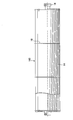
- FIG. 2 is a front view of the cross flow fan 100 according to the first embodiment when viewed from a direction orthogonal to the direction of the rotating shaft 16.
- the cross flow fan 100 is a cylindrical type, and has a feature of sucking air from a direction perpendicular to the rotation shaft 16 and blowing out a plane flow.
- the cross flow fan 100 is used as a blower such as an air conditioner, an air swing fan, an air purifier, and a window fan.
- the cross flow fan 100 includes at least a pair of circular holding plates 10 arranged at intervals in the axial direction, and FIG. 5 formed on the outer periphery of the holding plate 10. And a blade 14 inserted into a plurality of arcuate holes 12 shown.
- the axial direction is a direction in which the rotating shaft 16 extends.
- a rotating shaft 16 is attached to the holding plate 10. When the rotary shaft 16 is driven to rotate, the holding plate 10 rotates together with the plurality of vanes 14. When the rotary shaft 16 is rotationally driven, the cross flow fan 100 functions as a blower.
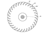
- FIG. 3 is a front view of the holding plate 10 ′ used in the cross flow fan 100 according to the first embodiment when viewed from the direction of the rotating shaft 16.
- FIG. 4 is an enlarged view of an arcuate hole 12 ′ of the holding plate 10 ′ of FIG. 3 and 4 show the holding plate 10 'before the blade plate 14 is fixed.
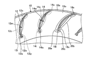
- FIG. 5 is a front view of a part of the holding plate 10 in which the arcuate blade 14 is inserted and fixed in the arcuate hole 12 from the direction of the rotating shaft 16.
- FIG. 5 shows the holding plate 10 in a state after the blade plate 14 is fixed. 3, 4, and 5, reference numerals are given only to some parts, and reference numerals are omitted for other parts.
- a plurality of arc-shaped holes 12 ′ arranged on the circumference around the rotation center of the rotation shaft 16 are formed in the outer peripheral portion 10 o ′ of the holding plate 10 ′.
- the outer peripheral portion 10o ′ is a region where a plurality of arc-shaped holes 12 ′ are formed.
- the holding plate 10 ' is in a state where the blade plate 14 is not fixed to the hole 12'.
- the blade 14 is a plate-like member extending in the first direction, and the dimension in the first direction is larger than the dimension in the direction orthogonal to the first direction.
- the first direction of the blade plate 14 is appropriately referred to as a longitudinal direction.
- the hole 12 ′ has a shape similar to the cross-sectional shape when the blade plate 14 is cut along a plane orthogonal to the longitudinal direction of the blade plate 14.
- the holding plate 10 ′ has an outer peripheral edge region 10 e ′ in a region radially outward from the outer peripheral portion 10 o ′.
- the outer peripheral edge region 10e ′ is in contact with the hole 12 ′.
- the outer peripheral edge region 10e ′ includes the edge of the holding plate 10 ′. Therefore, the arc-shaped hole 12 ′ is completely closed.
- the hole 12 ′ has an inner peripheral side 12 i ′, an outer peripheral side 12 o ′, and a central region 12 c ′.
- the inner peripheral side 12i ′ is a portion in the inner peripheral side region of the outer peripheral portion 10o ′ in the hole 12 ′.
- the outer peripheral side 12o ′ is a portion in the outer peripheral side region of the outer peripheral portion 10o ′ in the hole 12 ′.
- the central region 12c ′ is a portion between the inner peripheral side 12i ′ and the outer peripheral side 12o ′ in the hole 12 ′.
- the width 12w ′ is the width of the hole 12 ′.
- the width 12w ′ of the hole 12 ′ is a width in a direction perpendicular to the arcuate direction of the hole 12 ′ and parallel to the plate surface of the holding plate 10 ′.
- the width 12w ′ is shown in the central region 12c ′, but in this specification, the width 12w is set for all the widths of the holes 12 ′ in the inner peripheral side 12i ′, the outer peripheral side 12o ′, and the central region 12c ′. A description will be given using '.
- the shape of the blade 14 is an arc when viewed from the longitudinal direction.
- the vane plate 14 has a convex curved surface on one surface and a concave curved surface on the other surface.
- board thickness 14w of the blade 14 shown in FIG. 5 is constant along the direction extended in circular arc shape.
- the plate thickness 14w of the wing plate 14 may change along a direction extending in an arc shape.
- the plate thickness 14 w is a dimension of the blade plate 14 in a direction perpendicular to the plate surface of the blade plate 14.
- the width 12w ′ is larger than the plate thickness 14w of the blade 14 at any position in the direction extending in the arc. Therefore, the wing plate 14 can be inserted into the hole 12 '.
- an inner peripheral surface which is a surface facing the convex curved surface of the blade plate 14 to be inserted has a concave curve shape along the convex curved surface of the blade plate 14.
- the hole 12 ′ has a width 12 w ′ wider than the convex curve shape along the concave curved surface of the blade plate 14 on the inner peripheral surface that is the surface facing the concave curved surface of the blade plate 14 to be inserted. It is preferable to have a portion.
- the inner peripheral surface of the hole 12 ′ in the central region 12 c ′ on the side facing the concave curved surface of the blade 14 to be inserted has a linear shape.
- the hole 12 ′ is preferable because it can be easily processed and the width 12w ′ in the central region 12c ′ can be easily widened.
- the hole 12 ′ has a recess 12 ix ′ and a convex portion 12 iy ′ on the inner peripheral surface on the inner peripheral side 12 i ′ opposite to the concave curved surface of the blade 14 to be inserted.
- the recess 12ix ′ is provided close to the tip 12is ′ on the inner peripheral side 12i ′ of the hole 12 ′.
- Convex part 12ii ' is provided adjacent to hollow 12ix'. Since the hole 12 ′ has a depression 12 ix ′, when the blade 14 is inserted into the hole 12 ′, the concave curved surface side portion of the tip 14 is on the inner peripheral side 14 i of the blade 14 shown in FIG.
- the recess 12ix ′ allows the tip 14is on the inner peripheral side 14i of the blade plate 14 to easily contact the tip 12is ′ on the inner peripheral side 12i ′ of the hole 12 ′.
- the hole 12 ′ can improve the accuracy of the position of the tip 14 is on the inner peripheral side 14 i of the blade 14 to be inserted.
- the wing plate 14 is inserted into the hole 12 ′ and the outer peripheral edge region 10 e ′ is crushed toward the wing plate 14, whereby the holding plate 10 ′ is deformed, and the wing plate 14 is inserted into the hole 12 and fixed.
- the holding plate 10 becomes.
- the outer peripheral edge area 10e ′ is deformed by being crushed toward the blade plate 14, and becomes the outer peripheral edge area 10e.
- the hole 12' is deformed and becomes the hole 12 into which the blade plate 14 is inserted and fixed.
- the wing plate 14 is inserted into the hole 12 ′ and the outer peripheral edge region 10 e ′ is crushed toward the wing plate 14, whereby the inner peripheral side 12 i ′, the outer peripheral side 12 o ′, and the central region 12 c ′ are deformed. These are the inner peripheral side 12i, the outer peripheral side 12o, and the central region 12c shown in FIG.
- the wing plate 14 is inserted into the hole 12 ′ and the outer peripheral edge region 10 e ′ is crushed toward the wing plate 14, whereby the dent 12 ix ′ and the convex portion 12 ii ′ are respectively shown in FIG. It becomes the convex part 12ii.
- the blade 12 is inserted into the hole 12 'and the outer peripheral edge region 10e' is crushed toward the blade 14 so that the width 12w 'of the hole 12' is changed to the width 12w of the hole 12 shown in FIG. Change.
- a plurality of arc-shaped holes 12 arranged on the circumference centering on the rotation center of the rotation shaft 16 are formed in the outer peripheral portion 10 o of the holding plate 10. That is, the outer peripheral portion 10o is a region where a plurality of arc-shaped holes 12 are formed.
- the holding plate 10 is in a state where the blade plate 14 is fixed to the hole 12.
- the hole 12 has a shape similar to the shape seen from the axial direction of the blade 14.
- the holding plate 10 has an outer peripheral edge region 10e in a region on the outer peripheral side with respect to the outer peripheral portion 10o.
- the outer peripheral edge region 10 e includes the edge of the holding plate 10. Therefore, the arc-shaped hole 12 is completely closed.
- the hole 12 has an inner peripheral side 12i, an outer peripheral side 12o, and a central region 12c.
- the inner peripheral side 12i is a portion in a region on the inner peripheral side of the hole 12 in the outer peripheral portion 10o.
- the outer peripheral side 12o is a portion in the region on the outer peripheral side of the hole 12 in the outer peripheral portion 10o.
- the central region 12c is a portion between the inner peripheral side 12i and the outer peripheral side 12o.
- the width 12w is the width of the hole 12 in the central region 12c.
- the width of the hole 12 is a width in a direction perpendicular to the direction in which the hole 12 extends in an arc shape. In FIG. 5, the width 12w is shown in the central region 12c, but in this specification, all the widths of the holes 12 in the inner peripheral side 12i, the outer peripheral side 12o, and the central region 12c will be described using the width 12w.
- the blade 14 inserted into the hole 12 and fixed has an inner peripheral side 14i, an outer peripheral side 14o, and a central region 14c.
- the inner peripheral side 14i is a portion arranged in a region on the inner peripheral side of the outer peripheral portion 10o in the blade plate 14. That is, the inner peripheral side 14 i of the wing plate 14 is disposed on the inner peripheral side 12 i of the hole 12.
- the outer peripheral side 14o is a part arranged in the outer peripheral side region of the outer peripheral portion 10o in the blade plate 14. That is, the outer peripheral side 14 o of the blade plate 14 is disposed on the outer peripheral side 12 o of the hole 12.
- the central region 14c is a portion disposed between the inner peripheral side 12i and the outer peripheral side 12o in the blade plate 14. That is, the central region 14 c of the blade 14 is disposed in the central region 12 c of the hole 12.
- the width 12w of the hole 12 in the central region 12c is larger than the plate thickness 14w of the blade plate 14.
- the width of the hole 12 is a dimension in a direction perpendicular to the direction in which the hole 12 extends in an arc shape and parallel to the plate surface of the holding plate 10.
- the holding plate 10 has, on the inner peripheral surface of the hole 12, a first contact portion 18i, a second contact portion 18o, and a third contact portion 18c on which the blade plate 14 is supported in contact with the holding plate 10.
- the holding plate 10 has, on the inner peripheral surface of the hole 12, a first non-contact portion 20a, a second non-contact portion 20b, and a third non-contact portion 20c where the blade plate 14 does not contact the holding plate 10.
- the blade 14 is supported and fixed by the first contact portion 18i, the second contact portion 18o, and the third contact portion 18c.
- the first contact portion 18 i is formed on the inner peripheral side 12 i of the inner peripheral surface of the hole 12.
- the first contact portion 18 i is a region where the tip 14 is on the inner peripheral side 14 i of the blade 14 is fixed by the tip 12 is on the inner peripheral side 12 i of the hole 12.
- the holding plate 10 fixes and supports the tip 14is on the inner peripheral side 14i of the blade plate 14 at the first contact portion 18i.
- the outer peripheral edge region 10e ' is crushed toward the blade 14 so that the tip 14is on the inner peripheral side 14i of the blade 14 is in the inner periphery of the hole 12'. It is pressed against the tip 12is 'of the side 12i'.
- the tip 12is ′ becomes the tip 12is when the tip 14is is pressed.
- the first contact portion 18i is formed on the tip 12is by the tip 12is' becoming the tip 12is.
- the second contact portion 18 o is formed on the outer peripheral side 12 o on the inner peripheral surface of the hole 12.
- the second contact portion 18 o is a region where the outer peripheral side 14 o of the blade plate 14 is fixed on the outer peripheral side 12 o of the hole 12.
- the holding plate 10 fixes and supports the outer peripheral side 14o of the blade 14 at the second contact portion 18o.
- the outer peripheral edge region 10 e ′ is crushed toward the wing plate 14, whereby the outer peripheral side 12 o ′ of the hole 12 ′ is deformed and the outer peripheral side 14 o of the wing plate 14 is deformed.
- the outer peripheral side 12o of the hole 12 having a shape along There is no gap between the outer peripheral side 14o of the blade 14 and the outer peripheral side 12o of the hole 12.
- the second contact portion 18o is deformed on the outer peripheral side 12o 'of the hole 12' and becomes the outer peripheral side 12o of the hole 12 having a shape along the outer peripheral side 14o of the blade plate 14, so that the outer peripheral side 12o of the hole 12 It is formed.
- the third contact portion 18 c is formed on the inner peripheral side 12 i on the inner peripheral surface of the hole 12.
- the third contact portion 18 c is a region in which a part of the concave curved surface on the inner peripheral side 14 i of the blade plate 14 is fixed by the convex portion 12 iy of the hole 12.
- the holding plate 10 fixes and supports a part of the concave curved surface on the inner peripheral side 14i of the blade plate 14 at the third contact portion 18c.
- the outer peripheral edge region 10 e ′ is crushed toward the blade 14, whereby the convex portion 12 iy ′ of the hole 12 ′ becomes the convex portion 12 iy.
- the convex portion 12iy can improve the accuracy of the position of the tip 14is on the inner peripheral side 14i of the wing plate 14.
- the 3rd contact part 18c is formed in the convex part 12iy because the convex part 12ii 'of hole 12' turns into the convex part 12iy.
- the first non-contact part 20a is formed on the side of the inner peripheral surface of the hole 12 that faces the convex curved surface of the blade 14 in the region between the first contact part 18i and the second contact part 18o. Yes.
- the first non-contact portion 20a includes a side of the central region 12c that faces the convex curved surface of the blade plate 14.
- the first non-contact portion 20a includes a side of the inner peripheral side 12i that faces the curved surface on the convex side of the blade plate 14 with respect to the tip 12is.
- the first non-contact portion 20 a is a region where a gap is secured between the inner peripheral surface of the hole 12 and the blade 14.
- the inner peripheral surface of the hole 12 in the first non-contact portion 20 a has a concave curve shape along the convex curved surface of the blade plate 14.
- the first non-contact portion 20a is formed when the outer peripheral edge region 10e 'is crushed toward the blade plate 14 to form the first contact portion 18i and the second contact portion 18o.
- the second non-contact part 20b is formed on the inner surface of the hole 12 between the first contact part 18i and the second contact part 18o on the side facing the concave curved surface of the blade plate 14. Yes. Specifically, the second non-contact portion 20b is a side facing the concave curved surface of the blade plate 14 in the region between the second contact portion 18o and the third contact portion 18c on the inner peripheral surface of the hole 12. Is formed. The second non-contact portion 20b includes a side facing the concave curved surface of the blade 14 in the central region 12c. The second non-contact portion 20 b is a region where a gap is secured between the inner peripheral surface of the hole 12 and the blade 14. The first non-contact portion 20a is formed by forming the first contact portion 18i, the second contact portion 18o, and the third contact portion 18c by crushing the outer peripheral edge region 10e 'toward the blade plate 14. ,It is formed.
- the inner peripheral surface of the hole 12 in the second non-contact portion 20b is a region that does not contribute to the holding of the blade plate 14, the clearance between the inner peripheral surface of the hole 12 and the blade plate 14 should be ensured. Any shape is possible.
- the inner peripheral surface of the hole 12 in the second non-contact portion 20b has a linear shape.
- the inner peripheral surface of the hole 12 in the second non-contact portion 20b may have a shape that approximates a linear shape.
- the third non-contact portion 20c is formed on the side of the inner peripheral surface of the hole 12 that faces the concave curved surface of the blade 14 in the region between the first contact portion 18i and the second contact portion 18o. Yes. Specifically, the third non-contact portion 20c is the side of the inner peripheral surface of the hole 12 that faces the concave curved surface of the blade 14 in the region between the first contact portion 18i and the third contact portion 18c. Is formed.
- the third non-contact portion 20 c includes a side of the inner peripheral side 12 i that faces the curved surface on the concave side of the blade plate 14. More specifically, the third non-contact portion 20 c is formed in the region of the recess 12 ix on the inner peripheral surface of the hole 12.
- the third non-contact portion 20 c is a region where a gap is secured between the inner peripheral surface of the hole 12 and the blade plate 14.
- the depression 12ix can improve the accuracy of the position of the tip 14is on the inner peripheral side 14i of the blade plate 14.
- the third non-contact portion 20c is formed by forming the first contact portion 18i, the second contact portion 18o, and the third contact portion 18c by crushing the outer peripheral edge region 10e 'toward the blade plate 14. It is formed.
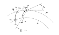
- FIG. 6 is an explanatory diagram of important parameters that determine the blowing performance of the blade 14 used in the crossflow fan 100 according to the first embodiment.
- the specific shape of the blade 14 is determined according to the air blowing performance required for the blade 14.
- Important parameters that determine the air blowing performance of the blade 14 include the exit angle ⁇ o, the mounting angle ⁇ i, the blade inner diameter, and the blade outer diameter.
- the blade inner diameter is the diameter of the inner peripheral surface Ri of the blade 14.
- the inner peripheral surface Ri of the blade plate 14 is such that the tip 14 is on the inner peripheral side 14 i of the blade plate 14 is the center of rotation of the rotary shaft 16 shown in FIGS. 1 and 2. It is a cylindrical surface drawn around the center.
- the blade outer diameter is the diameter of the outer peripheral surface Ro of the blade 14.
- the outer peripheral surface Ro of the blade plate 14 is such that the tip 14os on the outer peripheral side 14o of the blade plate 14 is centered on the rotation center of the rotary shaft 16 shown in FIGS. It is a cylindrical surface drawn as
- the exit angle ⁇ o is directed to the tip 14 os of the outer peripheral side 14 o of the blade plate 14 with respect to the tangent line of the outer peripheral surface Ro of the blade plate 14 at the tip 14 os of the outer peripheral side 14 o of the blade plate 14.
- the mounting angle ⁇ i is based on a straight line connecting the tip 14os on the outer peripheral side 14o of the blade 14 and the rotation center of the rotating shaft 16 shown in FIGS. The angle of the straight line connecting the tip 14os of the outer peripheral side 14o and the tip 14is of the inner peripheral side 14i of the wing plate 14.
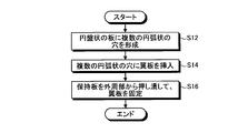
- FIG. 7 is a flowchart showing an example of a manufacturing method of the cross flow fan 100 according to the first embodiment.
- the method of manufacturing the cross flow fan 100 according to the first embodiment includes the hole forming step S12, the blade plate inserting step S14, and the blade plate fixing step S16.
- the hole formation step S12 is simply referred to as step S12
- the blade plate insertion step S14 is simply referred to as step S14
- the blade plate fixing step S16 is simply referred to as step S16.
- a plurality of arc-shaped holes 12 ′ into which the blades 14 can be inserted are formed in the outer peripheral portion 10 o ′ of the disk-shaped plate that is the material of the holding plate 10 ′ (step S 12).
- the disc-shaped plate becomes the holding plate 10 ′ by forming the hole 12 ′ in step S ⁇ b> 12.
- step S ⁇ b> 12 the width 12 w ′ of the hole 12 ′ at any position in the direction extending in the arc shape is formed larger than the plate thickness 14 w of the blade plate 14.
- the inner peripheral surface of the hole 12 ′ on the side facing the convex curved surface of the blade plate 14 to be inserted is formed in a concave curve shape along the convex curved surface of the blade plate 14.
- the inner peripheral surface of the hole 12 'on the side facing the concave curved surface of the blade plate 14 to be inserted has a width 12w' wider than the convex curve shape along the concave curved surface of the blade plate 14. It is preferable to be formed in a given shape. Specifically, in step S12, it is preferable that the inner peripheral surface in the central region 12c ′ on the side facing the concave curved surface of the blade 14 to be inserted is formed in a linear shape.
- step S12 it is preferable that a recess 12ix ′ and a convex portion 12ii ′ are formed on the inner peripheral surface on the inner peripheral side 12i ′ on the side facing the concave curved surface of the blade 14 to be inserted.
- step S12 A single blade 14 is inserted into each of the plurality of arcuate holes 12 'formed in step S12 (step S14).
- step S12 since the width 12w 'of the hole 12' is formed larger than the plate thickness 14w of the blade plate 14, in step S14, the blade plate 14 is easily inserted into the hole 12 '.
- step S12 the inner peripheral surface of the hole 12 'on the side facing the convex curved surface of the blade plate 14 to be inserted is formed in a concave curved shape along the convex curved surface of the blade plate 14. Therefore, when the blade 14 is inserted into the hole 12 ′ in step S ⁇ b> 14, the region formed in the concave curve shape on the inner peripheral surface of the hole 12 ′ and the curved surface on the convex side of the blade 14 are opposed to each other.
- the inner peripheral surface of the hole 12 'on the side facing the concave curved surface of the blade plate 14 to be inserted has a convex curve shape along the concave curved surface of the blade plate 14.
- the width 12w ′ is formed in an expanded shape. Therefore, the blade 14 can be easily inserted into the hole 12 '.
- the blade plate 14 is inserted into the hole 12 ′ in step S ⁇ b> 14, so that the linearly formed region on the inner peripheral surface of the hole 12 ′ and the concave curved surface of the blade plate 14 face each other.
- a recess 12ix ′ and a convex portion 12ii ′ are formed on the inner peripheral surface on the inner peripheral side 12i ′ on the side facing the concave curved surface of the blade 14 to be inserted.
- the concave curved surface portion of the tip 14 is on the inner peripheral side 14 i of the blade 14 can escape into the recess 12 ix ′.
- the tip 14is of the inner peripheral side 14i of the blade 14 is easily changed to the tip 12is' of the inner peripheral side 12i 'of the hole 12'.
- the accuracy of the position of the tip 14is on the inner peripheral side 14i of the blade 14 to be inserted is improved.
- the holding plate 10 ' is deformed and the blade plate 14 is fixed (step S16).
- the deformed outer peripheral area 10e ′ becomes the outer peripheral area 10e.
- the deformed holding plate 10 ′ becomes the holding plate 10.
- the deformed hole 12 ′ becomes the hole 12.
- the inner peripheral side 12i ', outer peripheral side 12o' and central region 12c 'of the hole 12' are deformed to become the inner peripheral side 12i, outer peripheral side 12o and central region 12c of the hole 12, respectively.
- the depression 12ix ′ becomes the depression 12ix.
- the convex part 12iy ′ becomes the convex part 12iy.
- the width 12 w ′ of the hole 12 ′ changes to the width 12 w of the hole 12.
- step S ⁇ b> 16 the hole 12 ′ is deformed to become the hole 12, whereby the first contact portion 18 i, the second contact portion 18 o, and the third contact that support and fix the blade 14 on the inner peripheral surface of the hole 12. A portion 18c is formed.
- step S ⁇ b> 16 the hole 12 ′ is deformed to become the hole 12, so that the first non-contact part 20 a, the second non-contact part 20 b, and the third non-contact that do not contact the blade 14 are formed on the inner peripheral surface of the hole 12. Part 20c is formed.
- the first contact portion 18i is formed at the tip 12is by setting the tip 12is ′ as the tip 12is.
- the second contact portion 18 o is formed on the outer peripheral side 12 o of the hole 12.
- the convex part 12i becomes the convex part 12iy, whereby the third contact part 18c is formed on the convex part 12iy.
- the convex side of the blade plate 14 in the region between the first contact portion 18 i and the second contact portion 18 o on the inner peripheral surface of the hole 12.
- the first non-contact portion 20a is formed on the side facing the curved surface.
- a second non-contact portion 20b is formed on the side facing the concave curved surface of the blade 14.
- a third non-contact portion 20c is formed on the side facing the concave curved surface of the blade 14.
- the outer peripheral edge region 10 e is formed on the holding plate 10, and the first contact portion 18 i and the second contact where the blade plate 14 is supported by contacting the holding plate 10.
- a portion 18o and a third contact portion 18c are provided.
- the cross flow fan 100 the first non-contact part 20a, the second non-contact part 20b, and the third non-contact part 20c in which the blade 14 does not contact the holding plate 10 are provided on the holding plate 10.
- the cross flow fan 100 reduces the friction of the blade plate 14 with the inside of the hole 12 of the holding plate 10 when the blade plate 14 is rotated around the rotation shaft 16.
- the cross flow fan 100 can reduce minute noise generated when the vane plate 14 is rotated around the rotation center of the rotary shaft 16. For this reason, since the crossflow fan 100 which concerns on Embodiment 1 can suppress the fall of durability of the blade plate 14, it can reduce a running cost.
- the holding plate 10 fixes and supports the tip 14is on the inner peripheral side 14i of the blade plate 14 with the first contact portion 18i, and includes the tip 14os of the blade plate 14 with the second contact portion 18o.
- the outer peripheral side 14o is fixed and supported.
- the cross flow fan 100 has a blade 14 such as an exit angle ⁇ o, a mounting angle ⁇ i, a blade inner diameter, and a blade outer diameter, which are determined by the tip 14is on the inner peripheral side 14i and the tip 14os on the outer peripheral side 14o.
- the important parameter that determines the air blowing performance of the blade can be maintained even when the blade 14 is rotated about the rotation shaft 16. Therefore, the cross flow fan 100 can maintain the blowing performance even when the blade 14 is rotated around the rotation shaft 16.
- the cross flow fan 100 Since the cross flow fan 100 is provided with the depression 12ix ′ in the hole 12 ′ in the manufacturing process, the concave curved surface portion of the tip 14is of the inner peripheral side 14i of the vane plate 14 is depressed 12ix in the blade insertion step S14. You can escape to ⁇ . Accordingly, the cross flow fan 100 can improve the accuracy of the position of the tip 14is on the inner peripheral side 14i of the blade plate 14. Moreover, the cross flow fan 100 can determine the blade inner diameter with high accuracy.
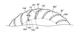
- the cross flow fan 100 is formed with the recess 12ix and the convex portion 12ii, the third contact portion 18c and the third non-contact portion 20c are formed on the holding plate 10. Therefore, the cross flow fan 100 can stably support the blade plate 14 with the holding plate 10.
- FIG. FIG. 8 is a front view of a part of the holding plate 30 ′ used in the cross flow fan according to the second embodiment when viewed from the direction of the rotating shaft 16.
- FIG. 9 is a front view of the holding plate 30 of the crossflow fan according to the second embodiment when viewed from the direction of the rotating shaft 16.
- reference numerals are given only to some parts, and reference numerals are omitted for other parts.
- the crossflow fan according to Embodiment 2 is obtained by changing the holding plate 10 to the holding plate 30 in the crossflow fan 100 according to Embodiment 1.
- the cross flow fan according to the second embodiment uses the same code group as that of the first embodiment in the same configuration as that of the first embodiment, and a detailed description thereof is omitted.
- a plurality of arc-shaped holes 12 ′ arranged on the circumference around the rotation center of the rotation shaft 16 are formed in the outer peripheral portion 30 o ′ of the holding plate 30 ′.
- the outer peripheral portion 30o ′ is a region where a plurality of arc-shaped holes 12 ′ are formed.
- the holding plate 30 ′ is in a state where the blade plate 14 is not fixed to the hole 12 ′.
- the holding plate 30 ′ has an outer peripheral edge region 30 e ′ in a region radially outward from the outer peripheral portion 30 o ′.
- the outer peripheral edge region 30e ′ is in contact with the hole 12 ′.
- the outer peripheral edge region 30e ′ includes the edge of the holding plate 30 ′.
- the outer peripheral edge region 30e ′ has an outer peripheral edge convex portion 32 ′ at the edge of the holding plate 30 ′.
- the holding plate 30 When the blade 14 is inserted into the hole 12 'and the outer peripheral edge region 30e' is crushed toward the blade 14, the holding plate 30 'is deformed, and the blade 14 is inserted into the hole 12 shown in FIG.
- the holding plate 30 is inserted and fixed.
- the outer peripheral area 30e ′ is deformed by being crushed toward the blade plate 14, and becomes an outer peripheral area 30e shown in FIG.
- the outer peripheral convex portion 32 ′ is deformed by being crushed toward the blade 14 and becomes the outer peripheral convex portion 32 shown in FIG. 9.
- the hole 12 ′ When the outer peripheral edge region 30e ′ is crushed toward the blade plate 14, the hole 12 ′ is deformed, and the hole 12 shown in FIG. 9 is inserted and fixed.
- a plurality of arc-shaped holes 12 arranged on the circumference centering on the rotation center of the rotation shaft 16 are formed in the outer peripheral portion 30 o of the holding plate 30. That is, the outer peripheral portion 30o is a region where a plurality of arc-shaped holes 12 are formed.
- the holding plate 30 is in a state where the blade plate 14 is fixed to the hole 12.
- the hole 12 has a shape similar to the shape seen from the axial direction of the blade 14.
- the holding plate 30 has an outer peripheral region 30e in a region on the outer peripheral side of the outer peripheral portion 30o.
- the outer peripheral edge region 30 e includes the edge of the holding plate 30.
- the outer peripheral edge region 30 e has an outer peripheral edge convex portion 32 at the edge of the holding plate 30.
- the crossflow fan manufacturing method according to the second embodiment is obtained by changing the blade plate fixing step S16 in the crossflow fan 100 according to the first embodiment.
- the outer peripheral edge region 30e ′ of the holding plate 30 ′ is crushed toward the blade 14 with respect to the holding plate 30 ′ in which the blade 14 is inserted into the hole 12 ′.
- the holding plate 30 ′ is deformed to fix the blade plate 14.
- the outer peripheral edge convex portion 32 ′ is deformed so as to protrude toward the hole 12 ′ by crushing it toward the blade 14 ′ inserted into the hole 12 ′.
- the deformed outer peripheral convex portion 32 ′ becomes the outer peripheral convex portion 32.
- the deformed outer peripheral edge region 30e ′ becomes the outer peripheral edge region 30e.
- the deformed holding plate 30 ′ becomes the holding plate 30.
- the outer peripheral edge region 30 e is formed on the holding plate 30, and the outer peripheral edge region 30 e has the outer peripheral protrusion 32 on the edge of the holding plate 30.
- the outer peripheral portion 14o of the blade 14 is strongly fixed by the outer peripheral portion 12o of the hole 12. That is, the cross flow fan according to Embodiment 2 has a stronger holding force for the blades 14 of the holding plate 30.
- the cross flow fan according to Embodiment 2 when the blade plate 14 is rotated around the rotation shaft 16, the blade plate 14 moves in the hole 12 of the holding plate 30, for example, the blade plate 14 is moved to the holding plate. The vibration in the 30 holes 12 is further reduced. Further, the cross flow fan according to Embodiment 2 can more strongly maintain the blowing performance when rotating the blade plate 14 around the rotation shaft 16.
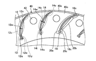
- FIG. 10 is a front view of a part of the holding plate 40 ′ used in the cross flow fan according to the third embodiment when viewed from the direction of the rotating shaft 16.
- FIG. 11 is a front view of the holding plate 40 of the crossflow fan according to the third embodiment as viewed from the direction of the rotating shaft 16.
- reference numerals are given only to some parts, and reference numerals are omitted for other parts.
- the crossflow fan according to Embodiment 3 is obtained by changing the holding plate 10 to the holding plate 40 in the crossflow fan 100 according to Embodiment 1.
- the cross flow fan according to the third embodiment uses the same code group as that of the first embodiment in the same configuration as that of the first embodiment, and a detailed description thereof is omitted.
- a plurality of arc-shaped holes 12 ′ arranged on the circumference around the rotation center of the rotation shaft 16 are formed in the outer peripheral portion 40 o ′ of the holding plate 40 ′.
- the outer peripheral portion 40o ′ is a region where a plurality of arc-shaped holes 12 ′ are formed.
- the holding plate 40 ′ is in a state where the wing plate 14 is not fixed to the hole 12 ′.
- the holding plate 40 ′ has an outer peripheral hole portion 42 ′ in a region in a direction in which the curved surface on the concave side of the blade plate 14 faces the outer peripheral portion 40 o ′ rather than the outer peripheral side 12 o ′ of the hole 12 ′.
- the holding plate 40 ′ has an outer peripheral edge region 40 e ′ in a region on the outer peripheral side than the outer peripheral portion 40 o ′.
- the outer peripheral edge region 40e ′ is in contact with the hole 12 ′.
- the outer peripheral edge region 40e ′ includes the edge of the holding plate 40 ′.
- the holding plate 40 ' is deformed, and the blade 14 is inserted into the hole 12 shown in FIG.
- the holding plate 40 is inserted and fixed.
- the outer peripheral edge region 40 e ′ is crushed toward the blade plate 14, so that the region on the outer peripheral side 12 o ′ from the hole 12 ′ of the holding plate 40 ′ faces the outer peripheral hole portion 42 ′.
- the outer peripheral hole portion 42 ′ is deformed by being crushed toward the blade plate 14, and becomes the outer peripheral hole portion 42 shown in FIG. 11.
- the outer peripheral edge area 40e ′ is deformed by being crushed toward the blade plate 14, and becomes an outer peripheral edge area 40e shown in FIG.
- the hole 12' is deformed, and the hole 12 shown in FIG. 11 is inserted and fixed.
- the wing plate 14 is inserted into the hole 12 ′ and the outer peripheral edge region 40 e ′ is crushed toward the wing plate 14, whereby the inner peripheral side 12 i ′, the outer peripheral side 12 o ′, and the central region 12 c ′ are deformed.
- 11 are the inner peripheral side 12i, the outer peripheral side 12o, and the central region 12c.
- a plurality of arc-shaped holes 12 arranged on the circumference centering on the rotation center of the rotation shaft 16 are formed in the outer peripheral portion 40 o of the holding plate 40. That is, the outer peripheral portion 40o is a region where a plurality of arc-shaped holes 12 are formed.
- the holding plate 40 is in a state where the blade plate 14 is fixed to the hole 12.
- the holding plate 40 has an outer peripheral hole portion 42 in a region in a direction in which the curved surface on the concave side of the blade plate 14 faces the outer peripheral portion 40 o rather than the outer peripheral side 12 o of the hole 12.
- the hole 12 has a shape similar to the shape seen from the axial direction of the blade 14.
- the holding plate 40 has an outer peripheral region 40e in a region on the outer peripheral side with respect to the outer peripheral portion 40o.
- the outer peripheral edge region 40 e includes the edge of the holding plate 40.
- Embodiment 3 A method of manufacturing a cross flow fan according to Embodiment 3 having the above configuration will be described.
- the blade fixing step S16 is changed in the crossflow fan 100 according to the first embodiment.
- the outer peripheral edge region 40e 'of the holding plate 40' is crushed toward the blade 14 with respect to the holding plate 40 'in which the blade 14 is inserted into the hole 12'.
- the holding plate 40 ′ is deformed to fix the blade plate 14.
- the holding plate 40 ′ is crushed toward the blade plate 14 at the outer peripheral edge region 40 e ′, so that the holding plate 40 ′ is located closer to the outer peripheral side 12 o ′ than the hole 12 ′.
- the region is deformed toward the outer peripheral hole portion 42 '.
- the deformed outer peripheral hole portion 42 ′ becomes the outer peripheral hole portion 42.
- the deformed outer peripheral edge region 40e ′ becomes the outer peripheral edge region 40e.
- the deformed holding plate 40 ′ becomes the holding plate 40.
- the crossflow fan according to the third embodiment has the holding plate 40 in a region in the direction in which the curved surface on the concave side of the blade plate 14 faces the outer peripheral side 12o of the hole 12 in the outer peripheral portion 40o.
- An outer peripheral hole portion 42 is provided.
- the crossflow fan according to the third embodiment when the blade plate 14 is rotated around the rotation shaft 16, the blade plate 14 moves in the hole 12 of the holding plate 40, for example, the blade plate 14 is held by the holding plate. The vibration in the 40 holes 12 is further reduced. Further, the cross flow fan according to Embodiment 3 can more strongly maintain the blowing performance when rotating the blade plate 14 around the rotation shaft 16.
- FIG. FIG. 12 is a diagram showing an example of the shape of the end portion in the direction of the rotating shaft 16 of the blade 54 used in the cross flow fan according to the fourth embodiment.
- the crossflow fan according to Embodiment 4 is obtained by replacing the blade 14 with the blade 54 in the crossflow fan 100 according to Embodiment 1.
- the cross flow fan according to the fourth embodiment uses the same code group as that of the first embodiment in the same configuration as that of the first embodiment, and a detailed description thereof is omitted.
- the inner peripheral side 54i and the outer peripheral side 54o of the blade 54 are machined into a chamfered shape at the end in the direction in which the rotation axis extends, that is, the Z direction shown in FIG. That is, the vane plate 54 has a chamfered shape portion 56 processed into a chamfered shape at an end portion in the Z direction.
- the direction in which the rotation axis extends is the first direction described above, and is the longitudinal direction of the blade plate 54.
- the chamfered shape portion 56 monotonously reduces the cross-sectional area of the end region in the Z direction of the blade plate 54 with respect to the cross-sectional area of the central portion in the Z direction of the blade plate 54.
- the cross-sectional area of the end region in the Z direction of the blade plate 54 is the thickness of the blade plate 54 and the length of the blade plate 54 processed into a chamfered shape in the direction orthogonal to the Z direction.
- the product is smaller than the cross-sectional area of the central portion in the Z direction of the blade plate 54. Therefore, the chamfered shape portion 56 makes it possible to easily insert the blade plate 54 into the hole 12 in the blade plate insertion step in the manufacturing method of the cross flow fan. That is, the chamfered shape portion 46 improves the insertability of the blade plate 54 into the hole 12 in the blade plate insertion step in the method of manufacturing the cross flow fan.
- the end portion in the Z direction of the blade plate 54 is processed into a chamfered shape, but is not limited thereto, and may be processed into an arc shape.
- the blade plate 54 has an arc-shaped portion processed into an arc shape at the end in the Z direction. Similar to the chamfered shape portion 56, the arc-shaped portion monotonously reduces the cross-sectional area of the end region in the Z direction of the blade plate 54 relative to the cross-sectional area of the central portion in the Z direction of the blade plate 54. is there. Therefore, similarly to the chamfered shape portion 56, the arc shape portion enables the blade plate 54 to be easily inserted into the hole 12 in the blade plate insertion step in the cross flow fan manufacturing method. That is, like the chamfered shape portion 56, the arc shape portion improves the insertability of the blade plate 54 into the hole 12 in the blade plate insertion step in the cross flow fan manufacturing method.
- the end portion of the blade plate 54 in the extending direction of the rotating shaft is processed into a chamfered shape and processed into an arc shape, but the present invention is limited to this.
- the central region 54c which is the central region between the inner peripheral side and the outer peripheral side, may be processed into a shape protruding from the inner peripheral side 54i and the outer peripheral side 54o.
- the vane plate 54 has a V-shaped portion in which the central region 54c at the end of the vane plate 54 in the extending direction of the rotation shaft protrudes from the inner peripheral side 54i and the outer peripheral side 54o.
- the V-shaped portion monotonously reduces the cross-sectional area of the end region of the blade plate 54 with respect to the cross-sectional area of the central portion of the blade plate 54, similarly to the chamfered shape portion 56 and the arc-shaped portion. .
- the V-shaped portion allows the blade plate 54 to be easily inserted into the hole 12 in the blade plate insertion step in the method of manufacturing the cross flow fan, similarly to the chamfered shape portion 56 and the arc-shaped portion. That is, the V-shaped portion improves the insertability of the blade plate 54 into the hole 12 in the blade plate insertion step in the method of manufacturing the cross flow fan, similarly to the chamfered shape portion 56 and the circular arc shape portion.
- the blade plate 54 has been described as having a substantially uniform plate thickness.
- a blade shape having a thick central portion may be used.
- the shape of the hole 12 may be changed according to the shape of the wing, and the width may be such that the thickest part of the wing of the hole 12 does not contact.
- the configurations shown in the first embodiment, the second embodiment, the third embodiment, and the fourth embodiment show an example of the contents of the present invention, and can be combined with another known technique.
- a part of the configuration can be omitted and changed without departing from the gist of the present invention.
Landscapes
- Engineering & Computer Science (AREA)
- Mechanical Engineering (AREA)
- General Engineering & Computer Science (AREA)
- Structures Of Non-Positive Displacement Pumps (AREA)
Abstract
Description
図1は、実施の形態1に係るクロスフローファン100の斜視図である。図2は、実施の形態1に係るクロスフローファン100を回転軸16の方向と直交する方向から見た正面図である。なお、図1及び図2では、符号を一部の箇所のみに付しており、その他の箇所には符号を省略している。クロスフローファン100は、円筒型であり、回転軸16に垂直な方向から空気を吸い込み、平面流の気流を吹き出す特徴を有するものである。クロスフローファン100は、空気調和機、エアースイングファン、空気清浄機及びウインドウファン等の送風機として、利用される。
図8は、実施の形態2に係るクロスフローファンに用いられる保持板30´の一部を回転軸16の方向から見た正面図である。図9は、実施の形態2に係るクロスフローファンの保持板30を回転軸16の方向から見た正面図である。なお、図8及び図9では、符号を一部の箇所のみに付しており、その他の箇所には符号を省略している。実施の形態2に係るクロスフローファンは、実施の形態1に係るクロスフローファン100において、保持板10が保持板30に変更されたものである。実施の形態2に係るクロスフローファンは、実施の形態1と同様の構成に実施の形態1と同一の符号群を用い、その詳細な説明を省略する。
図10は、実施の形態3に係るクロスフローファンに用いられる保持板40´の一部を回転軸16の方向から見た正面図である。図11は、実施の形態3に係るクロスフローファンの保持板40を回転軸16の方向から見た正面図である。なお、図10及び図11では、符号を一部の箇所のみに付しており、その他の箇所には符号を省略している。実施の形態3に係るクロスフローファンは、実施の形態1に係るクロスフローファン100において、保持板10が保持板40に変更されたものである。実施の形態3に係るクロスフローファンは、実施の形態1と同様の構成に実施の形態1と同一の符号群を用い、その詳細な説明を省略する。
図12は、実施の形態4に係るクロスフローファンに用いられる翼板54の回転軸16の方向における端部の形状の一例を示す図である。実施の形態4に係るクロスフローファンは、実施の形態1に係るクロスフローファン100において、翼板14が翼板54に変更されたものである。実施の形態4に係るクロスフローファンは、実施の形態1と同様の構成に実施の形態1と同一の符号群を用い、その詳細な説明を省略する。
Claims (19)
- 回転軸と、
前記回転軸の延びる方向に間隔を設けて配置された、少なくとも一対の保持板と、
前記保持板の外周部に形成された複数の円弧状の穴に挿入された円弧状の翼板と、を備え、
前記保持板は、前記穴よりも外周側の領域に設けられた外周縁領域と、前記翼板を接触して支持する接触部と、前記翼板と接触しない非接触部と、を有することを特徴とするクロスフローファン。 - 前記接触部は、前記翼板の内周側が、前記穴の内周側に接触して支持される第1接触部と、前記翼板の外周側が、前記穴の外周側に接触して支持される第2接触部と、を含み、
前記第1接触部は、前記翼板の内周側の先端を前記穴の内周側で固定する領域であり、
前記第2接触部は、前記翼板の外周側の領域を前記穴の外周側で固定する領域であり、
前記非接触部は、前記翼板の両面側の前記第1接触部と前記第2接触部との間の領域であることを特徴とする請求項1に記載のクロスフローファン。 - 前記穴における前記翼板の凸側の曲面と対向する領域は、前記翼板の凸側の曲面に沿った形状であり、前記非接触部の一部であることを特徴とする請求項1または請求項2に記載のクロスフローファン。
- 前記穴における前記翼板の凹側の曲面と対向する領域は、直線形状の領域を有し、前記非接触部の一部であることを特徴とする請求項1から請求項3のいずれか1項に記載のクロスフローファン。
- 前記穴における前記翼板の凹側の曲面と対向する領域の内周側に、窪みが設けられていることを特徴とする請求項1から請求項4のいずれか1項に記載のクロスフローファン。
- 前記外周縁領域は、前記回転軸に対して前記穴の外周側がある方向の領域に、外周縁凸部を有することを特徴とする請求項1から請求項5のいずれか1項に記載のクロスフローファン。
- 前記保持板の外周部には、前記穴の外周側よりも前記翼板の凹側の曲面が対向する方向の領域に、外周穴部を有することを特徴とする請求項1から請求項6のいずれか1項に記載のクロスフローファン。
- 前記回転軸の延びる方向における前記翼板の端部は、面取り形状又は円弧形状であることを特徴とする請求項1から請求項7のいずれか1項に記載のクロスフローファン。
- 前記回転軸の延びる方向における前記翼板の端部は、前記翼板の内周側と外周側との間の中央領域が前記内周側及び前記外周側よりも前記回転軸の延びる方向に突き出た形状であることを特徴とする請求項1から請求項7のいずれか1項に記載のクロスフローファン。
- 回転軸と、前記回転軸の延びる方向に間隔を設けて配置された少なくとも一対の保持板と、前記保持板に固定された翼板と、を備えるクロスフローファンの製造方法において、
前記保持板の外周部に、前記翼板が挿入可能な複数の円弧状の穴を形成する穴形成ステップと、
前記複数の円弧状の穴に、前記翼板を挿入する翼板挿入ステップと、
前記保持板の前記穴よりも外周側の領域を前記穴に挿入された前記翼板へ向けて押し潰すことで、前記保持板に、前記翼板が前記保持板に接触して支持される接触部と、前記翼板が前記保持板に接触しない非接触部と、を形成して、前記翼板を前記保持板に固定させる翼板固定ステップと、
を有することを特徴とするクロスフローファンの製造方法。 - 前記穴形成ステップでは、前記穴の幅を、前記翼板の板厚より大きく形成することを特徴とする請求項10に記載のクロスフローファンの製造方法。
- 前記接触部は、前記翼板の内周側が、前記穴の内周側に接触して支持される第1接触部と、前記翼板の外周側が、前記穴の外周側に接触して支持される第2接触部と、を有し、
前記第1接触部は、前記翼板の内周側の先端を前記穴の内周側の先端で固定することで形成され、
前記第2接触部は、前記翼板の外周側の領域を前記穴の外周側の領域で固定することで形成され、
前記非接触部は、前記翼板の両面側の前記第1接触部と前記第2接触部との間に形成されることを特徴とする請求項10または請求項11に記載のクロスフローファンの製造方法。 - 前記穴形成ステップでは、前記翼板固定ステップで前記穴における前記翼板の凸側の曲面と対向する領域を、前記翼板の凸側の曲面に沿った凹曲線形状に形成し、
前記翼板固定ステップは、前記凹曲線形状に形成された領域を前記非接触部の一部に形成することを特徴とする請求項10から請求項12のいずれか1項に記載のクロスフローファンの製造方法。 - 前記穴形成ステップでは、前記翼板固定ステップで前記穴における前記翼板の凹側の曲面と対向する領域を、直線形状の領域を有した形状に形成し、
前記翼板固定ステップは、前記直線形状の領域を前記非接触部の一部に形成することを特徴とする請求項10から請求項13のいずれか1項に記載のクロスフローファンの製造方法。 - 前記穴形成ステップでは、前記翼板固定ステップで前記穴における前記翼板の凹側の曲面と対向する領域の内周側に、窪みを設けることを特徴とする請求項10から請求項14のいずれか1項に記載のクロスフローファンの製造方法。
- 前記保持板の前記穴よりも外周側の領域に外周凸部が設けられ、
前記翼板固定ステップでは、前記外周凸部を前記穴に挿入された前記翼板へ向けて押し潰すことで、前記穴に向けて突出するように変形させることを特徴とする請求項10から請求項15のいずれか1項に記載のクロスフローファンの製造方法。 - 前記保持板の前記穴の外周側よりも前記翼板の凹側の曲面が対向する方向の領域に外周穴部が設けられ、
前記翼板固定ステップは、前記保持板の前記穴よりも外周側の領域を前記外周穴部に向けて変形させることを特徴とする請求項10から請求項16のいずれか1項に記載のクロスフローファンの製造方法。 - 前記回転軸の延びる方向における前記翼板の端部には、面取り形状又は円弧形状が形成されることを特徴とする請求項10から請求項17のいずれか1項に記載のクロスフローファンの製造方法。
- 前記回転軸の延びる方向における前記翼板の端部には、前記翼板の内周側と外周側との間の中央領域が前記内周側及び前記外周側よりも前記回転軸の延びる方向に突き出た形状が形成されることを特徴とする請求項10から請求項17のいずれか1項に記載のクロスフローファンの製造方法。
Priority Applications (7)
| Application Number | Priority Date | Filing Date | Title |
|---|---|---|---|
| HK18116317.2A HK1257511B (en) | 2016-02-26 | Cross-flow fan and method for manufacturing cross-flow fan | |
| CN201680081765.XA CN108700079B (zh) | 2016-02-26 | 2016-02-26 | 横流风扇以及横流风扇的制造方法 |
| SG11201805113TA SG11201805113TA (en) | 2016-02-26 | 2016-02-26 | Cross-flow fan and method for manufacturing cross-flow fan |
| JP2018501548A JP6580247B2 (ja) | 2016-02-26 | 2016-02-26 | クロスフローファン及びクロスフローファンの製造方法 |
| MYPI2018702921A MY176103A (en) | 2016-02-26 | 2016-02-26 | Cross flow fan and method of manufacturing cross flow fan |
| PCT/JP2016/055901 WO2017145383A1 (ja) | 2016-02-26 | 2016-02-26 | クロスフローファン及びクロスフローファンの製造方法 |
| TW105119274A TWI636192B (zh) | 2016-02-26 | 2016-06-20 | 橫流風機及橫流風機之製造方法 |
Applications Claiming Priority (1)
| Application Number | Priority Date | Filing Date | Title |
|---|---|---|---|
| PCT/JP2016/055901 WO2017145383A1 (ja) | 2016-02-26 | 2016-02-26 | クロスフローファン及びクロスフローファンの製造方法 |
Publications (1)
| Publication Number | Publication Date |
|---|---|
| WO2017145383A1 true WO2017145383A1 (ja) | 2017-08-31 |
Family
ID=59686067
Family Applications (1)
| Application Number | Title | Priority Date | Filing Date |
|---|---|---|---|
| PCT/JP2016/055901 Ceased WO2017145383A1 (ja) | 2016-02-26 | 2016-02-26 | クロスフローファン及びクロスフローファンの製造方法 |
Country Status (5)
| Country | Link |
|---|---|
| JP (1) | JP6580247B2 (ja) |
| CN (1) | CN108700079B (ja) |
| SG (1) | SG11201805113TA (ja) |
| TW (1) | TWI636192B (ja) |
| WO (1) | WO2017145383A1 (ja) |
Cited By (1)
| Publication number | Priority date | Publication date | Assignee | Title |
|---|---|---|---|---|
| EP4303445A4 (en) * | 2021-03-01 | 2024-12-25 | Fujitsu General Limited | Blower and indoor unit |
Citations (5)
| Publication number | Priority date | Publication date | Assignee | Title |
|---|---|---|---|---|
| US3385511A (en) * | 1966-08-19 | 1968-05-28 | Lau Blower Co | Blower |
| JPS5041111A (ja) * | 1973-07-20 | 1975-04-15 | ||
| JPS5062705U (ja) * | 1973-10-04 | 1975-06-07 | ||
| JPS5779298A (en) * | 1980-11-04 | 1982-05-18 | Akaishi Kinzoku Kogyo Kk | Blade piece holding plate in cylindrical multi-blade fan |
| JPH09133096A (ja) * | 1995-11-09 | 1997-05-20 | Akaishi Kinzoku Kogyo Kk | 円筒型多翼ファン |
Family Cites Families (2)
| Publication number | Priority date | Publication date | Assignee | Title |
|---|---|---|---|---|
| JP3901200B2 (ja) * | 2005-08-05 | 2007-04-04 | ダイキン工業株式会社 | 樹脂製クロスフローファン及びその製造方法 |
| JP5704139B2 (ja) * | 2012-09-04 | 2015-04-22 | ダイキン工業株式会社 | クロスフローファン |
-
2016
- 2016-02-26 JP JP2018501548A patent/JP6580247B2/ja active Active
- 2016-02-26 CN CN201680081765.XA patent/CN108700079B/zh not_active Expired - Fee Related
- 2016-02-26 WO PCT/JP2016/055901 patent/WO2017145383A1/ja not_active Ceased
- 2016-02-26 SG SG11201805113TA patent/SG11201805113TA/en unknown
- 2016-06-20 TW TW105119274A patent/TWI636192B/zh active
Patent Citations (5)
| Publication number | Priority date | Publication date | Assignee | Title |
|---|---|---|---|---|
| US3385511A (en) * | 1966-08-19 | 1968-05-28 | Lau Blower Co | Blower |
| JPS5041111A (ja) * | 1973-07-20 | 1975-04-15 | ||
| JPS5062705U (ja) * | 1973-10-04 | 1975-06-07 | ||
| JPS5779298A (en) * | 1980-11-04 | 1982-05-18 | Akaishi Kinzoku Kogyo Kk | Blade piece holding plate in cylindrical multi-blade fan |
| JPH09133096A (ja) * | 1995-11-09 | 1997-05-20 | Akaishi Kinzoku Kogyo Kk | 円筒型多翼ファン |
Cited By (2)
| Publication number | Priority date | Publication date | Assignee | Title |
|---|---|---|---|---|
| EP4303445A4 (en) * | 2021-03-01 | 2024-12-25 | Fujitsu General Limited | Blower and indoor unit |
| US12270402B2 (en) | 2021-03-01 | 2025-04-08 | Fujitsu General Limited | Fan and indoor equipment |
Also Published As
| Publication number | Publication date |
|---|---|
| JPWO2017145383A1 (ja) | 2018-07-19 |
| CN108700079B (zh) | 2020-04-17 |
| TW201730437A (zh) | 2017-09-01 |
| JP6580247B2 (ja) | 2019-09-25 |
| HK1257511A1 (zh) | 2019-10-25 |
| SG11201805113TA (en) | 2018-09-27 |
| CN108700079A (zh) | 2018-10-23 |
| TWI636192B (zh) | 2018-09-21 |
Similar Documents
| Publication | Publication Date | Title |
|---|---|---|
| AU2017206193B2 (en) | Axial fan and outdoor unit | |
| CN100507280C (zh) | 高效率轴流式风机 | |
| JP4894902B2 (ja) | 除毛機 | |
| JP2006002762A (ja) | 送風機 | |
| EP1792085B1 (en) | Axial impeller with enhanced flow | |
| CN110730868B (zh) | 螺旋桨式风扇 | |
| EP2403683B1 (en) | Grinding wheel | |
| WO2013100153A1 (ja) | トレランスリング | |
| JP6580247B2 (ja) | クロスフローファン及びクロスフローファンの製造方法 | |
| CN106030117A (zh) | 轴流送风机 | |
| JP6834612B2 (ja) | 真空ポンプの製造方法 | |
| HK1257511B (en) | Cross-flow fan and method for manufacturing cross-flow fan | |
| JP7029625B2 (ja) | ブレード固定装置及びダイシング装置 | |
| JP3902193B2 (ja) | 多翼遠心送風機 | |
| WO2018092875A1 (ja) | 圧縮機、及びそのブレードの製造方法 | |
| JP6886105B2 (ja) | ブレード固定装置及びダイシング装置 | |
| CN101208523A (zh) | 离心式多叶片风机 | |
| JP2022114106A (ja) | 多翼ファン及び室内機 | |
| CN114233679A (zh) | 风扇 | |
| JP2012202263A (ja) | シロッコファン用羽根車及びシロッコファン | |
| JP2013119905A (ja) | 中空回転軸およびそれを用いた送風装置 | |
| JP5991898B2 (ja) | クロスフローファン | |
| JP6997672B2 (ja) | 送風機 | |
| JP2010156210A (ja) | 送風機およびこれを利用する空気調和機 | |
| KR101904789B1 (ko) | 모터 |
Legal Events
| Date | Code | Title | Description |
|---|---|---|---|
| ENP | Entry into the national phase |
Ref document number: 2018501548 Country of ref document: JP Kind code of ref document: A |
|
| WWE | Wipo information: entry into national phase |
Ref document number: 11201805113T Country of ref document: SG |
|
| NENP | Non-entry into the national phase |
Ref country code: DE |
|
| 121 | Ep: the epo has been informed by wipo that ep was designated in this application |
Ref document number: 16891540 Country of ref document: EP Kind code of ref document: A1 |
|
| 122 | Ep: pct application non-entry in european phase |
Ref document number: 16891540 Country of ref document: EP Kind code of ref document: A1 |