WO2017145459A1 - 電力系統接続制御システム、電力系統接続制御方法および電力系統接続制御プログラム - Google Patents
電力系統接続制御システム、電力系統接続制御方法および電力系統接続制御プログラム Download PDFInfo
- Publication number
- WO2017145459A1 WO2017145459A1 PCT/JP2016/084110 JP2016084110W WO2017145459A1 WO 2017145459 A1 WO2017145459 A1 WO 2017145459A1 JP 2016084110 W JP2016084110 W JP 2016084110W WO 2017145459 A1 WO2017145459 A1 WO 2017145459A1
- Authority
- WO
- WIPO (PCT)
- Prior art keywords
- power
- power supply
- amount
- consumer
- connection control
- Prior art date
- Legal status (The legal status is an assumption and is not a legal conclusion. Google has not performed a legal analysis and makes no representation as to the accuracy of the status listed.)
- Ceased
Links
Images


Classifications
-
- H—ELECTRICITY
- H02—GENERATION; CONVERSION OR DISTRIBUTION OF ELECTRIC POWER
- H02J—ELECTRIC POWER NETWORKS; CIRCUIT ARRANGEMENTS OR SYSTEMS FOR SUPPLYING OR DISTRIBUTING ELECTRIC POWER; SYSTEMS FOR STORING ELECTRIC ENERGY
- H02J3/00—Circuit arrangements for AC mains or AC distribution networks
-
- H—ELECTRICITY
- H02—GENERATION; CONVERSION OR DISTRIBUTION OF ELECTRIC POWER
- H02J—ELECTRIC POWER NETWORKS; CIRCUIT ARRANGEMENTS OR SYSTEMS FOR SUPPLYING OR DISTRIBUTING ELECTRIC POWER; SYSTEMS FOR STORING ELECTRIC ENERGY
- H02J13/00—Circuit arrangements for providing remote monitoring or remote control of equipment in a power distribution network
-
- H—ELECTRICITY
- H02—GENERATION; CONVERSION OR DISTRIBUTION OF ELECTRIC POWER
- H02J—ELECTRIC POWER NETWORKS; CIRCUIT ARRANGEMENTS OR SYSTEMS FOR SUPPLYING OR DISTRIBUTING ELECTRIC POWER; SYSTEMS FOR STORING ELECTRIC ENERGY
- H02J3/00—Circuit arrangements for AC mains or AC distribution networks
- H02J3/28—Arrangements for balancing of the load in networks by storage of energy
- H02J3/32—Arrangements for balancing of the load in networks by storage of energy using batteries or super capacitors with converting means
-
- H—ELECTRICITY
- H02—GENERATION; CONVERSION OR DISTRIBUTION OF ELECTRIC POWER
- H02J—ELECTRIC POWER NETWORKS; CIRCUIT ARRANGEMENTS OR SYSTEMS FOR SUPPLYING OR DISTRIBUTING ELECTRIC POWER; SYSTEMS FOR STORING ELECTRIC ENERGY
- H02J3/00—Circuit arrangements for AC mains or AC distribution networks
- H02J3/38—Arrangements for feeding a single network from two or more generators or sources in parallel; Arrangements for feeding already energised networks from additional generators or sources in parallel
-
- Y—GENERAL TAGGING OF NEW TECHNOLOGICAL DEVELOPMENTS; GENERAL TAGGING OF CROSS-SECTIONAL TECHNOLOGIES SPANNING OVER SEVERAL SECTIONS OF THE IPC; TECHNICAL SUBJECTS COVERED BY FORMER USPC CROSS-REFERENCE ART COLLECTIONS [XRACs] AND DIGESTS
- Y02—TECHNOLOGIES OR APPLICATIONS FOR MITIGATION OR ADAPTATION AGAINST CLIMATE CHANGE
- Y02E—REDUCTION OF GREENHOUSE GAS [GHG] EMISSIONS, RELATED TO ENERGY GENERATION, TRANSMISSION OR DISTRIBUTION
- Y02E70/00—Other energy conversion or management systems reducing GHG emissions
- Y02E70/30—Systems combining energy storage with energy generation of non-fossil origin
Definitions
- the present invention relates to, for example, a power system connection control system, a power system connection control method, and a power system connection control program for switching connection between a customer who owns a power generation apparatus and a power system.
- a power generation apparatus for example, a solar power generation apparatus
- a surplus power purchase system has been established, so that electric power generated by a solar power generation device, a wind power generation device, or the like can be sold to an electric power company.
- the generated power may not be sold to the power company.
- output suppression a predetermined amount of power that can be purchased by an electric power company is exceeded (hereinafter referred to as output suppression). For this reason, a consumer may use a storage battery that can temporarily store power that could not be sold.
- Patent Document 1 discloses a power management system that can easily and inexpensively notify that a distributed power source that can be connected to a system can be reconnected after being disconnected from the commercial power system. ing.
- the conventional power management system has the following problems. That is, the power management system disclosed in the above publication does not take into account the power supply / demand situation of one consumer, and simply refers to notification of reconnection after being disconnected from the commercial power system. Just doing. For this reason, even if the power generation amount exceeds the consumption amount in one consumer, it is not possible to release the connection with the power system and reduce the power grid usage cost of the power system.
- An object of the present invention is to provide a power system connection control system and a power system connection control capable of reducing the use cost of the power transmission network by releasing the connection with the power system according to the power supply and demand situation in one consumer.
- a method and a power system connection control program are provided. (Means for solving the problem)
- a power system connection control system according to a first invention is a power system connection control system that controls connection switching between a power supply device owned by a first consumer and a distribution network to which power is supplied from a power company.
- a power amount information acquisition unit, a power supply and demand prediction unit, and a control unit. The power amount information acquisition unit acquires information on the power supply amount in the power supply device.
- the power supply and demand prediction unit predicts the power supply and demand situation in a predetermined time zone based on the information acquired by the power amount information acquisition unit and the amount of power consumed by the first consumer.
- the control unit controls the first switching unit that switches the connection between the power distribution network and the power supply device based on the prediction result in the power supply and demand prediction unit.
- the 1st switching part which connects the electric power supply network which an electric power company supplies electric power, and the electric power supply apparatus which a 1st consumer owns is switched.
- connection / disconnection of the electric power supply apparatus which a 1st consumer owns, and a power distribution network is switched.
- the first consumer means a single consumer, and owns a power supply device that supplies power and a load that consumes power.
- Examples of power supply devices owned by consumers include power generation devices that utilize renewable energy such as solar power generation devices, wind power generation devices, and geothermal power generation devices, generators, heat pumps, electric vehicles, and power storage devices. included.
- the information regarding the power supply amount in the power supply device acquired in the power amount information acquisition unit includes, for example, an estimated value of the power generation amount in a predetermined time zone when the power supply device is a power generation device, If is a storage battery, the current storage amount and the like are included.
- the power supply / demand prediction unit compares the amount of power supplied by the power supply device with the amount of power consumed by the load, and predicts the balance between the demand and supply of power in the first consumer.
- the control unit uses the first switching unit to control whether or not to disconnect the distribution network to which power is supplied from the power company and the power supply device based on the prediction result in the power supply and demand prediction unit.
- a 1st switching part is a connection switching means arrange
- the power supply / demand prediction unit predicts that there is an excess supply, it means that sufficient power is supplied to the power consumption by the load in the first consumer.
- the connection between the network and the power supply device can be disconnected. As a result, the power supplied from the distribution network can be cut off to reduce the electricity bill, and the use cost of the distribution network can be reduced.
- the power system connection control system according to the second invention is the power system connection control system according to the first invention, wherein the power supply and demand prediction unit uses the weather forecast information to include the power generation device included in the power supply device The power generation amount in a predetermined time zone is predicted.
- the power supply and demand prediction unit predicts the amount of power generation in the power supply device (power generation device) using information related to the weather forecast.
- a power system connection control system is the power system connection control system according to the first or second aspect of the present invention, wherein the power supply / demand prediction unit is a current power storage amount of the power storage device included in the power supply device Is used to predict the amount of power stored in the power storage device in a predetermined time period.
- the power storage amount of the current power storage device is used for the power supply / demand prediction in the power supply / demand prediction unit.
- the power supply and demand in the consumer group in a predetermined time zone can be obtained using the current power storage amount of the storage battery together with the estimated value of the power generation amount and the power consumption amount of each power supply device in a predetermined time zone. Can be predicted.
- a power system connection control system according to a fourth aspect of the present invention is the power system connection control system according to any one of the first to third aspects, wherein the power supply and demand prediction unit Based on the data which recorded the power consumption according to a lifestyle pattern, the power consumption in a 1st consumer is estimated.
- the data which recorded the power consumption according to the lifestyle pattern of the 1st consumer is used for estimation of the power consumption in a power supply-and-demand prediction part.
- the first consumer has a life pattern in which the amount of power consumed at night is larger than that during the day, the amount of power generated by the solar power generator is large and the amount of power consumed is low during the daytime. It can be seen that there is a high possibility of surplus power. Therefore, it is possible to detect the time zone in which surplus power is likely to be generated for each consumer, and improve the estimation accuracy of the power consumption.
- a power system connection control system is the power system connection control system according to any one of the first to fourth aspects of the present invention, wherein the power in the power supply device acquired in the power amount information acquisition unit
- the information processing apparatus further includes a storage unit that stores information on the supply amount and a prediction result in the power supply and demand prediction unit.
- the information regarding the power supply amount in the power supply apparatus owned by the first consumer and the prediction result of the power supply and demand prediction unit in the first consumer are stored in the storage unit provided in the system.
- a power system connection control system is the power system connection control system according to any one of the first to fifth aspects, wherein information relating to the power supply device is input by the first consumer. Is done.
- the power supply / demand prediction unit predicts the power supply / demand in the first consumer using the information related to the power supply apparatus input by the first consumer.
- the information related to the input power supply device includes information such as the type of the power supply device, the power generation capacity, the estimated power generation amount based on the weather forecast, the power storage amount of the power storage device, and the full charge capacity of the storage battery.
- a power system connection control method is a power system connection control method for controlling connection switching between a power supply device owned by a first consumer and a distribution network to which power is supplied from a power company. , A power amount information acquisition step, a power supply / demand prediction step, and a control step. The power amount information acquisition step acquires information regarding the power supply amount in the power supply device.
- the power supply / demand prediction step predicts the power supply / demand situation in a predetermined time zone based on the information acquired in the power amount information acquisition step and the power consumption amount of the first consumer.
- the control step controls the first switching unit that switches the connection between the distribution network and the power supply device based on the prediction result in the power supply and demand prediction step.
- the 1st switching part which connects the electric power supply network which an electric power company supplies electric power, and the electric power supply apparatus which a 1st consumer owns is switched.
- connection / disconnection of the electric power supply apparatus which a 1st consumer owns, and a power distribution network is switched.
- the first consumer means a single consumer, and owns a power supply device that supplies power and a load that consumes power.
- Examples of power supply devices owned by consumers include power generation devices that utilize renewable energy such as solar power generation devices, wind power generation devices, and geothermal power generation devices, generators, heat pumps, electric vehicles, and power storage devices. included.
- the information on the power supply amount in the power supply device acquired in the power amount information acquisition step includes, for example, an estimated value of the power generation amount in a predetermined time zone, when the power supply device is a power generation device, If is a storage battery, the current storage amount and the like are included.
- the power supply / demand prediction step compares the amount of power supplied by the power supply device with the amount of power consumed by the load, and predicts the balance between the demand and supply of power in the first consumer.
- the control step uses the first switching unit to control whether or not to disconnect the distribution network to which power is supplied from the power company and the power supply device based on the prediction result in the power supply and demand prediction step.
- a 1st switching part is a connection switching means arrange
- a power system connection control program is a power system connection control program for controlling connection switching between a power supply device owned by a first consumer and a distribution network to which power is supplied from a power company.
- the computer is caused to execute a power system connection control method including a power amount information acquisition step, a power supply and demand prediction step, and a control step.
- the power amount information acquisition step acquires information regarding the power supply amount in the power supply device.
- the power supply / demand prediction step predicts the power supply / demand situation in a predetermined time zone based on the information acquired in the power amount information acquisition step and the power consumption amount of the first consumer.
- the control step controls the first switching unit that switches the connection between the distribution network and the power supply device based on the prediction result in the power supply and demand prediction step.
- the 1st switching part which connects the electric power supply network which an electric power company supplies electric power, and the electric power supply apparatus which a 1st consumer owns is switched.
- connection / disconnection of the electric power supply apparatus which a 1st consumer owns, and a power distribution network is switched.
- the first consumer means a single consumer, and owns a power supply device that supplies power and a load that consumes power.
- Examples of power supply devices owned by consumers include power generation devices that utilize renewable energy such as solar power generation devices, wind power generation devices, and geothermal power generation devices, generators, heat pumps, electric vehicles, and power storage devices. included.
- the information on the power supply amount in the power supply device acquired in the power amount information acquisition step includes, for example, an estimated value of the power generation amount in a predetermined time zone, when the power supply device is a power generation device, If is a storage battery, the current storage amount and the like are included.
- the power supply / demand prediction step compares the amount of power supplied by the power supply device with the amount of power consumed by the load, and predicts the balance between the demand and supply of power in the first consumer.
- the control step uses the first switching unit to control whether or not to disconnect the distribution network to which power is supplied from the power company and the power supply device based on the prediction result in the power supply and demand prediction step.
- a 1st switching part is a connection switching means arrange
- the control part contained in this system if it is a prediction result that the supply is excessive, it means that sufficient power is supplied to the power consumption by the load in the first consumer.
- the connection between the network and the power supply device can be disconnected.
- the power supplied from the distribution network can be cut off to reduce the electricity bill, and the use cost of the distribution network can be reduced. (The invention's effect)
- According to the power system connection control system according to the present invention it is possible to release the connection with the power system and reduce the usage cost of the power transmission network according to the supply and demand situation of power in one consumer.
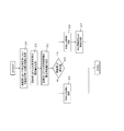
- the block diagram which shows the connection relation of the power grid connection control system which concerns on one Embodiment of this invention, the power supply apparatus which a consumer owns, and a power distribution network.
- the flowchart which shows the flow of the electric power system connection control method performed by the electric power system connection control system of FIG.
- the graph which shows the prediction of the supply-and-demand condition of the electric power in each consumer contained in FIG.
- the figure which shows the predicted value of the electric power supply amount after n hours in each consumer contained in FIG.
- the block diagram which shows the connection relation of the electric power system connection control system which concerns on other embodiment of this invention, the electric power supply apparatus which a consumer owns, and a power distribution network.
- a power system connection control system will be described below with reference to FIGS.
- a customer (first customer) 20 that appears in the following description owns a power generation device (solar panel 21, power storage device 23, and wind power generation device 27) as a power supply device.
- a power generation device solar panel 21, power storage device 23, and wind power generation device 27
- a consumer is, for example, an individual, a corporation, an organization, or the like who has a contract with an electric power company and uses electric power supplied from the electric power company via the grid 40 (see FIG. 1).
- General households detached houses, condominiums), companies (business establishments, factories, facilities, etc.), local governments, national institutions, etc. are included.
- the consumer includes a consumer who provides power by self-power generation and a consumer who realizes ZEB (Zero Energy Building).
- strain 40 means a part of distribution network which supplies the electric power supplied from an electric power company with respect to each consumer.
- the load 24 means a power consumer such as an air conditioner, a refrigerator, a power range, an IH cooking heater, and a television when the consumer is a general household.
- a power consumer such as an air conditioner, a refrigerator, a power range, an IH cooking heater, and a television when the consumer is a general household.
- a consumer when a consumer is a company (a factory or the like), it means power consumers such as various facilities and air conditioning equipment installed in the factory.
- an EMS (Energy Management System) 26 is installed in each consumer, and is a system provided to reduce power consumption in each consumer. I mean.
- the EMS 26 is connected to the power system connection control system 10 via a network.
- the smart meter 28 (see FIG. 1) is a measurement that is installed in each consumer, measures the amount of power consumption, and transmits the measurement result to an electric power company or the like using a communication function. Means equipment. By installing the smart meter 28, the electric power company can accurately grasp the real-time power status of each customer and can automate the meter reading work performed every predetermined period.
- the power system connection control system 10 predicts the power supply / demand situation in a customer who owns a power supply device (a power generation device, a power storage device, etc.), and a plurality of switching units 41, 42a ⁇ shown in FIG.
- the connection between the customer (first customer) 20 and the system 40 is cut while switching between 42d and 43a to 43d.
- the power system connection control system 10 detects the power supply / demand situation in the consumer 20 at predetermined time intervals, and based on the demand / supply situation, the switching units 41, 42a to 42d, 43a to 43d. Control to switch between. That is, in the power system connection control system 10 of the present embodiment, when the power supply / demand situation is an excessive supply situation in the consumer 20, the commercial power is supplied to the consumer 20 from the power company. The connection with the system 40 is disconnected (disconnected).
- the power supply device (solar panel 21, power storage device) owned by the customer 20 is controlled by controlling at least one of the switching units 41, 42a, and 43b to be turned off. 23, the connection between the wind power generator 27) and the distribution network (system 40) is disconnected (disconnected).
- the 2nd switching part 41 shown in FIG. 1 is a connection switching means which switches the connection with the some customer group containing the system
- the second switching units 42a to 42d shown in FIG. 1 are connection switching means for performing connection switching with the system 40 for each consumer group including a plurality of consumers.
- the first switching units 43a to 43d shown in FIG. 1 are connection switching means for performing connection switching with the system 40 for each of a plurality of consumers.
- the customer 20 transmits information on the power supply / demand situation of the customer 20 for each predetermined time zone to the power system connection control system 10 via an EMS (Energy Management System) 26.
- EMS Electronicgy Management System
- the consumer 20 includes a solar panel (power supply device) 21, a solar power generation power conversion device (PCS) 22, a power generation power sensor 22 a, a power storage device 23, and power for stored power.
- a sensor 23a, a load 24, a load power sensor 24a, a distribution board 25, an EMS 26, a wind power generation device (power supply device) 27, a wind power generation power sensor 27a, and a smart meter 28 are provided.
- the solar panel (power supply device) 21 is a power generation device that generates electricity using the photovoltaic effect using the light energy of sunlight, and is installed on the roof or the like of the customer 20. And the electric power generation amount in the solar panel 21 can be estimated based on the information regarding the sunshine time of a weather forecast.
- a photovoltaic power generation converter (PCS (Power Conditioning System)) 22 is connected to a solar panel 21 and converts a direct current generated in the solar panel 21 into an alternating current.
- the generated power sensor 22 a is connected to the solar power converter 22 and measures the amount of power generated by the solar panel 21.
- the generated power sensor 22 a transmits the measurement result (power generation amount) to the EMS 26.
- the power storage device (power supply device) 23 is provided for temporarily storing surplus power that cannot be consumed by the load 24 among the power generated by the solar panel 21 and the wind power generator 27. As a result, for example, even when the amount of power consumed by the load 24 is small during the daytime when power is generated by the solar panel 21 and the wind power generator 27, power is generated by storing excess power in the power storage device 23. Eliminating the waste of power.
- the stored power sensor 23 a is connected to the power storage device 23 and measures the amount of power stored in the power storage device 23. Then, the power sensor 23a for stored power transmits a measurement result (amount of stored power) to the EMS 26.
- the load 24 means a power consumer such as an air conditioner or a home appliance such as a refrigerator in a general household, equipment in a factory, or an air conditioner. The load 24 consumes any of the power supplied from the grid 40, the power generated by the solar panel 21, the wind power generator 27, and the power stored in the power storage device 23.
- the load power sensor 24 a is connected to the load 24 and measures the amount of power consumed by the load 24. Then, the load power sensor 24 a transmits the measurement result (power consumption amount) to the EMS 26.
- the distribution board 25 is connected to a power sensor for generated power 22a, a power sensor for stored power 23a, a power sensor for load 24a, and a power sensor for wind power generation 27a. The distribution board 25 supplies the load 24 with the power generated by the solar panel 21 and the wind power generator 27 and the power stored in the power storage device 23.
- the EMS (Energy Management System) 26 is an energy management system provided to reduce power consumption in the consumer 20, and as shown in FIG. 1, each sensor 22a, 23a, 24a. , 27a. Further, the EMS 26 efficiently supplies the load 24 with the power generated in the solar panel 21 and the wind power generator 27 and the power stored in the power storage device 23 using the detection results received from the sensors 22a, 23a, 24a, and 27a. To do.
- the EMS 26 transmits information (demand condition, supply condition) regarding the power supply / demand situation for each predetermined time period in the customer 20 to the power amount information acquisition unit 11 of the power system connection control system 10. Specifically, the EMS 26 receives the detection results from the sensors 22a, 23a, 24a, and 27a for each predetermined time zone, and the past power consumption according to the weather forecast information and the lifestyle pattern of the customer 20 Send data about
- the wind power generation device (power supply device) 27 is a power generation device that generates electricity by rotating a windmill using natural wind force, and is installed in the premises of the customer 20. And the electric power generation amount in the wind power generator 27 can be estimated based on the information regarding the wind speed of a weather forecast. As shown in FIG. 1, the wind power generation power sensor 27 a is connected to the wind power generation device 27 and measures the amount of power generated by the wind power generation device 27. Then, the wind power generation power sensor 27 a transmits the measurement result (power generation amount) to the EMS 26.
- the smart meter 28 measures the solar panel 21 owned by the customer 20, the power generation amount of the wind power generator 27, the power storage amount of the power storage device 23, and the power consumption amount of the load 24.
- the smart meter 28 is connected to the sensors 22a, 23a, 24a, and 27a via the distribution board 25 as shown in FIG.
- the smart meter 28 has a communication function, and transmits information on the amount of power generation, the amount of electricity stored, and the amount of power consumption in the consumer 20 to the power company.
- the power system connection control system 10 includes a power supply device owned by the customer 20 by controlling the second switching unit 41 and the like in a time zone in which the power supply / demand situation is excessively supplied in the customer 20.
- the connection with the distribution network (system 40) is disconnected (disconnected).
- the power system connection control system 10 includes a power amount information acquisition unit 11, a power supply / demand prediction unit 12, a storage unit 13, and a control unit 14.
- the power amount information acquisition unit 11 acquires information on the power supply / demand situation of the customer 20 from the EMS 26 of the customer 20.
- the information acquired by the power amount information acquisition unit 11 includes the solar panel 21, the power generation capability of the wind power generator 27, information on weather forecast, the current power storage amount of the power storage device 23, and the like.
- the demand information acquired by the power amount information acquisition unit 11 includes data of the power consumption amount that changes according to the type of the load 24 owned by the consumer 20, the lifestyle pattern, and the like.
- the power supply and demand prediction unit 12 predicts the power supply and demand situation for each predetermined time zone in the customer 20 based on the information acquired by the power amount information acquisition unit 11.
- the storage unit 13 acquires the information acquired in the power amount information acquisition unit 11 via the power supply / demand prediction unit 12, acquires the prediction result in the power supply / demand prediction unit 12, and stores these information.
- control unit 14 may be a power supply device and distribution network (system 40) owned by the customer 20, or Any one of the switching units 41, 42a, and 43b is controlled so as to cut off the connection of the power distribution network between the customer 20 and the other customers (second customers) 30a to 30c.
- system 40 power supply device and distribution network
- the control unit 14 performs control so that the first switching unit 43b is turned off. As a result, the customer 20 is disconnected from the distribution network connecting the grid 40 and the other customers 30a to 30c, so that the usage cost of the distribution network can be reduced.
- the control unit 14 turns on the first switching unit 43b and supplies surplus power from other consumers 30a to 30c, or turns on the switching units 41, 42a, and 43b and Control power to be supplied.
- the consumer 20 can reduce the time connected with the system
- step S ⁇ b> 11 the power amount information acquisition unit 11 acquires information necessary for supply and demand prediction for each predetermined time period in the customer 20.
- step S12 the power supply / demand prediction unit 12 uses the information acquired in step S11 to predict the demand amount of power in the customer 20 every predetermined time.
- step S13 the power supply / demand prediction unit 12 uses the information acquired in step S11 to predict the supply amount of power at the customer 20 every predetermined time.
- step S14 the demand amount and supply amount of the electric power in the customer 20 for every predetermined time slot
- step S15 when the condition of supply amount ⁇ demand amount is not satisfied, the process proceeds to step S15.
- step S16 when the condition of supply amount ⁇ demand amount is satisfied, the process proceeds to step S16.
- step S15 since the condition of supply quantity ⁇ demand quantity is not satisfied in the consumer 20, the demand quantity is predicted to exceed the supply quantity. Therefore, in this case, in order to receive power supply from the system 40, the control unit 14 controls the switching units 41, 42a, and 43b so as to maintain the connection with the system 40.
- step S16 since the condition of supply amount ⁇ demand amount is satisfied in the customer 20, the supply amount is predicted to be equal to or greater than the demand amount. Therefore, in this case, since it is not necessary to receive power supply from the system 40, the control unit 14 controls the switching units 41, 42a, and 43b so as to disconnect the connection with the system 40.
- the control unit 14 further includes the other consumers 30a.
- the switching units 41, 42a, and 43b are controlled so as to disconnect the connection to 30c.
- the power system connection control system 10 has the configuration shown in FIG. 1, performs power supply / demand prediction in a predetermined time zone according to the flow shown in FIG. 2, and the supply amount is equal to or greater than the demand amount. In the time zone, the connection with the system 40 is disconnected.
- FIG. 3 shows the supply and demand prediction after n hours for a plurality of consumers.
- the total amount of demand of the four consumers A to D exceeds the supply amount at the present time. Power supply is required.
- the total amount of demand of the four consumers A to D is almost the same as the supply amount after n hours.
- the power supply / demand balance is in a balanced state, and therefore power supply from the grid 40 can be made unnecessary by combining power within the consumer group.
- the demand and the supply are balanced between the customer A and the customer B.
- the consumer A totals the amount of power generated by the solar panel (PV) 21, the wind power generator 27 (100 kwh, 5 kwh), and the amount of power from the power storage device 23 (5 kwh).
- the power storage device 23 5 kwh.
- the consumer A predicts a demand of 110 kwh as the load 24 by adding up the power consumption of the air conditioner (100 kwh) and the lighting (10 kwh). Thereby, the supply-and-demand situation in the consumer A after n hours balances with the demand 110kwh and the supply 110kwh.
- the customer B is expected to supply 10 kwh by adding up the power generation amount (5 kwh, 5 kwh) by the heat pump and the electric vehicle.
- the demand of TV (10 kwh) is estimated as the load 24.
- the supply-and-demand situation in the consumer B after n hours balances with the demand 10kwh and the supply 10kwh.
- the solar panel (PV) 21 the amount of power generated by the wind power generator 27 (40 kwh, 10 kwh), and the amount of power from the power storage device 23 (60 kwh) are totaled. , 110 kwh supply is expected.
- the demand of the washing machine (10 kwh) is predicted as the load 24.
- surplus power is generated at 100 kwh with a demand of 10 kwh and a supply of 110 kwh.
- the customer D does not own the power supply device, and thus is a supply 0.
- the demand-and-supply situation in the customer D after n hours is a demand-excess situation with a demand of 100 kwh and a supply of 0 kwh.
- the consumer D can supply surplus power generated by the consumer C, the supply and demand situation in the consumer group including the consumers A to D can be balanced.
- the switching units 41, 42a, 43b, etc. are turned off for the consumers A to C that are in balance of supply and demand after n hours.
- the connection with the system 40 can be disconnected.
- the consumers A to C can reduce the cost of using the distribution network of the grid 40.
- the control unit 14 may control the first switching units 43a to 43d and the like to allow surplus power generated in the customer C to be accommodated in the customer D that is not in balance between supply and demand.
- the usage cost of the grid 40 cannot be reduced, the usage cost of the power can be reduced by receiving the price of surplus power from the customer D.
- the power system connection control system 110 may be such that the power amount information acquisition unit 111 acquires information directly input by the customer 20 using the electronic terminal 128.
- the electronic terminal 128 is a PC, a tablet terminal, a smartphone, a mobile phone, or the like owned by the consumer 120.
- information necessary for power supply and demand prediction for each predetermined time period is input to the electronic terminal 128 by the consumer 120.
- the electronic terminal 128 is connected to the power system connection control system 110 (power amount information acquisition unit 111) via a communication line.
- the electric energy information acquisition part 111 can acquire the information required in order to estimate the condition of the electric power supply and demand in the consumer 20 for every predetermined time using the information directly input from the consumer 120. .
- the consumer 20 demonstrated and demonstrated the example which owns electric power supply apparatuses, such as the solar panel 21, the electrical storage apparatus 23, and the wind power generator 27.
- the present invention is not limited to this.
- a power supply device owned by a consumer in this system a power generation device, a generator, a heat pump, or the like utilizing renewable energy such as a geothermal power generation device may be used.
- a server external to the power system connection control system, a cloud service, or the like may be used as a storage unit that stores various information.
- the power system connection control system of the present invention has an effect of reducing the usage cost of the power transmission network by releasing the connection with the power system according to the supply and demand situation of power in one consumer. It can be widely applied in communities including consumers who own power supply devices.
- SYMBOLS 10 Electric power system connection control system 11 Electric power amount information acquisition part 12 Electric power supply-and-demand prediction part 13 Memory
Landscapes
- Engineering & Computer Science (AREA)
- Power Engineering (AREA)
- Supply And Distribution Of Alternating Current (AREA)
- Remote Monitoring And Control Of Power-Distribution Networks (AREA)
- Charge And Discharge Circuits For Batteries Or The Like (AREA)
Abstract
電力系統接続制御システム(10)は、電力量情報取得部(11)と、電力需給予測部(12)と、制御部(14)とを備えている。電力量情報取得部(11)は、ソーラーパネル(21)、蓄電装置(23)等における電力供給量に関する情報を取得する。電力需給予測部(12)は、電力量情報取得部(11)において取得された情報と、需要家(20)における消費電力量とに基づいて、所定時間帯における電力の需給状況を予測する。制御部(14)は、電力需給予測部(12)における予測結果に基づいて、配電網とソーラーパネル(21)、蓄電装置(23)等との接続を切り替える第1スイッチング部(43a~43d)を制御する。
Description
本発明は、例えば、発電装置を所有する需要家と電力系統との接続切替を実施する電力系統接続制御システム、電力系統接続制御方法および電力系統接続制御プログラムに関する。
近年、再生可能エネルギーを利用して発電する発電電力装置(例えば、太陽光発電装置)が活用されている。わが国においては、余剰電力買い取り制度が制定されているため、太陽光発電装置や風力発電電装置等で発電された電力を電力会社に売ることができる。
一方、発電した電力を電力会社に売ることができない場合がある。例えば、電力会社が買い取り可能な所定の電力量を超えた場合(以下:出力抑制と示す。)等である。このため、需要家は、売却できなかった電力を一時貯めることが可能な蓄電池を用いることがある。
一方、発電した電力を電力会社に売ることができない場合がある。例えば、電力会社が買い取り可能な所定の電力量を超えた場合(以下:出力抑制と示す。)等である。このため、需要家は、売却できなかった電力を一時貯めることが可能な蓄電池を用いることがある。
しかしながら、蓄電池の残電池容量に対して、発電装置で発電される電力量が多い場合には、発電装置において発電された電力を捨てなければならない場合がある。
例えば、特許文献1には、系列連系可能な分散電源が商用電力系統から解列された後、再接続可能であることを簡易かつ低コストで通知することが可能な電力管理システムについて開示されている。
例えば、特許文献1には、系列連系可能な分散電源が商用電力系統から解列された後、再接続可能であることを簡易かつ低コストで通知することが可能な電力管理システムについて開示されている。
しかしながら、上記従来の電力管理システムでは、以下に示すような問題点を有している。
すなわち、上記公報に開示された電力管理システムでは、1つの需要家における電力の需給状況に関して考慮されておらず、単に、商用電力系統から解列された後の再接続の通知を行うことについて言及しているだけである。このため、1つの需要家内において、発電量が消費量を上回っている場合でも、電力系統との接続を解除して、電力系統の送電網使用コストを削減することはできない。
すなわち、上記公報に開示された電力管理システムでは、1つの需要家における電力の需給状況に関して考慮されておらず、単に、商用電力系統から解列された後の再接続の通知を行うことについて言及しているだけである。このため、1つの需要家内において、発電量が消費量を上回っている場合でも、電力系統との接続を解除して、電力系統の送電網使用コストを削減することはできない。
本発明の課題は、1つの需要家内における電力の需給状況に応じて、電力系統との接続を解除して送電網の使用コストを低減することが可能な電力系統接続制御システム、電力系統接続制御方法および電力系統接続制御プログラムを提供することにある。
(課題を解決するための手段)
第1の発明に係る電力系統接続制御システムは、第1の需要家が所有する電力供給装置と電力会社から電力が供給される配電網との接続切替を制御する電力系統接続制御システムであって、電力量情報取得部と、電力需給予測部と、制御部と、を備えている。電力量情報取得部は、電力供給装置における電力供給量に関する情報を取得する。電力需給予測部は、電力量情報取得部において取得された情報と、第1の需要家における消費電力量とに基づいて、所定時間帯における電力の需給状況を予測する。制御部は、電力需給予測部における予測結果に基づいて、配電網と電力供給装置との接続を切り替える第1スイッチング部を制御する。
ここでは、第1の需要家における電力の需給状況に応じて、電力会社から電力が供給される配電網と第1の需要家が所有する電力供給装置とをつなぐ第1スイッチング部を切り替えるように制御することで、第1の需要家が所有する電力供給装置と配電網との接続/切断を切り替える。
ここで、第1の需要家は、単数の需要家を意味しており、電力を供給する電力供給装置、電力を消費する負荷を所有している。
ここで、第1の需要家は、単数の需要家を意味しており、電力を供給する電力供給装置、電力を消費する負荷を所有している。
なお、需要家が所有する電力供給装置としては、例えば、太陽光発電装置、風力発電装置、地熱発電装置等の再生可能エネルギーを活用した発電装置、発電機、ヒートポンプ、電気自動車、蓄電装置等が含まれる。
また、電力量情報取得部において取得される電力供給装置における電力供給量に関する情報には、例えば、電力供給装置が発電装置である場合には、所定時間帯における発電量の推定値、電力供給装置が蓄電池である場合には現在の蓄電量等が含まれる。
また、電力量情報取得部において取得される電力供給装置における電力供給量に関する情報には、例えば、電力供給装置が発電装置である場合には、所定時間帯における発電量の推定値、電力供給装置が蓄電池である場合には現在の蓄電量等が含まれる。
電力需給予測部は、電力供給装置による供給電力量と負荷による消費電力量とを比較して、第1の需要家における電力の需要と供給のバランスを予測する。
制御部は、電力需給予測部における予測結果に基づいて、電力会社から電力が供給される配電網と電力供給装置との接続を切断するか否かを、第1スイッチング部を用いて制御する。
制御部は、電力需給予測部における予測結果に基づいて、電力会社から電力が供給される配電網と電力供給装置との接続を切断するか否かを、第1スイッチング部を用いて制御する。
第1スイッチング部は、第1の需要家が所有する電力供給装置と配電網との間に配置された接続切替手段であって、本システムに含まれる制御部によって制御される。
これにより、電力需給予測部において供給過剰との予測結果であった場合には、第1の需要家内において負荷による消費電力量に対して十分な電力が供給されていることを意味するため、配電網と電力供給装置との接続を切断することができる。この結果、配電網から供給される電力を遮断して電気料金を削減するとともに、配電網の使用コストを削減することができる。
これにより、電力需給予測部において供給過剰との予測結果であった場合には、第1の需要家内において負荷による消費電力量に対して十分な電力が供給されていることを意味するため、配電網と電力供給装置との接続を切断することができる。この結果、配電網から供給される電力を遮断して電気料金を削減するとともに、配電網の使用コストを削減することができる。
第2の発明に係る電力系統接続制御システムは、第1の発明に係る電力系統接続制御システムであって、電力需給予測部は、天気予報の情報を用いて、電力供給装置に含まれる発電装置による所定時間帯における発電量を予測する。
ここでは、電力需給予測部において、天気予報に関する情報を用いて電力供給装置(発電装置)における発電量を予測する。
ここでは、電力需給予測部において、天気予報に関する情報を用いて電力供給装置(発電装置)における発電量を予測する。
これにより、例えば、電力供給装置が太陽光発電装置の場合には、天気予報の日照時間の情報を用いて、太陽光発電装置による発電量を予測することができる。また、例えば、電力供給装置が風力発電装置の場合には、天気予報の風速の情報を用いて、風力発電装置による発電量を予測することができる。
第3の発明に係る電力系統接続制御システムは、第1または第2の発明に係る電力系統接続制御システムであって、電力需給予測部は、電力供給装置に含まれる蓄電装置の現在の蓄電量を用いて、所定時間帯における蓄電装置の蓄電量を予測する。
第3の発明に係る電力系統接続制御システムは、第1または第2の発明に係る電力系統接続制御システムであって、電力需給予測部は、電力供給装置に含まれる蓄電装置の現在の蓄電量を用いて、所定時間帯における蓄電装置の蓄電量を予測する。
ここでは、電力需給予測部における需給予測に、現在の蓄電装置の蓄電量を用いる。
これにより、例えば、所定時間帯における需要家ごとの電力供給装置の発電量、消費電力量の推定値とともに、現在の蓄電池の蓄電量を用いて、所定時間帯における需要家群内の電力需給を予測することができる。
第4の発明に係る電力系統接続制御システムは、第1から第3の発明のいずれか1つに係る電力系統接続制御システムであって、電力需給予測部は、第1の需要家の過去の生活パターンに応じた消費電力量を記録したデータに基づいて、第1の需要家における消費電力量を推定する。
これにより、例えば、所定時間帯における需要家ごとの電力供給装置の発電量、消費電力量の推定値とともに、現在の蓄電池の蓄電量を用いて、所定時間帯における需要家群内の電力需給を予測することができる。
第4の発明に係る電力系統接続制御システムは、第1から第3の発明のいずれか1つに係る電力系統接続制御システムであって、電力需給予測部は、第1の需要家の過去の生活パターンに応じた消費電力量を記録したデータに基づいて、第1の需要家における消費電力量を推定する。
ここでは、電力需給予測部における消費電力量の推定に、第1の需要家の生活パターンに応じた消費電力量を記録したデータを用いる。
これにより、例えば、第1の需要家が日中よりも夜間の消費電力量が多い生活パターンの場合には、太陽光発電装置による発電量が多く、消費電力量が少ない日中の時間帯に余剰電力が生じる可能性が高いことが分かる。よって、需要家ごとに余剰電力が生じやすい時間帯を検出して、消費電力量の推定精度を向上させることができる。
これにより、例えば、第1の需要家が日中よりも夜間の消費電力量が多い生活パターンの場合には、太陽光発電装置による発電量が多く、消費電力量が少ない日中の時間帯に余剰電力が生じる可能性が高いことが分かる。よって、需要家ごとに余剰電力が生じやすい時間帯を検出して、消費電力量の推定精度を向上させることができる。
第5の発明に係る電力系統接続制御システムは、第1から第4の発明のいずれか1つに係る電力系統接続制御システムであって、電力量情報取得部において取得された電力供給装置における電力供給量に関する情報、および電力需給予測部における予測結果を保存する記憶部を、さらに備えている。
ここでは、第1の需要家が所有する電力供給装置における電力供給量に関する情報、第1の需要家における電力需給予測部の予測結果を、システム内に設けられた記憶部に保存する。
ここでは、第1の需要家が所有する電力供給装置における電力供給量に関する情報、第1の需要家における電力需給予測部の予測結果を、システム内に設けられた記憶部に保存する。
これにより、例えば、所定時間経過ごとに、記憶部に保存された各種情報を用いて、第1の需要家における電力の需給状況を予測して、第1スイッチング部を制御して配電網と電力供給装置との間の接続切替を実施することができる。
第6の発明に係る電力系統接続制御システムは、第1から第5の発明のいずれか1つに係る電力系統接続制御システムであって、電力供給装置に関する情報は、第1の需要家によって入力される。
第6の発明に係る電力系統接続制御システムは、第1から第5の発明のいずれか1つに係る電力系統接続制御システムであって、電力供給装置に関する情報は、第1の需要家によって入力される。
ここでは、第1の需要家によって入力された電力供給装置に関する情報を用いて、電力需給予測部が第1の需要家における電力需給を予測する。
なお、入力される電力供給装置に関する情報としては、電力供給装置の種類、発電能力、天気予報に基づく推定発電量、蓄電装置の蓄電量、蓄電池の満充電容量等の情報が含まれる。
なお、入力される電力供給装置に関する情報としては、電力供給装置の種類、発電能力、天気予報に基づく推定発電量、蓄電装置の蓄電量、蓄電池の満充電容量等の情報が含まれる。
これにより、例えば、PC(Personal Computer)やスマートフォン等の電子端末を用いて第1の需要家から直接入力された情報をそのまま取得して、第1の需要家における電力需給を予測することができる。
第7の発明に係る電力系統接続制御方法は、第1の需要家が所有する電力供給装置と電力会社から電力が供給される配電網との接続切替を制御する電力系統接続制御方法であって、電力量情報取得ステップと、電力需給予測ステップと、制御ステップと、を備えている。電力量情報取得ステップは、電力供給装置における電力供給量に関する情報を取得する。電力需給予測ステップは、電力量情報取得ステップにおいて取得された情報と、第1の需要家における消費電力量とに基づいて、所定時間帯における電力の需給状況を予測する。制御ステップは、電力需給予測ステップにおける予測結果に基づいて、配電網と電力供給装置との接続を切り替える第1スイッチング部を制御する。
第7の発明に係る電力系統接続制御方法は、第1の需要家が所有する電力供給装置と電力会社から電力が供給される配電網との接続切替を制御する電力系統接続制御方法であって、電力量情報取得ステップと、電力需給予測ステップと、制御ステップと、を備えている。電力量情報取得ステップは、電力供給装置における電力供給量に関する情報を取得する。電力需給予測ステップは、電力量情報取得ステップにおいて取得された情報と、第1の需要家における消費電力量とに基づいて、所定時間帯における電力の需給状況を予測する。制御ステップは、電力需給予測ステップにおける予測結果に基づいて、配電網と電力供給装置との接続を切り替える第1スイッチング部を制御する。
ここでは、第1の需要家における電力の需給状況に応じて、電力会社から電力が供給される配電網と第1の需要家が所有する電力供給装置とをつなぐ第1スイッチング部を切り替えるように制御することで、第1の需要家が所有する電力供給装置と配電網との接続/切断を切り替える。
ここで、第1の需要家は、単数の需要家を意味しており、電力を供給する電力供給装置、電力を消費する負荷を所有している。
ここで、第1の需要家は、単数の需要家を意味しており、電力を供給する電力供給装置、電力を消費する負荷を所有している。
なお、需要家が所有する電力供給装置としては、例えば、太陽光発電装置、風力発電装置、地熱発電装置等の再生可能エネルギーを活用した発電装置、発電機、ヒートポンプ、電気自動車、蓄電装置等が含まれる。
また、電力量情報取得ステップにおいて取得される電力供給装置における電力供給量に関する情報には、例えば、電力供給装置が発電装置である場合には、所定時間帯における発電量の推定値、電力供給装置が蓄電池である場合には現在の蓄電量等が含まれる。
また、電力量情報取得ステップにおいて取得される電力供給装置における電力供給量に関する情報には、例えば、電力供給装置が発電装置である場合には、所定時間帯における発電量の推定値、電力供給装置が蓄電池である場合には現在の蓄電量等が含まれる。
電力需給予測ステップは、電力供給装置による供給電力量と負荷による消費電力量とを比較して、第1の需要家における電力の需要と供給のバランスを予測する。
制御ステップは、電力需給予測ステップにおける予測結果に基づいて、電力会社から電力が供給される配電網と電力供給装置との接続を切断するか否かを、第1スイッチング部を用いて制御する。
制御ステップは、電力需給予測ステップにおける予測結果に基づいて、電力会社から電力が供給される配電網と電力供給装置との接続を切断するか否かを、第1スイッチング部を用いて制御する。
第1スイッチング部は、第1の需要家が所有する電力供給装置と配電網との間に配置された接続切替手段であって、本システムに含まれる制御部によって制御される。
これにより、電力需給予測ステップにおいて供給過剰との予測結果であった場合には、第1の需要家内において負荷による消費電力量に対して十分な電力が供給されていることを意味するため、配電網と電力供給装置との接続を切断することができる。この結果、配電網から供給される電力を遮断して電気料金を削減するとともに、配電網の使用コストを削減することができる。
これにより、電力需給予測ステップにおいて供給過剰との予測結果であった場合には、第1の需要家内において負荷による消費電力量に対して十分な電力が供給されていることを意味するため、配電網と電力供給装置との接続を切断することができる。この結果、配電網から供給される電力を遮断して電気料金を削減するとともに、配電網の使用コストを削減することができる。
第8の発明に係る電力系統接続制御プログラムは、第1の需要家が所有する電力供給装置と電力会社から電力が供給される配電網との接続切替を制御する電力系統接続制御プログラムであって、電力量情報取得ステップと、電力需給予測ステップと、制御ステップと、を備えている電力系統接続制御方法をコンピュータに実行させる。電力量情報取得ステップは、電力供給装置における電力供給量に関する情報を取得する。電力需給予測ステップは、電力量情報取得ステップにおいて取得された情報と、第1の需要家における消費電力量とに基づいて、所定時間帯における電力の需給状況を予測する。制御ステップは、電力需給予測ステップにおける予測結果に基づいて、配電網と電力供給装置との接続を切り替える第1スイッチング部を制御する。
ここでは、第1の需要家における電力の需給状況に応じて、電力会社から電力が供給される配電網と第1の需要家が所有する電力供給装置とをつなぐ第1スイッチング部を切り替えるように制御することで、第1の需要家が所有する電力供給装置と配電網との接続/切断を切り替える。
ここで、第1の需要家は、単数の需要家を意味しており、電力を供給する電力供給装置、電力を消費する負荷を所有している。
ここで、第1の需要家は、単数の需要家を意味しており、電力を供給する電力供給装置、電力を消費する負荷を所有している。
なお、需要家が所有する電力供給装置としては、例えば、太陽光発電装置、風力発電装置、地熱発電装置等の再生可能エネルギーを活用した発電装置、発電機、ヒートポンプ、電気自動車、蓄電装置等が含まれる。
また、電力量情報取得ステップにおいて取得される電力供給装置における電力供給量に関する情報には、例えば、電力供給装置が発電装置である場合には、所定時間帯における発電量の推定値、電力供給装置が蓄電池である場合には現在の蓄電量等が含まれる。
また、電力量情報取得ステップにおいて取得される電力供給装置における電力供給量に関する情報には、例えば、電力供給装置が発電装置である場合には、所定時間帯における発電量の推定値、電力供給装置が蓄電池である場合には現在の蓄電量等が含まれる。
電力需給予測ステップは、電力供給装置による供給電力量と負荷による消費電力量とを比較して、第1の需要家における電力の需要と供給のバランスを予測する。
制御ステップは、電力需給予測ステップにおける予測結果に基づいて、電力会社から電力が供給される配電網と電力供給装置との接続を切断するか否かを、第1スイッチング部を用いて制御する。
制御ステップは、電力需給予測ステップにおける予測結果に基づいて、電力会社から電力が供給される配電網と電力供給装置との接続を切断するか否かを、第1スイッチング部を用いて制御する。
第1スイッチング部は、第1の需要家が所有する電力供給装置と配電網との間に配置された接続切替手段であって、本システムに含まれる制御部によって制御される。
これにより、電力需給予測ステップにおいて供給過剰との予測結果であった場合には、第1の需要家内において負荷による消費電力量に対して十分な電力が供給されていることを意味するため、配電網と電力供給装置との接続を切断することができる。この結果、配電網から供給される電力を遮断して電気料金を削減するとともに、配電網の使用コストを削減することができる。
(発明の効果)
本発明に係る電力系統接続制御システムによれば、1つの需要家内における電力の需給状況に応じて、電力系統との接続を解除して送電網の使用コストを低減することができる。
これにより、電力需給予測ステップにおいて供給過剰との予測結果であった場合には、第1の需要家内において負荷による消費電力量に対して十分な電力が供給されていることを意味するため、配電網と電力供給装置との接続を切断することができる。この結果、配電網から供給される電力を遮断して電気料金を削減するとともに、配電網の使用コストを削減することができる。
(発明の効果)
本発明に係る電力系統接続制御システムによれば、1つの需要家内における電力の需給状況に応じて、電力系統との接続を解除して送電網の使用コストを低減することができる。
本発明の一実施形態に係る電力系統接続制御システムについて、図1~図5を用いて説明すれば以下の通りである。
ここで、以下の説明において登場する需要家(第1の需要家)20は、電力供給装置として、発電装置(ソーラーパネル21、蓄電装置23および風力発電装置27)を所有している。
ここで、以下の説明において登場する需要家(第1の需要家)20は、電力供給装置として、発電装置(ソーラーパネル21、蓄電装置23および風力発電装置27)を所有している。
また、需要家とは、例えば、電力会社と契約を結んでおり、電力会社から系統40(図1参照)を介して供給される電力を使用する個人、法人、団体等であって、例えば、一般家庭(戸建て、マンション)、企業(事業所、工場、設備等)、地方自治体、国の機関等が含まれる。なお、需要家には、自家発電によって電力をまかなう需要家、ZEB(Zero Energy Building)を実現した需要家も含まれる。
また、以下の実施形態では、説明の便宜上、需要家20と同じ需要家群のグループに含まれる需要家を複数挙げて説明している。しかし、本発明では、需要家20と同じグループに属する需要家は、1つであってもよい。
また、以下の実施形態において、系統40(図1参照)とは、電力会社から供給される電力を各需要家に対して供給する配電網の一部を意味している。
また、以下の実施形態において、系統40(図1参照)とは、電力会社から供給される電力を各需要家に対して供給する配電網の一部を意味している。
さらに、以下の実施形態において、負荷24(図1参照)とは、例えば、需要家が一般家庭の場合には、エアコン、冷蔵庫、電力レンジ、IHクッキングヒータ、テレビ等の電力消費体を意味している。また、例えば、需要家が企業(工場等)の場合には、工場内に設置された各種設備、空調設備等の電力消費体を意味している。
さらに、以下の実施形態において、EMS(Energy Management System)26(図1参照)とは、各需要家にそれぞれ設置されており、各需要家における消費電力量を削減するために設けられたシステムを意味している。そして、EMS26は、ネットワークを介して電力系統接続制御システム10と接続されている。
さらに、以下の実施形態において、EMS(Energy Management System)26(図1参照)とは、各需要家にそれぞれ設置されており、各需要家における消費電力量を削減するために設けられたシステムを意味している。そして、EMS26は、ネットワークを介して電力系統接続制御システム10と接続されている。
そして、以下の実施形態において、スマートメータ28(図1参照)とは、各需要家にそれぞれ設置され、消費電力量を計測し、通信機能を用いて、計測結果を電力会社等へ送信する計測機器を意味している。スマートメータ28を設置したことにより、電力会社は、各需要家におけるリアルタイムの電力状況を正確に把握できるとともに、所定期間ごとに実施される検針業務を自動化することができる。
(実施形態1)
本実施形態に係る電力系統接続制御システム10は、電力供給装置(発電装置、蓄電装置等)を所有する需要家において電力需給状況を予測して、図1に示す複数のスイッチング部41,42a~42d,43a~43dを切り替えながら、需要家(第1の需要家)20と系統40との接続を切断する。
本実施形態に係る電力系統接続制御システム10は、電力供給装置(発電装置、蓄電装置等)を所有する需要家において電力需給状況を予測して、図1に示す複数のスイッチング部41,42a~42d,43a~43dを切り替えながら、需要家(第1の需要家)20と系統40との接続を切断する。
具体的には、電力系統接続制御システム10は、所定の時間帯ごとに、需要家20内において電力の需給状況を検出し、需給状況に基づいて、スイッチング部41,42a~42d,43a~43dを切り替える制御を行う。
すなわち、本実施形態の電力系統接続制御システム10では、需要家20内において、電力需給状況が供給過剰な状況である場合には、需要家20に対して電力会社から商用電力を供給するための系統40との接続を切断(解列)する。
すなわち、本実施形態の電力系統接続制御システム10では、需要家20内において、電力需給状況が供給過剰な状況である場合には、需要家20に対して電力会社から商用電力を供給するための系統40との接続を切断(解列)する。
具体的には、電力系統接続制御システム10では、スイッチング部41,42a,43bの少なくとも1つがOFFになるように制御することで、需要家20が所有する電力供給装置(ソーラーパネル21、蓄電装置23、風力発電装置27)と配電網(系統40)との接続を切断(解列)する。
ここで、図1に示す第2スイッチング部41は、系統40と複数の需要家を含む複数の需要家群との接続を切り替える接続切替手段である。そして、図1に示す第2スイッチング部42a~42dは、複数の需要家を含む需要家群ごとに、系統40との接続切替を実施するための接続切替手段である。さらに、図1に示す第1スイッチング部43a~43dは、複数の需要家ごとに、系統40との接続切替を実施するための接続切替手段である。
ここで、図1に示す第2スイッチング部41は、系統40と複数の需要家を含む複数の需要家群との接続を切り替える接続切替手段である。そして、図1に示す第2スイッチング部42a~42dは、複数の需要家を含む需要家群ごとに、系統40との接続切替を実施するための接続切替手段である。さらに、図1に示す第1スイッチング部43a~43dは、複数の需要家ごとに、系統40との接続切替を実施するための接続切替手段である。
なお、図1に示す各構成をつなぐ実線は、データ等の情報の流れを示しており、一点鎖線は電気の流れを示している。
また、本実施形態の電力系統接続制御システム10の構成については、後段において詳述する。
(需要家20)
需要家20は、図1に示すように、EMS(Energy Management System)26を介して、電力系統接続制御システム10に対して、所定時間帯ごとの需要家20における電力の需給状況に関する情報を送信する。そして、需要家20は、図1に示すように、ソーラーパネル(電力供給装置)21、太陽光発電用電力変換装置(PCS)22、発電電力用電力センサ22a、蓄電装置23、蓄電電力用電力センサ23a、負荷24、負荷用電力センサ24a、分電盤25、EMS26、風力発電装置(電力供給装置)27、風力発電用電力センサ27a、スマートメータ28を備えている。
ソーラーパネル(電力供給装置)21は、太陽光の光エネルギーを用いた光起電力効果を利用して電気を発生させる発電装置であって、需要家20の屋根等に設置されている。そして、ソーラーパネル21における発電量は、天気予報の日照時間に関する情報に基づいて予測することができる。
太陽光発電用電力変換装置(PCS(Power Conditioning System))22は、図1に示すように、ソーラーパネル21と接続されており、ソーラーパネル21において発生した直流電流を交流電流に変換する。
太陽光発電用電力変換装置(PCS(Power Conditioning System))22は、図1に示すように、ソーラーパネル21と接続されており、ソーラーパネル21において発生した直流電流を交流電流に変換する。
発電電力用電力センサ22aは、図1に示すように、太陽光発電用電力変換装置22に接続されており、ソーラーパネル21において発電した電力量を測定する。そして、発電電力用電力センサ22aは、EMS26に対して測定結果(発電量)を送信する。
蓄電装置(電力供給装置)23は、ソーラーパネル21、風力発電装置27において発電した電力のうち、負荷24によって消費しきれなかった余剰電力を一時的に蓄えるために設けられている。これにより、例えば、ソーラーパネル21、風力発電装置27によって発電する日中の時間帯において、負荷24による消費電力量が少ない場合でも、余った電力を蓄電装置23へ蓄えておくことで、発電した電力を捨ててしまう無駄を排除できる。
蓄電装置(電力供給装置)23は、ソーラーパネル21、風力発電装置27において発電した電力のうち、負荷24によって消費しきれなかった余剰電力を一時的に蓄えるために設けられている。これにより、例えば、ソーラーパネル21、風力発電装置27によって発電する日中の時間帯において、負荷24による消費電力量が少ない場合でも、余った電力を蓄電装置23へ蓄えておくことで、発電した電力を捨ててしまう無駄を排除できる。
蓄電電力用電力センサ23aは、図1に示すように、蓄電装置23に接続されており、蓄電装置23において蓄えられている電力量を測定する。そして、蓄電電力用電力センサ23aは、EMS26に対して測定結果(蓄電量)を送信する。
負荷24は、上述したように、一般家庭におけるエアコンや冷蔵庫等の家電製品、工場等における設備、空調装置等の電力消費体を意味している。そして、負荷24は、系統40から供給される電力、ソーラーパネル21、風力発電装置27によって発生した電力、蓄電装置23に蓄えられた電力のいずれかを消費する。
負荷24は、上述したように、一般家庭におけるエアコンや冷蔵庫等の家電製品、工場等における設備、空調装置等の電力消費体を意味している。そして、負荷24は、系統40から供給される電力、ソーラーパネル21、風力発電装置27によって発生した電力、蓄電装置23に蓄えられた電力のいずれかを消費する。
負荷用電力センサ24aは、図1に示すように、負荷24に接続されており、負荷24によって消費される電力量を測定する。そして、負荷用電力センサ24aは、EMS26に対して測定結果(消費電力量)を送信する。
分電盤25は、図1に示すように、発電電力用電力センサ22a、蓄電電力用電力センサ23a、負荷用電力センサ24a、風力発電用電力センサ27aと接続されている。そして、分電盤25は、ソーラーパネル21および風力発電装置27において発電した電力、蓄電装置23に蓄えられた電力を、負荷24に対して供給する。
分電盤25は、図1に示すように、発電電力用電力センサ22a、蓄電電力用電力センサ23a、負荷用電力センサ24a、風力発電用電力センサ27aと接続されている。そして、分電盤25は、ソーラーパネル21および風力発電装置27において発電した電力、蓄電装置23に蓄えられた電力を、負荷24に対して供給する。
EMS(Energy Management System)26は、上述したように、需要家20における消費電力量を削減するために設けられたエネルギー管理システムであって、図1に示すように、各センサ22a,23a,24a,27aと接続されている。また、EMS26は、各センサ22a,23a,24a,27aから受信した検出結果を用いて、ソーラーパネル21および風力発電装置27における発電電力、蓄電装置23の蓄電電力を効率よく負荷24に対して供給する。
これにより、系統40から供給される電力の消費量を抑制して、需要家20における電力コストを効果的に削減することができる。さらに、EMS26は、電力系統接続制御システム10の電力量情報取得部11に対して、需要家20における所定時間帯ごとの電力の需給状況に関する情報(需要条件、供給条件)を送信する。
具体的には、EMS26は、所定時間帯ごとの各センサ22a,23a,24a,27aからの検出結果を受信するとともに、天気予報に関する情報および需要家20の生活パターンに応じた過去の消費電力量に関するデータ等を送信する。
具体的には、EMS26は、所定時間帯ごとの各センサ22a,23a,24a,27aからの検出結果を受信するとともに、天気予報に関する情報および需要家20の生活パターンに応じた過去の消費電力量に関するデータ等を送信する。
風力発電装置(電力供給装置)27は、自然の風の力を利用して風車を回転させることで電気を発生させる発電装置であって、需要家20の敷地内等に設置されている。そして、風力発電装置27における発電量は、天気予報の風速に関する情報に基づいて予測することができる。
風力発電用電力センサ27aは、図1に示すように、風力発電装置27に接続されており、風力発電装置27によって発生した発電量を測定する。そして、風力発電用電力センサ27aは、EMS26に対して測定結果(発電量)を送信する。
風力発電用電力センサ27aは、図1に示すように、風力発電装置27に接続されており、風力発電装置27によって発生した発電量を測定する。そして、風力発電用電力センサ27aは、EMS26に対して測定結果(発電量)を送信する。
スマートメータ28は、上述したように、需要家20が所有するソーラーパネル21、風力発電装置27の発電量、蓄電装置23の蓄電量、および負荷24の消費電力量を計測する。そして、スマートメータ28は、図1に示すように、分電盤25を介して各センサ22a,23a,24a,27aと接続されている。さらに、スマートメータ28は、通信機能を有しており、電力会社に対して、需要家20における発電量、蓄電量、消費電力量に関する情報を送信する。
(電力系統接続制御システム10の構成)
本実施形態の電力系統接続制御システム10は、需要家20内において電力需給状況が供給過剰な時間帯には、第2スイッチング部41等を制御して、需要家20が所有する電力供給装置と配電網(系統40)との接続を切断(解列)する。さらに、電力系統接続制御システム10は、図1に示すように、電力量情報取得部11、電力需給予測部12、記憶部13、および制御部14を備えている。
本実施形態の電力系統接続制御システム10は、需要家20内において電力需給状況が供給過剰な時間帯には、第2スイッチング部41等を制御して、需要家20が所有する電力供給装置と配電網(系統40)との接続を切断(解列)する。さらに、電力系統接続制御システム10は、図1に示すように、電力量情報取得部11、電力需給予測部12、記憶部13、および制御部14を備えている。
電力量情報取得部11は、図1に示すように、需要家20のEMS26から、需要家20における電力の需給状況に関する情報を取得する。
ここで、電力量情報取得部11において取得される情報としては、ソーラーパネル21、風力発電装置27の発電能力、天気予報に関する情報、蓄電装置23の現在の蓄電量等が含まれる。一方、電力量情報取得部11において取得される需要情報としては、需要家20が所有する負荷24の種類、生活パターンに応じて変化する消費電力量のデータ等が含まれる。
ここで、電力量情報取得部11において取得される情報としては、ソーラーパネル21、風力発電装置27の発電能力、天気予報に関する情報、蓄電装置23の現在の蓄電量等が含まれる。一方、電力量情報取得部11において取得される需要情報としては、需要家20が所有する負荷24の種類、生活パターンに応じて変化する消費電力量のデータ等が含まれる。
電力需給予測部12は、電力量情報取得部11において取得された情報に基づいて、需要家20内における所定時間帯ごとの電力の需給状況を予測する。
記憶部13は、電力量情報取得部11において取得された情報を、電力需給予測部12を介して取得するとともに、電力需給予測部12における予測結果を取得して、これらの情報を保存する。
記憶部13は、電力量情報取得部11において取得された情報を、電力需給予測部12を介して取得するとともに、電力需給予測部12における予測結果を取得して、これらの情報を保存する。
制御部14は、記憶部13に保存された所定時間帯ごとの需要家20における電力の需給状況の予測結果に基づいて、需要家20が所有する電力供給装置と配電網(系統40)、あるいは需要家20と他の需要家(第2の需要家)30a~30cとの間における配電網の接続を切断するように、スイッチング部41,42a,43bのいずれかを制御する。
具体的には、例えば、n時間経過後に、需要家20において電力の需給バランスが取れることが予想される場合には、需要家20は、電力の需要と供給のバランスが取れているため、系統40や他の需要家30a~30cからの電力供給を受ける必要がない。よって、制御部14は、第1スイッチング部43bをOFFにするように制御する。
これにより、需要家20は、系統40、他の需要家30a~30cとの間をつなぐ配電網が切断されるため、配電網の使用コストを削減することができる。
これにより、需要家20は、系統40、他の需要家30a~30cとの間をつなぐ配電網が切断されるため、配電網の使用コストを削減することができる。
一方、例えば、需要家20内において電力の需給状況が需要過剰となることが予想される場合には、需要家20は、必要な電力を系統40、あるいは他の需要家30a~30cから供給してもらう必要がある。よって、制御部14は、第1スイッチング部43bをONにして、他の需要家30a~30cから余剰電力を供給してもらうか、あるいはスイッチング部41,42a,43bをONにして、系統40から電力を供給してもらうように制御する。
これにより、需要家20は、系統40と接続された時間を減らす(解列時間を増やす)ことができるため、系統40経由で購入する電力コストを削減するとともに、系統40の送電線の使用コストを削減することができる。
さらに、他の需要家30a~30cとの配電網の接続も切断することで、同じ需要家群内に配置された配電網の使用コストを削減することができる。
さらに、他の需要家30a~30cとの配電網の接続も切断することで、同じ需要家群内に配置された配電網の使用コストを削減することができる。
<電力系統接続制御方法>
本実施形態の電力系統接続制御システム10では、上述した構成により、図2に示すフローチャートに従って、電力系統接続制御方法を実施する。
すなわち、ステップS11では、電力量情報取得部11が、需要家20において所定時間帯ごとの需給予測に必要な情報を取得する。
本実施形態の電力系統接続制御システム10では、上述した構成により、図2に示すフローチャートに従って、電力系統接続制御方法を実施する。
すなわち、ステップS11では、電力量情報取得部11が、需要家20において所定時間帯ごとの需給予測に必要な情報を取得する。
次に、ステップS12では、電力需給予測部12が、ステップS11において取得された情報を用いて、所定時間ごとの需要家20における電力の需要量の予測を行う。
次に、ステップS13では、電力需給予測部12が、ステップS11において取得された情報を用いて、所定時間ごとの需要家20における電力の供給量の予測を行う。
次に、ステップS14では、ステップS12およびステップS13において予測された所定時間帯ごとの需要家20における電力の需要量と供給量とを比較する。
次に、ステップS13では、電力需給予測部12が、ステップS11において取得された情報を用いて、所定時間ごとの需要家20における電力の供給量の予測を行う。
次に、ステップS14では、ステップS12およびステップS13において予測された所定時間帯ごとの需要家20における電力の需要量と供給量とを比較する。
ここで、供給量≧需要量という条件を満たさない場合には、ステップS15へ進む。一方、供給量≧需要量という条件を満たす場合には、ステップS16へ進む。
次に、ステップS15では、需要家20において供給量≧需要量という条件を満たさないため、需要量の方が供給量を上回ると予測されている。
よって、この場合には、系統40からの電力供給を受けるために、制御部14は、系統40との接続を維持するように、スイッチング部41,42a,43bを制御する。
次に、ステップS15では、需要家20において供給量≧需要量という条件を満たさないため、需要量の方が供給量を上回ると予測されている。
よって、この場合には、系統40からの電力供給を受けるために、制御部14は、系統40との接続を維持するように、スイッチング部41,42a,43bを制御する。
一方、ステップS16では、需要家20において供給量≧需要量という条件を満たすため、供給量が需要量以上であると予測されている。
よって、この場合には、系統40からの電力供給を受ける必要がないために、制御部14は、系統40との接続を切断するように、スイッチング部41,42a,43bを制御する。
よって、この場合には、系統40からの電力供給を受ける必要がないために、制御部14は、系統40との接続を切断するように、スイッチング部41,42a,43bを制御する。
次に、ステップS17では、さらに、同じ配電網を使用する需要家群に含まれる他の需要家30a~30cからの電力供給も受ける必要がないために、制御部14は、他の需要家30a~30cとの接続を切断するように、スイッチング部41,42a,43bを制御する。
<需要家のn時間後の需給予測>
本実施形態の電力系統接続制御システム10では、図1に示す構成を備えており、図2に示す流れによって、所定の時間帯における電力の需給予測を行うとともに、供給量が需要量以上である時間帯には、系統40との接続を切断する。
<需要家のn時間後の需給予測>
本実施形態の電力系統接続制御システム10では、図1に示す構成を備えており、図2に示す流れによって、所定の時間帯における電力の需給予測を行うとともに、供給量が需要量以上である時間帯には、系統40との接続を切断する。
図3は、複数の需要家におけるn時間後の需給予測を示している。
図3の左側のグラフでは、4つの需要家A~Dの需要の総和量は、現時点で、供給量を上回っており、需要家群としてみた場合は、電力不足状態であるため、系統40からの電力供給が必要である。
一方、図3の右側のグラフでは、4つの需要家A~Dの需要の総和量は、n時間後に、供給量とほぼ同量となっている。需要家群としてみた場合は、電力需給バランスが取れた状態であるため、需要家群内で電力を融通し合うことで、系統40からの電力供給は不要とすることができる。
図3の左側のグラフでは、4つの需要家A~Dの需要の総和量は、現時点で、供給量を上回っており、需要家群としてみた場合は、電力不足状態であるため、系統40からの電力供給が必要である。
一方、図3の右側のグラフでは、4つの需要家A~Dの需要の総和量は、n時間後に、供給量とほぼ同量となっている。需要家群としてみた場合は、電力需給バランスが取れた状態であるため、需要家群内で電力を融通し合うことで、系統40からの電力供給は不要とすることができる。
ここで、4つの需要家A~Dにおける需給状況を個々に見た場合、図3の右側のグラフでは、需要家Aおよび需要家Bについては、需要と供給のバランスが取れている。
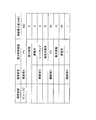
具体的には、需要家Aでは、図4に示すように、ソーラーパネル(PV)21、風力発電装置27による発電量(100kwh、5kwh)、および蓄電装置23からの電力量(5kwh)を合計して、110kwhの供給が予想されている。
具体的には、需要家Aでは、図4に示すように、ソーラーパネル(PV)21、風力発電装置27による発電量(100kwh、5kwh)、および蓄電装置23からの電力量(5kwh)を合計して、110kwhの供給が予想されている。
そして、需要家Aでは、図5に示すように、負荷24として、エアコン(100kwh)、照明(10kwh)の消費電力量を合計して110kwhの需要が予測されている。
これにより、n時間後の需要家Aにおける需給状況は、需要110kwh、供給110kwhでバランスする。
次に、需要家Bでは、図4に示すように、ヒートポンプ、電気自動車による発電量(5kwh、5kwh)を合計して、10kwhの供給が予想されている。
これにより、n時間後の需要家Aにおける需給状況は、需要110kwh、供給110kwhでバランスする。
次に、需要家Bでは、図4に示すように、ヒートポンプ、電気自動車による発電量(5kwh、5kwh)を合計して、10kwhの供給が予想されている。
そして、需要家Bでは、図5に示すように、負荷24として、TV(10kwh)の需要が予測されている。
これにより、n時間後の需要家Bにおける需給状況は、需要10kwh、供給10kwhでバランスする。
次に、需要家Cでは、図4に示すように、ソーラーパネル(PV)21、風力発電装置27による発電量(40kwh、10kwh)、および蓄電装置23からの電力量(60kwh)を合計して、110kwhの供給が予想されている。
これにより、n時間後の需要家Bにおける需給状況は、需要10kwh、供給10kwhでバランスする。
次に、需要家Cでは、図4に示すように、ソーラーパネル(PV)21、風力発電装置27による発電量(40kwh、10kwh)、および蓄電装置23からの電力量(60kwh)を合計して、110kwhの供給が予想されている。
そして、需要家Cでは、図5に示すように、負荷24として、洗濯機(10kwh)のの需要が予測されている。
これにより、n時間後の需要家Cにおける需給状況は、需要10kwh、供給110kwhで余剰電力が100kwh発生する。
次に、需要家Dでは、図4に示すように、電力供給装置を所有していないため、供給0である。
これにより、n時間後の需要家Cにおける需給状況は、需要10kwh、供給110kwhで余剰電力が100kwh発生する。
次に、需要家Dでは、図4に示すように、電力供給装置を所有していないため、供給0である。
そして、需要家Dでは、図5に示すように、負荷24として、エアコン(100kwh)の消費電力量があり、100kwhの需要が予測されている。
これにより、n時間後の需要家Dにおける需給状況は、需要100kwh、供給0kwhで、需要過多の状況となる。
ただし、需要家Dは、上述したように、需要家Cにおいて発生する余剰電力を供給してもらうことができれば、需要家A~Dを含む需要家群内における需給状況はバランスすることができる。
これにより、n時間後の需要家Dにおける需給状況は、需要100kwh、供給0kwhで、需要過多の状況となる。
ただし、需要家Dは、上述したように、需要家Cにおいて発生する余剰電力を供給してもらうことができれば、需要家A~Dを含む需要家群内における需給状況はバランスすることができる。
本実施形態の電力系統接続制御システム10では、図3~図5に示す例では、n時間後における需給バランスが取れている需要家A~Cについては、スイッチング部41,42a,43b等をOFFにするように制御することで、系統40との接続を切断することができる。
これにより、需要家A~Cでは、系統40の配電網の使用コストを削減することができる。
これにより、需要家A~Cでは、系統40の配電網の使用コストを削減することができる。
なお、需給バランスが取れている需要家A~Cのうち、需要家Cについては余剰電力100kwhが発生している。このため、制御部14は、第1スイッチング部43a~43d等を制御して、需要家Cにおいて発生する余剰電力を、需給バランスが取れていない需要家Dに融通してもよい。
この場合には、系統40の使用コストの削減は図れないものの、需要家Dから余剰電力の対価を受け取ることで、電力使用コストを削減することができる。
この場合には、系統40の使用コストの削減は図れないものの、需要家Dから余剰電力の対価を受け取ることで、電力使用コストを削減することができる。
[他の実施形態]
以上、本発明の一実施形態について説明したが、本発明は上記実施形態に限定されるものではなく、発明の要旨を逸脱しない範囲で種々の変更が可能である。
(A)
上記実施形態1では、本発明に係る電力系統接続制御方法として、図2に示すフローチャートに従って、電力系統接続制御を実施する例を挙げて説明した。しかし、本発明はこれに限定されるものではない。
例えば、図2に示すフローチャートに従って実施される電力系統接続制御方法をコンピュータに実行させる電力系統接続制御プログラムとして、本発明を実現してもよい。
また、この電力系統接続制御プログラムを格納した記録媒体として、本発明を実現してもよい。
以上、本発明の一実施形態について説明したが、本発明は上記実施形態に限定されるものではなく、発明の要旨を逸脱しない範囲で種々の変更が可能である。
(A)
上記実施形態1では、本発明に係る電力系統接続制御方法として、図2に示すフローチャートに従って、電力系統接続制御を実施する例を挙げて説明した。しかし、本発明はこれに限定されるものではない。
例えば、図2に示すフローチャートに従って実施される電力系統接続制御方法をコンピュータに実行させる電力系統接続制御プログラムとして、本発明を実現してもよい。
また、この電力系統接続制御プログラムを格納した記録媒体として、本発明を実現してもよい。
(B)
上記実施形態では、図1に示すように、電力量情報取得部11が、需要家20のEMS26から必要な情報を取得する例を挙げて説明した。しかし、本発明はこれに限定されるものではない。
上記実施形態では、図1に示すように、電力量情報取得部11が、需要家20のEMS26から必要な情報を取得する例を挙げて説明した。しかし、本発明はこれに限定されるものではない。
例えば、図6に示すように、電子端末128を用いて需要家20によって直接入力された情報を、電力量情報取得部111が取得する電力系統接続制御システム110であってもよい。
電子端末128は、需要家120が所有するPCやタブレット端末、スマートフォン、携帯電話等である。本実施形態では、電子端末128には、需要家120によって、所定時間帯ごとの電力需給予測に必要な情報が入力される。そして、電子端末128は、図6に示すように、通信回線を介して、電力系統接続制御システム110(電力量情報取得部111)と接続されている。
これにより、電力量情報取得部111は、需要家120から直接入力された情報を用いて、所定時間ごとの需要家20における電力需給の状況を予測するために必要な情報を取得することができる。
電子端末128は、需要家120が所有するPCやタブレット端末、スマートフォン、携帯電話等である。本実施形態では、電子端末128には、需要家120によって、所定時間帯ごとの電力需給予測に必要な情報が入力される。そして、電子端末128は、図6に示すように、通信回線を介して、電力系統接続制御システム110(電力量情報取得部111)と接続されている。
これにより、電力量情報取得部111は、需要家120から直接入力された情報を用いて、所定時間ごとの需要家20における電力需給の状況を予測するために必要な情報を取得することができる。
(C)
上記実施形態では、図1に示すように、需要家20が、ソーラーパネル21、蓄電装置23、風力発電装置27等の電力供給装置を所有している例を挙げて説明した。しかし、本発明はこれに限定されるものではない。
例えば、本システムにおいて需要家が所有する電力供給装置としては、上記以外に、地熱発電装置等の再生可能エネルギーを活用した発電装置、発電機、ヒートポンプ等を使用してもよい。
上記実施形態では、図1に示すように、需要家20が、ソーラーパネル21、蓄電装置23、風力発電装置27等の電力供給装置を所有している例を挙げて説明した。しかし、本発明はこれに限定されるものではない。
例えば、本システムにおいて需要家が所有する電力供給装置としては、上記以外に、地熱発電装置等の再生可能エネルギーを活用した発電装置、発電機、ヒートポンプ等を使用してもよい。
(D)
上記実施形態では、需要家20が所有する負荷24として、図5に示すように、エアコン、照明、TV,洗濯機を例として挙げて説明した。しかし、本発明はこれに限定されるものではない。
例えば、需要家が一般家庭ではなく、工場や施設等である場合には、工場や施設に設置された設備機器等を負荷としてもよい。
上記実施形態では、需要家20が所有する負荷24として、図5に示すように、エアコン、照明、TV,洗濯機を例として挙げて説明した。しかし、本発明はこれに限定されるものではない。
例えば、需要家が一般家庭ではなく、工場や施設等である場合には、工場や施設に設置された設備機器等を負荷としてもよい。
(E)
上記実施形態では、1つの需要家内において、電力の需要量が供給量以下となる場合には、系統40との接続を切断するとともに、同じ配電網を使用する需要家群に含まれる他の需要家30a~30cとの間の接続も切断する例を挙げて説明した。しかし、本発明はこれに限定されるものではない。
例えば、需要家内において、電力の需要量が供給量以下となる場合には、系統40との接続のみ切断するように、スイッチング部を切替制御してもよい。
上記実施形態では、1つの需要家内において、電力の需要量が供給量以下となる場合には、系統40との接続を切断するとともに、同じ配電網を使用する需要家群に含まれる他の需要家30a~30cとの間の接続も切断する例を挙げて説明した。しかし、本発明はこれに限定されるものではない。
例えば、需要家内において、電力の需要量が供給量以下となる場合には、系統40との接続のみ切断するように、スイッチング部を切替制御してもよい。
(F)
上記実施形態では、電力系統接続制御システム10内に、各種情報を保存する記憶部13を設けた例を挙げて説明した。しかし、本発明はこれに限定されるものではない。
上記実施形態では、電力系統接続制御システム10内に、各種情報を保存する記憶部13を設けた例を挙げて説明した。しかし、本発明はこれに限定されるものではない。
例えば、電力系統接続制御システムの外部のサーバ、クラウドサービス等を、各種情報を保存する記憶部として利用してもよい。
本発明の電力系統接続制御システムは、1つの需要家内における電力の需給状況に応じて、電力系統との接続を解除して送電網の使用コストを低減することができるという効果を奏することから、電力供給装置を所有する需要家を含むコミュニティ等において広く適用可能である。
10 電力系統接続制御システム
11 電力量情報取得部
12 電力需給予測部
13 記憶部
14 制御部
20 需要家(第1の需要家)
21 ソーラーパネル(発電装置(電力供給装置))
22 太陽光発電用電力変換装置(PCS)
22a 発電電力用電力センサ
23 蓄電装置(電力供給装置)
23a 蓄電電力用電力センサ
24 負荷
24a 負荷用電力センサ
25 分電盤
26 EMS
27 風力発電装置(発電装置(電力供給装置))
27a 風力発電用電力センサ
28 スマートメータ
30a~30c 需要家(第2の需要家)
40 系統
41 第2スイッチング部
42a~42d 第2スイッチング部
43a~43d 第1スイッチング部
110 電力系統接続制御システム
111 電力量情報取得部
120 需要家(第1の需要家)
128 電子端末
Claims (8)
- 第1の需要家が所有する電力供給装置と電力会社から電力が供給される配電網との接続切替を制御する電力系統接続制御システムであって、
前記電力供給装置における電力供給量に関する情報を取得する電力量情報取得部と、
前記電力量情報取得部において取得された情報と、前記第1の需要家における消費電力量とに基づいて、所定時間帯における電力の需給状況を予測する電力需給予測部と、
前記電力需給予測部における予測結果に基づいて、前記配電網と前記電力供給装置との接続を切り替える第1スイッチング部を制御する制御部と、
を備えている電力系統接続制御システム。 - 前記電力需給予測部は、天気予報の情報を用いて、前記電力供給装置に含まれる発電装置による所定時間帯における発電量を予測する、
請求項1に記載の電力系統接続制御システム。 - 前記電力需給予測部は、前記電力供給装置に含まれる蓄電装置の現在の蓄電量を用いて、所定時間帯における前記蓄電装置の蓄電量を予測する、
請求項1または2に記載の電力系統接続制御システム。 - 前記電力需給予測部は、前記第1の需要家の過去の生活パターンに応じた消費電力量を記録したデータに基づいて、前記第1の需要家における消費電力量を推定する、
請求項1から3のいずれか1項に記載の電力系統接続制御システム。 - 前記電力量情報取得部において取得された前記電力供給装置における電力供給量に関する情報、および前記電力需給予測部における予測結果を保存する記憶部を、さらに備えている、
請求項1から4のいずれか1項に記載の電力系統接続制御システム。 - 前記電力供給装置に関する情報は、前記第1の需要家によって入力される、
請求項1から5のいずれか1項に記載の電力系統接続制御システム。 - 第1の需要家が所有する電力供給装置と電力会社から電力が供給される配電網との接続切替を制御する電力系統接続制御方法であって、
前記電力供給装置における電力供給量に関する情報を取得する電力量情報取得ステップと、
前記電力量情報取得ステップにおいて取得された情報と、前記第1の需要家における消費電力量とに基づいて、所定時間帯における電力の需給状況を予測する電力需給予測ステップと、
前記電力需給予測ステップにおける予測結果に基づいて、前記配電網と前記電力供給装置との接続を切り替える第1スイッチング部を制御する制御ステップと、
を備えている電力系統接続制御方法。 - 第1の需要家が所有する電力供給装置と電力会社から電力が供給される配電網との接続切替を制御する電力系統接続制御プログラムであって、
前記電力供給装置における電力供給量に関する情報を取得する電力量情報取得ステップと、
前記電力量情報取得ステップにおいて取得された情報と、前記第1の需要家における消費電力量とに基づいて、所定時間帯における電力の需給状況を予測する電力需給予測ステップと、
前記電力需給予測ステップにおける予測結果に基づいて、前記配電網と前記電力供給装置との接続を切り替える第1スイッチング部を制御する制御ステップと、
を備えている電力系統接続制御方法をコンピュータに実行させる電力系統接続制御プログラム。
Applications Claiming Priority (2)
| Application Number | Priority Date | Filing Date | Title |
|---|---|---|---|
| JP2016-033946 | 2016-02-25 | ||
| JP2016033946A JP6759623B2 (ja) | 2016-02-25 | 2016-02-25 | 電力系統接続制御システム、電力系統接続制御方法および電力系統接続制御プログラム |
Publications (1)
| Publication Number | Publication Date |
|---|---|
| WO2017145459A1 true WO2017145459A1 (ja) | 2017-08-31 |
Family
ID=59685222
Family Applications (1)
| Application Number | Title | Priority Date | Filing Date |
|---|---|---|---|
| PCT/JP2016/084110 Ceased WO2017145459A1 (ja) | 2016-02-25 | 2016-11-17 | 電力系統接続制御システム、電力系統接続制御方法および電力系統接続制御プログラム |
Country Status (2)
| Country | Link |
|---|---|
| JP (1) | JP6759623B2 (ja) |
| WO (1) | WO2017145459A1 (ja) |
Cited By (1)
| Publication number | Priority date | Publication date | Assignee | Title |
|---|---|---|---|---|
| CN118804441A (zh) * | 2024-04-08 | 2024-10-18 | 江苏巧硕光电有限公司 | 一种基于节能路灯的自适应调控系统及方法 |
Families Citing this family (1)
| Publication number | Priority date | Publication date | Assignee | Title |
|---|---|---|---|---|
| JP7354657B2 (ja) * | 2019-08-01 | 2023-10-03 | 住友電気工業株式会社 | 電力制御装置、電力制御方法、およびコンピュータプログラム |
Citations (4)
| Publication number | Priority date | Publication date | Assignee | Title |
|---|---|---|---|---|
| JP2004015882A (ja) * | 2002-06-05 | 2004-01-15 | Mitsubishi Heavy Ind Ltd | 分散電源システムおよびその運用方法、並びに運用プログラム |
| JP2010220428A (ja) * | 2009-03-18 | 2010-09-30 | Toyota Motor Corp | 電力融通システム |
| JP2011015501A (ja) * | 2009-06-30 | 2011-01-20 | Panasonic Electric Works Co Ltd | 配電システム |
| JP2013186533A (ja) * | 2012-03-06 | 2013-09-19 | Yahoo Japan Corp | 情報処理方法、システム及び方法 |
-
2016
- 2016-02-25 JP JP2016033946A patent/JP6759623B2/ja active Active
- 2016-11-17 WO PCT/JP2016/084110 patent/WO2017145459A1/ja not_active Ceased
Patent Citations (4)
| Publication number | Priority date | Publication date | Assignee | Title |
|---|---|---|---|---|
| JP2004015882A (ja) * | 2002-06-05 | 2004-01-15 | Mitsubishi Heavy Ind Ltd | 分散電源システムおよびその運用方法、並びに運用プログラム |
| JP2010220428A (ja) * | 2009-03-18 | 2010-09-30 | Toyota Motor Corp | 電力融通システム |
| JP2011015501A (ja) * | 2009-06-30 | 2011-01-20 | Panasonic Electric Works Co Ltd | 配電システム |
| JP2013186533A (ja) * | 2012-03-06 | 2013-09-19 | Yahoo Japan Corp | 情報処理方法、システム及び方法 |
Cited By (1)
| Publication number | Priority date | Publication date | Assignee | Title |
|---|---|---|---|---|
| CN118804441A (zh) * | 2024-04-08 | 2024-10-18 | 江苏巧硕光电有限公司 | 一种基于节能路灯的自适应调控系统及方法 |
Also Published As
| Publication number | Publication date |
|---|---|
| JP2017153266A (ja) | 2017-08-31 |
| JP6759623B2 (ja) | 2020-09-23 |
Similar Documents
| Publication | Publication Date | Title |
|---|---|---|
| JP7113060B2 (ja) | 電力供給システムおよび電力供給方法 | |
| JP6402731B2 (ja) | 電力需給予測システム、電力需給予測方法および電力需給予測プログラム | |
| EP3422282A1 (en) | Power trading matching system, power trading matching method and power trading matching program | |
| US10461535B2 (en) | Power management system, power management method, and computer program | |
| AU2017245428B2 (en) | Power allocation system | |
| JP7513529B2 (ja) | 電力制御システムおよび電力制御方法 | |
| JP5865225B2 (ja) | 制御システム、制御装置、及び制御方法 | |
| JP2015112014A (ja) | 電力制御装置、電力制御システム及び電力制御方法 | |
| JP6786815B2 (ja) | 電力供給制御システム、電力供給制御方法および電力供給制御プログラム | |
| JP6189987B2 (ja) | 管理システム、制御装置、及び制御方法 | |
| JP6903867B2 (ja) | 電力供給経路制御システム、電力供給経路制御方法および電力供給経路制御プログラム | |
| WO2019211826A1 (en) | System and method for managing a hierarchic power distribution grid | |
| JP6328508B2 (ja) | 集合住宅節電システム | |
| US20120204044A1 (en) | Method of controlling network system | |
| US10734815B2 (en) | Power coordination control system, power coordination control method, and non-transitory storage medium | |
| JP6759623B2 (ja) | 電力系統接続制御システム、電力系統接続制御方法および電力系統接続制御プログラム | |
| JP5872353B2 (ja) | エネルギー管理システム及びエネルギー管理方法 | |
| JP6903868B2 (ja) | 電源情報推定装置、電源情報推定方法および電源情報推定プログラム | |
| JP6199640B2 (ja) | 制御装置、制御システム、分電盤及び制御方法 | |
| JP6434097B2 (ja) | 制御装置、制御システム、分電盤及び制御方法 | |
| WO2017053973A1 (en) | Apparatus for managing power of an energy device, system and method for same | |
| KR20120000010A (ko) | 네트워크 시스템 및 에너지소비부 |
Legal Events
| Date | Code | Title | Description |
|---|---|---|---|
| NENP | Non-entry into the national phase |
Ref country code: DE |
|
| 121 | Ep: the epo has been informed by wipo that ep was designated in this application |
Ref document number: 16891615 Country of ref document: EP Kind code of ref document: A1 |
|
| 122 | Ep: pct application non-entry in european phase |
Ref document number: 16891615 Country of ref document: EP Kind code of ref document: A1 |