WO2017145516A1 - Support d'enfournement pour la cuisson, et procédé de production de structure en nid d'abeille utilisant ledit support d'enfournement pour la cuisson - Google Patents
Support d'enfournement pour la cuisson, et procédé de production de structure en nid d'abeille utilisant ledit support d'enfournement pour la cuisson Download PDFInfo
- Publication number
- WO2017145516A1 WO2017145516A1 PCT/JP2016/088677 JP2016088677W WO2017145516A1 WO 2017145516 A1 WO2017145516 A1 WO 2017145516A1 JP 2016088677 W JP2016088677 W JP 2016088677W WO 2017145516 A1 WO2017145516 A1 WO 2017145516A1
- Authority
- WO
- WIPO (PCT)
- Prior art keywords
- torch
- firing
- central region
- honeycomb
- groove
- Prior art date
- Legal status (The legal status is an assumption and is not a legal conclusion. Google has not performed a legal analysis and makes no representation as to the accuracy of the status listed.)
- Ceased
Links
Images


Classifications
-
- F—MECHANICAL ENGINEERING; LIGHTING; HEATING; WEAPONS; BLASTING
- F27—FURNACES; KILNS; OVENS; RETORTS
- F27D—DETAILS OR ACCESSORIES OF FURNACES, KILNS, OVENS OR RETORTS, IN SO FAR AS THEY ARE OF KINDS OCCURRING IN MORE THAN ONE KIND OF FURNACE
- F27D5/00—Supports, screens or the like for the charge within the furnace
- F27D5/0031—Treatment baskets for ceramic articles
-
- B—PERFORMING OPERATIONS; TRANSPORTING
- B28—WORKING CEMENT, CLAY, OR STONE
- B28B—SHAPING CLAY OR OTHER CERAMIC COMPOSITIONS; SHAPING SLAG; SHAPING MIXTURES CONTAINING CEMENTITIOUS MATERIAL, e.g. PLASTER
- B28B11/00—Apparatus or processes for treating or working the shaped or preshaped articles
- B28B11/24—Apparatus or processes for treating or working the shaped or preshaped articles for curing, setting or hardening
- B28B11/243—Setting, e.g. drying, dehydrating or firing ceramic articles
-
- B—PERFORMING OPERATIONS; TRANSPORTING
- B28—WORKING CEMENT, CLAY, OR STONE
- B28B—SHAPING CLAY OR OTHER CERAMIC COMPOSITIONS; SHAPING SLAG; SHAPING MIXTURES CONTAINING CEMENTITIOUS MATERIAL, e.g. PLASTER
- B28B11/00—Apparatus or processes for treating or working the shaped or preshaped articles
- B28B11/24—Apparatus or processes for treating or working the shaped or preshaped articles for curing, setting or hardening
- B28B11/248—Supports for drying
-
- B—PERFORMING OPERATIONS; TRANSPORTING
- B28—WORKING CEMENT, CLAY, OR STONE
- B28B—SHAPING CLAY OR OTHER CERAMIC COMPOSITIONS; SHAPING SLAG; SHAPING MIXTURES CONTAINING CEMENTITIOUS MATERIAL, e.g. PLASTER
- B28B3/00—Producing shaped articles from the material by using presses; Presses specially adapted therefor
- B28B3/20—Producing shaped articles from the material by using presses; Presses specially adapted therefor wherein the material is extruded
-
- C—CHEMISTRY; METALLURGY
- C04—CEMENTS; CONCRETE; ARTIFICIAL STONE; CERAMICS; REFRACTORIES
- C04B—LIME, MAGNESIA; SLAG; CEMENTS; COMPOSITIONS THEREOF, e.g. MORTARS, CONCRETE OR LIKE BUILDING MATERIALS; ARTIFICIAL STONE; CERAMICS; REFRACTORIES; TREATMENT OF NATURAL STONE
- C04B35/00—Shaped ceramic products characterised by their composition; Ceramics compositions; Processing powders of inorganic compounds preparatory to the manufacturing of ceramic products
- C04B35/01—Shaped ceramic products characterised by their composition; Ceramics compositions; Processing powders of inorganic compounds preparatory to the manufacturing of ceramic products based on oxide ceramics
- C04B35/16—Shaped ceramic products characterised by their composition; Ceramics compositions; Processing powders of inorganic compounds preparatory to the manufacturing of ceramic products based on oxide ceramics based on silicates other than clay
- C04B35/18—Shaped ceramic products characterised by their composition; Ceramics compositions; Processing powders of inorganic compounds preparatory to the manufacturing of ceramic products based on oxide ceramics based on silicates other than clay rich in aluminium oxide
- C04B35/185—Mullite 3Al2O3-2SiO2
-
- C—CHEMISTRY; METALLURGY
- C04—CEMENTS; CONCRETE; ARTIFICIAL STONE; CERAMICS; REFRACTORIES
- C04B—LIME, MAGNESIA; SLAG; CEMENTS; COMPOSITIONS THEREOF, e.g. MORTARS, CONCRETE OR LIKE BUILDING MATERIALS; ARTIFICIAL STONE; CERAMICS; REFRACTORIES; TREATMENT OF NATURAL STONE
- C04B35/00—Shaped ceramic products characterised by their composition; Ceramics compositions; Processing powders of inorganic compounds preparatory to the manufacturing of ceramic products
- C04B35/622—Forming processes; Processing powders of inorganic compounds preparatory to the manufacturing of ceramic products
- C04B35/64—Burning or sintering processes
-
- C—CHEMISTRY; METALLURGY
- C04—CEMENTS; CONCRETE; ARTIFICIAL STONE; CERAMICS; REFRACTORIES
- C04B—LIME, MAGNESIA; SLAG; CEMENTS; COMPOSITIONS THEREOF, e.g. MORTARS, CONCRETE OR LIKE BUILDING MATERIALS; ARTIFICIAL STONE; CERAMICS; REFRACTORIES; TREATMENT OF NATURAL STONE
- C04B38/00—Porous mortars, concrete, artificial stone or ceramic ware; Preparation thereof
- C04B38/0006—Honeycomb structures
-
- B—PERFORMING OPERATIONS; TRANSPORTING
- B28—WORKING CEMENT, CLAY, OR STONE
- B28B—SHAPING CLAY OR OTHER CERAMIC COMPOSITIONS; SHAPING SLAG; SHAPING MIXTURES CONTAINING CEMENTITIOUS MATERIAL, e.g. PLASTER
- B28B3/00—Producing shaped articles from the material by using presses; Presses specially adapted therefor
- B28B3/20—Producing shaped articles from the material by using presses; Presses specially adapted therefor wherein the material is extruded
- B28B2003/203—Producing shaped articles from the material by using presses; Presses specially adapted therefor wherein the material is extruded for multi-channelled structures, e.g. honeycomb structures
-
- C—CHEMISTRY; METALLURGY
- C04—CEMENTS; CONCRETE; ARTIFICIAL STONE; CERAMICS; REFRACTORIES
- C04B—LIME, MAGNESIA; SLAG; CEMENTS; COMPOSITIONS THEREOF, e.g. MORTARS, CONCRETE OR LIKE BUILDING MATERIALS; ARTIFICIAL STONE; CERAMICS; REFRACTORIES; TREATMENT OF NATURAL STONE
- C04B2235/00—Aspects relating to ceramic starting mixtures or sintered ceramic products
- C04B2235/70—Aspects relating to sintered or melt-casted ceramic products
- C04B2235/74—Physical characteristics
- C04B2235/77—Density
-
- C—CHEMISTRY; METALLURGY
- C04—CEMENTS; CONCRETE; ARTIFICIAL STONE; CERAMICS; REFRACTORIES
- C04B—LIME, MAGNESIA; SLAG; CEMENTS; COMPOSITIONS THEREOF, e.g. MORTARS, CONCRETE OR LIKE BUILDING MATERIALS; ARTIFICIAL STONE; CERAMICS; REFRACTORIES; TREATMENT OF NATURAL STONE
- C04B2235/00—Aspects relating to ceramic starting mixtures or sintered ceramic products
- C04B2235/70—Aspects relating to sintered or melt-casted ceramic products
- C04B2235/94—Products characterised by their shape
-
- C—CHEMISTRY; METALLURGY
- C04—CEMENTS; CONCRETE; ARTIFICIAL STONE; CERAMICS; REFRACTORIES
- C04B—LIME, MAGNESIA; SLAG; CEMENTS; COMPOSITIONS THEREOF, e.g. MORTARS, CONCRETE OR LIKE BUILDING MATERIALS; ARTIFICIAL STONE; CERAMICS; REFRACTORIES; TREATMENT OF NATURAL STONE
- C04B2235/00—Aspects relating to ceramic starting mixtures or sintered ceramic products
- C04B2235/70—Aspects relating to sintered or melt-casted ceramic products
- C04B2235/95—Products characterised by their size, e.g. microceramics
-
- C—CHEMISTRY; METALLURGY
- C04—CEMENTS; CONCRETE; ARTIFICIAL STONE; CERAMICS; REFRACTORIES
- C04B—LIME, MAGNESIA; SLAG; CEMENTS; COMPOSITIONS THEREOF, e.g. MORTARS, CONCRETE OR LIKE BUILDING MATERIALS; ARTIFICIAL STONE; CERAMICS; REFRACTORIES; TREATMENT OF NATURAL STONE
- C04B2235/00—Aspects relating to ceramic starting mixtures or sintered ceramic products
- C04B2235/70—Aspects relating to sintered or melt-casted ceramic products
- C04B2235/96—Properties of ceramic products, e.g. mechanical properties such as strength, toughness, wear resistance
- C04B2235/9607—Thermal properties, e.g. thermal expansion coefficient
- C04B2235/9623—Ceramic setters properties
-
- C—CHEMISTRY; METALLURGY
- C04—CEMENTS; CONCRETE; ARTIFICIAL STONE; CERAMICS; REFRACTORIES
- C04B—LIME, MAGNESIA; SLAG; CEMENTS; COMPOSITIONS THEREOF, e.g. MORTARS, CONCRETE OR LIKE BUILDING MATERIALS; ARTIFICIAL STONE; CERAMICS; REFRACTORIES; TREATMENT OF NATURAL STONE
- C04B2235/00—Aspects relating to ceramic starting mixtures or sintered ceramic products
- C04B2235/70—Aspects relating to sintered or melt-casted ceramic products
- C04B2235/96—Properties of ceramic products, e.g. mechanical properties such as strength, toughness, wear resistance
- C04B2235/963—Surface properties, e.g. surface roughness
-
- F—MECHANICAL ENGINEERING; LIGHTING; HEATING; WEAPONS; BLASTING
- F01—MACHINES OR ENGINES IN GENERAL; ENGINE PLANTS IN GENERAL; STEAM ENGINES
- F01N—GAS-FLOW SILENCERS OR EXHAUST APPARATUS FOR MACHINES OR ENGINES IN GENERAL; GAS-FLOW SILENCERS OR EXHAUST APPARATUS FOR INTERNAL-COMBUSTION ENGINES
- F01N3/00—Exhaust or silencing apparatus having means for purifying, rendering innocuous, or otherwise treating exhaust
- F01N3/08—Exhaust or silencing apparatus having means for purifying, rendering innocuous, or otherwise treating exhaust for rendering innocuous
- F01N3/10—Exhaust or silencing apparatus having means for purifying, rendering innocuous, or otherwise treating exhaust for rendering innocuous by thermal or catalytic conversion of noxious components of exhaust
- F01N3/24—Exhaust or silencing apparatus having means for purifying, rendering innocuous, or otherwise treating exhaust for rendering innocuous by thermal or catalytic conversion of noxious components of exhaust characterised by constructional aspects of converting apparatus
- F01N3/28—Construction of catalytic reactors
- F01N3/2803—Construction of catalytic reactors characterised by structure, by material or by manufacturing of catalyst support
- F01N3/2825—Ceramics
- F01N3/2828—Ceramic multi-channel monoliths, e.g. honeycombs
Definitions
- the present invention relates to a firing torch and a method for manufacturing a honeycomb structure using the firing torch. More specifically, in order to fire an unfired honeycomb formed body in a firing furnace, a firing torch laid under the honeycomb formed body, and a method for manufacturing a honeycomb structure using the firing torch (hereinafter, It is simply referred to as “honeycomb structure manufacturing method”).
- a ceramic honeycomb structure (hereinafter simply referred to as a “honeycomb structure”) is prepared by preparing a molding material (kneaded material) and extruding it into a desired honeycomb shape using an extrusion molding machine. After finishing cutting, it is manufactured through a firing step of firing at a high temperature.
- the honeycomb formed body is placed on a shelf board with one molded body end face facing downward, and is put into the firing furnace together with the shelf board. Is done.
- a “tochi” for firing is used between the shelf board and the honeycomb molded body. In this way, the honeycomb molded body and the shelf board are prevented from coming into direct contact with each other.
- a torch for example, a torch called a “press torch” obtained by press-molding a ceramic material and firing it may be used.
- the torch including “press torch” will be generically defined as “firing torch”.
- a material from extrusion molding to before firing is referred to as “honeycomb molded body”, and a material fired through the firing process is referred to as “honeycomb structure”.
- the shelf When firing the honeycomb formed body using the firing torch, the shelf after placing the fired honeycomb structures after placing the fired honeycomb structures on the shelf board in an aligned state.
- recovers the torch for baking on a board is needed.
- the firing torch is stored in a storage case in a state where it is stacked in multiple stages up and down, and is carried to the vicinity of the shelf board.
- the work time is increased due to manual work, which may cause a problem in the accuracy of the position, for example, the manufacturing efficiency is lowered and the position when the firing torch is aligned is shifted. For this reason, attempts have been made to automate the work related to the placement of the firing torch, etc. for the purpose of reducing the work burden on the worker, improving the production efficiency by shortening the work time, and improving the work accuracy. .
- a robot arm that can reproduce a pre-programmed motion using an existing robot control device.
- mounting and alignment on the shelf board and further recovery from the shelf board are performed by clamping the torch outer periphery of the firing torch from the side by opening and closing the pair of clamping parts of the robot arm. Is possible.
- a certain amount of space is required around the firing torch (stack).
- the firing torch is stored in the storage case in a stacked state in which a plurality of firing torch is stacked in multiple stages, and another stack is disposed around one stack. Are stored densely.
- the suction conveyance device 101 that conveys and places the firing torch 100 using suction force is used (see FIG. 10).
- the suction conveyance device 101 is provided with a suction cup-shaped suction part 102 formed of rubber or the like at the tip of the arm, and the suction part 102 is brought into close contact with the torch upper surface part 103 of the firing torch 100, The air inside the suction unit 102 is sucked and the pressure is reduced. Thereby, the space inside the suction part 102 becomes lower than the atmospheric pressure, and the firing torch 100 and the suction part 102 are in close contact with each other.
- the firing torch 100 is lifted in conjunction with the movement of the suction unit 102.
- the firing torch 100 can be transported to an arbitrary position.
- the suction by the suction unit 102 is stopped and the suction state is released. That is, the air inside the suction unit 102 is returned to atmospheric pressure.
- the adhesion between the firing torch 100 and the suction portion 102 is eliminated, and the firing torch 100 can be placed on a shelf board or the like.
- the suction part 102 and the arm only move in the vertical direction. Therefore, unlike the above-described clamping by the robot arm, there is no need for a wide space around the stacked body 104, and there is no problem that the use conditions are limited.
- the firing torch 100 conveyed in this case is formed of a porous material obtained by press-molding a ceramic material and then firing. Therefore, when the suction part 102 is brought into close contact with the firing torch 100a located at the uppermost stage of the stack 104 as shown in FIG. 10 and the firing torch 100a is to be lifted, the firing torch 100b located at the lower stage thereof. May also be sucked and lifted together (see the central stack in FIG. 10).
- adjusting the suction force of the suction conveyance device 101 to establish an optimum condition for sucking the firing torch 100a step by step is also considered.
- the suction force is too weak, the uppermost firing torch 100a cannot be reliably lifted, and problems such as the firing torch 100a coming off from the suction portion 102 during transportation may occur.
- the suction force is too strong, as described above, the multi-stage firing tochis 100a and 100b are transported together, and the transport failure may not be resolved.
- the present invention has been made in view of the above situation, and in the automation of operations such as conveyance and placement of the firing torch using the suction conveyance device, the firing torch capable of suppressing the occurrence of conveyance failure, It is another object of the present invention to provide a method for manufacturing a honeycomb structure.
- a torch for firing and a method for manufacturing a honeycomb structure that solve the above-mentioned problems.
- a plate-like firing torch that is used to fire a honeycomb formed body and is interposed between the honeycomb formed body and a shelf board, the torch lower surface portion of the firing torch facing the shelf board Is provided with a central region portion formed in a region including the center of the lower surface of the torch lower surface portion, and a peripheral region portion formed in a region around the central region portion, the peripheral region portion being the central region portion
- a torch for firing having at least four torch groove portions having a concave section extending radially from the center of the lower surface along a direction from the boundary to the outer periphery of the torch.
- the torch groove portions adjacent to each other are arranged in the peripheral region portion at the same radiation angle from the center of the lower surface, and extend linearly from the boundary toward the outer periphery of the torch.
- the torch for firing as described.
- the firing torch is configured to have an elliptical shape
- the central region portion is configured to have an elliptical shape similar to the firing torch
- a short axis of the central region portion is 10 mm to 35 mm.
- the torch upper surface portion on which the honeycomb formed body is placed is opposed to the torch lower surface portion, the flat portion is in contact with at least part of the end surface of the honeycomb formed body, and the flat surface from the torch outer peripheral portion.
- a torch for firing in which at least four or more cross-sectionally shaped torch grooves extending radially from the center of the lower surface are respectively arranged along the direction from the boundary with the central region toward the outer periphery of the torch.
- a suction conveyance device is used, and the suction conveyance is performed on the top surface of the firing torch located at the uppermost stage of the stack in which a plurality of firing torch are stacked in multiple stages.
- the firing torch of the present invention it is possible to suppress the occurrence of conveyance failure when the firing torch is transported using suction force. Furthermore, according to the method for manufacturing a honeycomb structure of the present invention, it is possible to form the honeycomb structure by firing the honeycomb formed body while suppressing the occurrence of defective conveyance of the firing torch in the firing step. In particular, the operation of installing the firing torch on the shelf board using the suction conveyance device can be performed stably and efficiently.
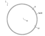
- a firing torch 1 is interposed between a honeycomb formed body 20 to be fired and a shelf board 21, and is made of a porous material made of a ceramic material. This is a substantially disk-shaped member.
- the firing torch 1 is used in the firing step of the honeycomb structure manufacturing method in which the honeycomb formed body 20 is fired at a predetermined firing temperature to form a honeycomb structure (not shown).
- the firing torch 1 is a surface facing the shelf plate 21, is located on the lower side of the torch lower surface portion 2, and is opposed to the torch lower surface portion 2, and the molded body end surface of the honeycomb molded body 20. 22, at least part of which is in contact with the top surface 3 of the torch 1 positioned above the firing torch 1, and the ends 2 a and 3 a of the bottom surface 2 and the top surface 3 of the torch 1. And a torch outer peripheral portion 4 located on the side surface side of the.
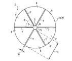
- the circular torch lower surface portion 2 When the firing torch 1 is viewed from the bottom surface side (corresponding to the lower side in the drawing in FIG. 2), the circular torch lower surface portion 2 has a central region portion 5 formed in a region including the lower surface center C, and a central region portion 5. And a surrounding region portion 6 formed by a region surrounding the periphery of the substrate. Furthermore, in the surrounding area part 6, radially from the lower surface center C along the direction from the boundary B (see the broken line circle in FIG. 3) between the central area part 5 and the surrounding area part 6 to the torch outer peripheral part 4, In addition, six torch groove portions 7 extending linearly are provided.
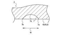
- the torch groove portion 7 is a groove having a substantially semicircular cross section (concave cross section) with respect to the flat region surface 6a of the surrounding region portion 6 (torch lower surface portion 2). Is formed.
- the space between the one end 7 a and the other end 7 b between the torch groove portion 7 having a substantially semicircular cross section and the region surface 6 a corresponds to the groove width W of the torch groove portion 7.
- the shape of the torch groove portion 7 is not limited to the substantially semicircular shape in cross section, and may be other shapes such as a polygonal shape or an elliptical shape.
- the angle between the adjacent torch groove portions 7 (radiation angle ⁇ : see FIG. 3) is set to 60 °. That is, with the lower surface center C as the starting point, a plurality of torch groove portions 7 are arranged at equal intervals.
- the central region portion 5 provided on the torch lower surface portion 2 has a circular shape in the case of the firing torch 1 of the present embodiment.
- the diameter of the central region portion 5 is 10 mm. It is set in the range of ⁇ 35 mm. That is, the lower limit and the upper limit of the area (area) of the central region 5 are set.
- the diameter of the central region portion 5 is smaller than 10 mm, the center side ends 7c of the plurality of torch groove portions 7 are concentrated on the lower surface center C. In order to avoid such a state, it is specified that the diameter is at least 10 mm or more.
- the diameter of the central region portion 5 exceeds 35 mm, the ratio indicated by the central region portion 5 in the torch lower surface portion 2 is increased. As a result, the effect (details will be described later) of the present invention obtained by the torch groove portion 7 of the surrounding region portion 6 cannot be sufficiently expected. Therefore, the range of the diameter of the central region portion 5 is defined as described above.
- the central region portion may also be configured to exhibit an elliptical shape similar to the shape of the firing torch.
- at least the elliptical minor axis is set to be 10 mm or more in order to avoid concentrating on the center side ends 7c of the plurality of torch grooves.
- the firing torch may have an elliptical shape, or the central region does not necessarily have an elliptical shape, and may have a circular shape.
- the central region portion need not be limited to a circular shape or an elliptical shape, and may be other polygonal shapes.
- the groove width W of the torch groove portion 7 is in the range of 0.5 mm to 2.0 mm.
- the height from the region surface 6a of the peripheral region portion 6 to the deepest portion 7d of the torch groove portion 7 is 1 ⁇ 2 or less of the groove width W.
- the groove width W is smaller than 0.5 mm, when the stacking body 8 is stacked in multiple stages, there is a gap between the firing position 1a at the upper position and the firing position 1b at the lower position.
- the upper and lower firing torch 1a and 1b are in close contact with each other, and there is a high possibility that they will be in an adsorbed state.
- a groove width W of at least 0.5 mm or more is required. Further, if the groove width W is up to 2.0 mm, a sufficient gap is formed between the upper and lower firing torch 1a, 1b, and therefore no further expansion of the groove width W is required. . Therefore, the groove width W of the torch groove portion 7 is defined within the range of 0.5 mm to 2.0 mm.
- the firing torch 1 of the present embodiment is set so that the ratio (groove area ratio) of the groove area of the torch groove part 7 shown in the entire area of the torch lower surface part 2 is at least 1.0% or more.
- the total area of the torch lower surface 2 is the area of the central region 5, the area of the peripheral region 6 other than the torch groove 7, and the area of the portion opened to the outside of the torch groove 7 (groove area). ).
- the groove area in the case of the firing torch 1 of the present embodiment is the area of a rectangular region obtained by multiplying the groove width W by the groove length L of the torch groove portion 7 extending from the boundary B to the torch outer peripheral portion 4. Further, it is calculated by multiplying 6 which is the number of the torch groove portions 7 (see FIGS. 3 and 5).
- the groove area ratio is calculated based on the obtained groove area and the total area of the torch lower surface 2. Thereby, the groove area ratio can be easily obtained.
- the groove area ratio may be calculated by other methods.
- image analysis processing may be performed on a captured image obtained by capturing the torch lower surface portion 2, and the torch groove region and other regions may be discriminated to obtain the groove area ratio.
- the torch upper surface portion 3 of the firing torch 1 of the present embodiment is opposed to the torch lower surface portion 2 and is used to place the honeycomb molded body 20, and at least a part of the molded body end surface 22 of the honeycomb molded body 20.
- the torch lower surface portion 2 is formed in a flat shape so as to be in contact with the shelf board 21, and a part thereof is formed in a semicircular cross section.
- the torch upper surface portion 3 ascends upward as a whole, and only the vicinity of the center is formed by the flat portion 11.
- the central region 5 of the torch lower surface portion 2 and the flat portion 11 of the torch upper surface portion 3 have the same area or the flat portion 11 with respect to the central region portion 5. May be formed with a large area.
- the flat portion 11 is not limited to a circular shape, and may be any shape that can stably place the honeycomb formed body 20.
- the torch upper surface portion 3 includes the flat portion 11, the placement of the honeycomb formed body 20 is stable, and furthermore, only a part of the end surface 22 of the formed body is in contact with the torch upper surface portion 3. The possibility of restraining is reduced. As a result, when firing is performed using the firing torch 1 of the present embodiment, product quality can be stabilized without causing cell deformation, partition wall breakage, or the like in the fired honeycomb structure (not shown). .
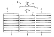
- a stack 8 in which a plurality of firing torch 1 are stacked in multiple stages is constructed (see FIG. 7).
- the torch lower surface portion 2 particularly, the central region portion 5
- the flat portion 11 formed by a plane parallel to the torch lower surface portion 2 are provided, the upper and lower firing tochis when stacked in multiple stages are provided. 1 does not become unstable. Therefore, the stacked body 8 can be stored in a storage case or the like in a stable state.
- the firing torch 1 of the present embodiment includes a plurality of torch groove portions 7 in the peripheral region portion 6 of the torch lower surface portion 2.
- the stacked body 8 see FIG. 7 in which a plurality of firing tochis 1 are stacked in multiple stages
- the suction conveyance device 9 using the suction conveyance device 9, the torch upper surface portion 3 of the firing torch 1a positioned at the uppermost stage of the stacked body 8 is used.
- the suction section 10 is brought into close contact with the pressure reducing state and only one firing torch 1 is transported, the firing torch 1a located at the uppermost stage and the firing torch 1b located at the lower stage are brought into close contact with each other. There is no (suction conveyance process).
- the groove area ratio of the groove area of the torch groove portion 7 to the total area of the torch lower surface portion 2 is set to at least 1.0% or more in order to ensure a sufficient air flow path.
- the groove area ratio of the torch groove portion 7 is lower than 1.0%, the air flow path is not sufficient, and the two firing torch 1a and 1b are in close contact with each other and become in an adsorbed state by the suction portion 10. May be lifted. Therefore, the groove area ratio is defined within the above range.
- the firing torch 1 of the present embodiment is formed from a ceramic material.
- the material is not particularly limited, and for example, various materials conventionally used as a base material for a firing torch can be used. For example, it is possible to use a material that is converted into mullite, cordierite, silicon carbide, alumina, or the like by firing at a high temperature.
- the method for forming the firing torch 1 is not particularly limited.
- the torch upper surface portion 3 is ground so as to have a flat portion 11 and a raised portion 12, and a plurality of torch groove portions 7 are ground on the torch lower surface portion 2, respectively. It can also be provided by processing.
- the firing torch used in the firing process is a large amount, and performing the above-described cutting process for each of them may lead to complication of the production process of the firing torch and an increase in production cost.
- a press working mold formed in accordance with the shape of the firing torch is used, a ceramic material as a raw material is filled in the mold, and a desired press pressure is applied to form. It doesn't matter.
- a torch for firing can be produced by firing the torch molded body that has been punched from the mold. Thereby, ceramic prestoches can be mass-produced and used as a firing torch of the present invention.
- the firing torch and the manufacturing method of the honeycomb structure of the present invention will be described based on the following examples.
- the firing torch and the manufacturing method of the honeycomb structure of the present invention are described in these examples. It is not limited.
- the firing torch is a press-molded porous press torch, which is fired at a firing temperature of 1400 to 1500 ° C.
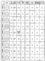
- Example 3 Firing Tochi of Examples and Comparative Examples
- the number of grooves in Example 3 is six, the radiation angle ⁇ is 60 °, the center diameter is 25 mm, and the groove width is 2 mm.
- Example 1 has four grooves and a radiation angle ⁇ of 90 °
- Example 2 has five grooves and a radiation angle ⁇ of 72 °
- Example 4 has a groove number.
- Example 5 and Example 8 are both elliptical, and Example 5 has a central region having an elliptical shape with a minor axis of 25 mm.
- Example 8 has a central diameter of 25 mm. This is a circular shape.
- Example 6 is based on the firing torch of Example 3, and the diameter (center diameter) of the central region is changed to 10 mm, and Example 7 is changed to the center diameter of 35 mm.
- the groove width W is 0.5 mm.
- the torch for firing of Comparative Example 1 is one in which one torch groove portion having a groove width W of 2 mm is arranged in the diameter direction
- Comparative Example 2 is one in which a similar pair of torch groove portions are arranged in parallel.
- four torch groove portions are arranged in a lattice pattern. That is, it deviates from the conditions of the torch for firing of the present invention in which the torch groove portions are arranged radially.
- the groove width W of the torch groove is 0.3 mm
- Comparative Example 6 the groove width W of the torch groove is 5 mm.
- FIGS. 8 and 9 A summary of detailed specifications such as the shape of the torch for firing in Examples 1 to 9 and Comparative Examples 1 to 5 is shown in FIGS. 8 and 9, respectively.
- a firing step for firing the honeycomb formed body which is one step in the method for manufacturing a honeycomb structure, was actually performed using the firing torch, and a change in the shape of the firing torch was confirmed.
- the honeycomb formed body to be fired was obtained by extruding (molding process) a molding material (kneaded material) prepared at a predetermined blending ratio using a known extruder.
- the honeycomb molded body placing step of placing the honeycomb molded body with the molded body end face facing downward is included.
- a firing torch is interposed between the honeycomb formed body and the shelf board.
- the honeycomb formed body is put into the firing furnace, and firing is performed.
- the manufacturing of the honeycomb structure is completed (the manufacturing method of the honeycomb structure of the present invention).
- the firing process under the same conditions is repeatedly performed on one firing torch, and the firing torch warpage after 10 firings is 0.5 mm or less “A”, 6 to 9 times.
- the case where the occurrence of warping of the firing torch after firing was 0.5 mm or less was evaluated as “B”, and the case where the occurrence of warping of the firing torch after 0.6 firing was 0.6 mm or more was evaluated as “C”.
- FIG. 8 and FIG. 9 show the evaluation results for the evaluation criteria (4) to (6).
- the number of grooves in the torch groove portion in FIG. 9 is one (Comparative Example 1), two (Comparative Example 2), or a torch for firing formed in a lattice shape (Comparative Example 3).
- the change in shape was evaluated as “C”, indicating that it was not suitable for repeated firing. That is, as defined in the firing torch of the present invention, it was confirmed that at least four or more torch groove portions were required on the bottom surface portion of the torch and it was necessary to arrange them radially. Further, in the case of Comparative Example 1 and Comparative Example 2, the product quality of the honeycomb structure after firing is also affected.
- the groove width W of the torch groove portion is as narrow as 0.3 mm and the groove area ratio is 0.8% (Comparative Example 5), the air path is not sufficiently formed. “Adsorption” occurred, resulting in a “C” rating.
- the groove width W of the torch groove portion was 0.5 mm and the groove area ratio was 1.3% (Example 9), the above adsorption was not confirmed at all and the evaluation was “A”. That is, it was indicated that the torch groove portion should be formed with a groove width W of 0.5 mm or more and a groove area ratio of 1.0% or more.
- the groove width W was 5 mm (Comparative Example 6), although no adsorption occurred, the product quality of the honeycomb structure deteriorated and the evaluation was “C”. Therefore, the groove width W needs to be in an appropriate range.
- the firing tochi of Examples 1 to 9 obtained an evaluation of “B” or more at a minimum in any of the evaluation criteria.
- the number of grooves is five or more, and from Example 7, it was confirmed that the center diameter is more preferably a value smaller than 35 mm.
- the shape of the torch for firing was not limited to a circular shape, and it was confirmed that an equivalent effect was exhibited even if it was an elliptical shape (Examples 5 and 8).
- the honeycomb structure can be manufactured under stable conditions by using the firing torch of the present invention.
- the firing torch of the present invention can be particularly usefully used in a firing step which is one step of a method for producing a honeycomb structure for producing a ceramic honeycomb structure used as a catalyst carrier for automobile exhaust gas purification. . Furthermore, the honeycomb structure can be stably manufactured from the honeycomb formed body by the method for manufacturing a honeycomb structure using the firing torch.
Landscapes
- Engineering & Computer Science (AREA)
- Chemical & Material Sciences (AREA)
- Ceramic Engineering (AREA)
- Structural Engineering (AREA)
- Mechanical Engineering (AREA)
- Manufacturing & Machinery (AREA)
- Materials Engineering (AREA)
- Organic Chemistry (AREA)
- General Engineering & Computer Science (AREA)
- Inorganic Chemistry (AREA)
- Furnace Charging Or Discharging (AREA)
- Chemical Kinetics & Catalysis (AREA)
- Porous Artificial Stone Or Porous Ceramic Products (AREA)
- Filtering Materials (AREA)
- Health & Medical Sciences (AREA)
- Toxicology (AREA)
- Combustion & Propulsion (AREA)
Abstract
La présente invention concerne un support d'enfournement 1 pour la cuisson qui comprend : une section 2 de surface inférieure de support d'enfournement en regard d'une tablette ; une section 5 de région centrale formée par une région comprenant un centre C de surface inférieure de la section 2 de surface inférieure du support d'enfournement ; et une section 6 de région périphérique formée par une région entourant la section de région centrale 5. Ladite section 6 de région périphérique comprend au moins quatre sections 7 de rainures de support d'enfournement, chacune ayant une forme évidée dans une section transversale et s'étendant radialement, depuis le centre C de la surface inférieure, dans une direction allant de la limite B avec la section 5 de région centrale vers la section circonférentielle externe 4 du support d'enfournement.
Priority Applications (4)
| Application Number | Priority Date | Filing Date | Title |
|---|---|---|---|
| DE112016006475.6T DE112016006475B4 (de) | 2016-02-23 | 2016-12-26 | Brenneinsatz und Verfahren zur Herstellung einer Wabenstruktur unter Verwendung des Brenneinsatzes |
| JP2018501017A JP6735334B2 (ja) | 2016-02-23 | 2016-12-26 | 焼成用トチ、及び焼成用トチを用いたハニカム構造体の製造方法 |
| CN201680080115.3A CN108698941B (zh) | 2016-02-23 | 2016-12-26 | 烧成用垫板、以及使用了烧成用垫板的蜂窝结构体的制造方法 |
| US16/043,412 US10969175B2 (en) | 2016-02-23 | 2018-07-24 | Setter for firing, and method for producing honeycomb structure using setter for firing |
Applications Claiming Priority (2)
| Application Number | Priority Date | Filing Date | Title |
|---|---|---|---|
| JP2016032447 | 2016-02-23 | ||
| JP2016-032447 | 2016-02-23 |
Related Child Applications (1)
| Application Number | Title | Priority Date | Filing Date |
|---|---|---|---|
| US16/043,412 Continuation US10969175B2 (en) | 2016-02-23 | 2018-07-24 | Setter for firing, and method for producing honeycomb structure using setter for firing |
Publications (1)
| Publication Number | Publication Date |
|---|---|
| WO2017145516A1 true WO2017145516A1 (fr) | 2017-08-31 |
Family
ID=59686234
Family Applications (1)
| Application Number | Title | Priority Date | Filing Date |
|---|---|---|---|
| PCT/JP2016/088677 Ceased WO2017145516A1 (fr) | 2016-02-23 | 2016-12-26 | Support d'enfournement pour la cuisson, et procédé de production de structure en nid d'abeille utilisant ledit support d'enfournement pour la cuisson |
Country Status (5)
| Country | Link |
|---|---|
| US (1) | US10969175B2 (fr) |
| JP (1) | JP6735334B2 (fr) |
| CN (1) | CN108698941B (fr) |
| DE (1) | DE112016006475B4 (fr) |
| WO (1) | WO2017145516A1 (fr) |
Cited By (2)
| Publication number | Priority date | Publication date | Assignee | Title |
|---|---|---|---|---|
| US20220009840A1 (en) * | 2018-11-30 | 2022-01-13 | Corning Incorporated | Honeycomb body manufacturing methods |
| DE112016006475B4 (de) * | 2016-02-23 | 2024-03-21 | Ngk Insulators, Ltd. | Brenneinsatz und Verfahren zur Herstellung einer Wabenstruktur unter Verwendung des Brenneinsatzes |
Citations (4)
| Publication number | Priority date | Publication date | Assignee | Title |
|---|---|---|---|---|
| JPS62202870A (ja) * | 1986-02-20 | 1987-09-07 | 日本碍子株式会社 | セラミツクスハニカム構造体の焼成方法 |
| JPH06211568A (ja) * | 1993-01-18 | 1994-08-02 | Ngk Insulators Ltd | ベータアルミナ管の焼成方法 |
| JPH0715738U (ja) * | 1993-08-31 | 1995-03-17 | 三菱マテリアル株式会社 | 焼結用治具 |
| JP2005219977A (ja) * | 2004-02-06 | 2005-08-18 | Ngk Insulators Ltd | セラミックスハニカム焼成用トチ及びセラミックスハニカムの焼成方法 |
Family Cites Families (13)
| Publication number | Priority date | Publication date | Assignee | Title |
|---|---|---|---|---|
| US2246448A (en) * | 1937-02-18 | 1941-06-17 | Jr Frank H Mahan | Setter |
| US4174950A (en) | 1977-12-19 | 1979-11-20 | United Technologies Corporation | Ceramic base and cap useful in firing ceramic shell molds |
| DE8321679U1 (de) * | 1983-07-27 | 1983-12-01 | Norton Co., 01606 Worcester, Mass. | Platte aus feuerfestem material |
| US4786542A (en) | 1986-02-20 | 1988-11-22 | Ngk Insulators, Ltd. | Setters and firing of ceramic honeycomb structural bodies by using the same |
| JP4205902B2 (ja) * | 2001-09-20 | 2009-01-07 | イソライト工業株式会社 | セラミックセッター及びその製造方法 |
| JP4882202B2 (ja) | 2004-02-09 | 2012-02-22 | 東ソー株式会社 | 高シリカモルデナイトの合成方法 |
| JP4633734B2 (ja) * | 2004-09-27 | 2011-02-16 | 日本碍子株式会社 | 焼成用敷板及びこれを用いたハニカム成形体の焼成方法 |
| CN105115304B (zh) * | 2008-03-05 | 2018-03-20 | 日本碍子株式会社 | 陶瓷烧成用窑工具板 |
| JP5779794B2 (ja) * | 2013-03-19 | 2015-09-16 | 日本碍子株式会社 | ベースセッター |
| US10479734B2 (en) * | 2013-08-15 | 2019-11-19 | Corning Incorporated | Method and apparatus for thermally debindering a cellular ceramic green body |
| CN204160488U (zh) * | 2014-10-14 | 2015-02-18 | 昆山龙腾光电有限公司 | 真空吸盘及具有其的机械手臂 |
| JP6735334B2 (ja) * | 2016-02-23 | 2020-08-05 | 日本碍子株式会社 | 焼成用トチ、及び焼成用トチを用いたハニカム構造体の製造方法 |
| JP6397843B2 (ja) * | 2016-03-24 | 2018-09-26 | 日本碍子株式会社 | ハニカム構造体の製造方法 |
-
2016
- 2016-12-26 JP JP2018501017A patent/JP6735334B2/ja active Active
- 2016-12-26 WO PCT/JP2016/088677 patent/WO2017145516A1/fr not_active Ceased
- 2016-12-26 CN CN201680080115.3A patent/CN108698941B/zh active Active
- 2016-12-26 DE DE112016006475.6T patent/DE112016006475B4/de active Active
-
2018
- 2018-07-24 US US16/043,412 patent/US10969175B2/en active Active
Patent Citations (4)
| Publication number | Priority date | Publication date | Assignee | Title |
|---|---|---|---|---|
| JPS62202870A (ja) * | 1986-02-20 | 1987-09-07 | 日本碍子株式会社 | セラミツクスハニカム構造体の焼成方法 |
| JPH06211568A (ja) * | 1993-01-18 | 1994-08-02 | Ngk Insulators Ltd | ベータアルミナ管の焼成方法 |
| JPH0715738U (ja) * | 1993-08-31 | 1995-03-17 | 三菱マテリアル株式会社 | 焼結用治具 |
| JP2005219977A (ja) * | 2004-02-06 | 2005-08-18 | Ngk Insulators Ltd | セラミックスハニカム焼成用トチ及びセラミックスハニカムの焼成方法 |
Cited By (3)
| Publication number | Priority date | Publication date | Assignee | Title |
|---|---|---|---|---|
| DE112016006475B4 (de) * | 2016-02-23 | 2024-03-21 | Ngk Insulators, Ltd. | Brenneinsatz und Verfahren zur Herstellung einer Wabenstruktur unter Verwendung des Brenneinsatzes |
| US20220009840A1 (en) * | 2018-11-30 | 2022-01-13 | Corning Incorporated | Honeycomb body manufacturing methods |
| US12065384B2 (en) * | 2018-11-30 | 2024-08-20 | Corning Incorporated | Honeycomb body manufacturing methods |
Also Published As
| Publication number | Publication date |
|---|---|
| JPWO2017145516A1 (ja) | 2019-01-10 |
| CN108698941B (zh) | 2021-06-25 |
| US10969175B2 (en) | 2021-04-06 |
| US20180328667A1 (en) | 2018-11-15 |
| CN108698941A (zh) | 2018-10-23 |
| JP6735334B2 (ja) | 2020-08-05 |
| DE112016006475B4 (de) | 2024-03-21 |
| DE112016006475T5 (de) | 2018-11-08 |
Similar Documents
| Publication | Publication Date | Title |
|---|---|---|
| JP6200404B2 (ja) | ハニカム成形体焼成用生トチ、及びハニカム成形体の焼成方法 | |
| JP6224637B2 (ja) | ハニカム構造体の製造方法、及びハニカム成形体 | |
| WO2015008503A1 (fr) | Accessoire de cuisson | |
| WO2017145516A1 (fr) | Support d'enfournement pour la cuisson, et procédé de production de structure en nid d'abeille utilisant ledit support d'enfournement pour la cuisson | |
| CN107226701A (zh) | 蜂窝结构体的制造方法 | |
| JP6224643B2 (ja) | 棚板割れ検知方法、ハニカム構造体の搬送方法、棚板割れ検知装置、及び棚板搬送装置 | |
| US7971864B2 (en) | Positioning method and device for columnar structure | |
| JP2012158507A (ja) | 電子部品焼成用セッター | |
| JP6378155B2 (ja) | 熱処理用棚 | |
| JP6403096B2 (ja) | セラミックハニカム構造体の製造方法 | |
| JP6312617B2 (ja) | ハニカム構造体の製造方法 | |
| CN114603140B (zh) | 一种多孔金属薄膜的烧结装置及方法 | |
| JPH10238964A (ja) | 窯炉用棚板及び窯炉用支柱一体型棚板 | |
| CN219103708U (zh) | 板状烧制夹具 | |
| JPH04227471A (ja) | 支持部材 | |
| WO2017163497A1 (fr) | Plaque de cuisson et procédé de fabrication d'une structure en nid d'abeilles utilisant la plaque de cuisson | |
| JP4509541B2 (ja) | セラミックス板の製造方法、及びセラミックス板 | |
| JPH10227579A (ja) | 窯炉棚板用支柱 | |
| KR20240171835A (ko) | 원자력 현미경 검사장비용 sic 검사 홀더 | |
| JP2007245522A (ja) | セラミック円柱状体用把持装置 | |
| JP4501528B2 (ja) | セラミック成形体の焼成方法 | |
| JP2015524349A (ja) | セラミック・フィルタの配列を結合するプロセス | |
| JPH0715738U (ja) | 焼結用治具 | |
| JPH0715737U (ja) | 焼結用治具 |
Legal Events
| Date | Code | Title | Description |
|---|---|---|---|
| WWE | Wipo information: entry into national phase |
Ref document number: 2018501017 Country of ref document: JP |
|
| WWE | Wipo information: entry into national phase |
Ref document number: 112016006475 Country of ref document: DE |
|
| 121 | Ep: the epo has been informed by wipo that ep was designated in this application |
Ref document number: 16891671 Country of ref document: EP Kind code of ref document: A1 |
|
| 122 | Ep: pct application non-entry in european phase |
Ref document number: 16891671 Country of ref document: EP Kind code of ref document: A1 |