WO2017145648A1 - 焼結含油軸受及びその製造方法 - Google Patents
焼結含油軸受及びその製造方法 Download PDFInfo
- Publication number
- WO2017145648A1 WO2017145648A1 PCT/JP2017/003072 JP2017003072W WO2017145648A1 WO 2017145648 A1 WO2017145648 A1 WO 2017145648A1 JP 2017003072 W JP2017003072 W JP 2017003072W WO 2017145648 A1 WO2017145648 A1 WO 2017145648A1
- Authority
- WO
- WIPO (PCT)
- Prior art keywords
- powder
- copper
- oil
- impregnated bearing
- sintered
- Prior art date
- Legal status (The legal status is an assumption and is not a legal conclusion. Google has not performed a legal analysis and makes no representation as to the accuracy of the status listed.)
- Ceased
Links
Images


Classifications
-
- F—MECHANICAL ENGINEERING; LIGHTING; HEATING; WEAPONS; BLASTING
- F16—ENGINEERING ELEMENTS AND UNITS; GENERAL MEASURES FOR PRODUCING AND MAINTAINING EFFECTIVE FUNCTIONING OF MACHINES OR INSTALLATIONS; THERMAL INSULATION IN GENERAL
- F16C—SHAFTS; FLEXIBLE SHAFTS; ELEMENTS OR CRANKSHAFT MECHANISMS; ROTARY BODIES OTHER THAN GEARING ELEMENTS; BEARINGS
- F16C33/00—Parts of bearings; Special methods for making bearings or parts thereof
- F16C33/02—Parts of sliding-contact bearings
- F16C33/04—Brasses; Bushes; Linings
- F16C33/06—Sliding surface mainly made of metal
- F16C33/12—Structural composition; Use of special materials or surface treatments, e.g. for rust-proofing
- F16C33/121—Use of special materials
-
- B—PERFORMING OPERATIONS; TRANSPORTING
- B22—CASTING; POWDER METALLURGY
- B22F—WORKING METALLIC POWDER; MANUFACTURE OF ARTICLES FROM METALLIC POWDER; MAKING METALLIC POWDER; APPARATUS OR DEVICES SPECIALLY ADAPTED FOR METALLIC POWDER
- B22F1/00—Metallic powder; Treatment of metallic powder, e.g. to facilitate working or to improve properties
-
- B—PERFORMING OPERATIONS; TRANSPORTING
- B22—CASTING; POWDER METALLURGY
- B22F—WORKING METALLIC POWDER; MANUFACTURE OF ARTICLES FROM METALLIC POWDER; MAKING METALLIC POWDER; APPARATUS OR DEVICES SPECIALLY ADAPTED FOR METALLIC POWDER
- B22F3/00—Manufacture of workpieces or articles from metallic powder characterised by the manner of compacting or sintering; Apparatus specially adapted therefor ; Presses and furnaces
- B22F3/12—Both compacting and sintering
- B22F3/16—Both compacting and sintering in successive or repeated steps
-
- B—PERFORMING OPERATIONS; TRANSPORTING
- B22—CASTING; POWDER METALLURGY
- B22F—WORKING METALLIC POWDER; MANUFACTURE OF ARTICLES FROM METALLIC POWDER; MAKING METALLIC POWDER; APPARATUS OR DEVICES SPECIALLY ADAPTED FOR METALLIC POWDER
- B22F3/00—Manufacture of workpieces or articles from metallic powder characterised by the manner of compacting or sintering; Apparatus specially adapted therefor ; Presses and furnaces
- B22F3/24—After-treatment of workpieces or articles
-
- B—PERFORMING OPERATIONS; TRANSPORTING
- B22—CASTING; POWDER METALLURGY
- B22F—WORKING METALLIC POWDER; MANUFACTURE OF ARTICLES FROM METALLIC POWDER; MAKING METALLIC POWDER; APPARATUS OR DEVICES SPECIALLY ADAPTED FOR METALLIC POWDER
- B22F5/00—Manufacture of workpieces or articles from metallic powder characterised by the special shape of the product
- B22F5/10—Manufacture of workpieces or articles from metallic powder characterised by the special shape of the product of articles with cavities or holes, not otherwise provided for in the preceding subgroups
- B22F5/106—Tube or ring forms
-
- C—CHEMISTRY; METALLURGY
- C22—METALLURGY; FERROUS OR NON-FERROUS ALLOYS; TREATMENT OF ALLOYS OR NON-FERROUS METALS
- C22C—ALLOYS
- C22C1/00—Making non-ferrous alloys
- C22C1/04—Making non-ferrous alloys by powder metallurgy
- C22C1/0425—Copper-based alloys
-
- C—CHEMISTRY; METALLURGY
- C22—METALLURGY; FERROUS OR NON-FERROUS ALLOYS; TREATMENT OF ALLOYS OR NON-FERROUS METALS
- C22C—ALLOYS
- C22C38/00—Ferrous alloys, e.g. steel alloys
-
- C—CHEMISTRY; METALLURGY
- C22—METALLURGY; FERROUS OR NON-FERROUS ALLOYS; TREATMENT OF ALLOYS OR NON-FERROUS METALS
- C22C—ALLOYS
- C22C38/00—Ferrous alloys, e.g. steel alloys
- C22C38/16—Ferrous alloys, e.g. steel alloys containing copper
-
- C—CHEMISTRY; METALLURGY
- C22—METALLURGY; FERROUS OR NON-FERROUS ALLOYS; TREATMENT OF ALLOYS OR NON-FERROUS METALS
- C22C—ALLOYS
- C22C9/00—Alloys based on copper
-
- F—MECHANICAL ENGINEERING; LIGHTING; HEATING; WEAPONS; BLASTING
- F16—ENGINEERING ELEMENTS AND UNITS; GENERAL MEASURES FOR PRODUCING AND MAINTAINING EFFECTIVE FUNCTIONING OF MACHINES OR INSTALLATIONS; THERMAL INSULATION IN GENERAL
- F16C—SHAFTS; FLEXIBLE SHAFTS; ELEMENTS OR CRANKSHAFT MECHANISMS; ROTARY BODIES OTHER THAN GEARING ELEMENTS; BEARINGS
- F16C17/00—Sliding-contact bearings for exclusively rotary movement
- F16C17/10—Sliding-contact bearings for exclusively rotary movement for both radial and axial load
-
- F—MECHANICAL ENGINEERING; LIGHTING; HEATING; WEAPONS; BLASTING
- F16—ENGINEERING ELEMENTS AND UNITS; GENERAL MEASURES FOR PRODUCING AND MAINTAINING EFFECTIVE FUNCTIONING OF MACHINES OR INSTALLATIONS; THERMAL INSULATION IN GENERAL
- F16C—SHAFTS; FLEXIBLE SHAFTS; ELEMENTS OR CRANKSHAFT MECHANISMS; ROTARY BODIES OTHER THAN GEARING ELEMENTS; BEARINGS
- F16C33/00—Parts of bearings; Special methods for making bearings or parts thereof
- F16C33/02—Parts of sliding-contact bearings
- F16C33/04—Brasses; Bushes; Linings
- F16C33/06—Sliding surface mainly made of metal
- F16C33/10—Construction relative to lubrication
- F16C33/1025—Construction relative to lubrication with liquid, e.g. oil, as lubricant
- F16C33/103—Construction relative to lubrication with liquid, e.g. oil, as lubricant retained in or near the bearing
- F16C33/104—Construction relative to lubrication with liquid, e.g. oil, as lubricant retained in or near the bearing in a porous body, e.g. oil impregnated sintered sleeve
-
- F—MECHANICAL ENGINEERING; LIGHTING; HEATING; WEAPONS; BLASTING
- F16—ENGINEERING ELEMENTS AND UNITS; GENERAL MEASURES FOR PRODUCING AND MAINTAINING EFFECTIVE FUNCTIONING OF MACHINES OR INSTALLATIONS; THERMAL INSULATION IN GENERAL
- F16C—SHAFTS; FLEXIBLE SHAFTS; ELEMENTS OR CRANKSHAFT MECHANISMS; ROTARY BODIES OTHER THAN GEARING ELEMENTS; BEARINGS
- F16C33/00—Parts of bearings; Special methods for making bearings or parts thereof
- F16C33/02—Parts of sliding-contact bearings
- F16C33/04—Brasses; Bushes; Linings
- F16C33/06—Sliding surface mainly made of metal
- F16C33/12—Structural composition; Use of special materials or surface treatments, e.g. for rust-proofing
- F16C33/128—Porous bearings, e.g. bushes of sintered alloy
-
- F—MECHANICAL ENGINEERING; LIGHTING; HEATING; WEAPONS; BLASTING
- F16—ENGINEERING ELEMENTS AND UNITS; GENERAL MEASURES FOR PRODUCING AND MAINTAINING EFFECTIVE FUNCTIONING OF MACHINES OR INSTALLATIONS; THERMAL INSULATION IN GENERAL
- F16C—SHAFTS; FLEXIBLE SHAFTS; ELEMENTS OR CRANKSHAFT MECHANISMS; ROTARY BODIES OTHER THAN GEARING ELEMENTS; BEARINGS
- F16C33/00—Parts of bearings; Special methods for making bearings or parts thereof
- F16C33/02—Parts of sliding-contact bearings
- F16C33/04—Brasses; Bushes; Linings
- F16C33/06—Sliding surface mainly made of metal
- F16C33/14—Special methods of manufacture; Running-in
- F16C33/145—Special methods of manufacture; Running-in of sintered porous bearings
-
- G—PHYSICS
- G11—INFORMATION STORAGE
- G11B—INFORMATION STORAGE BASED ON RELATIVE MOVEMENT BETWEEN RECORD CARRIER AND TRANSDUCER
- G11B19/00—Driving, starting, stopping record carriers not specifically of filamentary or web form, or of supports therefor; Control thereof; Control of operating function ; Driving both disc and head
- G11B19/20—Driving; Starting; Stopping; Control thereof
- G11B19/2009—Turntables, hubs and motors for disk drives; Mounting of motors in the drive
- G11B19/2036—Motors characterized by fluid-dynamic bearings
-
- H—ELECTRICITY
- H02—GENERATION; CONVERSION OR DISTRIBUTION OF ELECTRIC POWER
- H02K—DYNAMO-ELECTRIC MACHINES
- H02K21/00—Synchronous motors having permanent magnets; Synchronous generators having permanent magnets
- H02K21/12—Synchronous motors having permanent magnets; Synchronous generators having permanent magnets with stationary armatures and rotating magnets
- H02K21/22—Synchronous motors having permanent magnets; Synchronous generators having permanent magnets with stationary armatures and rotating magnets with magnets rotating around the armatures, e.g. flywheel magnetos
-
- H—ELECTRICITY
- H02—GENERATION; CONVERSION OR DISTRIBUTION OF ELECTRIC POWER
- H02K—DYNAMO-ELECTRIC MACHINES
- H02K5/00—Casings; Enclosures; Supports
- H02K5/04—Casings or enclosures characterised by the shape, form or construction thereof
- H02K5/16—Means for supporting bearings, e.g. insulating supports or means for fitting bearings in the bearing-shields
- H02K5/167—Means for supporting bearings, e.g. insulating supports or means for fitting bearings in the bearing-shields using sliding-contact or spherical cap bearings
- H02K5/1677—Means for supporting bearings, e.g. insulating supports or means for fitting bearings in the bearing-shields using sliding-contact or spherical cap bearings radially supporting the rotor around a fixed spindle; radially supporting the rotor directly
-
- H—ELECTRICITY
- H02—GENERATION; CONVERSION OR DISTRIBUTION OF ELECTRIC POWER
- H02K—DYNAMO-ELECTRIC MACHINES
- H02K7/00—Arrangements for handling mechanical energy structurally associated with dynamo-electric machines, e.g. structural association with mechanical driving motors or auxiliary dynamo-electric machines
- H02K7/08—Structural association with bearings
- H02K7/086—Structural association with bearings radially supporting the rotor around a fixed spindle; radially supporting the rotor directly
-
- B—PERFORMING OPERATIONS; TRANSPORTING
- B22—CASTING; POWDER METALLURGY
- B22F—WORKING METALLIC POWDER; MANUFACTURE OF ARTICLES FROM METALLIC POWDER; MAKING METALLIC POWDER; APPARATUS OR DEVICES SPECIALLY ADAPTED FOR METALLIC POWDER
- B22F2301/00—Metallic composition of the powder or its coating
- B22F2301/10—Copper
-
- B—PERFORMING OPERATIONS; TRANSPORTING
- B22—CASTING; POWDER METALLURGY
- B22F—WORKING METALLIC POWDER; MANUFACTURE OF ARTICLES FROM METALLIC POWDER; MAKING METALLIC POWDER; APPARATUS OR DEVICES SPECIALLY ADAPTED FOR METALLIC POWDER
- B22F2301/00—Metallic composition of the powder or its coating
- B22F2301/35—Iron
-
- B—PERFORMING OPERATIONS; TRANSPORTING
- B22—CASTING; POWDER METALLURGY
- B22F—WORKING METALLIC POWDER; MANUFACTURE OF ARTICLES FROM METALLIC POWDER; MAKING METALLIC POWDER; APPARATUS OR DEVICES SPECIALLY ADAPTED FOR METALLIC POWDER
- B22F2304/00—Physical aspects of the powder
- B22F2304/10—Micron size particles, i.e. above 1 micrometer up to 500 micrometer
-
- F—MECHANICAL ENGINEERING; LIGHTING; HEATING; WEAPONS; BLASTING
- F16—ENGINEERING ELEMENTS AND UNITS; GENERAL MEASURES FOR PRODUCING AND MAINTAINING EFFECTIVE FUNCTIONING OF MACHINES OR INSTALLATIONS; THERMAL INSULATION IN GENERAL
- F16C—SHAFTS; FLEXIBLE SHAFTS; ELEMENTS OR CRANKSHAFT MECHANISMS; ROTARY BODIES OTHER THAN GEARING ELEMENTS; BEARINGS
- F16C17/00—Sliding-contact bearings for exclusively rotary movement
- F16C17/10—Sliding-contact bearings for exclusively rotary movement for both radial and axial load
- F16C17/102—Sliding-contact bearings for exclusively rotary movement for both radial and axial load with grooves in the bearing surface to generate hydrodynamic pressure
- F16C17/107—Sliding-contact bearings for exclusively rotary movement for both radial and axial load with grooves in the bearing surface to generate hydrodynamic pressure with at least one surface for radial load and at least one surface for axial load
-
- F—MECHANICAL ENGINEERING; LIGHTING; HEATING; WEAPONS; BLASTING
- F16—ENGINEERING ELEMENTS AND UNITS; GENERAL MEASURES FOR PRODUCING AND MAINTAINING EFFECTIVE FUNCTIONING OF MACHINES OR INSTALLATIONS; THERMAL INSULATION IN GENERAL
- F16C—SHAFTS; FLEXIBLE SHAFTS; ELEMENTS OR CRANKSHAFT MECHANISMS; ROTARY BODIES OTHER THAN GEARING ELEMENTS; BEARINGS
- F16C2204/00—Metallic materials; Alloys
- F16C2204/10—Alloys based on copper
-
- F—MECHANICAL ENGINEERING; LIGHTING; HEATING; WEAPONS; BLASTING
- F16—ENGINEERING ELEMENTS AND UNITS; GENERAL MEASURES FOR PRODUCING AND MAINTAINING EFFECTIVE FUNCTIONING OF MACHINES OR INSTALLATIONS; THERMAL INSULATION IN GENERAL
- F16C—SHAFTS; FLEXIBLE SHAFTS; ELEMENTS OR CRANKSHAFT MECHANISMS; ROTARY BODIES OTHER THAN GEARING ELEMENTS; BEARINGS
- F16C2204/00—Metallic materials; Alloys
- F16C2204/60—Ferrous alloys, e.g. steel alloys
-
- F—MECHANICAL ENGINEERING; LIGHTING; HEATING; WEAPONS; BLASTING
- F16—ENGINEERING ELEMENTS AND UNITS; GENERAL MEASURES FOR PRODUCING AND MAINTAINING EFFECTIVE FUNCTIONING OF MACHINES OR INSTALLATIONS; THERMAL INSULATION IN GENERAL
- F16C—SHAFTS; FLEXIBLE SHAFTS; ELEMENTS OR CRANKSHAFT MECHANISMS; ROTARY BODIES OTHER THAN GEARING ELEMENTS; BEARINGS
- F16C2220/00—Shaping
- F16C2220/20—Shaping by sintering pulverised material, e.g. powder metallurgy
-
- F—MECHANICAL ENGINEERING; LIGHTING; HEATING; WEAPONS; BLASTING
- F16—ENGINEERING ELEMENTS AND UNITS; GENERAL MEASURES FOR PRODUCING AND MAINTAINING EFFECTIVE FUNCTIONING OF MACHINES OR INSTALLATIONS; THERMAL INSULATION IN GENERAL
- F16C—SHAFTS; FLEXIBLE SHAFTS; ELEMENTS OR CRANKSHAFT MECHANISMS; ROTARY BODIES OTHER THAN GEARING ELEMENTS; BEARINGS
- F16C2223/00—Surface treatments; Hardening; Coating
- F16C2223/02—Mechanical treatment, e.g. finishing
- F16C2223/04—Mechanical treatment, e.g. finishing by sizing, by shaping to final size by small plastic deformation, e.g. by calibrating or coining
-
- F—MECHANICAL ENGINEERING; LIGHTING; HEATING; WEAPONS; BLASTING
- F16—ENGINEERING ELEMENTS AND UNITS; GENERAL MEASURES FOR PRODUCING AND MAINTAINING EFFECTIVE FUNCTIONING OF MACHINES OR INSTALLATIONS; THERMAL INSULATION IN GENERAL
- F16C—SHAFTS; FLEXIBLE SHAFTS; ELEMENTS OR CRANKSHAFT MECHANISMS; ROTARY BODIES OTHER THAN GEARING ELEMENTS; BEARINGS
- F16C2240/00—Specified values or numerical ranges of parameters; Relations between them
- F16C2240/40—Linear dimensions, e.g. length, radius, thickness, gap
- F16C2240/48—Particle sizes
-
- F—MECHANICAL ENGINEERING; LIGHTING; HEATING; WEAPONS; BLASTING
- F16—ENGINEERING ELEMENTS AND UNITS; GENERAL MEASURES FOR PRODUCING AND MAINTAINING EFFECTIVE FUNCTIONING OF MACHINES OR INSTALLATIONS; THERMAL INSULATION IN GENERAL
- F16C—SHAFTS; FLEXIBLE SHAFTS; ELEMENTS OR CRANKSHAFT MECHANISMS; ROTARY BODIES OTHER THAN GEARING ELEMENTS; BEARINGS
- F16C2370/00—Apparatus relating to physics, e.g. instruments
- F16C2370/12—Hard disk drives or the like
-
- H—ELECTRICITY
- H02—GENERATION; CONVERSION OR DISTRIBUTION OF ELECTRIC POWER
- H02K—DYNAMO-ELECTRIC MACHINES
- H02K2205/00—Specific aspects not provided for in the other groups of this subclass relating to casings, enclosures, supports
- H02K2205/03—Machines characterised by thrust bearings
Definitions
- the present invention relates to a sintered oil-impregnated bearing, and particularly to a sintered oil-impregnated bearing incorporated in a fluid dynamic pressure bearing device.
- the fluid dynamic pressure bearing device includes a lubricating oil filled in a radial bearing gap between the outer peripheral surface of the shaft member and the inner peripheral surface of the bearing member by relative rotation between the bearing member and the shaft member inserted in the inner periphery thereof.
- the shaft member is supported in a non-contact manner so as to be relatively rotatable with this pressure (dynamic pressure action).
- the fluid dynamic bearing device is suitably used for a spindle motor of an HDD disk drive device or the like because of its excellent rotational accuracy and quietness.
- a sintered oil-impregnated bearing in which oil is impregnated in internal pores of a sintered body is sometimes used.
- the sintered oil-impregnated bearing has countless minute openings on the surface, when the pressure of the lubricating oil filled in the radial bearing gap increases, the inner diameter of the sintered oil-impregnated bearing increases from the inner periphery. Lubricating oil may enter the pores, and the lubricating oil pressure (oil film strength) in the radial bearing gap may be reduced. Such a phenomenon is called “dynamic pressure loss” and is a problem to be avoided in a fluid dynamic pressure bearing device using a sintered oil-impregnated bearing.
- Rotational sizing is a processing method in which sizing pins having a substantially polygonal cross section are press-fitted into the inner peripheral surface of the sintered body and rotated to crush the surface openings on the inner peripheral surface.
- the rollability of the surface layer of the sintered body by rotational sizing is increased by increasing the content of copper that is relatively soft and easy to be rolled. be able to.
- a sintered body was produced using raw material powder having a high copper powder ratio (for example, 50% by mass or more), and rotational sizing was applied to the inner peripheral surface (bearing surface). Even in this case, rough air holes may remain on the bearing surface, and it cannot be said that the decrease in oil film strength due to the loss of dynamic pressure can be reliably prevented.
- An object of the present invention is to prevent the formation of rough air holes on the bearing surface of a sintered oil-impregnated bearing, and to reliably prevent a decrease in oil film strength due to dynamic pressure loss.
- the present invention provides a sintered oil-impregnated bearing having a copper-iron-based sintered body containing 40 mass% or more of copper, the sintered body having a particle size on the surface of the iron powder.
- a sintered oil-impregnated bearing comprising a copper structure derived from a copper powder of a partial diffusion alloy powder in which copper powder of 20 ⁇ m or less is diffusion-bonded in advance and a copper structure derived from a single copper powder.
- the above sintered oil-impregnated bearing comprises a step of preparing a raw material powder by mixing a partial diffusion alloy powder in which a copper powder having a particle size of 20 ⁇ m or less is diffusion bonded to the surface of iron powder and a single copper powder; A step of obtaining a green compact by compression molding, a step of obtaining a sintered body by sintering the green compact, and rolling the surface layer material of the inner peripheral surface of the sintered body to the inner peripheral surface It can be manufactured through a step of performing a sealing treatment and a step of impregnating the internal pores of the sintered body with oil.
- a sintered oil-impregnated bearing is formed using a partial diffusion alloy powder in which fine copper powder (specifically, copper powder having a particle size of 20 ⁇ m or less) is diffusion bonded to the surface of iron powder.
- fine copper powder specifically, copper powder having a particle size of 20 ⁇ m or less
- Partially diffused alloy powder is manufactured by heating in a state where iron powder and copper powder are mixed. At this time, it is easy to adhere in a state where fine copper powder enters a recess of iron powder having a distorted shape. For this reason, the distorted shape of the partially diffused alloy powder as a whole is relaxed, and the formation of rough air holes due to the distorted iron powder is suppressed.
- the raw powder contains distorted iron powder
- the fine single copper powder will enter the recesses of the distorted iron powder. It is also considered that the formation of rough air holes can be prevented.
- the raw material powder contains a large amount of copper (40% by mass or more)
- the raw material powder contains a large amount of fine single-piece copper powder, which reduces the fluidity of the raw material powder, Compression molding (forming) may be difficult.
- the partial diffusion alloy powder as described above, since the fine copper powder is pre-adhered to the iron powder in a state of adhering to the iron powder, without reducing the fluidity of the raw material powder, There is no adverse effect on compression molding.
- the ratio of the copper powder in the partial diffusion alloy powder is usually about 15 to 30% by mass. Become. For this reason, in order to raise the ratio of the copper in a sintered compact to 40 mass% or more, it is preferable to mix
- the single copper powder it is preferable to use electrolytic copper powder.
- electrolytic copper powder since each particle has a dendritic shape, the powder is easily entangled when compression-molded. Sintering in this state facilitates the progress of the sintering, so that the strength of the sintered body is improved and the internal pores of the sintered body can be refined.
- a dynamic pressure generating portion (for example, a dynamic pressure groove) that positively generates a dynamic pressure action on the lubricating oil filled in the bearing gap may be formed on the inner peripheral surface or end surface of the sintered body.
- the pressure of the lubricating oil in the bearing gap is further increased, it is particularly effective to prevent the formation of rough atmospheric holes and prevent the dynamic pressure from being lost as described above.
- a fluid dynamic pressure bearing device including a radial bearing portion that supports a shaft member in a radial direction in a non-contact manner has an excellent rotation accuracy because the oil film strength is high.
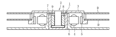
- FIG. 1 shows a spindle motor used in an HDD disk drive device.
- the spindle motor includes a fluid dynamic pressure bearing device 1, a disk hub 3 fixed to the shaft member 2 of the fluid dynamic pressure bearing device 1, a stator coil 4 and a rotor magnet 5 that are opposed to each other via a radial gap, A bracket 6 is provided.
- the stator coil 4 is fixed to the bracket 6, and the rotor magnet 5 is fixed to the disk hub 3.
- a housing 7 of the fluid dynamic bearing device 1 is fixed to the inner peripheral surface of the bracket 6.
- the disc hub 3 holds a predetermined number (two in the illustrated example) of discs D.
- the stator coil 4 When the stator coil 4 is energized, the rotor magnet 5 rotates, and accordingly, the disk D held on the disk hub 3 rotates integrally with the shaft member 2.
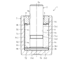
- the fluid dynamic bearing device 1 includes a sintered oil-impregnated bearing 8 according to an embodiment of the present invention, a shaft member 2 inserted into the inner periphery of the sintered oil-impregnated bearing 8, and an inner peripheral surface. And a bottomed cylindrical housing 7 to which the sintered oil-impregnated bearing 8 is fixed, and a seal member 9 disposed in the opening of the housing 7.
- the opening side of the housing 7 in the axial direction is referred to as the upper side, and the opposite side is referred to as the lower side.
- the shaft member 2 is formed of a metal material such as stainless steel, for example, and includes a shaft portion 2a and a flange portion 2b provided at the lower end of the shaft portion 2a.
- the outer peripheral surface 2a1 of the shaft portion 2a has a cylindrical surface shape, and a relief portion 2a2 having a smaller diameter than other regions is formed in the axially intermediate portion.
- the outer diameter of the shaft portion 2a is, for example, about 0.5 to 4 mm.
- the sintered oil-impregnated bearing 8 is made of a copper-iron-based sintered body containing copper and iron as main components.
- the sintered oil-impregnated bearing 8 has a cylindrical shape, and a radial bearing surface is formed on the inner peripheral surface 8a thereof.
- radial bearing surfaces are formed at two locations spaced apart in the axial direction of the inner peripheral surface 8 a of the sintered oil-impregnated bearing 8, and each of the radial bearing surfaces serves as a dynamic pressure generating portion.
- Dynamic pressure grooves 8a1 and 8a2 arranged in a ring bone shape are provided.
- a region indicated by cross-hatching in the figure indicates a hill that rises to the inner diameter side.
- the upper dynamic pressure groove 8a1 has an asymmetric shape in the axial direction
- the lower dynamic pressure groove 8a2 has a symmetrical shape in the axial direction.
- the lubricating oil in the radial bearing gap is pushed in the axial direction by the upper dynamic pressure groove 8 a 1 having an axially asymmetric shape, whereby the lubricating oil is forcibly circulated inside the housing 7.
- both the upper and lower dynamic pressure grooves 8a1 and 8a2 may have an axially symmetrical shape.
- the upper and lower dynamic pressure grooves 8a1 and 8a2 may be continuous in the axial direction, or one or both of the upper and lower dynamic pressure grooves 8a1 and 8a2 may be omitted.
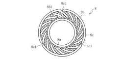
- a thrust bearing surface is formed on the lower end surface 8b of the sintered oil-impregnated bearing 8, and a spiral-shaped dynamic pressure groove 8b1 as shown in FIG. 4 is formed as a dynamic pressure generating portion on the thrust bearing surface.
- the illustrated dynamic pressure groove 8b1 is a pump-in type that pushes lubricating oil into the inner diameter side as the shaft member 2 rotates.
- an annular groove 8d1 and a plurality of radial grooves 8d2 provided on the inner diameter side of the annular groove 8d1 are formed on the upper end surface 8d of the sintered oil-impregnated bearing 8.
- a plurality of axial grooves 8 c 1 are provided on the outer peripheral surface 8 c of the sintered oil-impregnated bearing 8 at equal intervals in the circumferential direction.
- the space on the outer diameter side of the flange portion 2b of the shaft member 2 communicates with the seal space S through the axial groove 8c1, the annular groove 8d1, the radial groove 8d2, and the like. Occurrence is prevented.
- the housing 7 has a cylindrical side portion 7a and a disc-shaped bottom portion 7b that closes an opening below the side portion 7a (see FIG. 2).
- the housing 7 is formed of resin or metal, and in the illustrated example, the side portion 7a and the bottom portion 7b are integrally molded with resin.
- a pump-in type spiral-shaped dynamic pressure groove is formed as a thrust dynamic pressure generating portion (not shown). This dynamic pressure groove can be formed simultaneously with the injection molding of the housing 7, for example.
- the side part 7a and the bottom part 7b of the housing 7 may be formed separately.
- the seal member 9 is formed in an annular shape with resin or metal, and is fixed to the upper end portion of the inner peripheral surface 7a1 of the side portion 7a of the housing 7 (see FIG. 2).
- the lower end surface 9 b of the seal member 9 is in contact with the upper end surface 8 d of the sintered oil-impregnated bearing 8.
- the inner peripheral surface 9a of the seal member 9 has a tapered shape that is gradually reduced in diameter downward.
- the inner peripheral surface 9a of the seal member 9 faces the outer peripheral surface 2a1 of the shaft portion 2a in the radial direction, and a wedge-shaped seal space S in which the radial dimension is gradually reduced downward is formed therebetween.
- the seal space S functions as a capillary force seal and prevents leakage of the lubricating oil filled in the housing 7 to the outside.
- Lubricating oil is injected into the fluid dynamic bearing device 1 composed of the above components.
- the internal space of the fluid dynamic pressure bearing device 1 including the internal pores of the sintered oil-impregnated bearing 8 is filled with the lubricating oil, and the oil level is always maintained within the range of the seal space S.
- a radial bearing gap is formed between the inner peripheral surface 8a of the sintered oil-impregnated bearing 8 and the outer peripheral surface 2a1 of the shaft portion 2a. Then, the pressure of the oil film in the radial bearing gap is increased by the dynamic pressure grooves 8a1 and 8a2 formed on the inner peripheral surface 8a of the sintered oil-impregnated bearing 8, and the shaft member 2 is rotatably supported in a non-contact manner by this dynamic pressure action.
- the first radial bearing portion R1 and the second radial bearing portion R2 are configured.
- the sintered oil-impregnated bearing 8 is mainly subjected to (A) raw material powder mixing step, (B) molding step, (C) sintering step, (D) sealing treatment step, and (E) dynamic pressure groove forming step in order. Manufactured. Hereinafter, each step will be described in detail.
- the raw material powder of the sintered oil-impregnated bearing 8 is prepared by mixing a plurality of types of powders described later.
- the raw material powder used in the present embodiment is composed of a partial diffusion alloy powder, a simple copper powder, and a low melting point metal powder.
- Various molding lubricants for example, a lubricant for improving releasability
- solid lubricants for example, graphite powder
- each of the above powders will be described in detail.
- Part diffusion alloy powder Fe—Cu partial diffusion alloy powder in which copper powder 13 is diffusion bonded to the surface of iron powder 12 is used.
- Fe—Cu portions in which a large number of copper powders 13 having an average particle size smaller than that of the iron powder 12 are diffusion bonded to the surface of the iron powder 12.
- Diffusion alloy powder is used.
- copper diffuses into iron to form an Fe—Cu alloy.
- the partial diffusion alloy powder 11 is formed by heating a mixed powder of iron powder 12 and copper powder 13 to diffuse and bond them, and then pulverizing them.
- a fine copper powder 13 is easily fitted into the recess 12a of the iron powder 12 having a distorted shape as shown in FIG. 5b, and both are diffusion-bonded in this state. Thereby, the recessed part 12a of the iron powder 12 is filled with the fine copper powder 13, and the distorted shape is solved to some extent.
- the particle size of the partial diffusion alloy powder 11 is too large, rough air holes may be formed between the particles of the partial diffusion alloy powder 11. For this reason, it is preferable to use the partially diffused alloy powder 11 having a particle size of 106 ⁇ m or less. Further, from the viewpoint of ensuring the fluidity of the raw material powder, it is desirable to use the partial diffusion alloy powder 11 that does not contain 25% by mass or more of particles having a particle size of 45 ⁇ m or less.
- the iron powder 12 constituting the partial diffusion alloy powder 11 known iron powders such as reduced iron powder and atomized iron powder can be used, but reduced iron powder is used in this embodiment.
- the reduced iron powder has an irregular shape that approximates a spherical shape and has a sponge shape (porous shape) having internal pores, and is also referred to as sponge iron powder.
- the iron powder 12 used preferably has a particle size of 20 ⁇ m to 106 ⁇ m, and more preferably a particle size of 38 ⁇ m to 75 ⁇ m.
- the copper powder 13 constituting the partial diffusion alloy powder 11 a widely used irregular shape or dendritic copper powder can be widely used.
- electrolytic copper powder, atomized copper powder, or the like is used.
- an atomized copper powder having a large number of irregularities on the surface, an irregular shape that approximates a spherical shape as a whole particle, and excellent in formability is used.
- the electrolytic copper powder is excellent in sinterability, if the electrolytic copper powder is used, the bond with the iron powder 12 can be further enhanced.
- the copper powder 13 to be used has a smaller particle diameter than the iron powder 12, and specifically has a particle diameter of 20 ⁇ m or less.
- the copper powder 13 in order to ensure the adhesion amount to the iron powder 12, it is desirable for the copper powder 13 to have a certain size, for example, a particle diameter of 5 ⁇ m or more is used.
- the proportion of Cu in the partial diffusion alloy powder 11 is 10 to 30% by mass (preferably 22 to 26% by mass).
- Both the electrolytic copper powder and the atomized copper powder can be used as the single copper powder, but it is particularly preferable to use the electrolytic copper powder. This is because, in the electrolytic copper powder, each particle has a dendritic shape, so that the particles are easily entangled and the internal pores can be refined.
- the single copper powder preferably has a particle size of 63 ⁇ m or less, and more preferably 45 ⁇ m or less. This is because the pores formed between the particles are further refined. Further, from the viewpoint of ensuring the fluidity of the raw material powder, it is desirable to use a single copper powder that does not contain particles having a particle size of 20 ⁇ m or less in an amount of 60% by mass or more.
- Low melting point metal powder a metal powder having a melting point of 700 ° C. or less, for example, a powder containing tin, zinc, phosphorus or the like is used.
- tin powder particularly atomized tin powder, which can easily diffuse into copper and iron and can be used as a single powder, is used.
- tin powder those having a particle size of 63 ⁇ m or less are preferably used, and those containing 90% by mass or more of particles having a particle size of 45 ⁇ m or less are more preferably used.
- each powder described above is mixed at a predetermined ratio. If the proportion of copper in the raw material powder is too small, the proportion of copper on the bearing surface of the sintered oil-impregnated bearing 8 will be insufficient, and the rollability of the surface layer during the sealing treatment described later may be insufficient. Accordingly, the copper contained in the raw material powder (the total of the copper powder of the partial diffusion alloy powder and the single copper powder) is 40% by mass or more (preferably 50% by mass or more). On the other hand, from the viewpoint of cost, the proportion of copper in the raw material powder is 75% by mass or less (preferably 65% by mass or less).
- the blending ratio of iron (iron powder of the partial diffusion alloy powder) in the raw material powder is 25% by mass or more (preferably 38% by mass or more) and 50% by mass or less (preferably 42% by mass or less).
- the blending ratio of the partial diffusion alloy powder is set so that the ratio of the iron powder 12 to the whole raw material powder is 25 to 50% by mass.
- the blending ratio of the simple copper powder is set to 35 to 60% by mass.
- the amount of the low melting point metal powder is too small, the progress of the liquid phase sintering becomes insufficient, resulting in a decrease in strength. If the amount is too large, there is a problem that the number of coarse air holes increases. %.
- the particle size of the powder is determined by irradiating a particle group with laser light and calculating the particle size distribution by calculating from the intensity distribution pattern of the diffracted and scattered light emitted from the particle group.
- PITA-3 manufactured by Seishin Co., Ltd.
- particle size of X ⁇ m or less in the present specification means that particles having a particle size exceeding X ⁇ m are substantially not included (not including 3% by mass or more), for example, passing through a sieve having an opening of X ⁇ m. Means a possible powder.
- particle size of Y ⁇ m or more means that the particle size is substantially free of particles having a particle size of less than Y ⁇ m (not containing 3% by mass or more). It means the powder remaining on the sieve.
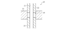
- (B) Molding step In the molding step, the shape approximated to the sintered oil-impregnated bearing 8 shown in Fig. 3 is obtained by compressing the raw material powder 10 using a molding die 20 as shown in Figs. 6a and 6b.
- the green compact 18 (substantially finished product shape) is obtained.
- the molding die 20 has a core 21, upper and lower punches 22 and 23, and a die 24 that are coaxially arranged as main components.
- the molding die 20 is set in a die set of a cam type molding press, for example.
- the raw material powder 10 is filled into a cavity defined by the core 21, the lower punch 23, and the die 24 (see FIG. 6a). Thereafter, the upper punch 22 is lowered and the raw powder 10 is compressed to form the green compact 18 (see FIG. 6b). And the upper punch 22 and the lower punch 23 are raised, and the green compact 18 is extracted out of the cavity.
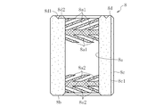
- the structure of the green compact 18 thus formed is shown in FIG.
- the iron powder 12 and the copper powder 13, the single-piece copper powder 14, and the tin powder 15 constituting the partial diffusion alloy powder 11 are uniformly dispersed.
- the partial diffusion alloy powder 11 used in the present embodiment includes iron powder 12 having a distorted shape
- fine copper powder 13 has entered and joined into the recess 12a of the iron powder 12 in advance.
- the distorted shape is solved to some extent (see FIG. 6b). Therefore, it is possible to suppress the formation of rough atmospheric holes due to the distorted iron powder 12.
- the fine copper powder 13 having a particle diameter of 20 ⁇ m or less is mixed with the raw material powder in a state of being joined to the iron powder 12, the fine copper powder 13 reduces the fluidity of the raw material powder, It does not segregate.
- the raw material powder contains a relatively large amount (40% by mass or more) of soft copper powders 13 and 14 as compared with the iron powder 12, the copper powders 13 and 14 at the time of compression molding are included.
- the pores between the particles can be filled by plastic flow.
- the electrolytic copper powder with a small particle size (63 micrometers or less) is used as a single-piece
- (C) Sintering step In the sintering step, the green compact 18 is sintered to obtain a sintered body. Specifically, the green compact 18 is heated at 800 ° C. or higher and 900 ° C. or lower (low temperature sintering). In the case where various molding lubricants such as a fluid lubricant are included in the raw material powder, the molding lubricant volatilizes with sintering. Note that the density of the sintered body of the present embodiment is 6.3 to 7.6 g / cm 3 (relative density 74 to 90%).
- the sintered body manufactured through the above steps is mainly composed of an iron structure and a copper structure.
- the copper structure is composed of a copper structure derived from the copper powder 13 of the partial diffusion alloy powder 11 and a copper structure derived from the single-piece copper powder 14.
- the total amount of copper constituting these copper structures is 40% by mass or more of the entire sintered body. Among these, 35 mass% or more of the copper structure originating in the single-piece
- the raw material powder contains Fe—Cu partial diffusion alloy powder.
- the raw material powder contains simple copper powder. Therefore, by observing the cross section of the sintered body, if there are no coarse air holes formed in the copper structure around the iron structure, and there is a copper structure between the relatively distant iron structures, It can be determined that the copper structure of the sintered body includes both those derived from the copper powder 13 of the partial diffusion alloy powder 11 and those derived from the single-piece copper powder 14.
- (D) Sealing process (rotary sizing process)
- a sizing pin having a substantially polygonal cross section is press-fitted into the inner peripheral surface of the sintered body, and the sizing pin is rotated in this state (not shown).
- the corners that come into contact with the inner peripheral surface of the sintered body are rounded into a substantially arc-shaped cross section.
- the sintered body contains a relatively large amount of copper, the rollability of the surface layer on the inner peripheral surface of the sintered body is high, and the apertures on the inner peripheral surface are easily crushed. Thereby, the aperture ratio of the inner peripheral surface of the sintered body can be suppressed to 12% or less, preferably 10% or less.
- the porosity of the inner peripheral surface of the sintered body is preferably 0.1% or more.
- the porosity of the inner peripheral surface of the sintered body is equal to or less than the internal porosity, it can be estimated that the inner peripheral surface has been sealed.
- the hole area ratio of the inner peripheral surface of the sintered body can be obtained by, for example, analyzing a photographed image of the inner peripheral surface of the sintered body and calculating the area ratio of the hole portions.
- (E) Dynamic pressure groove forming process (groove sizing process)
- the sintered body 28 is corrected to a predetermined dimensional accuracy by the sizing die 30 shown in FIG. 8 and dynamic pressure grooves are formed on the inner peripheral surface 28 a of the sintered body 28.
- the core rod 31 is inserted into the inner periphery of the sintered body 28 through a gap, and the axial width of the sintered body 28 is restricted by the upper and lower punches 32 and 33. While maintaining this state, the sintered body 28 is press-fitted into the inner periphery of the die 34 as shown in FIG.
- the sintered body 28 is pressed from the outer periphery, and the inner peripheral surface 28a of the sintered body 28 is pressed against the molding die 31a formed on the outer peripheral surface of the core rod 31, and the inner peripheral surface 28a of the sintered body 28 is pressed.
- the shape of the molding die 31a is transferred to mold the dynamic pressure grooves 8a1 and 8a2. Thereafter, the sintered body 28, the core rod 31, and the upper and lower punches 32 and 33 are raised, and the sintered body 28 and the core rod 31 are taken out from the inner periphery of the die 34.
- the inner peripheral surface 28 a of the sintered body 28 is expanded in diameter by the spring back and peeled off from the molding die 31 a on the outer peripheral surface of the core rod 31. Then, the core rod 31 is pulled out from the inner periphery of the sintered body 28.
- the so-called warm molding method in which the green compact 18 is compression-molded while at least one of the molding die 20 and the raw material powder 10 is heated, or the molding surface of the molding die 20 (cavity image)
- a die lubrication molding method may be employed in which the green compact 18 is compression molded in a state where a lubricant is applied to the surface. If such a method is adopted, the green compact 18 can be formed with higher accuracy.
- the sealing treatment process may be any method that reduces the surface opening by rolling (plastic deformation) the surface layer of the sintered body.
- rolling plastic deformation
- rotational sizing, shot blasting, sand blasting, barrel polishing, tumbling treatment, etc. are adopted. You can also
- a dynamic pressure groove having a shape other than the herringbone shape may be formed on the inner peripheral surface 8 a of the sintered oil-impregnated bearing 8.
- the inner peripheral surface 8a of the sintered oil-impregnated bearing 8 may be a cylindrical surface
- a dynamic pressure groove may be formed on the outer peripheral surface 2a1 of the shaft member 2.
- a so-called circular bearing in which both the inner peripheral surface 8 a of the bearing sleeve 8 and the outer peripheral surface 2 a 1 of the shaft member 2 are cylindrical surfaces and dynamic pressure is generated around the shaft member 2 may be configured.
- the support in the thrust direction of the shaft member 2 is not limited to the non-contact support by the dynamic pressure bearings (thrust bearing portions T1, T2) as described above, and may be performed by contact support such as a pivot bearing. In this case, a thrust bearing surface is not formed on the end surface of the sintered oil-impregnated bearing 8.
- the present invention is not limited to this, and the structure in which the sintered oil-impregnated bearing 8 is rotated while the shaft member 2 is fixed. Or the structure which rotates both the shaft member 2 and the sintered oil-impregnated bearing 8 is also employable.
- the fluid dynamic pressure bearing device in which the sintered oil-impregnated bearing 8 according to the present invention is incorporated is not limited to a spindle motor used in a disk drive device of an HDD, but is a spindle motor incorporated in other information equipment, a laser beam printer. It can be widely used for other small motors such as a polygon scanner motor, a color wheel of a projector, or a fan motor for cooling.
Landscapes
- Engineering & Computer Science (AREA)
- Mechanical Engineering (AREA)
- General Engineering & Computer Science (AREA)
- Chemical & Material Sciences (AREA)
- Metallurgy (AREA)
- Manufacturing & Machinery (AREA)
- Materials Engineering (AREA)
- Organic Chemistry (AREA)
- Power Engineering (AREA)
- Oil, Petroleum & Natural Gas (AREA)
- Physics & Mathematics (AREA)
- Fluid Mechanics (AREA)
- Sliding-Contact Bearings (AREA)
- Powder Metallurgy (AREA)
Priority Applications (4)
| Application Number | Priority Date | Filing Date | Title |
|---|---|---|---|
| EP17756090.1A EP3421826B1 (de) | 2016-02-25 | 2017-01-27 | Ölimprägniertes sinterlager und verfahren zur herstellung davon |
| KR1020187022462A KR102702567B1 (ko) | 2016-02-25 | 2017-01-27 | 소결함유 베어링 및 그 제조 방법 |
| CN201780010369.2A CN108603528A (zh) | 2016-02-25 | 2017-01-27 | 烧结含油轴承及其制造方法 |
| US16/078,752 US10753395B2 (en) | 2016-02-25 | 2017-01-27 | Oil-impregnated sintered bearing and method for manufacturing same |
Applications Claiming Priority (2)
| Application Number | Priority Date | Filing Date | Title |
|---|---|---|---|
| JP2016034473A JP6812113B2 (ja) | 2016-02-25 | 2016-02-25 | 焼結含油軸受及びその製造方法 |
| JP2016-034473 | 2016-02-25 |
Publications (1)
| Publication Number | Publication Date |
|---|---|
| WO2017145648A1 true WO2017145648A1 (ja) | 2017-08-31 |
Family
ID=59686120
Family Applications (1)
| Application Number | Title | Priority Date | Filing Date |
|---|---|---|---|
| PCT/JP2017/003072 Ceased WO2017145648A1 (ja) | 2016-02-25 | 2017-01-27 | 焼結含油軸受及びその製造方法 |
Country Status (6)
| Country | Link |
|---|---|
| US (1) | US10753395B2 (de) |
| EP (1) | EP3421826B1 (de) |
| JP (1) | JP6812113B2 (de) |
| KR (1) | KR102702567B1 (de) |
| CN (1) | CN108603528A (de) |
| WO (1) | WO2017145648A1 (de) |
Cited By (2)
| Publication number | Priority date | Publication date | Assignee | Title |
|---|---|---|---|---|
| WO2018047923A1 (ja) * | 2016-09-08 | 2018-03-15 | Ntn株式会社 | 焼結軸受及びその製造方法 |
| CN116475421A (zh) * | 2023-04-21 | 2023-07-25 | 齐鲁工业大学(山东省科学院) | 一种关节轴承一体成形的制造方法 |
Families Citing this family (3)
| Publication number | Priority date | Publication date | Assignee | Title |
|---|---|---|---|---|
| US11951547B2 (en) | 2017-10-30 | 2024-04-09 | Tpr Co., Ltd. | Valve guide made of iron-based sintered alloy and method of producing same |
| JP2024034792A (ja) * | 2022-09-01 | 2024-03-13 | Ntn株式会社 | 焼結含油軸受 |
| CN119819927B (zh) * | 2024-12-25 | 2026-01-16 | 北京科技大学 | 一种电解铜粉注射成形制备铜散热材料的方法 |
Citations (3)
| Publication number | Priority date | Publication date | Assignee | Title |
|---|---|---|---|---|
| JP2001279349A (ja) * | 2000-03-31 | 2001-10-10 | Ntn Corp | 銅被覆鉄粉を用いた焼結含油軸受材及びその製造方法 |
| JP2013204072A (ja) * | 2012-03-27 | 2013-10-07 | Ntn Corp | 焼結金属軸受 |
| JP2015137660A (ja) * | 2014-01-20 | 2015-07-30 | Ntn株式会社 | 焼結軸受 |
Family Cites Families (26)
| Publication number | Priority date | Publication date | Assignee | Title |
|---|---|---|---|---|
| JPS6038460B2 (ja) * | 1976-10-16 | 1985-08-31 | 昭和電工株式会社 | 高炭素フエロクロム水砕シヨツト及びその製造法 |
| JP3607492B2 (ja) | 1997-03-06 | 2005-01-05 | Ntn株式会社 | 動圧型多孔質含油軸受およびその製造方法 |
| US6338747B1 (en) * | 2000-08-09 | 2002-01-15 | Keystone Investment Corporation | Method for producing powder metal materials |
| JP2003184882A (ja) * | 2001-12-13 | 2003-07-03 | Pooraito Kk | 焼結含油軸受材 |
| JP4253834B2 (ja) * | 2002-08-28 | 2009-04-15 | 三菱マテリアルPmg株式会社 | 摺動部品の製造方法 |
| JP2004124258A (ja) * | 2002-09-10 | 2004-04-22 | Mitsubishi Materials Corp | 焼結合金とその製造方法 |
| KR100594602B1 (ko) * | 2003-04-28 | 2006-06-30 | 히다치 훈마츠 야킨 가부시키가이샤 | 구리 기재 저열팽창 고열전도 부재의 제조 방법 |
| JP4918966B2 (ja) * | 2005-04-20 | 2012-04-18 | 株式会社ダイヤメット | 摺動部品の製造方法 |
| US8220153B2 (en) * | 2006-05-26 | 2012-07-17 | Hitachi Powdered Metals Co., Ltd. | Production method for complex bearing |
| JP5384014B2 (ja) * | 2008-02-21 | 2014-01-08 | Ntn株式会社 | 焼結軸受 |
| WO2011145426A1 (ja) * | 2010-05-21 | 2011-11-24 | Ntn株式会社 | 軸受部材及びこれを用いた流体動圧軸受装置 |
| JP5619550B2 (ja) * | 2010-09-27 | 2014-11-05 | Ntn株式会社 | 焼結軸受及びこれを備えた流体動圧軸受装置、並びに焼結軸受の製造方法 |
| US8926183B2 (en) * | 2011-03-09 | 2015-01-06 | Ntn Corporation | Fluid dynamic bearing device |
| JP6038460B2 (ja) * | 2012-02-02 | 2016-12-07 | Ntn株式会社 | 焼結軸受の製造方法 |
| CN103813874B (zh) * | 2011-09-22 | 2016-10-05 | Ntn株式会社 | 烧结轴承及其制造方法 |
| JP5773267B2 (ja) * | 2011-09-30 | 2015-09-02 | 日立化成株式会社 | 鉄基焼結摺動部材およびその製造方法 |
| JP5772498B2 (ja) * | 2011-10-24 | 2015-09-02 | 日立化成株式会社 | 焼結含油軸受およびその製造方法 |
| WO2013137347A1 (ja) * | 2012-03-13 | 2013-09-19 | Ntn株式会社 | 焼結軸受およびその製造方法 |
| WO2013141205A1 (ja) | 2012-03-19 | 2013-09-26 | Ntn株式会社 | 焼結金属軸受 |
| JP5442145B1 (ja) * | 2012-10-24 | 2014-03-12 | Ntn株式会社 | 焼結軸受 |
| JP6100046B2 (ja) * | 2013-03-19 | 2017-03-22 | Ntn株式会社 | 流体動圧軸受装置およびこれを備えるモータ |
| JP6199106B2 (ja) * | 2013-07-22 | 2017-09-20 | Ntn株式会社 | 焼結軸受及びその製造方法、並びに焼結軸受を備えた流体動圧軸受装置 |
| KR20160054470A (ko) * | 2013-09-10 | 2016-05-16 | 엔티엔 가부시키가이샤 | 슬라이딩 부재 및 그 제조방법 |
| EP3054185B1 (de) | 2013-10-03 | 2024-02-21 | NTN Corporation | Herstellungsverfahren für ein gesintertes lager |
| JP6461626B2 (ja) * | 2015-01-29 | 2019-01-30 | Ntn株式会社 | 摺動部材の製造方法 |
| WO2016147796A1 (ja) * | 2015-03-19 | 2016-09-22 | Ntn株式会社 | 機械部品及びその製造方法 |
-
2016
- 2016-02-25 JP JP2016034473A patent/JP6812113B2/ja active Active
-
2017
- 2017-01-27 KR KR1020187022462A patent/KR102702567B1/ko active Active
- 2017-01-27 EP EP17756090.1A patent/EP3421826B1/de active Active
- 2017-01-27 CN CN201780010369.2A patent/CN108603528A/zh active Pending
- 2017-01-27 US US16/078,752 patent/US10753395B2/en active Active
- 2017-01-27 WO PCT/JP2017/003072 patent/WO2017145648A1/ja not_active Ceased
Patent Citations (3)
| Publication number | Priority date | Publication date | Assignee | Title |
|---|---|---|---|---|
| JP2001279349A (ja) * | 2000-03-31 | 2001-10-10 | Ntn Corp | 銅被覆鉄粉を用いた焼結含油軸受材及びその製造方法 |
| JP2013204072A (ja) * | 2012-03-27 | 2013-10-07 | Ntn Corp | 焼結金属軸受 |
| JP2015137660A (ja) * | 2014-01-20 | 2015-07-30 | Ntn株式会社 | 焼結軸受 |
Non-Patent Citations (1)
| Title |
|---|
| See also references of EP3421826A4 * |
Cited By (2)
| Publication number | Priority date | Publication date | Assignee | Title |
|---|---|---|---|---|
| WO2018047923A1 (ja) * | 2016-09-08 | 2018-03-15 | Ntn株式会社 | 焼結軸受及びその製造方法 |
| CN116475421A (zh) * | 2023-04-21 | 2023-07-25 | 齐鲁工业大学(山东省科学院) | 一种关节轴承一体成形的制造方法 |
Also Published As
| Publication number | Publication date |
|---|---|
| CN108603528A (zh) | 2018-09-28 |
| US20190055986A1 (en) | 2019-02-21 |
| EP3421826A4 (de) | 2019-11-13 |
| EP3421826B1 (de) | 2022-03-09 |
| EP3421826A1 (de) | 2019-01-02 |
| KR20180116248A (ko) | 2018-10-24 |
| KR102702567B1 (ko) | 2024-09-04 |
| JP2017150596A (ja) | 2017-08-31 |
| US10753395B2 (en) | 2020-08-25 |
| JP6812113B2 (ja) | 2021-01-13 |
Similar Documents
| Publication | Publication Date | Title |
|---|---|---|
| JP5384014B2 (ja) | 焼結軸受 | |
| WO2017145648A1 (ja) | 焼結含油軸受及びその製造方法 | |
| JP6199106B2 (ja) | 焼結軸受及びその製造方法、並びに焼結軸受を備えた流体動圧軸受装置 | |
| CN104204574B (zh) | 烧结金属轴承 | |
| JP6858508B2 (ja) | 動圧軸受およびその製造方法 | |
| JP6461483B2 (ja) | 焼結軸受及びこれを備えた流体動圧軸受装置、並びに焼結軸受の製造方法 | |
| JP6961332B2 (ja) | 動圧軸受およびその製造方法 | |
| JP7076266B2 (ja) | 焼結含油軸受の製造方法 | |
| US11428266B2 (en) | Slide bearing | |
| CN221824282U (zh) | 烧结含油轴承、流体动压轴承装置以及电动机 | |
| JP2017166575A (ja) | 動圧軸受及びその製造方法 | |
| JP4188288B2 (ja) | 動圧型多孔質含油軸受の製造方法 | |
| JP6999259B2 (ja) | すべり軸受 | |
| JP2006316896A (ja) | 焼結含油軸受の製造方法および焼結含油軸受 | |
| JP2017078183A (ja) | 焼結軸受 | |
| JP6890405B2 (ja) | 動圧軸受及びその製造方法 | |
| JP2010091002A (ja) | 焼結軸受及びその製造方法 | |
| WO2018186221A1 (ja) | 多孔質動圧軸受、流体動圧軸受装置、及びモータ | |
| JP2019157918A (ja) | 焼結金属製動圧軸受 | |
| JP2010060099A (ja) | 滑り軸受及びその製造方法 | |
| JP2018179018A (ja) | 多孔質動圧軸受 | |
| JP2006105331A (ja) | 軸受スリーブおよびその製造方法 |
Legal Events
| Date | Code | Title | Description |
|---|---|---|---|
| ENP | Entry into the national phase |
Ref document number: 20187022462 Country of ref document: KR Kind code of ref document: A |
|
| NENP | Non-entry into the national phase |
Ref country code: DE |
|
| WWE | Wipo information: entry into national phase |
Ref document number: 2017756090 Country of ref document: EP |
|
| ENP | Entry into the national phase |
Ref document number: 2017756090 Country of ref document: EP Effective date: 20180925 |
|
| 121 | Ep: the epo has been informed by wipo that ep was designated in this application |
Ref document number: 17756090 Country of ref document: EP Kind code of ref document: A1 |