WO2017145662A1 - Lampe à excitation laser - Google Patents
Lampe à excitation laser Download PDFInfo
- Publication number
- WO2017145662A1 WO2017145662A1 PCT/JP2017/003334 JP2017003334W WO2017145662A1 WO 2017145662 A1 WO2017145662 A1 WO 2017145662A1 JP 2017003334 W JP2017003334 W JP 2017003334W WO 2017145662 A1 WO2017145662 A1 WO 2017145662A1
- Authority
- WO
- WIPO (PCT)
- Prior art keywords
- laser
- light
- window
- body portion
- incident
- Prior art date
- Legal status (The legal status is an assumption and is not a legal conclusion. Google has not performed a legal analysis and makes no representation as to the accuracy of the status listed.)
- Ceased
Links
Images





Classifications
-
- H—ELECTRICITY
- H01—ELECTRIC ELEMENTS
- H01J—ELECTRIC DISCHARGE TUBES OR DISCHARGE LAMPS
- H01J65/00—Lamps without any electrode inside the vessel; Lamps with at least one main electrode outside the vessel
- H01J65/04—Lamps in which a gas filling is excited to luminesce by an external electromagnetic field or by external corpuscular radiation, e.g. for indicating plasma display panels
-
- H—ELECTRICITY
- H01—ELECTRIC ELEMENTS
- H01J—ELECTRIC DISCHARGE TUBES OR DISCHARGE LAMPS
- H01J61/00—Gas-discharge or vapour-discharge lamps
- H01J61/02—Details
- H01J61/025—Associated optical elements
-
- H—ELECTRICITY
- H01—ELECTRIC ELEMENTS
- H01J—ELECTRIC DISCHARGE TUBES OR DISCHARGE LAMPS
- H01J61/00—Gas-discharge or vapour-discharge lamps
- H01J61/02—Details
- H01J61/30—Vessels; Containers
Definitions
- the present invention relates to a laser drive lamp, and more particularly to a laser drive lamp in which a lamp body and a reflecting mirror are integrated.
- Such a light source is also called a LPP (Laser Produced Plasma) light source or a LSP (Laser Sustained Plasma) light source.
- the plasma generation container 30 includes a light emitting part 31 and a sealing part 32 made of quartz glass, and emits light. For example, mercury and xenon are enclosed in the portion 31 as a luminescent material.
- the plasma generation container 30 is an electrodeless plasma generation container.
- the plasma generating container 30 is disposed at one focal point F1 of the elliptical reflecting mirror 40.
- a laser light generator 50 is provided in front of the elliptical reflecting mirror 40, and laser light composed of, for example, a pulse laser or a CW (Continuous Wave) laser is emitted from the laser light generator 50 to generate plasma.
- the laser light emitted from the laser light generator 50 is introduced through the window 61 of the plane mirror 60 and is collected by the condensing lens 70 disposed between the window 61 and the plasma generation container 30 to be plasma.
- the generation container 30 is irradiated. By condensing the laser light, the energy density can be increased at the condensing point F1, and the luminescent material can be excited to generate radiated light.
- the emitted light from the plasma generation container 30 is reflected by the elliptical reflecting mirror 40, and further reflected by the plane mirror 60 and emitted to the irradiated object side.
- quartz glass is used as a material for the plasma generation container.
- the plasma generation container is subjected to ultraviolet light and VUV light irradiation and is subjected to ultraviolet distortion.
- ultraviolet distortion There is a problem that is likely to occur. If such UV distortion accumulates, there will be a risk that the glass surface will eventually crack and that the lamp will break.
- ultraviolet crystal distortion can be reduced by using a crystal material such as crystal or sapphire as the plasma generation container.
- a crystal material such as crystal or sapphire
- the present invention is a laser-driven lamp in which a luminescent gas is enclosed and laser light is collected and incident to generate plasma, and irradiation of high-power UV light and VUV light from the plasma is performed. Even if it receives, a structure which does not produce ultraviolet distortion in a plasma container is provided.
- a laser-driven lamp includes a columnar body portion, and a concave reflecting portion having a focal point on which the laser beam is condensed is formed on the front side of the body portion.
- an ultraviolet light transmissive light exit window is provided in front of the concave reflecting portion, a laser beam passage hole penetrating in the optical axis direction is provided in the center of the trunk portion, and a rear side of the trunk portion is provided.
- a light incident window through which the laser light is incident is provided, a sealed space is formed by the body portion, the light emitting window, and the light incident window, and the luminescent gas is sealed in the sealed space.
- a reflection part for reflecting the laser beam is formed at a central part of the light exit window.
- a taper portion is formed on the incident side of the laser beam passage hole of the body portion.
- an exhaust pipe communicating with the sealed space is attached.
- the window mounting cylinder is made of metal, and the exhaust pipe is mounted on the window mounting cylinder.
- the body part is made of ceramics, and the exhaust pipe is attached to the body part.
- the light incident window is attached to the body portion with a metal block interposed therebetween, and the exhaust pipe is attached to the metal block.
- the light entrance window and the light exit window are attached to the body portion via a window attachment cylinder, and a pressure relief portion is provided in the window attachment cylinder or the exhaust pipe. .
- the pressure relief part is formed by forming a recess in the window mounting cylinder or the exhaust pipe to make it thin.
- the light incident window may include an incident surface inclined with respect to the optical path of the laser light.
- the laser-driven lamp is constituted by the columnar body portion, the light exit window and the light entrance window on the front and rear surfaces thereof, a material other than quartz glass, such as ceramics or metal, is used as the constituent material of the body portion It can be used, and since a light-transmitting crystal material can be used for the light entrance window and the light exit window, even when irradiated with high-power UV light and VUV light from plasma, ultraviolet distortion does not occur.
- a laser output lamp with higher output and longer life can be realized.
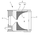
- FIG. 1 shows a first embodiment of the present invention.
- a laser-driven lamp 1 is composed of a columnar body 2, a light exit window 3 provided on the front and rear surfaces thereof, and a light entrance window 4.
- the body portion 2 is made of a ceramic material such as polycrystalline alumina (Al 2 O 3 ).
- a concave reflecting portion 5 is formed on the front side of the body portion 2, and a laser beam passage hole 6 penetrating the concave reflecting portion 5 in the optical axis direction is formed at the center thereof.
- the laser beam passage hole 6 is chamfered at the rear end side, that is, the incident side, to form a tapered portion 6a.
- the tapered portion 6 a is blocked by being kicked on the incident side of the laser beam passage hole 6 when the condensed laser beam is introduced through the light incident window 4 and guided to the laser beam passage hole 6. Is to prevent.
- the concave reflecting portion 5 is configured by a parabolic shape or an elliptical shape, and is described as a parabolic reflecting portion in this embodiment.
- the concave reflection portion 5 is formed of a metal vapor deposition film in which aluminum or the like is vapor deposited on the concave surface portion of the body portion 2 or a dielectric multilayer film.
- the light exit window 3 provided in front of the concave reflecting portion 5 is ultraviolet light transmissive, and the rear light incident window 4 is laser light transmissive, both of which are made of a crystal material such as quartz or sapphire.
- the outer peripheral surfaces of the light exit window 3 and the light entrance window 4 are coated with a metal made of, for example, a mixture of molybdenum and manganese and metallized.
- the front and rear end portions of the outer periphery of the body portion 2 are also subjected to metallization processing in the same manner as the light exit window 3 and the light entrance window 4.
- the light exit window 3 whose outer peripheral surface is metallized is joined to an elastic metal ring member 10 by brazing with silver brazing or the like, while a metallized front end of the body 2 is made of metal.
- the window mounting cylinder 11 is joined by brazing.
- the ring member 10 and the window mounting cylinder 11 are welded together by TIG welding, laser welding, or the like. Thereby, the light emission window 3 is attached to the front side of the body part 2.
- the light incident window 4 whose outer peripheral surface is metallized is joined to the metal block 12 by brazing, and a metal window mounting cylinder 13 is joined to the metallized rear end of the body part 2 by brazing.
- the metal block 12 and the window mounting cylinder 13 are welded together by TIG welding, laser welding, or the like.
- the light incident window 4 is attached to the rear surface side of the body part 2.
- the body portion 2 assembled in this way, the light exit window 3 and the light entrance window 4 constitute a plasma container, in which a sealed space S is formed, and a luminescent gas is formed in the sealed space S.
- a rare gas such as xenon gas, krypton gas, argon gas, or mercury gas is sealed in accordance with the emission wavelength.
- a gap 14 is formed between the body portion 2 and the metal block 12 and communicates with the sealed space S.
- an exhaust pipe 15 is brazed and fixed to the metal block 12, and the exhaust pipe 15 communicates with the gap 14 and communicates with the sealed space S through the gap 14. After the sealed space S is evacuated through the exhaust pipe 15, the luminescent gas is sealed, and then the end 15 a of the exhaust pipe 15 is pressure-cut and sealed.
- the light exit window 3 may be provided with a laser beam reflecting portion 3a at the center thereof.
- mercury included as the light emission gas
- the laser light is almost absorbed by the generated plasma, but in the case of xenon or the like, the absorptance may be reduced to reach the light exit window 3.
- the laser beam reflecting portion 3a is provided in the light exit window 3, the emission of the laser beam to the outside is prevented.
- laser light L from a laser light generator (not shown) is condensed by a condenser lens 21 and introduced through a light incident window 4.
- the condensing point of the laser beam L is at the focal position F of the concave reflecting portion 5.
- the light emission gas is excited by the plasma generated at the focal position F by the laser light to emit ultraviolet light, and this ultraviolet light (excitation light) EL is reflected by the concave reflecting portion 5 and forwards through the light exit window 3. It is emitted.
- the body portion 2 is entirely composed of ceramics.
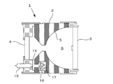
- FIG. 2 shows another second embodiment, and the body portion 2 is made of a ceramic body. It consists of a part main body 2a and a metal reflecting part forming part 2b incorporated therein, and a concave reflecting part 5 is formed on the reflecting part forming part 2b.
- This reflection part formation part 2b is created as a machined part of aluminum, and a reflection surface is manufactured by cutting. Thereby, a more sophisticated reflective surface can be formed mechanically and optically.
- FIG. 3 shows still another third embodiment in which the entire body portion 2 is made of a metal member such as aluminum.
- a metal member such as aluminum.
- drum 2 is improved and the deterioration characteristic of a reflective surface is improved.
- a dielectric multilayer film or the like may be added to the reflecting surface.
- the entire body portion 2 is made of metal, the impure gas discharged from the body portion 2 increases with lighting, so a getter housing space 16 is formed in the body portion 2 to accommodate the getter material 17.
- the sealed space S may be communicated with the gap 14.
- Body part (2) made of polycrystalline alumina (Al 2 O 3 ), total length 22 mm, outer diameter 32 mm ⁇ Filled gas: xenon gas 2.0MPa (25 °C conversion)
- Light incident window member (4) made of sapphire, outer diameter 15 mm, thickness 3 mm -Light exit window member (3): made of sapphire, outer diameter 32 mm, thickness 3 mm ⁇ Ring member (10): Kovar ⁇ Window mounting cylinder (11, 13): Kovar, outer diameter 33 mm, wall thickness 0.5 mm
- the light incident window 4 is attached to the body portion 2 with the metal block 12 interposed therebetween.
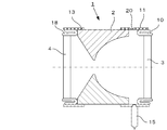
- An attachment structure similar to the structure for attaching the window 3 to the body portion 2 may be used. That is, in the fourth embodiment shown in FIG. 4, the elastic metal ring member 18 joined to the light incident window 4 by brazing is attached to the metal window mounting cylinder 13 joined to the body portion 2. It is welded. Thereby, the light incident window 4 is attached to the body part 2.
- the solid angle of incidence of the laser light L incident from the light incident window 4 can be increased, and the enclosed space S of the laser driving lamp 1 can be increased.
- a high density plasma can be obtained by increasing the energy density applied to the generated plasma.
- the exhaust pipe 15 described above can be attached to the window attachment cylinder 13 of the light incident window 4 by brazing, and communicates with the inside of the sealed space S.
- the other configuration is the same as that of the first embodiment of FIG. FIG. 5 shows another fifth embodiment.
- the exhaust pipe 15 is attached to the window mounting cylinder 11 of the light exit window 3.
- Other configurations are the same as those of the embodiment of FIG. FIG. 6 shows still another sixth embodiment.
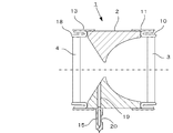
- an exhaust pipe 15 is attached to the body 2, and the exhaust pipe 15 is communicated with the body 2 in the sealed space S.
- a communication hole 19 is formed for this purpose.
- a predetermined attachment region of the body portion 2 can be metallized and the exhaust pipe 15 can be attached thereto by brazing.
- Other configurations are the same as those of the embodiment of FIG.
- the exhaust pipe 15 for evacuating the sealed space S and enclosing the luminescent gas is attached to the body 2 or the window mounting cylinders 11 and 13, so that the incident window Since the laser beam L incident from 4 is not shielded by the exhaust pipe 15, the incident solid angle can be maximized without being restricted by the exhaust pipe 15. Therefore, the energy density input to the plasma can be increased.
- the pressure in the sealed space rises in the same manner.
- the laser driven lamp bursts.
- the gas in the sealed space is in a high pressure and high temperature state of, for example, 20 atm when sealed and 40 to 60 atm when lit, and if the laser-driven lamp bursts, the fragments will have a considerable speed and kinetic energy. Scatters in all directions, collides with a lens arranged in front of the laser-driven lamp and a reflecting mirror arranged around it, damaging these optical devices.
- vacuum ultraviolet light there is a problem that expensive magnesium fluoride MgF or calcium fluoride CaF 2 is used for the lens and window material, and these members are instantly damaged.
- a laser relief lamp is provided with a pressure relief part, and when the pressure in the sealed space rises abnormally, the pressure is released at a predetermined location and opened.
- 7 to 11 show embodiments in which damage to other components constituting the driving lamp and damage to surrounding optical systems are reduced.
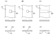
- FIG. 8 shows various forms of the concave portion (pressure relief portion) 20.
- A) is a quadrangular recess
- B) is a circular recess
- C) is a slit-shaped recess that crosses the window mounting cylinder 13.
- the cross-sectional shape of the concave portion may be a hemispherical shape shown in (D) other than a square shape, or may be a V shape (conical shape) shown in (E).
- the recessed part 20 may be formed in the inner surface side of the window attachment cylinder 13.
- FIG. 9 shows the operating state of the pressure relief portion 20, and the normal pressure state is a steady state shown in FIG. 9A, and when the pressure inside the sealed space increases due to an abnormality, As shown, the thin pressure relief 20 is inflated and broken to release the pressure.
- the pressure relief portion 20 is provided in the window mounting cylinder 13 of the light incident window 4, but as shown in the eighth embodiment of FIG. You may provide in the attachment cylinder 11. Further, in these embodiments, the structure in which the exhaust pipe 15 is attached to the window mounting cylinders 11 and 13 in which the pressure relief part 20 is formed is shown, but the present invention is not limited to this, and the pressure relief part 20 and the exhaust pipe 15 are not limited thereto. It is good also as a structure attached to the separate window attachment cylinders 11 and 13, respectively.
- FIG. 11 shows another ninth embodiment.
- a pressure relief portion 20 is formed in the exhaust pipe 15.
- the exhaust pipe 15 is attached to the body portion 2, and a communication hole 19 for communicating the exhaust pipe 15 into the sealed space S is formed in the body portion 2.
- a predetermined attachment region of the ceramic body 2 can be metallized, and the exhaust pipe 15 can be attached thereto by brazing.
- a thin pressure relief portion 20 is formed in the exhaust pipe 15.
- the exhaust pipe 15 forming the pressure relief portion 20 is provided with a window mounting cylinder 13 of the light incident window 4 as shown in FIG. 7, or a window mounting cylinder of the light emission window 3 as shown in FIG. 11 may be attached. Furthermore, the pressure relief 20 may be formed in the exhaust pipe 15 attached to the metal block 12 to which the light incident window 4 is attached in the first embodiment shown in FIG.
- the pressure relief part in the laser drive lamp, even if the inside of the sealed space becomes an abnormally high pressure state, the pressure relief part is damaged, so that the predetermined part specified in advance can be obtained.
- the high pressure is released to prevent other components constituting the laser-driven lamp from being damaged, and the surrounding optical system is not damaged.
- a laser beam L from a laser beam generator enters the sealed space S of the laser driving lamp 1 from the light incident window 4. Due to the difference in refractive index from the atmosphere (for example, air), a part of the laser beam may be reflected. Part of the reflected laser light travels from the light incident window 4 toward the laser light generator along a path opposite to the incident path. The reflected laser light returning to the laser light generator may cause the medium in the laser light generator to be overheated and eventually damage the laser light generator.
- the laser light reflected by the light incident window returns to the laser light generator by tilting the incident surface of the light incident window of the laser driving lamp with respect to the optical path of the laser light.
- 12 and 13 show an embodiment in which the incident light does not enter.
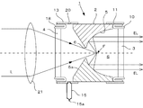
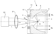
- FIG. 12 shows a tenth embodiment in which the light incident window 4 of the laser driving lamp 1 is provided to be inclined with respect to the optical path (optical axis) LA of the laser light L, and the incident surface 4a is the optical path LA. It is inclined with respect to.
- the rotation center axis X of the concave reflecting portion 5 in the laser driving lamp 1 coincides with the optical axis LA of the laser light L from the laser light generator 22 and the condenser lens 21, and from the laser light generator 22.
- the laser beam L is incident on the light incident window 4 of the laser driving lamp 1 while being condensed by the condensing unit 21 and is condensed on the focal position F of the concave reflecting portion 5.
- plasma is generated around the focal position F in the sealed space S, and the excitation light EL generated by exciting the luminescent gas is reflected by the concave reflecting portion 5 and emitted to the outside from the light exit window 3. .
- the incident surface 4a of the light incident window 4 is inclined with respect to the optical path LA of the laser light L. Since the reflected light RL reflected by the incident surface 4a is reflected in a direction different from the optical path of the laser light L, the reflected light RL does not return to the laser light generator 22 and enter.
- the optical axis LA of the laser light L from the laser light generator 22 and the rotation center axis X of the concave reflecting portion 5 of the laser driving lamp 1 coincide with each other and the light incident window 4 is incident.
- the surface 4a is inclined with respect to the optical axis LA of the laser beam L.
- the rotation center axis X of the concave reflecting portion 5 can be angled with respect to the optical axis LA of the laser beam L.
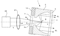
- the rotation center axis X of the concave reflecting portion 5 of the body portion 2 in the laser drive lamp 1 is inclined with an angle with the optical axis LA of the laser beam L from the laser beam generator 22. is doing.
- the laser driving lamp 1 is tilted by rotating around the focal position (condensing position) F on the optical axis LA of the laser light L.
- the light incident window 4 is attached such that the incident surface 4 a thereof is orthogonal to the rotation center axis X of the concave reflecting portion 5. Thereby, the incident surface 4a of the light incident window 4 is inclined with respect to the optical axis LA of the laser light L.
- the laser light L from the laser light generator 22 is incident from the incident surface 4a of the light incident window 4, but the reflected light RL at that time does not travel toward the laser light generator 22.
- the laser light L is condensed at the focal position F of the concave reflecting portion 5 in the laser driving lamp 1 to generate plasma.
- the excitation light EL generated thereby is reflected by the concave reflecting portion 5 and has an angle with the optical axis LA of the laser light L, and the light exit window 3 along the rotation center axis X of the concave reflecting portion 5. It is emitted from.
- the incident surface of the light incident window in the laser driving lamp is inclined with respect to the optical path of the laser light from the laser light generator, the laser light reflected by the incident surface is incident on the laser. Since the light beam is directed in a direction different from the optical path, the light beam does not enter the laser beam generator and can be prevented from being damaged by components such as a medium in the laser beam generator.
- a plasma generating container is formed by providing a light exit window and a light entrance window before and after the columnar body portion, and a sealed space is formed therein,
- ceramics and metals other than quartz glass can be used for the fuselage, light exit window, and light entrance window that make up the laser-driven lamp. Even when irradiated with UV light or VUV light, ultraviolet distortion is not generated in the laser driving lamp, and a laser driving lamp with higher output and longer life can be realized.
- the pressure relief part even if the sealed space is in an abnormally high pressure state, the pressure relief part can be damaged, so that the high pressure can be released at a predetermined part specified in advance. And other components and optical components are not damaged. Further, by providing the incident surface of the light incident window to be inclined with respect to the optical path of the laser light from the laser light generator, the laser light reflected by the light incident window does not return to the laser light generator, There is no such thing as damaging it.
Landscapes
- Physics & Mathematics (AREA)
- Engineering & Computer Science (AREA)
- Plasma & Fusion (AREA)
- Electromagnetism (AREA)
- Non-Portable Lighting Devices Or Systems Thereof (AREA)
- Optics & Photonics (AREA)
Abstract
Dans une lampe à excitation laser qui est remplie d'un gaz électroluminescent et dans laquelle du plasma est généré en concentrant et en introduisant un faisceau laser dans la lampe, la présente invention aborde le problème de réalisation d'une structure de prévention de l'apparition de contrainte en raison des rayons ultraviolets grâce à l'utilisation d'un matériau autre que le verre de quartz pour une ampoule de plasma. Une lampe à excitation laser (1) est caractérisée en ce qu'elle comporte une section de corps (2) en colonne et est caractérisée en ce qu'une section réfléchissante (5) concave ayant un point focal sur lequel est concentré le faisceau laser est formée à l'avant de la section de corps (2), qu'une fenêtre d'émission de lumière (3) transparente aux ultraviolets est installée dans la face avant de la section réfléchissante (5) concave, qu'un trou d'émission (6) de faisceau laser traversant dans une direction d'axe optique est percé au centre de la section de corps (2), qu'une fenêtre d'entrée de lumière (4) à travers laquelle est introduit le faisceau laser est installée dans l'arrière de la section de corps (2), que la section de corps (2), la fenêtre d'émission de lumière (3) et la fenêtre d'entrée de lumière (3) forment un espace clos (S), et que l'espace clos (S) est rempli du gaz électroluminescent.
Priority Applications (2)
| Application Number | Priority Date | Filing Date | Title |
|---|---|---|---|
| CN201780011301.6A CN108604531B (zh) | 2016-02-23 | 2017-01-31 | 激光驱动灯 |
| US16/078,251 US10561008B2 (en) | 2016-02-23 | 2017-01-31 | Laser driven lamp |
Applications Claiming Priority (8)
| Application Number | Priority Date | Filing Date | Title |
|---|---|---|---|
| JP2016031798A JP6233616B2 (ja) | 2016-02-23 | 2016-02-23 | レーザ駆動ランプ |
| JP2016-031798 | 2016-02-23 | ||
| JP2016096667A JP6390863B2 (ja) | 2016-05-13 | 2016-05-13 | レーザ駆動光源装置 |
| JP2016-096667 | 2016-05-13 | ||
| JP2016-176110 | 2016-09-09 | ||
| JP2016176110A JP6440102B2 (ja) | 2016-09-09 | 2016-09-09 | レーザ駆動ランプ |
| JP2016-223941 | 2016-11-17 | ||
| JP2016223941A JP6776837B2 (ja) | 2016-11-17 | 2016-11-17 | レーザ駆動ランプ |
Publications (1)
| Publication Number | Publication Date |
|---|---|
| WO2017145662A1 true WO2017145662A1 (fr) | 2017-08-31 |
Family
ID=59685671
Family Applications (1)
| Application Number | Title | Priority Date | Filing Date |
|---|---|---|---|
| PCT/JP2017/003334 Ceased WO2017145662A1 (fr) | 2016-02-23 | 2017-01-31 | Lampe à excitation laser |
Country Status (3)
| Country | Link |
|---|---|
| US (1) | US10561008B2 (fr) |
| CN (1) | CN108604531B (fr) |
| WO (1) | WO2017145662A1 (fr) |
Cited By (2)
| Publication number | Priority date | Publication date | Assignee | Title |
|---|---|---|---|---|
| US20220200225A1 (en) * | 2020-12-21 | 2022-06-23 | Hamamatsu Photonics K.K | Light emitting sealed body and light source device |
| JP7650777B2 (ja) | 2021-10-04 | 2025-03-25 | 浜松ホトニクス株式会社 | 発光封体及び光源装置 |
Families Citing this family (11)
| Publication number | Priority date | Publication date | Assignee | Title |
|---|---|---|---|---|
| US11972931B2 (en) | 2020-12-21 | 2024-04-30 | Hamamatsu Photonics K.K. | Light emitting sealed body, light emitting unit, and light source device |
| US11367989B1 (en) | 2020-12-21 | 2022-06-21 | Hamamatsu Photonics K.K. | Light emitting unit and light source device |
| US11587781B2 (en) | 2021-05-24 | 2023-02-21 | Hamamatsu Photonics K.K. | Laser-driven light source with electrodeless ignition |
| JP7650776B2 (ja) * | 2021-10-04 | 2025-03-25 | 浜松ホトニクス株式会社 | 発光封体、光源装置、及び発光封体の駆動方法 |
| JP7648496B2 (ja) * | 2021-10-04 | 2025-03-18 | 浜松ホトニクス株式会社 | 発光封体及び光源装置 |
| JP7648495B2 (ja) * | 2021-10-04 | 2025-03-18 | 浜松ホトニクス株式会社 | 発光封体及び光源装置 |
| WO2023059228A1 (fr) | 2021-10-08 | 2023-04-13 | Isteq B.V. | Source de lumière à plasma à pompage laser à large bande |
| US12165856B2 (en) | 2022-02-21 | 2024-12-10 | Hamamatsu Photonics K.K. | Inductively coupled plasma light source |
| US12144072B2 (en) | 2022-03-29 | 2024-11-12 | Hamamatsu Photonics K.K. | All-optical laser-driven light source with electrodeless ignition |
| US12156322B2 (en) | 2022-12-08 | 2024-11-26 | Hamamatsu Photonics K.K. | Inductively coupled plasma light source with switched power supply |
| US12578076B2 (en) | 2023-06-05 | 2026-03-17 | Hamamatsu Photonics K.K. | Dual-output laser-driven light source |
Citations (3)
| Publication number | Priority date | Publication date | Assignee | Title |
|---|---|---|---|---|
| JP2010097699A (ja) * | 2008-10-14 | 2010-04-30 | Ushio Inc | ショートアークランプ |
| JP2010538412A (ja) * | 2007-11-16 | 2010-12-09 | セラビジョン・リミテッド | マイクロ波で駆動される光源 |
| JP2013026161A (ja) * | 2011-07-25 | 2013-02-04 | Sharp Corp | 光源装置、照明装置、車両用前照灯および車両 |
Family Cites Families (8)
| Publication number | Priority date | Publication date | Assignee | Title |
|---|---|---|---|---|
| JPH03258481A (ja) | 1990-03-09 | 1991-11-18 | Toshiba Corp | レーザマーキング装置 |
| US7435982B2 (en) * | 2006-03-31 | 2008-10-14 | Energetiq Technology, Inc. | Laser-driven light source |
| KR101278425B1 (ko) | 2008-12-27 | 2013-06-24 | 에너제틱 테크놀로지 아이엔씨. | 광원 장치 |
| JP5550855B2 (ja) * | 2009-06-12 | 2014-07-16 | 株式会社トプコン | 回転レーザ出射装置 |
| CN103048889B (zh) * | 2012-12-18 | 2015-05-20 | 华中科技大学 | 一种基于圆偏振激光驱动的极紫外光刻光源产生系统 |
| US8853655B2 (en) | 2013-02-22 | 2014-10-07 | Kla-Tencor Corporation | Gas refraction compensation for laser-sustained plasma bulbs |
| KR101953712B1 (ko) * | 2013-12-13 | 2019-05-17 | 에이에스엠엘 네델란즈 비.브이. | 방사선 소스, 계측 장치, 리소그래피 시스템 및 디바이스 제조 방법 |
| US9748086B2 (en) * | 2014-05-15 | 2017-08-29 | Excelitas Technologies Corp. | Laser driven sealed beam lamp |
-
2017
- 2017-01-31 US US16/078,251 patent/US10561008B2/en not_active Expired - Fee Related
- 2017-01-31 CN CN201780011301.6A patent/CN108604531B/zh not_active Expired - Fee Related
- 2017-01-31 WO PCT/JP2017/003334 patent/WO2017145662A1/fr not_active Ceased
Patent Citations (3)
| Publication number | Priority date | Publication date | Assignee | Title |
|---|---|---|---|---|
| JP2010538412A (ja) * | 2007-11-16 | 2010-12-09 | セラビジョン・リミテッド | マイクロ波で駆動される光源 |
| JP2010097699A (ja) * | 2008-10-14 | 2010-04-30 | Ushio Inc | ショートアークランプ |
| JP2013026161A (ja) * | 2011-07-25 | 2013-02-04 | Sharp Corp | 光源装置、照明装置、車両用前照灯および車両 |
Cited By (4)
| Publication number | Priority date | Publication date | Assignee | Title |
|---|---|---|---|---|
| US20220200225A1 (en) * | 2020-12-21 | 2022-06-23 | Hamamatsu Photonics K.K | Light emitting sealed body and light source device |
| US11862922B2 (en) * | 2020-12-21 | 2024-01-02 | Energetiq Technology, Inc. | Light emitting sealed body and light source device |
| US12191623B2 (en) * | 2020-12-21 | 2025-01-07 | Hamamatsu Photonics K.K. | Light emitting sealed body and light source device |
| JP7650777B2 (ja) | 2021-10-04 | 2025-03-25 | 浜松ホトニクス株式会社 | 発光封体及び光源装置 |
Also Published As
| Publication number | Publication date |
|---|---|
| CN108604531B (zh) | 2020-09-18 |
| US10561008B2 (en) | 2020-02-11 |
| US20190053364A1 (en) | 2019-02-14 |
| CN108604531A (zh) | 2018-09-28 |
Similar Documents
| Publication | Publication Date | Title |
|---|---|---|
| WO2017145662A1 (fr) | Lampe à excitation laser | |
| US10609804B2 (en) | Laser driven lamp | |
| TWI469196B (zh) | Exposure device | |
| US9775226B1 (en) | Method and system for generating a light-sustained plasma in a flanged transmission element | |
| US10497555B2 (en) | Laser driven sealed beam lamp with improved stability | |
| KR20100114455A (ko) | 레이저 구동 광원 | |
| KR20010110145A (ko) | 방전램프, 램프 유닛 및 화상표시장치 | |
| JP6233616B2 (ja) | レーザ駆動ランプ | |
| JP6776837B2 (ja) | レーザ駆動ランプ | |
| JP6978718B2 (ja) | レーザ駆動光源 | |
| JP2017220439A (ja) | レーザ駆動光源装置 | |
| JP2017220319A (ja) | レーザ駆動光源装置 | |
| JP3183145B2 (ja) | ショートアークランプ | |
| US11682548B2 (en) | Light emitting sealed body and light source device | |
| JP6390863B2 (ja) | レーザ駆動光源装置 | |
| JP6440102B2 (ja) | レーザ駆動ランプ | |
| WO2017212710A1 (fr) | Dispositif de source de lumière à entraînement laser | |
| JP4466198B2 (ja) | 光源装置 | |
| JPH08111551A (ja) | レーザ用アパーチャ及びそれを用いたレーザ発振器 | |
| US11676809B2 (en) | Light emitting sealed body and light source device | |
| US11664211B2 (en) | Light emitting sealed body, light source device, and method for driving light emitting sealed body | |
| JP2017216125A (ja) | レーザ駆動ランプ | |
| US11670497B2 (en) | Light emitting sealed body and light source device | |
| JP4609224B2 (ja) | 光源装置 | |
| WO2017212683A1 (fr) | Dispositif de source de lumière à entraînement laser |
Legal Events
| Date | Code | Title | Description |
|---|---|---|---|
| NENP | Non-entry into the national phase |
Ref country code: DE |
|
| 121 | Ep: the epo has been informed by wipo that ep was designated in this application |
Ref document number: 17756104 Country of ref document: EP Kind code of ref document: A1 |
|
| 122 | Ep: pct application non-entry in european phase |
Ref document number: 17756104 Country of ref document: EP Kind code of ref document: A1 |