WO2017145916A1 - Transmission automatique - Google Patents
Transmission automatique Download PDFInfo
- Publication number
- WO2017145916A1 WO2017145916A1 PCT/JP2017/005788 JP2017005788W WO2017145916A1 WO 2017145916 A1 WO2017145916 A1 WO 2017145916A1 JP 2017005788 W JP2017005788 W JP 2017005788W WO 2017145916 A1 WO2017145916 A1 WO 2017145916A1
- Authority
- WO
- WIPO (PCT)
- Prior art keywords
- pressure
- hydraulic
- hydraulic chamber
- piston
- fastening
- Prior art date
- Legal status (The legal status is an assumption and is not a legal conclusion. Google has not performed a legal analysis and makes no representation as to the accuracy of the status listed.)
- Ceased
Links
Images


Classifications
-
- F—MECHANICAL ENGINEERING; LIGHTING; HEATING; WEAPONS; BLASTING
- F16—ENGINEERING ELEMENTS AND UNITS; GENERAL MEASURES FOR PRODUCING AND MAINTAINING EFFECTIVE FUNCTIONING OF MACHINES OR INSTALLATIONS; THERMAL INSULATION IN GENERAL
- F16D—COUPLINGS FOR TRANSMITTING ROTATION; CLUTCHES; BRAKES
- F16D25/00—Fluid-actuated clutches
- F16D25/06—Fluid-actuated clutches in which the fluid actuates a piston incorporated in, i.e. rotating with the clutch
- F16D25/062—Fluid-actuated clutches in which the fluid actuates a piston incorporated in, i.e. rotating with the clutch the clutch having friction surfaces
- F16D25/063—Fluid-actuated clutches in which the fluid actuates a piston incorporated in, i.e. rotating with the clutch the clutch having friction surfaces with clutch members exclusively moving axially
- F16D25/0635—Fluid-actuated clutches in which the fluid actuates a piston incorporated in, i.e. rotating with the clutch the clutch having friction surfaces with clutch members exclusively moving axially with flat friction surfaces, e.g. discs
- F16D25/0638—Fluid-actuated clutches in which the fluid actuates a piston incorporated in, i.e. rotating with the clutch the clutch having friction surfaces with clutch members exclusively moving axially with flat friction surfaces, e.g. discs with more than two discs, e.g. multiple lamellae
-
- F—MECHANICAL ENGINEERING; LIGHTING; HEATING; WEAPONS; BLASTING
- F16—ENGINEERING ELEMENTS AND UNITS; GENERAL MEASURES FOR PRODUCING AND MAINTAINING EFFECTIVE FUNCTIONING OF MACHINES OR INSTALLATIONS; THERMAL INSULATION IN GENERAL
- F16D—COUPLINGS FOR TRANSMITTING ROTATION; CLUTCHES; BRAKES
- F16D48/00—External control of clutches
- F16D48/02—Control by fluid pressure
Definitions
- the present invention relates to an automatic transmission having a frictional engagement element including a plurality of friction plates and a piston.
- An automatic transmission mounted on a vehicle such as an automobile includes a planetary gear set and a plurality of frictional engagement elements such as a multi-plate clutch and a multi-plate brake.
- a plurality of frictional engagement elements are selectively engaged according to the operating state of the engine, thereby automatically shifting to a predetermined gear stage.
- the frictional engagement element includes a plurality of friction plates arranged with a clearance, and a piston that presses the friction plates. The piston moves between a fastening position where the friction plates are pressed to bring the friction plates into a fastening state and a release position where the friction plates are released to release the pressure.
- a fastening hydraulic chamber is disposed on one side of the piston in the axial direction
- a centrifugal hydraulic chamber release hydraulic chamber
- the fastening hydraulic chamber and the centrifugal hydraulic chamber are communicated with the piston.
- An automatic transmission provided with a communication hole is disclosed.
- a predetermined hydraulic pressure is supplied to the fastening hydraulic chamber and the centrifugal hydraulic chamber from separate oil passages.
- a pressure regulating valve is incorporated in the oil passage for the centrifugal hydraulic chamber.
- An object of the present invention is to provide an automatic transmission including a frictional engagement element that can reduce engagement shock without requiring complicated hydraulic control and can shorten the engagement control time.
- An automatic transmission has a first surface and a second surface facing each other in the axial direction, and is disposed on the first surface side of the piston, which is movable in the axial direction.
- a plurality of friction plates, and a fastening hydraulic chamber for applying hydraulic pressure to the second surface of the piston and directing the piston to a fastening position that presses the friction plates so that the friction plates are in a fastening state;
- a release hydraulic chamber for applying hydraulic pressure to the first surface of the piston and directing the piston to a release position for releasing the friction plates; and a hydraulic output port; the fastening hydraulic chamber;
- a hydraulic control valve that supplies and discharges hydraulic pressure to each of the release hydraulic chambers, a first oil passage that connects the output port of the hydraulic control valve and the fastening hydraulic chamber, and the output port And the release hydraulic chamber Comprising a second oil passage for communicating, the.
- the pressure receiving area of the hydraulic pressure on the second surface of the piston is set larger than the pressure receiving area of the hydraulic pressure on the first
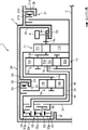
- FIG. 1 is a skeleton diagram of an automatic transmission according to an embodiment of the present invention.
- FIG. 2 is a fastening table of frictional engagement elements provided in the automatic transmission.
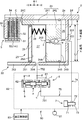
- FIG. 3 is one of the frictional engagement elements, and is a diagram showing a schematic cross-section of the configuration of the brake according to the embodiment of the present invention and the block configuration of the hydraulic mechanism.
- FIG. 4 is a schematic cross-sectional view for explaining the operation of the brake.
- FIG. 5 is a schematic cross-sectional view for explaining the operation of the brake.
- FIG. 6 is a schematic cross-sectional view for explaining the operation of the brake.
- FIG. 7 is a schematic cross-sectional view for explaining the operation of the brake.
- FIG. 8 is a schematic cross-sectional view for explaining the operation of the brake.
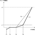
- FIG. 9 is a graph showing the relationship between the applied hydraulic pressure and the change in brake engagement pressure.
- FIG. 10 is a diagram showing a schematic cross-section of the configuration of the clutch according to the first modified embodiment of the present invention and a block configuration of the hydraulic mechanism, which is one of the frictional engagement elements.
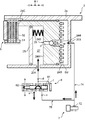
- FIG. 11 is a diagram showing a schematic cross-section of a configuration of a brake according to a second modified embodiment of the present invention and a block configuration of the hydraulic mechanism.
- FIG. 1 is a skeleton diagram showing a configuration of an automatic transmission 1 for an automobile (vehicle) according to an embodiment of the present invention.
- the automatic transmission 1 includes a transmission case 2, an input shaft 3 disposed in the transmission case 2 extending from the engine side, an output gear 4, and four planetary gear sets (first and second gear mechanisms) as a transmission mechanism. 2, 3, and 4 planetary gear sets 11, 12, 13, and 14), two brakes (first and second brakes 21 and 22), and three clutches (first, second, and third clutches 31, 32, 33).
- the input shaft 3 is an axis to which power generated by the engine is input.
- the output gear 4 is a gear that outputs a driving force having a predetermined gear ratio by the transmission mechanism.
- a so-called torque converter-less automatic transmission in which engine power is input to the input unit without passing through a torque converter (fluid transmission) is illustrated.
- the transmission case 2 includes an outer peripheral wall 2a, a first intermediate wall 2b provided at the engine side end of the outer peripheral wall 2a, a second intermediate wall 2c provided on the opposite side of the first intermediate wall 2b from the engine, A third intermediate wall 2d provided at the axially intermediate portion of the outer peripheral wall 2a, a side wall 2e provided at the opposite end of the outer peripheral wall 2a on the engine side, and a boss extending from the central portion of the side wall 2e to the engine side Part 2f and a cylindrical part 2g extending from the inner peripheral side end of the second intermediate wall 2c to the non-engine side.
- the four planetary gear sets 11 to 14 are, from the engine side, the first planetary gear set 11, the second planetary gear set 12 on the inner circumferential side and the third planetary gear set 13 on the outer circumferential side, and the fourth planetary gear set 13 that are arranged to overlap each other in the radial direction.
- the planetary gear set 14 is arranged in this order.
- the first planetary gear set 11 includes a carrier 11c, a pinion (not shown) supported by the carrier 11c, a sun gear 11s, and a ring gear 11r.
- the first planetary gear set 11 is a single pinion type in which the pinion directly meshes with the sun gear 11s and the ring gear 11r.
- the second, third, and fourth planetary gear sets 12, 13, and 14 are also single pinion type, and carriers 12c, 13c, and 14c, an unillustrated pinion, sun gears 12s, 13s, and 14s, and ring gears 12r, 13r, and 14r. Including.
- the ring gear 12r of the second planetary gear set 12 and the sun gear 13s of the third planetary gear set 13 that are arranged in two stages in the radial direction are integrated by welding or shrink fitting. That is, the ring gear 12r and the sun gear 13s are always connected to form an integral rotating element 15.
- the carriers 13c are always connected to each other.
- the input shaft 3 is always connected to the carrier 12 c of the second planetary gear set 12.
- the output gear 4 is always connected to the carrier 11c of the first planetary gear set 11 and the carrier 13c of the third planetary gear set 13, respectively.
- the output gear 4 is rotatably supported by the cylindrical portion 2g of the transmission case 2 via a bearing 41.
- the first rotating member 34 is connected to the sun gear 14 s of the fourth planetary gear set 14.
- the first rotating member 34 extends to the non-engine side.
- the second rotating member 35 is connected to the ring gear 13 r of the third planetary gear set 13, and the third rotating member 36 is connected to the integral rotating element 15.
- These rotating members 34 and 35 also extend to the non-engine side.
- a fourth rotating member 37 is connected to the carrier 12 c of the second planetary gear set 12 via the input shaft 3.
- the first brake 21 is disposed on the first intermediate wall 2 b of the transmission case 2.
- the first brake 21 includes a cylinder 211, a piston 212 fitted in the cylinder 211, and a working hydraulic chamber 213 defined by the cylinder 211 and the piston 212.
- the first brake 21 is engaged with the friction plate by supplying a predetermined engagement hydraulic pressure to the hydraulic operating chamber 213, and the sun gear 11s of the first planetary gear set 11 and the sun gear 12s of the second planetary gear set 12 are connected to the transmission case. Fix to 2.
- the second brake 22 is disposed on the third intermediate wall 2d.
- the second brake 22 includes a cylinder 23, a piston 24 fitted to the cylinder 23, and a fastening hydraulic chamber 26 defined by the cylinder 23 and the piston 24.
- the second brake 22 is fastened to a friction plate by supplying a predetermined fastening hydraulic pressure to the fastening hydraulic chamber 26, and fixes the ring gear 14 r of the fourth planetary gear set 14 to the transmission case 2.
- a frictional engagement element having the characteristics of the present invention is applied to the second brake 22 will be described.
- the second brake 22 will be described in detail later with reference to FIG.
- the first to third clutches 31 to 33 are disposed at the end on the side opposite to the engine in the transmission case 2.
- the second clutch 32 is located on the inner peripheral side of the first clutch 31 and the third clutch 33 is located on the inner peripheral side of the second clutch 32 at the same axial position. Thus, they are arranged so as to overlap each other in the radial direction.
- the first clutch 31 connects and disconnects the sun gear 14s of the fourth planetary gear set 14 and the ring gear 13r of the third planetary gear set 13. In other words, the connection state between the first rotating member 34 connected to the sun gear 14s and the second rotating member 35 connected to the ring gear 13r is switched.
- the second clutch 32 connects and disconnects the sun gear 14s of the fourth planetary gear set 14 and the integral rotating element 15 (that is, the ring gear 12r of the second planetary gear set 12 and the sun gear 13s of the third planetary gear set 13). In other words, the connection state between the first rotating member 34 connected to the sun gear 14 s and the third rotating member 36 connected to the integral rotating element 15 is switched.
- the third clutch 33 connects and disconnects the sun gear 14s of the fourth planetary gear set 14 and the carrier 12c of the input shaft 3 and the second planetary gear set 12. In other words, the connection state between the first rotating member 34 connected to the sun gear 14s and the fourth rotating member 37 connected to the carrier 12c via the input shaft 3 is switched.
- connection state of the first rotation member 34 with the second rotation member 35 is switched by the first clutch 31, the connection state with the third rotation member 36 is switched by the second clutch 32, and the fourth clutch 33 is switched by the third clutch 33.
- the connection state with the rotating member 37 is switched. That is, the first rotating member 34 is one rotating member that is common among the two rotating members in which the clutches 31 to 33 switch the connected state. Therefore, a shared rotating member 30 having a wall portion orthogonal to the shaft center is disposed on the opposite side of the first to third clutches 31 to 33 in the vicinity of the side wall 2e of the transmission case 2. The first rotating member 34 is connected to the shared rotating member 30.
- the common rotating member 30 is shared by the first to third clutches 31 to 33, and the cylinders, pistons, operating hydraulic chambers, operating hydraulic passages, centrifugal balance hydraulic chambers, and centrifugal balances included in the clutches 31 to 33 are provided.
- a chamber constituent member or the like is supported by the common rotating member 30.
- the pistons 31p, 32p, and 33p of the first, second, and third clutches 31, 32, and 33 are simply illustrated.
- a common member 38 that holds the friction plates of these clutches is assembled to the second clutch 32 and the third clutch 33.
- the automatic transmission 1 includes the first to fourth planetary gear sets 11 to 14, the first and second brakes 21 and 22 and the first to third clutches as the five frictional engagement elements.
- FIG. 2 is a fastening table of five frictional engagement elements provided in the automatic transmission 1. As shown in the engagement table of FIG. 2, the first to eighth forward speeds and the reverse speed are achieved by selectively fastening (circle) three friction engagement elements from five friction engagement elements.
- CL1, CL2, and CL3 indicate first, second, and third clutches 31 to 33
- BR1 and BR2 indicate first and second brakes 21 and 22, respectively.
- FIG. 3 is a schematic cross section showing the configuration of the frictional engagement element of the automatic transmission 1 according to the embodiment of the present invention and a block configuration diagram of the hydraulic mechanism.
- the friction engagement element is applied to the second brake 22 is shown.
- the axial direction of the input shaft 3 is shown in the X direction
- the radial direction of the automatic transmission 1 is shown in the Y direction.
- the left side of the drawing is -X and the right side is + X.
- the second brake 22 is a frictional engagement element disposed in the cylinder 23 formed by the third intermediate wall 2d as described above, and includes the piston 24, the seal ring 25, the engagement hydraulic chamber 26, the release hydraulic chamber 27, and the return.
- a spring 28 and a friction plate unit 5 are provided.
- a hydraulic mechanism 80 is attached to such second brake 22.
- the hydraulic mechanism 80 includes an oil pump 81, a hydraulic circuit 82 including the pressure reducing valve 6 and the linear solenoid valve 7 (hydraulic control valve), and a hydraulic control unit 83 that controls the oil pump 81 and the hydraulic circuit 82.
- the third intermediate wall 2d includes a first wall portion 201 extending radially inward from the outer peripheral wall 2a of the transmission case 2 and a first wall portion 201 extending in the axial direction ( ⁇ X direction) from the radially inner edge of the first wall portion 201.
- the two wall portions 202 are formed.
- the outer peripheral wall 2a and the second wall portion 202 are opposed to each other in the radial direction at a predetermined interval.
- a space formed by the outer peripheral wall 2 a, the first wall portion 201, and the second wall portion 202 constitutes the space of the aforementioned cylinder 23 in the second brake 22.
- the first wall 201 is provided with a first supply port 203 for supplying hydraulic pressure to the fastening hydraulic chamber 26.
- the second wall 202 is provided with a second supply port 204 for supplying hydraulic pressure to the release hydraulic chamber 27.
- the piston 24 has a first surface 24A and a second surface 24B that face each other in the axial direction, and is a member that can move in the axial direction between the outer peripheral wall 2a and the second wall portion 202 (inside the cylinder 23). .
- the first surface 24 ⁇ / b> A faces the release hydraulic chamber 27, and the second surface 24 ⁇ / b> B faces the fastening hydraulic chamber 26.
- the piston 24 has a release position (for example, a position shown in FIG. 4) where the friction plate unit 5 is released and a fastening position (position shown in FIG. 8) where the friction plate unit 5 is brought into a fastening state by applying a pressing force. Move between.
- the piston 24 includes a pressing piece 241 adjacent to the outer peripheral wall 2 a, and a pressure receiving piece 242 slidably contacting the outer peripheral wall 2 a and the inner peripheral surface of the second wall portion 202.
- the pressure receiving piece 242 has a communication hole 243 that penetrates the pressure receiving piece 242 in the axial direction.
- a seal member 245 is fitted on the inner peripheral surface and the outer peripheral surface of the pressure receiving piece 242.
- the pressing piece 241 is a portion protruding from the pressure receiving piece 242 to the ⁇ X side, and includes a distal end surface 24C that applies a pressing force to the friction plate unit 5 on the distal end side ( ⁇ X side) in the moving direction.
- the pressure receiving piece 242 is a partition wall that partitions the fastening hydraulic chamber 26 and the release hydraulic chamber 27. However, in the present embodiment, the fastening hydraulic chamber 26 and the release hydraulic chamber 27 can be communicated with each other through the communication hole 243.
- the seal member 245 permits the seal between the inner peripheral surface of the pressure receiving piece 242 and the inner peripheral surface of the second wall portion 202 and the outer peripheral surface and outer periphery of the pressure receiving piece 242 while allowing the piston 24 to move in the axial direction. This is a member for sealing between the inner peripheral surface of the wall 2a.
- the communication hole 243 is a cylindrical hole having a different diameter in the axial direction, and includes a large diameter portion w having a relatively large diameter, a small diameter portion n having a relatively small diameter, and an intermediate portion m between the two.
- the large-diameter portion w is disposed near the second surface 24B of the pressure receiving piece 242, that is, on the fastening hydraulic chamber 26 side.
- the small-diameter portion n is disposed near the first surface 24A, that is, on the release hydraulic chamber 27 side.
- the intermediate portion m is a tapered portion where the inner diameter gradually decreases from the large diameter portion w toward the small diameter portion n.
- a pressure ball 244 (regulator) is arranged to restrict the oil flow from the fastening hydraulic chamber 26 to the release hydraulic chamber 27.
- the pressure ball 244 has an outer diameter that is smaller than the inner diameter of the large diameter portion w and larger than the inner diameter of the small diameter portion n.
- the pressure ball 244 floats in the large diameter portion w and does not restrict the oil flow from the fastening hydraulic chamber 26 toward the release hydraulic chamber 27.
- the pressure ball 244 is locked to the intermediate portion m, thereby closing the communication hole 243.
- the seal ring 25 is an annular flat plate member disposed on the first surface 24 ⁇ / b> A side of the piston 24 so as to face the pressure receiving piece 242.
- the seal ring 25 is disposed between the pressing piece 241 of the piston 24 and the second wall portion 202, and defines the release hydraulic chamber 27 together with these.
- Seal members 251 are attached to the inner and outer peripheral surfaces of the seal ring 25.
- the seal member 251 seals between the outer peripheral edge of the seal ring 25 and the inner peripheral surface of the pressing piece 241, and seals between the inner peripheral surface of the seal ring 25 and the inner peripheral surface of the second wall portion 202. It is a member.
- the fastening hydraulic chamber 26 is a space to which hydraulic pressure for moving the piston 24 in the direction ( ⁇ X direction) toward the fastening position is supplied.
- the fastening hydraulic chamber 26 is a space defined by the first wall 201, the second wall 202, the outer peripheral wall 2 a, and the second surface 24 ⁇ / b> B of the piston 24. That is, the fastening hydraulic chamber 26 applies hydraulic pressure to the second surface 24B, and the hydraulic pressure for directing the piston 24 to a fastening position that presses the friction plate unit 5 so that the friction plate units 5 (friction plates) are in a fastening state. It is a room.
- the release hydraulic chamber 27 is a space to which hydraulic pressure for moving the piston 24 in the direction (+ X) toward the release position is supplied.
- the release hydraulic chamber 27 is a space defined by the second wall 202, the pressing piece 241 of the piston 24, the + X side surface of the seal ring 25, and the first surface 24A of the piston 24.
- the release hydraulic chamber 27 is a hydraulic chamber for applying hydraulic pressure to the first surface 24A and directing the piston 24 to a release position where the friction plate unit 5 is released.
- a return spring 28 that urges the piston 24 in the + X direction is disposed in the release hydraulic chamber 27. When no hydraulic pressure is applied to the fastening hydraulic chamber 26, the return spring 28 moves (returns) the piston 24 in the + X direction.
- the pressure receiving area of the hydraulic pressure on the second surface 24B of the piston 24 is set larger than the pressure receiving area of the hydraulic pressure on the first surface 24A.
- the first surface 24A is a region where the hydraulic pressure is applied from the release hydraulic chamber 27, that is, the pressure receiving area of the first surface 24A is “region A”
- the second surface 24B is a region where the hydraulic pressure is applied from the fastening hydraulic chamber 26, That is, the pressure receiving area of the second surface 24B is schematically shown as “region B”.
- the relationship between these pressure receiving areas is region B> region A.
- the piston 24 can be moved based on the pressure receiving area difference. That is, when the same hydraulic pressure is simultaneously supplied to the fastening hydraulic chamber 26 and the release hydraulic chamber 27, the first surface 24A and the second surface 24B receive the hydraulic pressure. In this case, since the pressure receiving area of the second surface 24B is larger than the pressure receiving area of the first surface 24A, a pressing force in the direction toward the -X direction acts on the piston 24 in a magnitude corresponding to the pressure receiving area difference. . Since the communication hole 243 is drilled in the piston 24, when the pressing force in the ⁇ X direction is applied, the oil in the release hydraulic chamber 27 flows into the fastening hydraulic chamber 26 through the communication hole 243.
- the piston 24 moves in the ⁇ X direction. That is, the pressing force in the + X direction received by the first surface 24A and the pressing force in the ⁇ X direction received by the second surface 24B cancel each other, and the piston 24 is ⁇ It will move in the X direction.
- the friction plate unit 5 includes a plurality of friction plates arranged with clearance, and is arranged on the first surface 24A side of the piston 24.
- the friction plate unit 5 includes a plurality of drive plates 51 and a plurality of driven plates 52 arranged alternately with a predetermined clearance C therebetween. Facing is attached to both sides of the drive plate 51.
- the drive plate 51 is splined to the first spline part 53
- the driven plate 52 is splined to the second spline part 54.
- the first spline portion 53 is a member corresponding to the outer peripheral portion of the ring gear 14r of the fourth planetary gear set 14 shown in FIG.
- the second spline portion 54 is provided on a part of the outer peripheral wall 2 a of the transmission case 2.
- the front end surface 24C of the piston 24 comes into contact with the driven plate 52 located on the most + X side and applies a pressing force to the friction plate unit 5.
- a retaining plate 55 is disposed adjacent to the drive plate 51 located on the most ⁇ X side. The retaining plate 55 restricts the movement of the drive plate 51 and the driven plate 52 in the ⁇ X direction.
- the hydraulic mechanism 80 supplies and discharges a predetermined pressure of hydraulic pressure to the frictional engagement element of the automatic transmission 1.
- the oil pump 81 of the hydraulic mechanism 80 is a pump that is driven by the engine to circulate oil to a required portion and generates a predetermined hydraulic pressure.
- the hydraulic circuit 82 selectively supplies hydraulic pressure to the first and second brakes 21 and 22 and the first to third clutches 31 to 33 as friction engagement elements to achieve the respective speed stages shown in FIG. This is a hydraulic circuit.
- FIG. 3 shows only the pressure reducing valve 6 and the linear solenoid valve 7 for supplying and discharging the hydraulic pressure to the second brake 22.
- the linear solenoid valve 7 is a hydraulic control valve that supplies and discharges hydraulic pressure to each of the fastening hydraulic chamber 26 and the release hydraulic chamber 27.
- the linear solenoid valve 7 includes an input port 71 through which oil is introduced from an oil pump 81, an output port 72 that outputs oil (hydraulic pressure), a drain port 73 that discharges oil, and a spool that operates by energizing a coil ( (Not shown).
- the input port 71 and the output port 72 are communicated when the hydraulic pressure is supplied to the fastening hydraulic chamber 26 and the release hydraulic chamber 27.
- the output port 72 and the drain port 73 are communicated with each other.
- the linear solenoid valve 7 controls the amount of oil discharged from the output port 72 by controlling the amount of current supplied to the coil.
- the hydraulic circuit 82 includes a first oil passage 74 that allows the linear solenoid valve 7 and the fastening hydraulic chamber 26 to communicate with each other, and a second oil passage 75 that allows the linear solenoid valve 7 and the release hydraulic chamber 27 to communicate with each other.
- the upstream end of the first oil passage 74 is connected to the output port 72, and the downstream end is connected to the first supply port 203 communicating with the fastening hydraulic chamber 26.
- the upstream end of the second oil passage 75 is connected to the output port 72, and the downstream end is connected to the second supply port 204 communicating with the release hydraulic chamber 27. That is, the first oil passage 74 and the second oil passage 75 are not supplied with oil from separate hydraulic supply paths, but are supplied with oil from the output port 72 of the linear solenoid valve 7 common to both.
- the second oil passage 75 is divided into an upstream oil passage 751 and a downstream oil passage 752 with the pressure reducing valve 6 described below interposed therebetween.
- the pressure reducing valve 6 is a valve that is incorporated in the second oil passage 75 and adjusts the pressure so that the hydraulic pressure in the release hydraulic chamber 27 does not rise above a predetermined pressure.
- the pressure reducing valve 6 includes a plurality of ports a, b, c, d, e, and f and a spool 61 that switches between the ports.
- Ports a and b are ports that communicate with a spring chamber that houses a return spring 62 that urges the spool 61 in the + X direction.
- Port c is an input port c
- port d is an output port d.
- the downstream end of the upstream oil passage 751 of the second oil passage 75 is connected to the input port c. Further, the upstream end of the downstream oil passage 752 is connected to the output port d, whereby the output port d and the second supply port 204 are connected.
- Port e is a drain port e and port f is a feedback port f.
- the input port c and the output port d communicate with each other.
- the upstream oil passage 751 and the downstream oil passage 752 communicate with each other, and the hydraulic pressure can be supplied to the release hydraulic chamber 27.
- the spool 61 moves in the ⁇ X direction by the hydraulic pressure, and the output port d and the drain port e communicate with each other. As a result, the hydraulic pressure can be discharged from the release hydraulic chamber 27.
- the hydraulic pressure supplied to the pressure reducing valve 6 from the feedback port f also increases, and the spool 61 operates to connect the output port d and the drain port e, thereby releasing the release hydraulic chamber 27.
- the pressure is reduced.
- the spool 61 is restored, and the input port c and the output port d are communicated to enable the hydraulic pressure to be supplied to the release hydraulic chamber 27.
- the hydraulic control unit 83 controls the hydraulic pressure supplied to the fastening hydraulic chamber 26 and the release hydraulic chamber 27 by controlling the operation of the solenoid of the linear solenoid valve 7. In addition, the hydraulic control unit 83 controls the solenoid valves and the like of other frictional engagement elements, and also controls the hydraulic pressure supplied to the first brake 21 and the first to third clutches 31 to 33.
- FIG. 4 shows a standby state in which the hydraulic pressure is not yet supplied to the fastening hydraulic chamber 26 and the release hydraulic chamber 27 through the linear solenoid valve 7.
- the piston 24 is pressed in the + X direction by the urging force of the return spring 28 without being affected by the hydraulic pressure, and exists in the release position.
- the front end surface 24C of the piston 24 is separated from the friction plate unit 5 by a predetermined distance, and the drive plate 51 and the driven plate 52 of the friction plate unit 5 are in a released state. Due to the movement of the piston 24 in the + X direction, the volume of the fastening hydraulic chamber 26 is minimized, and conversely, the volume of the release hydraulic chamber 27 is maximized.
- FIG. 5 shows a state in which inflow of oil into the fastening hydraulic chamber 26 and the release hydraulic chamber 27 is started from the standby state of FIG.
- the hydraulic control unit 83 communicates the input port 71 and the output port 72 of the linear solenoid valve 7 so that the oil discharged from the oil pump 81 flows through the first oil passage 74 and the second oil passage 75.
- the pressure reducing valve 6 is in a state where the input port c and the output port d are communicated with each other by the urging force of the return spring 62.
- the oil flows from the output port 72 of the common linear solenoid valve 7 through the first oil passage 74 to the fastening hydraulic chamber 26, the upstream oil passage 751 of the second oil passage 75, the pressure reducing valve 6 and the downstream oil passage 752.
- the inflow into the release hydraulic chamber 27 starts simultaneously.
- the hydraulic pressure is not yet applied to the piston 24, and the piston 24 is fully moved in the + X direction by the urging force of the return spring 28.
- FIG. 6 shows a state in which the fastening hydraulic chamber 26 and the release hydraulic chamber 27 are filled with oil and the piston 24 is moved in the ⁇ X direction after starting the inflow of oil in FIG.
- the piston 24 moves based on the pressure receiving area difference between the first surface 24A and the second surface 24B.
- the piston 24 moves in the ⁇ X direction by the pressing force D1.
- the pressing force D1 needs to overcome the urging force of the return spring 28 in the + X direction. For this reason, the pressure receiving area difference is set in consideration of the urging force of the return spring 28.
- the fastening hydraulic chamber 26 can receive oil from the release hydraulic chamber 27, a small amount of oil should be supplied to the fastening hydraulic chamber 26 through the first oil passage 74. That is, the flow rate oil for generating the pressing force D 1 based on the pressure receiving area difference may be supplied through the linear solenoid valve 7. Therefore, the hydraulic response when moving the piston 24 in the ⁇ X direction is improved. As the piston 24 moves, the distal end surface 24C approaches the friction plate unit 5, and the return spring 28 is gradually compressed.
- FIG. 7 shows the stroke completion state of the piston 24.
- the piston 24 moves in the ⁇ X direction, and the leading end surface 24C reaches a position (fastening position) where it abuts against the friction plate unit 5 (driven plate 52).
- the pressing force D1 based on the pressure receiving area difference is acting on the second surface 24B and the oil flow of the arrows D11 and D12 is generated in FIG. Same as described.
- FIG. 8 shows a state in which the friction plate unit 5 is fastened at a predetermined fastening pressure.
- the hydraulic control unit 83 controls the linear solenoid valve 7 to supply a predetermined fastening hydraulic pressure (line pressure) from the output port 72.
- a predetermined fastening hydraulic pressure line pressure
- the fastening hydraulic pressure can be applied to the fastening hydraulic chamber 26 and the release hydraulic chamber 27 through the first oil passage 74 and the second oil passage 75.
- the pressure of the release hydraulic chamber 27 is adjusted by the operation of the pressure reducing valve 6 so that it does not exceed a predetermined pressure (a predetermined hydraulic pressure lower than the fastening hydraulic pressure).
- FIG. 9 is a graph showing the relationship between the hydraulic pressure applied to the engagement hydraulic chamber 26 and the release hydraulic chamber 27 and the change in the brake engagement pressure of the second brake 22.
- level L1 is an engagement pressure level at which the pressure reducing valve 6 starts to operate
- level L2 is an engagement pressure level when a predetermined engagement hydraulic pressure is applied.
- the solid line C1 of FIG. 9 is the fastening pressure change characteristic in this embodiment
- the dotted line C2 is the fastening pressure change characteristic which concerns on a comparative example.
- Time T1 corresponds to the standby state described above with reference to FIG. 4 or the state of FIG. 5 in which the inflow of oil into the fastening hydraulic chamber 26 and the release hydraulic chamber 27 is started.
- the piston 24 is pressed in the + X direction by the urging force of the return spring 28 and is in the release position.
- Time T2 is the timing at which the fastening hydraulic chamber 26 and the release hydraulic chamber 27 are filled with oil, and the piston 24 starts moving in the ⁇ X direction based on the pressure receiving area difference between the first surface 24A and the second surface 24B. . Also, at time T3, the movement of the piston 24 in the ⁇ X direction is completed, the tip surface 24C comes into contact with the friction plate unit 5, and the clearance C between the plates 51 and 52 is filled (so-called zero touch state). is there.
- FIG. 6 shows the state of the piston 24 between time T2 and time T3. Between time T2 and time T3, the piston 24 is not in contact with the friction plate unit 5. For this reason, no brake engagement pressure is generated.
- Brake engagement pressure is generated after time T3.
- the brake engagement pressure does not increase suddenly at the initial engagement after time T3.
- the piston 24 moves for a while based on the pressure receiving area difference between the first surface 24A and the second surface 24B, and a small pressing force is applied. This is because only D1 is applied to the friction plate unit 5.
- the hydraulic pressure in the release hydraulic chamber 27 is adjusted to a constant pressure, so that a large pressing force D2 in the direction toward the ⁇ X direction acts on the piston 24. Accordingly, the friction plate unit 5 also receives a large pressing force, and the brake engagement pressure increases greatly.
- the piston 24 is moved by the pressure receiving area difference between the first surface 24A and the second surface 24B from the time T3 when the friction plate unit 5 is in the engaged state to the time T4 when the pressure reducing valve 6 is operated, and the time T4 is reached. Thereafter, the piston 24 is moved by the pressure increase in the fastening hydraulic chamber 26. For this reason, as shown by the solid line C1, the brake engagement pressure is loose from time T3 to time T4, and rapidly increases after time T4. Therefore, the fastening shock at the time of the initial fastening of the friction plate unit 5 is reduced. On the other hand, when depending only on the pressure increase in the engagement hydraulic chamber 26 from the initial engagement, the brake engagement pressure increases sharply from the time T3 as indicated by the dotted line C2. For this reason, a relatively large fastening shock may occur.
- the automatic transmission 1 includes a linear solenoid valve 7 shared by the fastening hydraulic chamber 26 and the release hydraulic chamber 27. Specifically, it includes a first oil passage 74 for communicating the output port 72 of the linear solenoid valve 7 and the fastening hydraulic chamber 26, and a second oil passage 75 for communicating the output port 72 and the release hydraulic chamber 27.
- hydraulic pressure is simultaneously supplied from the output port 72 to the engagement hydraulic chamber 26 and the release hydraulic chamber 27 through the first oil passage 74 and the second oil passage 75.
- the hydraulic pressure receiving area of the second surface 24B of the piston 24 is set larger than the hydraulic pressure receiving area of the first surface 24A. For this reason, the hydraulic pressure applied to the first surface 24A from the release hydraulic chamber 27 side and the hydraulic pressure applied to the second surface 24B from the fastening hydraulic chamber 26 side are offset, and the pressure receiving area of the second surface 24B is the pressure receiving pressure of the first surface 24A.
- the piston 24 is moved in the fastening direction by the pressing force D1 received by the pressure receiving area difference larger than the area. In this way, at the time of transition from the released state to the engaged state, the piston 24 is moved with the weak pressing force D1 corresponding to the pressure receiving area difference, so that the engagement shock of the friction plate unit 5 can be reduced. Further, complicated hydraulic control is not required for reducing the fastening shock. That is, it is possible to avoid the control of suppressing the flow rate of the oil immediately before the piston stroke is completed, and it is possible to reduce the fastening control time.
- the piston 24 includes a communication hole 243 that allows the fastening hydraulic chamber 26 and the release hydraulic chamber 27 to communicate with each other, when the pressure in the release hydraulic chamber 27 rises, the oil flows into the fastening hydraulic chamber 26 through the communication hole 243. For this reason, when the piston 24 is moved in the fastening direction, the fastening hydraulic chamber 26 can be supplied with oil from the release hydraulic chamber 27, so that the amount of oil to be supplied to the fastening hydraulic chamber 26 through the first oil passage 74 is Less is enough. That is, an amount of oil for generating the pressing force D ⁇ b> 1 based on the pressure receiving area difference may be supplied to the fastening hydraulic chamber 26 through the linear solenoid valve 7.
- the piston 24 can be moved with a small amount of oil, the responsiveness when the friction plate unit 5 is brought into the fastening state can be enhanced. This significantly acts even when the clearance C between the drive plate 51 and the driven plate 52 is widened in order to reduce the so-called drag resistance of the friction plate unit 5. That is, by increasing the clearance C, even when the movement amount of the piston 24 required for frictional engagement is increased, the amount of oil that should flow from the first oil passage 74 to the fastening hydraulic chamber 26 is relatively small. For this reason, the responsiveness of frictional engagement is not impaired. Therefore, it is possible to achieve both reduction in drag resistance and improvement in response of frictional engagement.
- a pressure ball 244 for restricting an oil flow from the fastening hydraulic chamber 26 to the release hydraulic chamber 27 is disposed in the communication hole 243.
- the pressure ball 244 closes the communication hole 243 when necessary to prevent the backflow of oil, whereby the fastening hydraulic chamber 26 and the release hydraulic chamber 27 are separated in pressure, and the piston 24 has a large pressing force D2 toward the fastening direction. Can act.
- the second oil passage 75 is provided with a pressure reducing valve 6 that prevents the hydraulic pressure in the release hydraulic chamber 27 from rising above a predetermined pressure.
- a pressure reducing valve 6 that prevents the hydraulic pressure in the release hydraulic chamber 27 from rising above a predetermined pressure.
- the automatic transmission 1 includes a linear solenoid valve 7 as a hydraulic control valve for the fastening hydraulic chamber 26 and the release hydraulic chamber 27. Therefore, the amount of oil to be supplied can be adjusted according to the amount of current supplied to the solenoid coil provided in the linear solenoid valve 7, and highly accurate hydraulic control can be performed.
- FIG. 10 is a diagram schematically illustrating an example in which the present invention is applied to a first clutch 31 that is one of friction engagement elements included in the automatic transmission 1.
- the first clutch 31 includes a drum 91, a piston 92, a seal ring 93, a fastening hydraulic chamber 94, and a release hydraulic chamber 95.
- the first clutch 31 engages and releases the friction plate unit 5, and the pressure reducing valve 6 and the linear solenoid valve 7 are applied as a hydraulic mechanism for the first clutch 31 as in the above embodiment.
- the drum 91 is supported by the transmission case 2 so as to be rotatable around the central axis of the automatic transmission 1.
- the drum 91 includes a disc portion 910 extending in the Y direction, an outer cylinder portion 911 extending in the ⁇ X direction from a radially outer edge of the disc portion 910, and having a larger diameter than the disc portion 910, and an outer cylinder
- positioned coaxially inside the part 911 is provided.
- the inner cylinder portion 912 is provided with a first supply port 913 and a second supply port 914 for supplying hydraulic pressure.
- the piston 92 is a member corresponding to the piston 31p shown in FIG. 1 and includes a pressure receiving portion 921, a small tube portion 922, and a large tube portion 923.
- Each of the pressure receiving portions 921 is a surface that receives oil pressure, and includes a first surface 92A on the friction plate unit 5 side and a second surface 92B on the opposite side to the first surface 92A.
- the pressure receiving portion 921 includes a communication hole 924 that penetrates in the axial direction, and a pressure ball 925 is disposed in the communication hole 924.
- An inner cylinder portion 926 extending in the ⁇ X direction protrudes from the radially inner end edge of the pressure receiving portion 921.
- a third supply port 927 communicating with the second supply port 914 is drilled in the inner cylinder portion 926.
- the seal ring 93 is disposed between the piston 92 and the friction plate unit 5 and closes an opening between the large cylinder portion 923 and the inner cylinder portion 926.
- the fastening hydraulic chamber 94 (the above-described hydraulic hydraulic chamber) is a space between the pressure receiving portion 921 (the second surface 92B side) of the piston 92 and the disc portion 910 of the drum 91, and is the first through the first supply port 913. Oil pressure is supplied from the oil passage 74.
- the release hydraulic chamber 95 (the aforementioned centrifugal balance hydraulic chamber) is a space defined by the pressure receiving portion 921 (first surface 92A side) of the piston 92, the small cylindrical portion 922, the large cylindrical portion 923, and the seal ring 93.
- the hydraulic pressure is supplied from the second oil passage 75 through the second supply port 914 and the third supply port 927.
- a return spring 96 that urges the piston 92 in the + X direction is disposed in the release hydraulic chamber 95.
- the first surface 92 A of the piston 92 is a surface that receives hydraulic pressure from the release hydraulic chamber 95
- the second surface 92 B is a surface that receives hydraulic pressure from the fastening hydraulic chamber 94.
- the pressure receiving area of the hydraulic pressure on the second surface 92B is set larger than the pressure receiving area of the hydraulic pressure on the first surface 92A.
- the piston 92 has a small cylindrical portion 922 and a large cylindrical portion 923 that are successively connected to the pressure receiving portion 921 in the ⁇ X direction. , -X side (inside the large tube portion 923) and a large volume portion 95B.
- the release hydraulic chamber 95 is required to cancel the centrifugal hydraulic pressure in the engagement hydraulic chamber 94.
- the operation of the first clutch 31 configured as described above is the same as the operation of the second brake 22 described in the above embodiment.
- the piston 92 moves in the ⁇ X direction (fastening direction) by a relatively small pressing force based on the pressure receiving area difference between the first surface 92A and the second surface 92B. Move to. Even during the initial fastening, the movement of the piston 92 based on the pressure receiving area difference is continued for a certain period.
- the pressure reducing valve 6 starts operating, the second surface 92B receives a large pressing force.
- the vertical axis in FIG. 9 is read as the transmission torque of the clutch. From time T3 in the zero touch state to time T4 when the pressure reducing valve 6 starts operation, the friction plate unit 5 is fastened with a small torque. For this reason, a fastening shock can be made small. At time T4, a large pressing force is applied to the piston 92 due to the pressure increase in the fastening hydraulic chamber 94, so that the transmission torque increases.
- FIG. 11 is a diagram showing a schematic cross section of the configuration of the second brake 22 according to the second modified embodiment and the block configuration of the hydraulic mechanism.
- the hydraulic circuit 82A includes a predetermined pressure control valve 76 (predetermined pressure changing unit) that changes the pressure regulation condition of the release hydraulic chamber 27 by the pressure reducing valve 6. Is a point. Since other parts are the same as those in the above-described embodiment, description thereof will be omitted as appropriate.
- the pressure reducing valve 6 includes a plurality of ports a, b, c, d, e, and f and a spool 61 (valve element) that switches between these ports.
- the input port c (first port) is a port communicating with the output port 72 of the linear solenoid valve 7, and the output port d (second port) is a port communicating with the release hydraulic chamber 27.
- the drain port e (third port) is a port for discharging the hydraulic pressure of the release hydraulic chamber 27 through the output port d.
- the feedback port f (fourth port) is applied with the output hydraulic pressure applied from the output port d to the release hydraulic chamber 27 and moves the spool 61 in the ⁇ X direction (first direction) so as to reduce the output hydraulic pressure. It is a port to make it.
- Port a and port b are ports that communicate with the spring chamber in which the return spring 62 is accommodated.
- the feedback port f is disposed at the + X side end portion of the spool 61, and the ports a and b are disposed at the ⁇ X side end portion of the spool 61 so as to face each other.
- the port a is closed, and the adjustment hydraulic pressure for changing the operating hydraulic pressure of the pressure reducing valve 6 is applied to the port b. That is, in order to make it possible to change the predetermined pressure at which the pressure reducing valve 6 starts the pressure adjusting operation, the adjusted hydraulic pressure can be applied to the port b through the predetermined pressure control valve 76.
- a force to move in the + X direction acts on the spool 61 against the output hydraulic pressure applied to the feedback port f.
- the predetermined pressure control valve 76 is a linear solenoid valve, and includes an input port 761 through which oil is introduced from the oil pump 81, an output port 762 (change output port) that outputs hydraulic pressure, and a drain port 763 that discharges oil. And a spool (not shown) that operates by energizing the coil.
- the output port 762 and the port b of the pressure reducing valve 6 are communicated with each other by the oil passage 764.
- the predetermined pressure control valve 76 is a normally closed solenoid valve in which the output port 762 is normally closed, that is, the spool closes the output port 762 when the coil is not energized.
- the input port 761 and the output port 762 are communicated by the operation of the spool by energizing the coil.
- the control of the adjustment hydraulic pressure output from the output port 762 is possible by controlling the energization amount to the coil.
- the output port 762 and the drain port 763 are communicated with each other.
- the operating pressure of the pressure reducing valve 6 may be changed depending on only the adjustment hydraulic pressure supplied from the port b to the hydraulic pressure chamber corresponding to the spring chamber without using the return spring 62 in the pressure reducing valve 6. In this case, the range in which the moving speed of the piston 24 is accelerated or decelerated can be expanded.
- the pressure regulation condition of the release hydraulic chamber 27 by the pressure reducing valve 6 can be changed by supplying the regulated hydraulic pressure from the port b. Thereby, it becomes possible to control the movement of the piston 24 to the fastening position.
- the pressure reducing valve 6 is provided with a port b for applying the adjustment hydraulic pressure and moving the spool 61 in the + X direction against the feedback port f that moves the spool 61 in the ⁇ X direction. Therefore, the pressure adjustment condition of the release hydraulic chamber 27 by the pressure reducing valve 6 can be easily changed by changing the adjustment hydraulic pressure supplied from the port b.
- the predetermined pressure control valve 76 is a normally closed linear solenoid valve. For this reason, the adjustment hydraulic pressure is not always applied to the port b, and the adjustment hydraulic pressure is applied only when necessary. Therefore, even if a failure occurs in the predetermined pressure control valve 76, the fail-safe function that ensures the normal operation of the pressure reducing valve 6 is ensured, and the friction engagement operation can be performed.
- the pistons 24 and 92 are moved based on the pressure receiving area difference between the first surfaces 24A and 92A and the second surfaces 24B and 92B of the pistons 24 and 92. Therefore, the fastening shock can be reduced without requiring complicated hydraulic control, and the fastening control time can be shortened.
- the planetary gear type automatic transmission is exemplified.
- the present invention is also applicable to other automatic transmissions such as a continuously variable transmission (CVT) and a dual clutch transmission (DCT).
- CVT continuously variable transmission
- DCT dual clutch transmission
- An automatic transmission has a first surface and a second surface facing each other in the axial direction, and is disposed on the first surface side of the piston, which is movable in the axial direction.
- a plurality of friction plates, and a fastening hydraulic chamber for applying hydraulic pressure to the second surface of the piston and directing the piston to a fastening position that presses the friction plates so that the friction plates are in a fastening state;
- a release hydraulic chamber for applying hydraulic pressure to the first surface of the piston and directing the piston to a release position for releasing the friction plates; and a hydraulic output port; the fastening hydraulic chamber;
- a hydraulic control valve that supplies and discharges hydraulic pressure to each of the release hydraulic chambers, a first oil passage that connects the output port of the hydraulic control valve and the fastening hydraulic chamber, and the output port
- the release hydraulic chamber Includes a second oil passage for communicating the pressure receiving area of the hydraulic in the second surface of the piston, characterized in that it is set larger than the pressure receiving area of the hydraulic in the first surface.
- hydraulic pressure is supplied from the output port of the hydraulic control valve to the fastening hydraulic chamber and the release hydraulic chamber through the first oil passage and the second oil passage. Further, there is a pressure receiving area difference between the first surface and the second surface of the piston. For this reason, the hydraulic pressure applied to the first surface from the release hydraulic chamber side and the hydraulic pressure applied to the second surface from the fastening hydraulic chamber side cancel each other, and the pressure receiving area of the second surface is larger than that of the first surface.
- the piston can move in the fastening direction by the pressing force received by the area difference.
- the engagement shock can be reduced while avoiding complicated hydraulic pressure control by moving the pressing force piston corresponding to the pressure receiving area difference. Furthermore, since the control of suppressing the oil flow rate immediately before the completion of the piston stroke can be avoided to reduce the fastening shock, the fastening control time can be shortened.
- the piston has a communication hole for communicating the fastening hydraulic chamber and the release hydraulic chamber.
- a restriction portion for restricting an oil flow from the fastening hydraulic chamber to the release hydraulic chamber is provided in the communication hole.
- the communication hole when necessary, the communication hole can be closed to prevent backflow of oil, and oil pressure can be effectively received on the second surface.
- the second oil passage is provided with a pressure reducing valve for preventing the hydraulic pressure in the release hydraulic chamber from rising to a predetermined pressure or higher.
- smooth movement in the fastening direction of the piston can be realized by adjusting the hydraulic pressure of the release hydraulic chamber by the pressure reducing valve.
- a predetermined fastening hydraulic pressure is supplied to the fastening hydraulic chamber through the first oil passage, while the hydraulic pressure of the release hydraulic chamber is supplied.
- the piston can be quickly moved to the fastening position.
- the hydraulic pressure in the release hydraulic chamber lower than that in the fastening hydraulic chamber, it is possible to ensure the frictional fastening force (force in the piston fastening direction).
- the automatic transmission further includes a predetermined pressure changing unit that changes the predetermined pressure.
- the pressure reducing valve includes a plurality of ports and a valve body that switches between these ports, and the plurality of ports communicate with the output port of the hydraulic control valve.
- the pressure reducing valve has a fifth port that functions as a feedback port for output hydraulic pressure.
- the fifth port is a port for moving the valve body in the second direction opposite to the fourth port for moving the valve body in the first direction to which the adjustment hydraulic pressure is applied. Therefore, by changing the adjustment hydraulic pressure, it is possible to easily change the pressure regulation condition of the release hydraulic chamber by the pressure reducing valve.
- the predetermined pressure change unit includes a change output port that communicates with the fifth port, and is a predetermined pressure control valve that controls the adjustment oil pressure.
- a normally closed solenoid valve that is closed is desirable.
- the adjustment hydraulic pressure is not always applied to the fifth port, and the adjustment hydraulic pressure can be applied only when necessary. Therefore, even if a failure occurs in the predetermined pressure control valve, the normal operation of the pressure reducing valve is ensured and the friction engagement operation can be performed.
- the hydraulic control valve is a linear solenoid valve.
- the amount of oil to be supplied can be adjusted according to the energization amount to the solenoid coil, and highly accurate hydraulic control can be performed.
- the piston is moved based on the pressure receiving area difference between the first surface and the second surface of the piston. Accordingly, it is possible to provide an automatic transmission including a frictional engagement element that can reduce the engagement shock without requiring complicated hydraulic control and can shorten the engagement control time.
Landscapes
- Engineering & Computer Science (AREA)
- General Engineering & Computer Science (AREA)
- Mechanical Engineering (AREA)
- Physics & Mathematics (AREA)
- Fluid Mechanics (AREA)
- Hydraulic Clutches, Magnetic Clutches, Fluid Clutches, And Fluid Joints (AREA)
- Control Of Transmission Device (AREA)
Abstract
L'invention concerne une transmission automatique, laquelle transmission comprend : un piston mobile dans une direction axiale ; une pluralité de plaques de frottement agencées sur un premier côté de surface du piston ; une chambre hydraulique de fixation pour appliquer une pression hydraulique à une seconde surface du piston et amener le piston à se déplacer vers une position de fixation dans laquelle les plaques de frottement sont pressées de manière à être fixées les unes aux autres ; une chambre hydraulique de libération pour appliquer une pression hydraulique à la première surface et amener le piston à se déplacer vers une position de libération dans laquelle les plaques de frottement sont libérées les unes des autres ; et une vanne de commande hydraulique qui délivre ou qui décharge une pression hydraulique vers la chambre hydraulique de fixation ou la chambre hydraulique de libération. La zone, qui reçoit une pression à partir de l'huile hydraulique, sur la seconde surface du piston, est établie de façon à être plus grande que celle sur la première surface.
Priority Applications (3)
| Application Number | Priority Date | Filing Date | Title |
|---|---|---|---|
| EP17756355.8A EP3404280A4 (fr) | 2016-02-23 | 2017-02-16 | Transmission automatique |
| US15/763,552 US10746234B2 (en) | 2016-02-23 | 2017-02-16 | Automatic transmission |
| CN201780012320.0A CN108700136B (zh) | 2016-02-23 | 2017-02-16 | 自动变速器 |
Applications Claiming Priority (4)
| Application Number | Priority Date | Filing Date | Title |
|---|---|---|---|
| JP2016-032044 | 2016-02-23 | ||
| JP2016032044 | 2016-02-23 | ||
| JP2016-107005 | 2016-05-30 | ||
| JP2016107005A JP6330852B2 (ja) | 2016-02-23 | 2016-05-30 | 自動変速機 |
Publications (1)
| Publication Number | Publication Date |
|---|---|
| WO2017145916A1 true WO2017145916A1 (fr) | 2017-08-31 |
Family
ID=59686634
Family Applications (1)
| Application Number | Title | Priority Date | Filing Date |
|---|---|---|---|
| PCT/JP2017/005788 Ceased WO2017145916A1 (fr) | 2016-02-23 | 2017-02-16 | Transmission automatique |
Country Status (1)
| Country | Link |
|---|---|
| WO (1) | WO2017145916A1 (fr) |
Citations (4)
| Publication number | Priority date | Publication date | Assignee | Title |
|---|---|---|---|---|
| JPS6345249U (fr) * | 1986-09-03 | 1988-03-26 | ||
| JPH023706A (ja) * | 1988-06-13 | 1990-01-09 | Nissan Motor Co Ltd | 自動変速機のクラッチ締結機構 |
| JPH0469414A (ja) * | 1990-07-09 | 1992-03-04 | Mazda Motor Corp | 自動変速機の摩擦締結装置 |
| JPH10131984A (ja) | 1996-10-31 | 1998-05-22 | Jatco Corp | 自動変速機の締結装置 |
-
2017
- 2017-02-16 WO PCT/JP2017/005788 patent/WO2017145916A1/fr not_active Ceased
Patent Citations (4)
| Publication number | Priority date | Publication date | Assignee | Title |
|---|---|---|---|---|
| JPS6345249U (fr) * | 1986-09-03 | 1988-03-26 | ||
| JPH023706A (ja) * | 1988-06-13 | 1990-01-09 | Nissan Motor Co Ltd | 自動変速機のクラッチ締結機構 |
| JPH0469414A (ja) * | 1990-07-09 | 1992-03-04 | Mazda Motor Corp | 自動変速機の摩擦締結装置 |
| JPH10131984A (ja) | 1996-10-31 | 1998-05-22 | Jatco Corp | 自動変速機の締結装置 |
Non-Patent Citations (1)
| Title |
|---|
| See also references of EP3404280A4 * |
Similar Documents
| Publication | Publication Date | Title |
|---|---|---|
| JP6330852B2 (ja) | 自動変速機 | |
| JP6489039B2 (ja) | 自動変速機 | |
| JP6315006B2 (ja) | 摩擦締結要素及び自動変速機 | |
| JP5874839B2 (ja) | 変速機のブレーキ装置及びその制御システム | |
| US8197374B2 (en) | Automatic transmission | |
| JP6003516B2 (ja) | 自動変速機 | |
| JP2017207136A (ja) | 自動変速機の制御方法及び制御装置 | |
| JP6369502B2 (ja) | 自動変速機の制御方法及び制御装置 | |
| JP4140577B2 (ja) | 流体伝動装置の油圧回路 | |
| JP6369501B2 (ja) | 自動変速機の制御方法及び制御装置 | |
| US10221923B2 (en) | Multi-stage transmission | |
| CN109690113B (zh) | 自动变速器 | |
| WO2017145916A1 (fr) | Transmission automatique | |
| JP4852936B2 (ja) | 自動変速機の油圧制御装置 | |
| JP4821174B2 (ja) | 変速機のクラッチ構造 | |
| JP2019124317A (ja) | 油圧作動式変速機 | |
| US3782216A (en) | Speed change control system for automatic transmission | |
| US7487865B2 (en) | Method of controlling a torque-transmitting mechanism and clutch capacity control system | |
| JP6369503B2 (ja) | 自動変速機の制御方法及び制御装置 | |
| JP6252521B2 (ja) | 変速機のブレーキ制御システム | |
| JP2007247709A (ja) | 油圧式摩擦係合要素及び自動変速装置 | |
| JP2008138750A (ja) | 自動変速機の多板式ブレーキ | |
| JP2018017271A (ja) | 自動変速機の油圧回路 | |
| JP2016194327A (ja) | 動力伝達装置 |
Legal Events
| Date | Code | Title | Description |
|---|---|---|---|
| WWE | Wipo information: entry into national phase |
Ref document number: 15763552 Country of ref document: US |
|
| WWE | Wipo information: entry into national phase |
Ref document number: 2017756355 Country of ref document: EP |
|
| NENP | Non-entry into the national phase |
Ref country code: DE |
|
| ENP | Entry into the national phase |
Ref document number: 2017756355 Country of ref document: EP Effective date: 20180816 |