WO2017146205A1 - Dispositif de thérapie par capture de neutrons, et cible pour thérapie par capture de neutrons - Google Patents
Dispositif de thérapie par capture de neutrons, et cible pour thérapie par capture de neutrons Download PDFInfo
- Publication number
- WO2017146205A1 WO2017146205A1 PCT/JP2017/007082 JP2017007082W WO2017146205A1 WO 2017146205 A1 WO2017146205 A1 WO 2017146205A1 JP 2017007082 W JP2017007082 W JP 2017007082W WO 2017146205 A1 WO2017146205 A1 WO 2017146205A1
- Authority
- WO
- WIPO (PCT)
- Prior art keywords
- target
- charged particle
- neutron
- capture therapy
- particle beam
- Prior art date
- Legal status (The legal status is an assumption and is not a legal conclusion. Google has not performed a legal analysis and makes no representation as to the accuracy of the status listed.)
- Ceased
Links
Images




Classifications
-
- A—HUMAN NECESSITIES
- A61—MEDICAL OR VETERINARY SCIENCE; HYGIENE
- A61N—ELECTROTHERAPY; MAGNETOTHERAPY; RADIATION THERAPY; ULTRASOUND THERAPY
- A61N5/00—Radiation therapy
- A61N5/10—X-ray therapy; Gamma-ray therapy; Particle-irradiation therapy
-
- G—PHYSICS
- G21—NUCLEAR PHYSICS; NUCLEAR ENGINEERING
- G21K—HANDLING OF PARTICLES OR IONISING RADIATION NOT OTHERWISE PROVIDED FOR; IRRADIATION DEVICES; GAMMA RAY OR X-RAY MICROSCOPES
- G21K5/00—Irradiation devices
- G21K5/08—Holders for targets or for other objects to be irradiated
-
- H—ELECTRICITY
- H05—ELECTRIC TECHNIQUES NOT OTHERWISE PROVIDED FOR
- H05H—PLASMA TECHNIQUE; PRODUCTION OF ACCELERATED ELECTRICALLY-CHARGED PARTICLES OR OF NEUTRONS; PRODUCTION OR ACCELERATION OF NEUTRAL MOLECULAR OR ATOMIC BEAMS
- H05H3/00—Production or acceleration of neutral particle beams, e.g. molecular or atomic beams
- H05H3/06—Generating neutron beams
Definitions
- the present invention relates to a neutron capture therapy apparatus and a target for neutron capture therapy.
- boron neutron capture therapy using a boron compound is known as a neutron capture therapy for irradiating a neutron beam to kill cancer cells.
- neutrons are irradiated to boron that has been previously taken up by cancer cells, and the cancer cells are selectively destroyed by scattering of heavy charged particles generated thereby.
- Patent Document 1 discloses an apparatus having an accelerator that emits a charged particle beam and a target that generates a neutron beam by being irradiated with the charged particle beam.
- the target of this neutron capture therapy apparatus ensures strength by protruding in a hemispherical shape along the irradiation axis of the charged particle beam. Since it is possible to reduce the thickness by using a shape that can ensure strength, blistering due to hydrogen retention is suppressed by positioning the Bragg peak of the charged particle beam in the cooling section downstream of the target. is doing.
- this invention aims at providing the neutron capture therapy apparatus and the target for neutron capture therapy which can enlarge the irradiation area of a neutron beam, ensuring intensity
- a neutron capture therapy apparatus is a neutron capture therapy apparatus that irradiates an irradiated object with a neutron beam, and accelerates charged particles to emit a charged particle beam And a target that generates a neutron beam by being irradiated with a charged particle beam emitted from an accelerator, and a placement unit on which an irradiated object that is irradiated with the neutron beam is placed, and the target is charged
- viewed from a first direction orthogonal to the particle beam irradiation axis it has a cross-sectional shape protruding or recessed along the irradiation axis, and stretched so that the cross-sectional shape continues along the first direction. The shape is made.
- the target has a cross-sectional shape protruding or recessed along the irradiation axis when viewed from a first direction orthogonal to the irradiation axis of the charged particle beam. And has a shape that is stretched so that the cross-sectional shape is continuous along the first direction. According to the shape, since the strength of the target can be ensured and thinned, it becomes easy to position the Bragg peak of the charged particle beam downstream from the target or at a place where the Bragg peak in the target can be suppressed. . Therefore, the occurrence of blistering in the target can be suppressed.
- the irradiation area of a neutron beam can be enlarged. Further, since the area of the target can be increased without increasing the curvature of the target, the strength can be ensured while increasing the area. From the above, the irradiation area of the neutron beam can be increased while ensuring the strength while suppressing the occurrence of blistering in the target.
- the target includes a first layer and a second layer in order from the upstream side to the downstream side in the irradiation direction of the charged particle beam, and the hydrogen storage performance of the second layer is It may be higher than the first layer. In this case, even if hydrogen is generated in the target, generation of blistering can be suppressed by storing hydrogen in the second layer having high hydrogen storage performance.
- a cooling unit that cools the target by flowing a cooling medium is provided on the downstream side of the target, and the cooling passage of the cooling medium of the cooling unit extends in the first direction. And extending in the irradiation direction and the second direction orthogonal to the first direction, and the length in the first direction is larger than the length in the second direction.
- the cooling passage can be widened, cooling water exists on the back side (downstream side) of the portion irradiated with the charged particle beam on the target, and hydrogen is collected by the cooling water.
- the occurrence of blistering can be suppressed.
- the neutron capture therapy target is a neutron capture therapy target that generates a neutron beam by being irradiated with a charged particle beam.
- the target When viewed from a predetermined direction, the target is along a direction orthogonal to the predetermined direction. It has a cross-sectional shape that protrudes or is recessed, and has a shape that is extended so that the cross-sectional shape continues along a predetermined direction.
- the present invention it is possible to increase the irradiation area of the neutron beam while ensuring the strength while suppressing the occurrence of blistering in the target.
- FIG. 1 It is a figure which shows arrangement
- FIGS. 1 and 2 the neutron capture therapy apparatus 1 for cancer treatment with boron neutron capture therapy, patients boron (10 B) has been administered (irradiation object) boron S is accumulated A device that treats cancer by irradiating a site with neutrons.
- the neutron capture therapy apparatus 1 has an irradiation chamber 2 that irradiates a patient S restrained by a treatment table 3 with a neutron beam N to treat the patient S with cancer.
- the neutron capture therapy apparatus 1 includes a neutron beam generator 10 that generates a neutron beam N for treatment, and a neutron beam irradiator that irradiates the patient S restrained by the treatment table 3 in the irradiation chamber 2 with the neutron beam N. 20.
- a passage and a door 45 may be provided in order for a patient, an operator, etc. to pass.
- the neutron beam generation unit 10 scans the charged particle beam L, an accelerator 11 that accelerates charged particles and emits the charged particle beam L, a beam transport path 12 that transports the charged particle beam L emitted by the accelerator 11, and the charged particle beam L.
- a charged particle beam scanning unit 13 that controls the irradiation position of the charged particle beam L with respect to the target 8, a target 8 that generates a neutron beam N by causing a nuclear reaction when irradiated with the charged particle beam L, and a charged particle beam
- a current monitor 16 for measuring the current of L.
- the accelerator 11 and the beam transport path 12 are disposed in a charged particle beam generation chamber 14 having a substantially rectangular shape, and the charged particle beam generation chamber 14 is a space covered with a concrete shielding wall W. .
- the charged particle beam generation chamber 14 may be provided with a passage and a door 46 through which an operator for maintenance passes.
- the charged particle beam generation chamber 14 is not limited to a substantially rectangular shape, and may have another shape. For example, when the path from the accelerator to the target is L-shaped, the charged particle beam generation chamber 14 may also be L-shaped.
- the charged particle beam scanning unit 13 controls the irradiation position of the charged particle beam L with respect to the target 8, for example, and the current monitor 16 measures the current of the charged particle beam L irradiated to the target 8.
- the accelerator 11 generates charged particle beams L such as proton beams by accelerating charged particles such as protons.
- a cyclotron is employed as the accelerator 11.
- the accelerator 11 may be another accelerator such as a synchrotron, a synchrocyclotron, or a linac instead of the cyclotron.
- the beam transport path 12 includes a beam adjusting unit 15 that adjusts the charged particle beam L.
- the beam adjusting unit 15 includes a horizontal steering electromagnet and a horizontal vertical electromagnet that adjust the axis of the charged particle beam L, a quadrupole electromagnet that suppresses the divergence of the charged particle beam L, and a four-way that shapes the charged particle beam L. Has slits and the like.
- the beam transport path 12 only needs to have a function of transporting the charged particle beam L, and the beam adjustment unit 15 may not be provided.
- the charged particle beam L transported by the beam transport path 12 is irradiated to the target 8 by controlling the irradiation position by the charged particle beam scanning unit 13.
- the charged particle beam scanning unit 13 may be omitted, and the charged particle beam L may always be irradiated to the same portion of the target 8.
- the target 8 generates a neutron beam N when irradiated with the charged particle beam L.
- the target 8 is made of, for example, beryllium (Be), lithium (Li), tantalum (Ta), or tungsten (W), and has a plate shape (however, details of the material of the target 8 will be described later). To do).
- the neutron beam N generated by the target 8 is irradiated toward the patient S in the irradiation chamber 2 by the neutron beam irradiation unit 20.
- the neutron beam irradiation unit 20 includes a moderator 21 that decelerates the neutron beam N emitted from the target 8, and a shield 22 that shields radiation such as neutron beam N and gamma rays from being emitted to the outside.
- the moderator 21 and the shield 22 constitute a moderator.
- the moderator 21 has a laminated structure made of a plurality of different materials, for example, and the material of the moderator 21 is appropriately selected according to various conditions such as the energy of the charged particle beam L. Specifically, for example, when the output from the accelerator 11 is a proton beam of 30 MeV and a beryllium target is used as the target 8, the material of the moderator 21 can be lead, iron, aluminum, or calcium fluoride.
- the shield 22 is provided so as to surround the moderator 21, and has a function of shielding the neutron beam N and radiation such as gamma rays generated with the generation of the neutron beam N from being emitted to the outside of the shield 22.
- the shield 22 may be at least partially embedded in the wall W1 separating the charged particle beam generation chamber 14 and the irradiation chamber 2 or may not be embedded.
- a wall body 23 that forms a part of the side wall surface of the irradiation chamber 2 is provided between the irradiation chamber 2 and the shield 22.
- the wall body 23 is provided with a collimator mounting portion 23a serving as an output port of the neutron beam N.
- a collimator 31 for defining an irradiation field of the neutron beam N is fixed to the collimator mounting portion 23a. In addition, you may attach the collimator 31 to the treatment table 3 mentioned later, without providing the collimator attaching part 23a in the wall body 23.
- FIG. 1 A collimator 31 for defining an irradiation field of the neutron beam N is fixed to the collimator mounting portion 23a. In addition, you may attach the collimator 31 to the treatment table 3 mentioned later, without providing the collimator attaching part 23a in the wall body 23.
- the target 8 is irradiated with the charged particle beam L, and the target 8 generates the neutron beam N along with this.
- the neutron beam N generated by the target 8 is decelerated while passing through the moderator 21, and the neutron beam N emitted from the moderator 21 passes through the collimator 31 to the patient S on the treatment table 3. Irradiated.
- the neutron beam N a thermal neutron beam or an epithermal neutron beam having relatively low energy can be used.
- the treatment table 3 functions as a mounting table used in neutron capture therapy, and can be moved from the preparation room (not shown) to the irradiation room 2 with the patient S mounted thereon.
- the treatment table 3 includes a base portion 32 that constitutes the base of the treatment table 3, a caster 33 that enables the base portion 32 to move on the floor surface, a top plate 34 on which the patient S is placed, and a top plate 34. And a drive unit 35 for moving the base plate 32 relative to the base unit 32. Note that the base portion 32 may be fixed to the floor without using the casters 33.
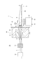
- FIG. 3 is a cross-sectional view showing details of the vicinity of the target included in the neutron capture therapy apparatus of the present embodiment.
- the target 8 is detachably attached to the downstream end of the beam transport path 12 by a target holder 19.
- the target holder 19 includes a flanged short tube 17 and a cooling plate 18.
- the target holder 19 sandwiches and holds the target 8 by the flanged short tube 17 and the cooling plate 18.
- the flanged short tube 17 is fixed to an end portion on the downstream side of the beam transport path 12.
- the target 8 has a plate shape and is integrally formed by, for example, pressing a sintered body.
- the target 8 has a protruding portion 8c and a flange portion 8d.
- the protrusion 8 c protrudes in the irradiation direction of the charged particle beam L.
- the irradiation axis A means an axis through which the beam center of the charged particle beam L passes when the charged particle beam L is irradiated without being deflected.
- the irradiation direction is a direction in which the irradiation axis A extends and the charged particle beam L is irradiated.
- the target 8 according to the present embodiment has a rectangular shape when viewed from the irradiation direction, and has a longitudinal direction D1 (first direction, predetermined direction) and a short direction D2.
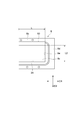
- FIG. 4 is a view of the target 8 as viewed from the opposite side of the irradiation direction.
- FIG. 5 is a view of the target 8 viewed from the short direction D2.
- FIG. 3 is a cross-sectional view of the target 8 as viewed from the longitudinal direction D1.
- the protrusion 8c of the target 8 has a cross-sectional shape that curves so as to protrude convexly toward the beam transport path 12 along the irradiation axis A when viewed from the longitudinal direction D1. Curved means smoothly bent and not linear.
- the protrusion 8c of the target 8 has a shape that is extended so that the cross-sectional shape is continuous along the longitudinal direction D1.
- the protruding portion 8c has an arch shape curved with a radius of curvature that can ensure sufficient strength. Even when the protrusion 8c of the target 8 is cut at any position in the longitudinal direction D1, it has the same cross-sectional shape when viewed from the longitudinal direction D1. However, the shape (size, radius of curvature, etc.) of the protrusion 8c may be different depending on the position in the longitudinal direction D1.
- both end portions in the longitudinal direction D1 of the protruding portion 8c are sealed with the side wall portion 8e.
- the protrusion part 8c has comprised the rectangular shape extended along the longitudinal direction D1.
- the protruding portion 8c may protrude in a range that covers at least the scanning range of the charged particle beam scanning unit 13, that is, a range in which the charged particle beam L is irradiated.
- the protrusion 8c has a front surface 8a and a back surface 8b.
- the surface 8a is a surface of the flanged short tube 17 side. When the charged particle beam L passes through the flanged short tube 17, the surface 8a is irradiated. When the target 8 is irradiated with the charged particle beam L, the target 8 generates a neutron beam N.
- the back surface 8b is a surface in contact with the cooling plate 18 made of cooling water. Neutron beams N generated from the target 8 are emitted from the back surface 8b of the protrusion 8c.
- the back surface 8b may be subjected to an anodizing treatment for corrosion prevention.
- the back surface 8b protrudes so as to follow the protruding shape of the front surface 8a.
- the front surface 8a and the back surface 8b are separated so that the thickness of the protruding portion 8c is substantially constant.
- the thickness of the protrusion 8c is the shortest distance from an arbitrary point on the front surface 8a to the back surface 8b, that is, the plate thickness of the protrusion 8c.
- plate thickness the thickness of the protrusion 8c
- the plate thickness of the protruding portion 8c may be equal to or less than the maximum thickness (predetermined value) through which the charged particle beam L can pass.
- the thickness of the protrusion 8c in the irradiation direction of the charged particle beam L (hereinafter simply referred to as “irradiation thickness”) may be a plate thickness that is equal to or less than the range of the charged particle beam L.
- the protruding amount of the protruding portion 8 c is an amount that can sufficiently secure the structural strength in relation to the plate thickness of the target 8.
- the shape of the protruding portion 8c when viewed from the longitudinal direction D1 is not limited to the above shape as long as the structural strength is established.
- a semi-ellipsoid, a polygonal shape, or the like may be used.
- the protrusion 8c can take various shapes such as an ellipse and an oval when viewed from the irradiation direction.
- the flange portion 8d extends so as to spread over the entire circumference of the protruding portion 8c.
- the flange portion 8d since the protrusion 8c has a rectangular shape extending in the longitudinal direction D1 when viewed from the irradiation direction, the flange portion 8d has a rectangular frame shape extending in the longitudinal direction D1 in accordance with the protrusion 8c. It has the shape of
- the seal part 50 can be arrange
- the flange portion 8 d is attached so as to be sandwiched between the flanged short tube 17 and the cooling plate (cooling portion) 18.
- the cooling plate 18 is made of copper (Cu) or graphite.
- the cooling plate 18 has a main body portion 28 and a pair of overhang portions 29 and 30 provided at opposing positions so as to sandwich the main body portion 28.
- the main body 28 has a front surface 18a and a back surface 18b.
- the main body 28 includes a protrusion 18c and a flange 18d.
- the protrusion 18c is shaped so as to be in contact with the protrusion 8c of the target 8 on the surface 18a side.
- a groove 24 through which cooling water passes is formed in the protrusion 18c on the surface 18a side. That is, the cooling plate 18 is a cooling plate having a cooling passage through which a cooling medium (for example, cooling water) flows so as to be in contact with the target 8.
- a cooling medium for example, cooling water
- the groove 24 constituting the cooling passage of the cooling medium of the cooling plate 18 constitutes a wide space extending in the longitudinal direction D1 and the short direction D2. Further, the groove 24 of the cooling passage has a length L2 in the short direction smaller than the length L1 in the long direction D1. In the present embodiment, the grooves 24 extending in both the longitudinal direction D1 and the short direction D2 are formed. However, the present invention is not limited to this as long as the target 8 can be cooled.
- the flange portion 18d of the cooling plate 18 has a shape such that a part thereof is in contact with the flange portion 8d of the target 8 on the surface 18a side.
- the flange portion 8d of the target 8 is sandwiched and fixed between the flange portion 18d and the flanged short tube 17.
- the lid portion 42 is bolted.
- the lid portion 42 has a shape corresponding to the shapes of the main body portion 28 and the overhang portions 29 and 30.
- the lid portion 42 is attached so as to close the introduction groove 25 and the discharge groove 26.
- the lid portion 42 forms a cooling water introduction path in the introduction groove 25, and forms a cooling water discharge path in the discharge groove 26.
- the cooling plate 18 and the lid portion 42 may be integrally formed.
- the lower overhang portion 29 is formed with an introduction hole 36 communicating with the introduction groove 25. Further, the overhang portion 29 is connected to an upstream pipe 38 laid for introducing cooling water through both flange pipes 37. Further, a discharge hole 39 communicating with the discharge groove 26 is formed in the upper overhanging portion 30. The overhang portion 30 is connected to a downstream pipe 41 laid for discharging cooling water via both flange pipes 40.
- the target 8 includes a first layer 8A and a second layer 8B from the upstream side to the downstream side in the irradiation direction of the charged particle beam L. Further, the hydrogen storage performance of the second layer 8B is higher than that of the first layer 8A. By increasing the hydrogen storage performance of the second layer 8B on the cooled side, even if hydrogen is generated on the back surface side of the target 8, hydrogen can be stored in the second layer 8B.
- beryllium (Be), lithium (Li), tantalum (Ta), or tungsten (W) may be employed as the first layer 8A as described above.
- a material containing Ti may be adopted as the second layer 8B. For example, Ti-6Al-4V may be employed. Since the material has high tensile strength, it contributes to improving the strength of the target 8.
- barber foil (SUS alloy) may be employed as the second layer 8B.
- FIG. 7 is a graph showing the relationship between the thicknesses of the first layer 8A and the second layer 8B and the position of the Bragg peak of the charged particle beam L.
- the position P of the Bragg peak is in the cooling medium on the back side of the target 8. .
- generation of hydrogen in the target 8 can be suppressed.
- the position P of the Bragg peak is the position of the second layer 8B. Therefore, even if hydrogen is generated in the target 8, it can be occluded by the second layer 8B.
- the target 8 has a cross-sectional shape that protrudes along the irradiation axis A when viewed from the longitudinal direction D1 orthogonal to the irradiation axis A of the charged particle beam L. And has a shape that is stretched so that the cross-sectional shape is continuous along the longitudinal direction D1. According to the shape, since the strength of the target 8 can be ensured and thinned, the Bragg peak of the charged particle beam L can be downstream from the target 8 or the Bragg peak in the target can be suppressed (here Then, it becomes easy to position it in the second layer). Therefore, the occurrence of blistering in the target 8 can be suppressed.
- the irradiation area of the neutron beam N can be increased. Furthermore, since the area of the target 8 can be increased without increasing the curvature of the target 8, the strength can be ensured while increasing the area. From the above, the irradiation area of the neutron beam N can be increased while ensuring the strength while suppressing the occurrence of blistering in the target 8. Further, by increasing the area of the target 8, a wide irradiation field can be obtained when the patient is irradiated with the neutron beam N.
- the target 8 includes the first layer 8A and the second layer 8B from the upstream side to the downstream side in the irradiation direction of the charged particle beam L. . Further, the hydrogen storage performance of the second layer 8B is higher than that of the first layer 8A. In this case, even if hydrogen is generated in the target 8, generation of blistering can be suppressed by storing the hydrogen in the second layer 8B having high hydrogen storage performance.
- a cooling plate 18 that cools the target 8 by flowing a cooling medium is provided on the downstream side of the target 8 in the irradiation direction of the charged particle beam L.
- the groove 24 constituting the cooling passage of the cooling medium of the cooling plate 18 extends in the irradiation direction and the short direction D2.
- the cooling passage can be widened, cooling water exists on the back side (downstream side) of the portion irradiated with the charged particle beam L in the target 8, and hydrogen is captured by the cooling water. It is possible to collect and suppress the occurrence of blistering.
- the target 8 is a target that generates a neutron beam N by causing a nuclear reaction by being irradiated with the charged particle beam L.
- the irradiation axis A When viewed from the longitudinal direction D1, the irradiation axis A is It has a cross-sectional shape protruding along the extending direction, and has a shape extended so that the cross-sectional shape continues along the longitudinal direction D1.
- the same actions and effects as those of the neutron capture therapy apparatus 1 described above can be obtained.
- the projecting portion 8 c of the target 8 is projected toward the beam transport path 12, but may be projected to the opposite side of the beam transport path 12.
- the target 8 is composed of the first layer and the second layer, but may be composed of multiple layers. Alternatively, it may be composed of a single layer.
- the longitudinal direction and short direction of the target may be reversed, and the target may be square.
- SYMBOLS 1 Neutron capture therapy apparatus, 8 ... Target, 8A ... 1st layer, 8B ... 2nd layer, 11 ... Accelerator, 18 ... Cooling plate (cooling part), 24 ... Groove (cooling passage), A ... Irradiation axis .
Landscapes
- Engineering & Computer Science (AREA)
- Physics & Mathematics (AREA)
- Health & Medical Sciences (AREA)
- Biomedical Technology (AREA)
- High Energy & Nuclear Physics (AREA)
- Spectroscopy & Molecular Physics (AREA)
- Nuclear Medicine, Radiotherapy & Molecular Imaging (AREA)
- Pathology (AREA)
- Plasma & Fusion (AREA)
- Radiology & Medical Imaging (AREA)
- Life Sciences & Earth Sciences (AREA)
- Animal Behavior & Ethology (AREA)
- General Health & Medical Sciences (AREA)
- Public Health (AREA)
- Veterinary Medicine (AREA)
- General Engineering & Computer Science (AREA)
- Radiation-Therapy Devices (AREA)
- Particle Accelerators (AREA)
Abstract
La présente invention concerne un dispositif de thérapie par capture de neutrons qui est un dispositif de thérapie par capture de neutrons qui émet un rayonnement d'un faisceau de neutrons vers un objet à exposer au rayonnement, et qui comprend : un accélérateur qui accélère des particules chargées et qui émet un faisceau de particules chargées ; une cible qui est amenée à générer un faisceau de neutrons après exposition à un rayonnement par des particules chargées émises par l'accélérateur ; et une unité de placement sur laquelle est placé l'objet à exposer au rayonnement, qui est destiné à être exposé à un rayonnement par le faisceau de neutrons. Dans une vue selon une première direction perpendiculaire à l'axe de rayonnement du faisceau de particules chargées, la cible présente une forme transversale qui fait saillie ou est en retrait le long de l'axe de rayonnement. La cible présente une forme obtenue par extension de la forme transversale en continu dans la première direction.
Applications Claiming Priority (2)
| Application Number | Priority Date | Filing Date | Title |
|---|---|---|---|
| JP2016-035954 | 2016-02-26 | ||
| JP2016035954A JP2019068870A (ja) | 2016-02-26 | 2016-02-26 | 中性子捕捉療法装置、及び中性子捕捉療法用ターゲット |
Publications (1)
| Publication Number | Publication Date |
|---|---|
| WO2017146205A1 true WO2017146205A1 (fr) | 2017-08-31 |
Family
ID=59685321
Family Applications (1)
| Application Number | Title | Priority Date | Filing Date |
|---|---|---|---|
| PCT/JP2017/007082 Ceased WO2017146205A1 (fr) | 2016-02-26 | 2017-02-24 | Dispositif de thérapie par capture de neutrons, et cible pour thérapie par capture de neutrons |
Country Status (2)
| Country | Link |
|---|---|
| JP (1) | JP2019068870A (fr) |
| WO (1) | WO2017146205A1 (fr) |
Cited By (8)
| Publication number | Priority date | Publication date | Assignee | Title |
|---|---|---|---|---|
| CN108550411A (zh) * | 2018-05-29 | 2018-09-18 | 河南太粒科技有限公司 | 一种镶嵌式靶结构 |
| CN109464750A (zh) * | 2017-09-07 | 2019-03-15 | 南京中硼联康医疗科技有限公司 | 中子捕获治疗系统 |
| CN109464751A (zh) * | 2017-09-07 | 2019-03-15 | 南京中硼联康医疗科技有限公司 | 中子捕获治疗系统 |
| WO2019114307A1 (fr) * | 2017-12-15 | 2019-06-20 | 南京中硼联康医疗科技有限公司 | Système de thérapie par capture de neutrons |
| CN111212510A (zh) * | 2020-02-29 | 2020-05-29 | 北京惠康得医疗科技研究院有限公司 | 适应于bnct系统的复合中子靶 |
| CN111954362A (zh) * | 2019-05-16 | 2020-11-17 | 禾荣科技股份有限公司 | 散热结构及使用其的中子束产生装置 |
| CN115623652A (zh) * | 2021-07-16 | 2023-01-17 | 中硼(厦门)医疗器械有限公司 | 用于粒子束产生装置的靶材 |
| TWI838216B (zh) * | 2023-04-12 | 2024-04-01 | 禾榮科技股份有限公司 | 散熱結構及使用其的中子束產生裝置 |
Families Citing this family (1)
| Publication number | Priority date | Publication date | Assignee | Title |
|---|---|---|---|---|
| JP7430057B2 (ja) * | 2019-12-25 | 2024-02-09 | 住友重機械工業株式会社 | 校正装置、治療計画装置及び校正方法 |
Citations (6)
| Publication number | Priority date | Publication date | Assignee | Title |
|---|---|---|---|---|
| JPH11258399A (ja) * | 1998-03-13 | 1999-09-24 | Hitachi Ltd | 液体ターゲット及び中性子発生設備 |
| JP2000180600A (ja) * | 1998-12-11 | 2000-06-30 | Hitachi Ltd | 固体ターゲット及び中性子発生装置 |
| WO2008025737A1 (fr) * | 2006-08-29 | 2008-03-06 | Ion Beam Applications S.A. | Dispositif générateur de neutrons pour boroneutrothérapie |
| JP2010203882A (ja) * | 2009-03-03 | 2010-09-16 | Sumitomo Heavy Ind Ltd | ターゲット及びそれを備えるターゲット装置 |
| JP2011033512A (ja) * | 2009-08-04 | 2011-02-17 | Mitsubishi Electric Corp | 中性子発生源用ターゲット |
| JP2015095365A (ja) * | 2013-11-12 | 2015-05-18 | 田中貴金属工業株式会社 | 中性子発生用ターゲット |
-
2016
- 2016-02-26 JP JP2016035954A patent/JP2019068870A/ja active Pending
-
2017
- 2017-02-24 WO PCT/JP2017/007082 patent/WO2017146205A1/fr not_active Ceased
Patent Citations (6)
| Publication number | Priority date | Publication date | Assignee | Title |
|---|---|---|---|---|
| JPH11258399A (ja) * | 1998-03-13 | 1999-09-24 | Hitachi Ltd | 液体ターゲット及び中性子発生設備 |
| JP2000180600A (ja) * | 1998-12-11 | 2000-06-30 | Hitachi Ltd | 固体ターゲット及び中性子発生装置 |
| WO2008025737A1 (fr) * | 2006-08-29 | 2008-03-06 | Ion Beam Applications S.A. | Dispositif générateur de neutrons pour boroneutrothérapie |
| JP2010203882A (ja) * | 2009-03-03 | 2010-09-16 | Sumitomo Heavy Ind Ltd | ターゲット及びそれを備えるターゲット装置 |
| JP2011033512A (ja) * | 2009-08-04 | 2011-02-17 | Mitsubishi Electric Corp | 中性子発生源用ターゲット |
| JP2015095365A (ja) * | 2013-11-12 | 2015-05-18 | 田中貴金属工業株式会社 | 中性子発生用ターゲット |
Cited By (13)
| Publication number | Priority date | Publication date | Assignee | Title |
|---|---|---|---|---|
| CN109464750B (zh) * | 2017-09-07 | 2024-01-12 | 南京中硼联康医疗科技有限公司 | 中子捕获治疗系统 |
| CN109464750A (zh) * | 2017-09-07 | 2019-03-15 | 南京中硼联康医疗科技有限公司 | 中子捕获治疗系统 |
| CN109464751A (zh) * | 2017-09-07 | 2019-03-15 | 南京中硼联康医疗科技有限公司 | 中子捕获治疗系统 |
| CN109464751B (zh) * | 2017-09-07 | 2024-03-22 | 南京中硼联康医疗科技有限公司 | 中子捕获治疗系统 |
| WO2019114307A1 (fr) * | 2017-12-15 | 2019-06-20 | 南京中硼联康医疗科技有限公司 | Système de thérapie par capture de neutrons |
| US11266859B2 (en) | 2017-12-15 | 2022-03-08 | Neuboron Medtech Ltd. | Neutron capture therapy system |
| CN108550411A (zh) * | 2018-05-29 | 2018-09-18 | 河南太粒科技有限公司 | 一种镶嵌式靶结构 |
| CN111954362A (zh) * | 2019-05-16 | 2020-11-17 | 禾荣科技股份有限公司 | 散热结构及使用其的中子束产生装置 |
| US11521763B2 (en) * | 2019-05-16 | 2022-12-06 | Heron Neutron Medical Corp. | Heat dissipation structure and neutron beam generating device using the same |
| CN111212510A (zh) * | 2020-02-29 | 2020-05-29 | 北京惠康得医疗科技研究院有限公司 | 适应于bnct系统的复合中子靶 |
| CN115623652A (zh) * | 2021-07-16 | 2023-01-17 | 中硼(厦门)医疗器械有限公司 | 用于粒子束产生装置的靶材 |
| TWI838216B (zh) * | 2023-04-12 | 2024-04-01 | 禾榮科技股份有限公司 | 散熱結構及使用其的中子束產生裝置 |
| JP7618282B2 (ja) | 2023-04-12 | 2025-01-21 | 禾榮科技股▲フン▼有限公司 | 放熱構造及びそれを用いた中性子ビーム発生装置 |
Also Published As
| Publication number | Publication date |
|---|---|
| JP2019068870A (ja) | 2019-05-09 |
Similar Documents
| Publication | Publication Date | Title |
|---|---|---|
| WO2017146205A1 (fr) | Dispositif de thérapie par capture de neutrons, et cible pour thérapie par capture de neutrons | |
| JP6144175B2 (ja) | 中性子捕捉療法装置 | |
| CN108156742B (zh) | 中子束源产生器及其滤屏 | |
| JP5054335B2 (ja) | ホウ素中性子捕捉療法用の医療装置 | |
| JP2022091813A (ja) | 中性子捕捉治療システムおよび粒子線発生装置用のターゲット | |
| JP2023002608A (ja) | 中性子捕捉療法用のビーム成形体 | |
| JP2023078466A (ja) | 中性子捕捉療法システム | |
| TWI686225B (zh) | 中子捕獲治療系統 | |
| JP5850362B2 (ja) | 中性子線照射装置および当該装置の作動方法 | |
| JP7668910B2 (ja) | 中性子捕捉療法システム | |
| JP2018161449A (ja) | 中性子減速照射装置及び延長コリメータ | |
| JP2007242422A (ja) | 中性子発生装置及び中性子照射システム | |
| JP6257994B2 (ja) | 中性子発生装置及び医療用加速器システム | |
| CN110650777B (zh) | 中子捕捉疗法系统 | |
| KR101839369B1 (ko) | 붕소중성자포획치료(bnct) 시설 | |
| JP2017173283A (ja) | 中性子減速照射装置 | |
| CN213159020U (zh) | 中子捕获治疗系统 | |
| JP7072196B1 (ja) | Bnctにおける低エネルギーの荷電粒子線輸送システム及び荷電粒子線輸送方法 | |
| CN111686376A (zh) | 中子捕获治疗系统 | |
| KR102274044B1 (ko) | 환자 치료위치를 고려한 감속집합체 | |
| CN210302074U (zh) | 中子捕获治疗系统 | |
| TWI632933B (zh) | Neutron capture therapy system and target for particle beam generating device | |
| WO2023112935A1 (fr) | Cible pour dispositif de génération de neutrons et son procédé de production | |
| US20250018225A1 (en) | Neutron capture therapy device and collimator | |
| JP7821162B2 (ja) | 中性子線発生装置、及び中性子線治療設備 |
Legal Events
| Date | Code | Title | Description |
|---|---|---|---|
| NENP | Non-entry into the national phase |
Ref country code: DE |
|
| 121 | Ep: the epo has been informed by wipo that ep was designated in this application |
Ref document number: 17756639 Country of ref document: EP Kind code of ref document: A1 |
|
| 122 | Ep: pct application non-entry in european phase |
Ref document number: 17756639 Country of ref document: EP Kind code of ref document: A1 |
|
| NENP | Non-entry into the national phase |
Ref country code: JP |