WO2017146205A1 - 中性子捕捉療法装置、及び中性子捕捉療法用ターゲット - Google Patents
中性子捕捉療法装置、及び中性子捕捉療法用ターゲット Download PDFInfo
- Publication number
- WO2017146205A1 WO2017146205A1 PCT/JP2017/007082 JP2017007082W WO2017146205A1 WO 2017146205 A1 WO2017146205 A1 WO 2017146205A1 JP 2017007082 W JP2017007082 W JP 2017007082W WO 2017146205 A1 WO2017146205 A1 WO 2017146205A1
- Authority
- WO
- WIPO (PCT)
- Prior art keywords
- target
- charged particle
- neutron
- capture therapy
- particle beam
- Prior art date
- Legal status (The legal status is an assumption and is not a legal conclusion. Google has not performed a legal analysis and makes no representation as to the accuracy of the status listed.)
- Ceased
Links
Images


Classifications
-
- A—HUMAN NECESSITIES
- A61—MEDICAL OR VETERINARY SCIENCE; HYGIENE
- A61N—ELECTROTHERAPY; MAGNETOTHERAPY; RADIATION THERAPY; ULTRASOUND THERAPY
- A61N5/00—Radiation therapy
- A61N5/10—X-ray therapy; Gamma-ray therapy; Particle-irradiation therapy
-
- G—PHYSICS
- G21—NUCLEAR PHYSICS; NUCLEAR ENGINEERING
- G21K—HANDLING OF PARTICLES OR IONISING RADIATION NOT OTHERWISE PROVIDED FOR; IRRADIATION DEVICES; GAMMA RAY OR X-RAY MICROSCOPES
- G21K5/00—Irradiation devices
- G21K5/08—Holders for targets or for other objects to be irradiated
-
- H—ELECTRICITY
- H05—ELECTRIC TECHNIQUES NOT OTHERWISE PROVIDED FOR
- H05H—PLASMA TECHNIQUE; PRODUCTION OF ACCELERATED ELECTRICALLY-CHARGED PARTICLES OR OF NEUTRONS; PRODUCTION OR ACCELERATION OF NEUTRAL MOLECULAR OR ATOMIC BEAMS
- H05H3/00—Production or acceleration of neutral particle beams, e.g. molecular or atomic beams
- H05H3/06—Generating neutron beams
Definitions
- the present invention relates to a neutron capture therapy apparatus and a target for neutron capture therapy.
- boron neutron capture therapy using a boron compound is known as a neutron capture therapy for irradiating a neutron beam to kill cancer cells.
- neutrons are irradiated to boron that has been previously taken up by cancer cells, and the cancer cells are selectively destroyed by scattering of heavy charged particles generated thereby.
- Patent Document 1 discloses an apparatus having an accelerator that emits a charged particle beam and a target that generates a neutron beam by being irradiated with the charged particle beam.
- the target of this neutron capture therapy apparatus ensures strength by protruding in a hemispherical shape along the irradiation axis of the charged particle beam. Since it is possible to reduce the thickness by using a shape that can ensure strength, blistering due to hydrogen retention is suppressed by positioning the Bragg peak of the charged particle beam in the cooling section downstream of the target. is doing.
- this invention aims at providing the neutron capture therapy apparatus and the target for neutron capture therapy which can enlarge the irradiation area of a neutron beam, ensuring intensity
- a neutron capture therapy apparatus is a neutron capture therapy apparatus that irradiates an irradiated object with a neutron beam, and accelerates charged particles to emit a charged particle beam And a target that generates a neutron beam by being irradiated with a charged particle beam emitted from an accelerator, and a placement unit on which an irradiated object that is irradiated with the neutron beam is placed, and the target is charged
- viewed from a first direction orthogonal to the particle beam irradiation axis it has a cross-sectional shape protruding or recessed along the irradiation axis, and stretched so that the cross-sectional shape continues along the first direction. The shape is made.
- the target has a cross-sectional shape protruding or recessed along the irradiation axis when viewed from a first direction orthogonal to the irradiation axis of the charged particle beam. And has a shape that is stretched so that the cross-sectional shape is continuous along the first direction. According to the shape, since the strength of the target can be ensured and thinned, it becomes easy to position the Bragg peak of the charged particle beam downstream from the target or at a place where the Bragg peak in the target can be suppressed. . Therefore, the occurrence of blistering in the target can be suppressed.
- the irradiation area of a neutron beam can be enlarged. Further, since the area of the target can be increased without increasing the curvature of the target, the strength can be ensured while increasing the area. From the above, the irradiation area of the neutron beam can be increased while ensuring the strength while suppressing the occurrence of blistering in the target.
- the target includes a first layer and a second layer in order from the upstream side to the downstream side in the irradiation direction of the charged particle beam, and the hydrogen storage performance of the second layer is It may be higher than the first layer. In this case, even if hydrogen is generated in the target, generation of blistering can be suppressed by storing hydrogen in the second layer having high hydrogen storage performance.
- a cooling unit that cools the target by flowing a cooling medium is provided on the downstream side of the target, and the cooling passage of the cooling medium of the cooling unit extends in the first direction. And extending in the irradiation direction and the second direction orthogonal to the first direction, and the length in the first direction is larger than the length in the second direction.
- the cooling passage can be widened, cooling water exists on the back side (downstream side) of the portion irradiated with the charged particle beam on the target, and hydrogen is collected by the cooling water.
- the occurrence of blistering can be suppressed.
- the neutron capture therapy target is a neutron capture therapy target that generates a neutron beam by being irradiated with a charged particle beam.
- the target When viewed from a predetermined direction, the target is along a direction orthogonal to the predetermined direction. It has a cross-sectional shape that protrudes or is recessed, and has a shape that is extended so that the cross-sectional shape continues along a predetermined direction.
- the present invention it is possible to increase the irradiation area of the neutron beam while ensuring the strength while suppressing the occurrence of blistering in the target.
- FIG. 1 It is a figure which shows arrangement
- FIGS. 1 and 2 the neutron capture therapy apparatus 1 for cancer treatment with boron neutron capture therapy, patients boron (10 B) has been administered (irradiation object) boron S is accumulated A device that treats cancer by irradiating a site with neutrons.
- the neutron capture therapy apparatus 1 has an irradiation chamber 2 that irradiates a patient S restrained by a treatment table 3 with a neutron beam N to treat the patient S with cancer.
- the neutron capture therapy apparatus 1 includes a neutron beam generator 10 that generates a neutron beam N for treatment, and a neutron beam irradiator that irradiates the patient S restrained by the treatment table 3 in the irradiation chamber 2 with the neutron beam N. 20.
- a passage and a door 45 may be provided in order for a patient, an operator, etc. to pass.
- the neutron beam generation unit 10 scans the charged particle beam L, an accelerator 11 that accelerates charged particles and emits the charged particle beam L, a beam transport path 12 that transports the charged particle beam L emitted by the accelerator 11, and the charged particle beam L.
- a charged particle beam scanning unit 13 that controls the irradiation position of the charged particle beam L with respect to the target 8, a target 8 that generates a neutron beam N by causing a nuclear reaction when irradiated with the charged particle beam L, and a charged particle beam
- a current monitor 16 for measuring the current of L.
- the accelerator 11 and the beam transport path 12 are disposed in a charged particle beam generation chamber 14 having a substantially rectangular shape, and the charged particle beam generation chamber 14 is a space covered with a concrete shielding wall W. .
- the charged particle beam generation chamber 14 may be provided with a passage and a door 46 through which an operator for maintenance passes.
- the charged particle beam generation chamber 14 is not limited to a substantially rectangular shape, and may have another shape. For example, when the path from the accelerator to the target is L-shaped, the charged particle beam generation chamber 14 may also be L-shaped.
- the charged particle beam scanning unit 13 controls the irradiation position of the charged particle beam L with respect to the target 8, for example, and the current monitor 16 measures the current of the charged particle beam L irradiated to the target 8.
- the accelerator 11 generates charged particle beams L such as proton beams by accelerating charged particles such as protons.
- a cyclotron is employed as the accelerator 11.
- the accelerator 11 may be another accelerator such as a synchrotron, a synchrocyclotron, or a linac instead of the cyclotron.
- the beam transport path 12 includes a beam adjusting unit 15 that adjusts the charged particle beam L.
- the beam adjusting unit 15 includes a horizontal steering electromagnet and a horizontal vertical electromagnet that adjust the axis of the charged particle beam L, a quadrupole electromagnet that suppresses the divergence of the charged particle beam L, and a four-way that shapes the charged particle beam L. Has slits and the like.
- the beam transport path 12 only needs to have a function of transporting the charged particle beam L, and the beam adjustment unit 15 may not be provided.
- the charged particle beam L transported by the beam transport path 12 is irradiated to the target 8 by controlling the irradiation position by the charged particle beam scanning unit 13.
- the charged particle beam scanning unit 13 may be omitted, and the charged particle beam L may always be irradiated to the same portion of the target 8.
- the target 8 generates a neutron beam N when irradiated with the charged particle beam L.
- the target 8 is made of, for example, beryllium (Be), lithium (Li), tantalum (Ta), or tungsten (W), and has a plate shape (however, details of the material of the target 8 will be described later). To do).
- the neutron beam N generated by the target 8 is irradiated toward the patient S in the irradiation chamber 2 by the neutron beam irradiation unit 20.
- the neutron beam irradiation unit 20 includes a moderator 21 that decelerates the neutron beam N emitted from the target 8, and a shield 22 that shields radiation such as neutron beam N and gamma rays from being emitted to the outside.
- the moderator 21 and the shield 22 constitute a moderator.
- the moderator 21 has a laminated structure made of a plurality of different materials, for example, and the material of the moderator 21 is appropriately selected according to various conditions such as the energy of the charged particle beam L. Specifically, for example, when the output from the accelerator 11 is a proton beam of 30 MeV and a beryllium target is used as the target 8, the material of the moderator 21 can be lead, iron, aluminum, or calcium fluoride.
- the shield 22 is provided so as to surround the moderator 21, and has a function of shielding the neutron beam N and radiation such as gamma rays generated with the generation of the neutron beam N from being emitted to the outside of the shield 22.
- the shield 22 may be at least partially embedded in the wall W1 separating the charged particle beam generation chamber 14 and the irradiation chamber 2 or may not be embedded.
- a wall body 23 that forms a part of the side wall surface of the irradiation chamber 2 is provided between the irradiation chamber 2 and the shield 22.
- the wall body 23 is provided with a collimator mounting portion 23a serving as an output port of the neutron beam N.
- a collimator 31 for defining an irradiation field of the neutron beam N is fixed to the collimator mounting portion 23a. In addition, you may attach the collimator 31 to the treatment table 3 mentioned later, without providing the collimator attaching part 23a in the wall body 23.
- FIG. 1 A collimator 31 for defining an irradiation field of the neutron beam N is fixed to the collimator mounting portion 23a. In addition, you may attach the collimator 31 to the treatment table 3 mentioned later, without providing the collimator attaching part 23a in the wall body 23.
- the target 8 is irradiated with the charged particle beam L, and the target 8 generates the neutron beam N along with this.
- the neutron beam N generated by the target 8 is decelerated while passing through the moderator 21, and the neutron beam N emitted from the moderator 21 passes through the collimator 31 to the patient S on the treatment table 3. Irradiated.
- the neutron beam N a thermal neutron beam or an epithermal neutron beam having relatively low energy can be used.
- the treatment table 3 functions as a mounting table used in neutron capture therapy, and can be moved from the preparation room (not shown) to the irradiation room 2 with the patient S mounted thereon.
- the treatment table 3 includes a base portion 32 that constitutes the base of the treatment table 3, a caster 33 that enables the base portion 32 to move on the floor surface, a top plate 34 on which the patient S is placed, and a top plate 34. And a drive unit 35 for moving the base plate 32 relative to the base unit 32. Note that the base portion 32 may be fixed to the floor without using the casters 33.
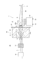
- FIG. 3 is a cross-sectional view showing details of the vicinity of the target included in the neutron capture therapy apparatus of the present embodiment.
- the target 8 is detachably attached to the downstream end of the beam transport path 12 by a target holder 19.
- the target holder 19 includes a flanged short tube 17 and a cooling plate 18.
- the target holder 19 sandwiches and holds the target 8 by the flanged short tube 17 and the cooling plate 18.
- the flanged short tube 17 is fixed to an end portion on the downstream side of the beam transport path 12.
- the target 8 has a plate shape and is integrally formed by, for example, pressing a sintered body.
- the target 8 has a protruding portion 8c and a flange portion 8d.
- the protrusion 8 c protrudes in the irradiation direction of the charged particle beam L.
- the irradiation axis A means an axis through which the beam center of the charged particle beam L passes when the charged particle beam L is irradiated without being deflected.
- the irradiation direction is a direction in which the irradiation axis A extends and the charged particle beam L is irradiated.
- the target 8 according to the present embodiment has a rectangular shape when viewed from the irradiation direction, and has a longitudinal direction D1 (first direction, predetermined direction) and a short direction D2.
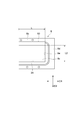
- FIG. 4 is a view of the target 8 as viewed from the opposite side of the irradiation direction.
- FIG. 5 is a view of the target 8 viewed from the short direction D2.
- FIG. 3 is a cross-sectional view of the target 8 as viewed from the longitudinal direction D1.
- the protrusion 8c of the target 8 has a cross-sectional shape that curves so as to protrude convexly toward the beam transport path 12 along the irradiation axis A when viewed from the longitudinal direction D1. Curved means smoothly bent and not linear.
- the protrusion 8c of the target 8 has a shape that is extended so that the cross-sectional shape is continuous along the longitudinal direction D1.
- the protruding portion 8c has an arch shape curved with a radius of curvature that can ensure sufficient strength. Even when the protrusion 8c of the target 8 is cut at any position in the longitudinal direction D1, it has the same cross-sectional shape when viewed from the longitudinal direction D1. However, the shape (size, radius of curvature, etc.) of the protrusion 8c may be different depending on the position in the longitudinal direction D1.
- both end portions in the longitudinal direction D1 of the protruding portion 8c are sealed with the side wall portion 8e.
- the protrusion part 8c has comprised the rectangular shape extended along the longitudinal direction D1.
- the protruding portion 8c may protrude in a range that covers at least the scanning range of the charged particle beam scanning unit 13, that is, a range in which the charged particle beam L is irradiated.
- the protrusion 8c has a front surface 8a and a back surface 8b.
- the surface 8a is a surface of the flanged short tube 17 side. When the charged particle beam L passes through the flanged short tube 17, the surface 8a is irradiated. When the target 8 is irradiated with the charged particle beam L, the target 8 generates a neutron beam N.
- the back surface 8b is a surface in contact with the cooling plate 18 made of cooling water. Neutron beams N generated from the target 8 are emitted from the back surface 8b of the protrusion 8c.
- the back surface 8b may be subjected to an anodizing treatment for corrosion prevention.
- the back surface 8b protrudes so as to follow the protruding shape of the front surface 8a.
- the front surface 8a and the back surface 8b are separated so that the thickness of the protruding portion 8c is substantially constant.
- the thickness of the protrusion 8c is the shortest distance from an arbitrary point on the front surface 8a to the back surface 8b, that is, the plate thickness of the protrusion 8c.
- plate thickness the thickness of the protrusion 8c
- the plate thickness of the protruding portion 8c may be equal to or less than the maximum thickness (predetermined value) through which the charged particle beam L can pass.
- the thickness of the protrusion 8c in the irradiation direction of the charged particle beam L (hereinafter simply referred to as “irradiation thickness”) may be a plate thickness that is equal to or less than the range of the charged particle beam L.
- the protruding amount of the protruding portion 8 c is an amount that can sufficiently secure the structural strength in relation to the plate thickness of the target 8.
- the shape of the protruding portion 8c when viewed from the longitudinal direction D1 is not limited to the above shape as long as the structural strength is established.
- a semi-ellipsoid, a polygonal shape, or the like may be used.
- the protrusion 8c can take various shapes such as an ellipse and an oval when viewed from the irradiation direction.
- the flange portion 8d extends so as to spread over the entire circumference of the protruding portion 8c.
- the flange portion 8d since the protrusion 8c has a rectangular shape extending in the longitudinal direction D1 when viewed from the irradiation direction, the flange portion 8d has a rectangular frame shape extending in the longitudinal direction D1 in accordance with the protrusion 8c. It has the shape of
- the seal part 50 can be arrange
- the flange portion 8 d is attached so as to be sandwiched between the flanged short tube 17 and the cooling plate (cooling portion) 18.
- the cooling plate 18 is made of copper (Cu) or graphite.
- the cooling plate 18 has a main body portion 28 and a pair of overhang portions 29 and 30 provided at opposing positions so as to sandwich the main body portion 28.
- the main body 28 has a front surface 18a and a back surface 18b.
- the main body 28 includes a protrusion 18c and a flange 18d.
- the protrusion 18c is shaped so as to be in contact with the protrusion 8c of the target 8 on the surface 18a side.
- a groove 24 through which cooling water passes is formed in the protrusion 18c on the surface 18a side. That is, the cooling plate 18 is a cooling plate having a cooling passage through which a cooling medium (for example, cooling water) flows so as to be in contact with the target 8.
- a cooling medium for example, cooling water
- the groove 24 constituting the cooling passage of the cooling medium of the cooling plate 18 constitutes a wide space extending in the longitudinal direction D1 and the short direction D2. Further, the groove 24 of the cooling passage has a length L2 in the short direction smaller than the length L1 in the long direction D1. In the present embodiment, the grooves 24 extending in both the longitudinal direction D1 and the short direction D2 are formed. However, the present invention is not limited to this as long as the target 8 can be cooled.
- the flange portion 18d of the cooling plate 18 has a shape such that a part thereof is in contact with the flange portion 8d of the target 8 on the surface 18a side.
- the flange portion 8d of the target 8 is sandwiched and fixed between the flange portion 18d and the flanged short tube 17.
- the lid portion 42 is bolted.
- the lid portion 42 has a shape corresponding to the shapes of the main body portion 28 and the overhang portions 29 and 30.
- the lid portion 42 is attached so as to close the introduction groove 25 and the discharge groove 26.
- the lid portion 42 forms a cooling water introduction path in the introduction groove 25, and forms a cooling water discharge path in the discharge groove 26.
- the cooling plate 18 and the lid portion 42 may be integrally formed.
- the lower overhang portion 29 is formed with an introduction hole 36 communicating with the introduction groove 25. Further, the overhang portion 29 is connected to an upstream pipe 38 laid for introducing cooling water through both flange pipes 37. Further, a discharge hole 39 communicating with the discharge groove 26 is formed in the upper overhanging portion 30. The overhang portion 30 is connected to a downstream pipe 41 laid for discharging cooling water via both flange pipes 40.
- the target 8 includes a first layer 8A and a second layer 8B from the upstream side to the downstream side in the irradiation direction of the charged particle beam L. Further, the hydrogen storage performance of the second layer 8B is higher than that of the first layer 8A. By increasing the hydrogen storage performance of the second layer 8B on the cooled side, even if hydrogen is generated on the back surface side of the target 8, hydrogen can be stored in the second layer 8B.
- beryllium (Be), lithium (Li), tantalum (Ta), or tungsten (W) may be employed as the first layer 8A as described above.
- a material containing Ti may be adopted as the second layer 8B. For example, Ti-6Al-4V may be employed. Since the material has high tensile strength, it contributes to improving the strength of the target 8.
- barber foil (SUS alloy) may be employed as the second layer 8B.
- FIG. 7 is a graph showing the relationship between the thicknesses of the first layer 8A and the second layer 8B and the position of the Bragg peak of the charged particle beam L.
- the position P of the Bragg peak is in the cooling medium on the back side of the target 8. .
- generation of hydrogen in the target 8 can be suppressed.
- the position P of the Bragg peak is the position of the second layer 8B. Therefore, even if hydrogen is generated in the target 8, it can be occluded by the second layer 8B.
- the target 8 has a cross-sectional shape that protrudes along the irradiation axis A when viewed from the longitudinal direction D1 orthogonal to the irradiation axis A of the charged particle beam L. And has a shape that is stretched so that the cross-sectional shape is continuous along the longitudinal direction D1. According to the shape, since the strength of the target 8 can be ensured and thinned, the Bragg peak of the charged particle beam L can be downstream from the target 8 or the Bragg peak in the target can be suppressed (here Then, it becomes easy to position it in the second layer). Therefore, the occurrence of blistering in the target 8 can be suppressed.
- the irradiation area of the neutron beam N can be increased. Furthermore, since the area of the target 8 can be increased without increasing the curvature of the target 8, the strength can be ensured while increasing the area. From the above, the irradiation area of the neutron beam N can be increased while ensuring the strength while suppressing the occurrence of blistering in the target 8. Further, by increasing the area of the target 8, a wide irradiation field can be obtained when the patient is irradiated with the neutron beam N.
- the target 8 includes the first layer 8A and the second layer 8B from the upstream side to the downstream side in the irradiation direction of the charged particle beam L. . Further, the hydrogen storage performance of the second layer 8B is higher than that of the first layer 8A. In this case, even if hydrogen is generated in the target 8, generation of blistering can be suppressed by storing the hydrogen in the second layer 8B having high hydrogen storage performance.
- a cooling plate 18 that cools the target 8 by flowing a cooling medium is provided on the downstream side of the target 8 in the irradiation direction of the charged particle beam L.
- the groove 24 constituting the cooling passage of the cooling medium of the cooling plate 18 extends in the irradiation direction and the short direction D2.
- the cooling passage can be widened, cooling water exists on the back side (downstream side) of the portion irradiated with the charged particle beam L in the target 8, and hydrogen is captured by the cooling water. It is possible to collect and suppress the occurrence of blistering.
- the target 8 is a target that generates a neutron beam N by causing a nuclear reaction by being irradiated with the charged particle beam L.
- the irradiation axis A When viewed from the longitudinal direction D1, the irradiation axis A is It has a cross-sectional shape protruding along the extending direction, and has a shape extended so that the cross-sectional shape continues along the longitudinal direction D1.
- the same actions and effects as those of the neutron capture therapy apparatus 1 described above can be obtained.
- the projecting portion 8 c of the target 8 is projected toward the beam transport path 12, but may be projected to the opposite side of the beam transport path 12.
- the target 8 is composed of the first layer and the second layer, but may be composed of multiple layers. Alternatively, it may be composed of a single layer.
- the longitudinal direction and short direction of the target may be reversed, and the target may be square.
- SYMBOLS 1 Neutron capture therapy apparatus, 8 ... Target, 8A ... 1st layer, 8B ... 2nd layer, 11 ... Accelerator, 18 ... Cooling plate (cooling part), 24 ... Groove (cooling passage), A ... Irradiation axis .
Landscapes
- Engineering & Computer Science (AREA)
- Physics & Mathematics (AREA)
- Health & Medical Sciences (AREA)
- Biomedical Technology (AREA)
- High Energy & Nuclear Physics (AREA)
- Spectroscopy & Molecular Physics (AREA)
- Nuclear Medicine, Radiotherapy & Molecular Imaging (AREA)
- Pathology (AREA)
- Plasma & Fusion (AREA)
- Radiology & Medical Imaging (AREA)
- Life Sciences & Earth Sciences (AREA)
- Animal Behavior & Ethology (AREA)
- General Health & Medical Sciences (AREA)
- Public Health (AREA)
- Veterinary Medicine (AREA)
- General Engineering & Computer Science (AREA)
- Radiation-Therapy Devices (AREA)
- Particle Accelerators (AREA)
Abstract
中性子捕捉療法装置は、被照射体へ中性子線を照射する中性子捕捉療法装置であって、荷電粒子を加速して荷電粒子線を出射する加速器と、加速器から出射された荷電粒子線が照射されることで中性子線を発生させるターゲットと、中性子線が照射される被照射体が載置される載置部と、を備え、ターゲットは、荷電粒子線の照射軸と直交する第1の方向から見た場合に、照射軸に沿って突出又は凹んだ断面形状を有しており、第1の方向に沿って断面形状が連続するように延伸した形状をなしている。
Description
本発明は、中性子捕捉療法装置、及び中性子捕捉療法用ターゲットに関する。
従来、中性子線を照射してがん細胞を死滅させる中性子捕捉療法として、ホウ素化合物を用いたホウ素中性子捕捉療法(BNCT:Boron Neutron Capture Therapy)が知られている。ホウ素中性子捕捉療法では、がん細胞に予め取り込ませておいたホウ素に中性子線を照射し、これにより生じる重荷電粒子の飛散によってがん細胞を選択的に破壊する。
このような中性子捕捉療法で用いられる装置として、例えば、特許文献1には、荷電粒子線を出射する加速器と、荷電粒子線が照射されることで中性子線を発生させるターゲットと、を有する装置が記載されている。この中性子捕捉療法装置のターゲットは、荷電粒子線の照射軸に沿って半球状に突出することで、強度を確保している。このように強度を確保できる形状とすることで薄くすることが可能となるため、荷電粒子線のブラッグピークをターゲットよりも下流側の冷却部に位置させることで、水素の滞留によるブリスタリングを抑制している。
ここで、被照射体に対して広く中性子線を照射するためにターゲットの面積を広くすることが求められている。しかしながら、上述のターゲットは、半球状の形状を有しているため、面積を大きくしながら強度を確保することが困難な場合があった。
そこで本発明は、ターゲット内でのブリスタリングの発生を抑制しつつ、強度を確保しながら中性子線の照射面積を大きくできる中性子捕捉療法装置、及び中性子捕捉療法用ターゲットを提供することを目的とする。
上記課題を解決するため、本発明の一形態に係る中性子捕捉療法装置は、被照射体へ中性子線を照射する中性子捕捉療法装置であって、荷電粒子を加速して荷電粒子線を出射する加速器と、加速器から出射された荷電粒子線が照射されることで中性子線を発生させるターゲットと、中性子線が照射される被照射体が載置される載置部と、を備え、ターゲットは、荷電粒子線の照射軸と直交する第1の方向から見た場合に、照射軸に沿って突出又は凹んだ断面形状を有しており、第1の方向に沿って断面形状が連続するように延伸した形状をなしている。
本発明の一形態に係る中性子捕捉療法装置において、ターゲットは、荷電粒子線の照射軸と直交する第1の方向から見た場合に、照射軸に沿って突出又は凹んだ断面形状を有しており、第1の方向に沿って断面形状が連続するように延伸した形状をなしている。当該形状によれば、ターゲットの強度を確保しつつも薄くすることができるため、荷電粒子線のブラッグピークをターゲットよりも下流側へ、またはターゲット中におけるブラッグピークを抑制できる箇所に位置させ易くなる。従って、ターゲット内でのブリスタリングの発生を抑制できる。また、ターゲットの面積を増やすことができるため、中性子線の照射面積を大きくすることができる。更に、ターゲットの曲率を大きくすることなくターゲットの面積を増やすことができるので、面積を大きくする一方で強度も確保することができる。以上より、ターゲット内でのブリスタリングの発生を抑制しつつ、強度を確保しながら中性子線の照射面積を大きくできる。
また、中性子捕捉療法装置において、ターゲットは、荷電粒子線の照射方向における上流側から下流側へ向かって順に第1の層、及び第2の層を備え、第2の層の水素吸蔵性能は、第1の層に比して高くてよい。この場合、ターゲット内で水素が発生したとしても、水素吸蔵性能の高い第2の層で水素を吸蔵することで、ブリスタリングの発生を抑制できる。
また、中性子捕捉療法装置において、ターゲットの下流側には、冷却媒体を流すことによって当該ターゲットを冷却する冷却部が設けられ、冷却部の冷却媒体の冷却通路は、第1の方向に延伸していると共に、照射方向及び第1の方向と直交する第2の方向へ延伸しており、第1の方向における長さが、第2の方向における長さよりも大きい。この場合、冷却通路を幅広なものとすることができるため、ターゲットにおいて荷電粒子線が照射される部分の裏側(下流側)には冷却水が存在することとなり、冷却水で水素を捕集してブリスタリングの発生を抑制することが可能となる。
また、中性子捕捉療法用ターゲットは、荷電粒子線が照射されることで中性子線を発生させる中性子捕捉療法用ターゲットであって、所定の方向から見た場合に、所定の方向と直交する方向に沿って突出又は凹んだ断面形状を有しており、所定の方向に沿って断面形状が連続するように延伸した形状をなしている。
本発明に係る中性子捕捉療法用ターゲットによれば、上述の中性子捕捉療法装置と同様の作用・効果を得ることができる。
本発明によれば、ターゲット内でのブリスタリングの発生を抑制しつつ、強度を確保しながら中性子線の照射面積を大きくできる。
以下、添付図面を参照しながら本発明に係る中性子捕捉療法装置、及び中性子捕捉療法用ターゲットについて説明する。なお、図面の説明において同一の要素には同一の符号を付し、重複する説明を省略する。
まず、図1及び図2を用いて、本実施形態に係る中性子捕捉療法装置の概要を説明する。図1及び図2に示すように、ホウ素中性子捕捉療法を用いたがん治療を行う中性子捕捉療法装置1は、ホウ素(10B)が投与された患者(被照射体)Sのホウ素が集積した部位に中性子線を照射してがん治療を行う装置である。中性子捕捉療法装置1は、治療台3に拘束された患者Sに中性子線Nを照射して患者Sのがん治療を行う照射室2を有している。
患者Sを治療台3に拘束する等の準備作業は、照射室2外の準備室(不図示)で実施され、患者Sが拘束された治療台3が準備室から照射室2に移動される。また、中性子捕捉療法装置1は、治療用の中性子線Nを発生させる中性子線発生部10と、照射室2内で治療台3に拘束された患者Sに中性子線Nを照射する中性子線照射部20と、を備えている。なお、照射室2は遮蔽壁Wに覆われているが、患者や作業者等が通過するために通路及び扉45が設けられてよい。
中性子線発生部10は、荷電粒子を加速して荷電粒子線Lを出射する加速器11と、加速器11が出射した荷電粒子線Lを輸送するビーム輸送路12と、荷電粒子線Lを走査してターゲット8に対する荷電粒子線Lの照射位置の制御を行う荷電粒子線走査部13と、荷電粒子線Lが照射されることで核反応を起こして中性子線Nを発生させるターゲット8と、荷電粒子線Lの電流を測定する電流モニタ16と、を備えている。加速器11及びビーム輸送路12は、略長方形状を成す荷電粒子線生成室14の室内に配置されており、この荷電粒子線生成室14は、コンクリート製の遮蔽壁Wで覆われた空間である。なお、荷電粒子線生成室14には、メンテナンスのための作業者が通過するための通路及び扉46が設けられてよい。なお、荷電粒子線生成室14は略長方形状に限定されず、他の形状であってもよい。例えば、加速器からターゲットまでの経路がL字状の場合には、荷電粒子線生成室14もL字状にしてよい。また、荷電粒子線走査部13は例えば荷電粒子線Lのターゲット8に対する照射位置を制御し、電流モニタ16はターゲット8に照射される荷電粒子線Lの電流を測定する。
加速器11は、陽子等の荷電粒子を加速して陽子線等の荷電粒子線Lを生成するものである。本実施形態では、加速器11としてサイクロトロンが採用されている。なお、加速器11として、サイクロトロンに代えて、シンクロトロン、シンクロサイクロトロン又はライナック等の他の加速器を用いてもよい。
ビーム輸送路12の一端(上流側の端部)は、加速器11に接続されている。ビーム輸送路12は、荷電粒子線Lを調整するビーム調整部15を備えている。ビーム調整部15は、荷電粒子線Lの軸を調整する水平型ステアリング電磁石及び水平垂直型ステアリング電磁石と、荷電粒子線Lの発散を抑制する四重極電磁石と、荷電粒子線Lを整形する四方スリット等を有している。なお、ビーム輸送路12は荷電粒子線Lを輸送する機能を有していればよく、ビーム調整部15は無くてもよい。
ビーム輸送路12によって輸送された荷電粒子線Lは、荷電粒子線走査部13によって照射位置を制御されてターゲット8に照射される。なお、荷電粒子線走査部13を省略して、常にターゲット8の同じ箇所に荷電粒子線Lを照射するようにしてもよい。
ターゲット8は、荷電粒子線Lが照射されることによって中性子線Nを発生させる。ターゲット8は、例えば、ベリリウム(Be)、リチウム(Li)、タンタル(Ta)又はタングステン(W)で構成されており、板状を成している(ただし、ターゲット8の材質の詳細については後述する)。ターゲット8が発生させた中性子線Nは、中性子線照射部20によって照射室2内の患者Sに向かって照射される。
中性子線照射部20は、ターゲット8から出射された中性子線Nを減速させる減速材21と、中性子線N及びガンマ線等の放射線が外部に放出されないように遮蔽する遮蔽体22とを備えており、この減速材21と遮蔽体22とでモデレータが構成されている。
減速材21は例えば異なる複数の材料から成る積層構造とされており、減速材21の材料は荷電粒子線Lのエネルギー等の諸条件によって適宜選択される。具体的には、例えば加速器11からの出力が30MeVの陽子線でありターゲット8としてベリリウムターゲットを用いる場合には、減速材21の材料は鉛、鉄、アルミニウム又はフッ化カルシウムとすることができる。
遮蔽体22は、減速材21を囲むように設けられており、中性子線N、及び中性子線Nの発生に伴って生じたガンマ線等の放射線が遮蔽体22の外部に放出されないように遮蔽する機能を有する。遮蔽体22は、荷電粒子線生成室14と照射室2とを隔てる壁W1に少なくともその一部が埋め込まれていてもよく、埋め込まれていなくてもよい。また、照射室2と遮蔽体22との間には、照射室2の側壁面の一部を成す壁体23が設けられている。壁体23には、中性子線Nの出力口となるコリメータ取付部23aが設けられている。このコリメータ取付部23aには、中性子線Nの照射野を規定するためのコリメータ31が固定されている。なお、コリメータ取付部23aを壁体23に設けずに、後述する治療台3にコリメータ31を取り付けてもよい。
以上の中性子線照射部20では、荷電粒子線Lがターゲット8に照射され、これに伴いターゲット8が中性子線Nを発生させる。ターゲット8によって発生した中性子線Nは、減速材21内を通過している際に減速され、減速材21から出射された中性子線Nは、コリメータ31を通過して治療台3上の患者Sに照射される。ここで、中性子線Nとしては、比較的エネルギーが低い熱中性子線又は熱外中性子線を用いることができる。
治療台3は、中性子捕捉療法で用いられる載置台として機能し、患者Sを載置したまま準備室(不図示)から照射室2へ移動可能となっている。治療台3は、治療台3の土台を構成する土台部32と、土台部32を床面上で移動可能とするキャスタ33と、患者Sを載置するための天板34と、天板34を土台部32に対して相対的に移動させるための駆動部35とを備えている。なお、キャスタ33を用いず、土台部32を床に固定しても良い。
次に、図3を用いて本実施形態に係る中性子捕捉療法装置1が備えるターゲット8周辺の構造について、詳細に説明する。図3は、本実施形態の中性子捕捉療法装置が備えるターゲット周辺の詳細を示す断面図である。図3に示すように、ターゲット8は、ビーム輸送路12の下流側の端部に、ターゲットホルダー19によって着脱自在に取付けられている。ターゲットホルダー19は、フランジ付き短管17と冷却板18とで構成される。ターゲットホルダー19は、フランジ付き短管17と冷却板18とによって、ターゲット8を挟みつけて保持する。フランジ付き短管17は、ビーム輸送路12の下流側の端部に固定されている。
ターゲット8は、板状であり、例えば焼結体をプレス加工することで一体的に形成されている。ターゲット8は、突出部8cと、フランジ部8dと、を有している。突出部8cは、荷電粒子線Lの照射方向に突出している。照射軸Aとは、荷電粒子線Lを偏向せずに照射した場合の荷電粒子線Lのビーム中心が通過する軸を意味する。照射方向とは、照射軸Aが延在し、荷電粒子線Lが照射される方向である。
ここで、本実施形態に係るターゲット8は、照射方向から見たときに、長方形状をなしており、長手方向D1(第1の方向、所定の方向)及び短手方向D2を有している。図4は、照射方向の反対側からターゲット8を見た図である。図5は、短手方向D2からターゲット8を見た図である。なお、図3は、長手方向D1からターゲット8を見た断面図である。
ターゲット8の突出部8cは、長手方向D1から見た場合に、照射軸Aに沿ってビーム輸送路12側に向かって凸状に突出するように湾曲する断面形状を有している。湾曲とは、滑らかに曲がっており、直線的でないことを意味する。
また、ターゲット8の突出部8cは、長手方向D1に沿って断面形状が連続するように延伸した形状をなしている。これによって、突出部8cは、十分な強度を確保できる曲率半径で湾曲したアーチ状の形状を有する。長手方向D1におけるいずれの位置においてターゲット8の突出部8cを切断した場合であっても、長手方向D1から見たときに同一の断面形状を有している。ただし、長手方向D1における位置によって、突出部8cの形状(大きさ、曲率半径等)が異なっていてもよい。
また、突出部8cの長手方向D1における両端部は側壁部8eで封止されている。なお、図4に示すように、突出部8cは、長手方向D1に沿って延びる長方形状をなしている。
突出部8cは、少なくとも荷電粒子線走査部13の走査範囲を網羅する範囲、すなわち、荷電粒子線Lが照射される範囲において突出していてよい。突出部8cは、表面8aと、裏面8bとを有している。表面8aは、フランジ付き短管17側の面である。荷電粒子線Lは、フランジ付き短管17を通過すると、この表面8aに照射される。ターゲット8は、荷電粒子線Lの照射を受けると中性子線Nを発生する。裏面8bは、冷却水による冷却板18に接する面である。ターゲット8から発生した中性子線Nは、突出部8cの裏面8bから放出される。裏面8bには、防蝕のための陽極酸化処理が施されていてもよい。
突出部8cは、その表面8a及び裏面8bが共に突出している。裏面8bは、表面8aの突出形状を追従するように突出している。本実施形態では、表面8aと裏面8bとは、突出部8cの厚さが略一定となるように離間している。ここで、突出部8cの厚さとは、表面8a上の任意の点から裏面8bまでの最短距離、すなわち突出部8cの板厚である。以下、これを単に「板厚」という。
突出部8cの板厚は、荷電粒子線Lが透過可能な最大厚さ(所定値)以下であってよい。例えば、突出部8cの荷電粒子線Lの照射方向の厚さ(以下、単に「照射厚」という。)が、荷電粒子線Lの飛程距離以下となるような板厚であってよい。ただし、突出部8cの突出量は、ターゲット8の板厚との関係で十分に構造上の強度を確保できる程度の量である。
突出部8cの長手方向D1から見たときの形状は、構造強度上成立する限り、上述の形状に限られない。例えば、半楕円体、多角形状等であってもよい。また、突出部8cは、照射方向から見て、楕円、長円形等の様々な形状をとり得る。
フランジ部8dは、突出部8cの全周に広がるように延在している。本実施形態では、照射方向から見たときに、突出部8cが長手方向D1に延びる長方形状を有しているため、フランジ部8dは当該突出部8cに合わせて長手方向D1に延びる長方形枠状の形状を有している。なお、フランジ部8dには、突出部8cを全周に亘って取り囲むように、シール部50を配置可能である。フランジ部8dは、フランジ付き短管17と冷却板(冷却部)18とに挟み付けられるように取り付けられている。
冷却板18は、銅(Cu)またはグラファイトによって形成される。冷却板18は、本体部28と、本体部28を挟むようにして対向位置に設けられた一対の張出し部29,30とを有する。本体部28は、表面18aと、裏面18bとを有している。本体部28は、突出部18c及びフランジ部18dを備える。突出部18cは、表面18a側で、ターゲット8の突出部8cに接するような形状である。突出部18cには、表面18a側に、冷却水が通過する溝24が形成されている。すなわち、冷却板18は、ターゲット8に接するように冷却媒体(例えば冷却水)が流れる冷却通路を有する冷却プレートである。
冷却板18の冷却媒体の冷却通路を構成する溝24は、長手方向D1及び短手方向D2に延伸する幅広の空間を構成する。また、冷却通路の溝24は、短手方向における長さL2が、長手方向D1における長さL1よりも小さい。なお、本実施形態では長手方向D1及び短手方向D2の両方へ延伸する溝24が形成されているとしているが、ターゲット8を冷却できればこれに限られない。
冷却板18のフランジ部18dは、表面18a側で、その一部がターゲット8のフランジ部8dに接するような形状である。このフランジ部18dとフランジ付き短管17との間で、ターゲット8のフランジ部8dが挟み付けられ固定されている。フランジ部18dの裏面18b側では、蓋部42がボルト留めされている。蓋部42は、本体部28及び張出し部29,30の形状に対応する形状である。蓋部42は、導入溝25及び排出溝26を塞ぐように取り付けられている。蓋部42は、導入溝25内に冷却水の導入路を形成し、排出溝26内に冷却水の排出路を形成する。なお、冷却板18と蓋部42とを一体形成するようにしてもよい。
冷却板18の一対の張出し部29,30のうち、下側の張出し部29には、導入溝25に連通する導入孔36が形成されている。さらに、張出し部29は、両フランジ管37を介して、冷却水の導入のために敷設された上流管38に接続されている。また、上側の張出し部30には、排出溝26に連通する排出孔39が形成されている。張出し部30は、両フランジ管40を介して、冷却水の排出のために敷設された下流管41に接続されている。
次に、図6を参照して、ターゲット8の層構成について説明する。ターゲット8は、荷電粒子線Lの照射方向における上流側から下流側へ向かって第1の層8A、及び第2の層8Bを備えている。また、第2の層8Bの水素吸蔵性能は、第1の層8Aに比して高い。冷却される側の第2の層8Bの水素吸蔵性能を高くすることにより、ターゲット8の裏面側で水素が生成されても、第2の層8Bにて水素を吸蔵することができる。具体的には、第1の層8Aとして、前述のようにベリリウム(Be)、リチウム(Li)、タンタル(Ta)又はタングステン(W)を採用してよい。第2の層8Bとして、Tiを含む材質を採用してよい。例えば、Ti-6Al-4Vを採用してよい。当該材質は、引張強度も高いため、ターゲット8の強度向上にも貢献する。あるいは、第2の層8Bとして、バーバーフォイル(SUS合金)を採用してもよい。
図7は、第1の層8A及び第2の層8Bの厚みと、荷電粒子線Lのブラッグピークの位置との関係を示すグラフである。例えば、第1の層8Aの厚みがt1であり、第2の層8Bの厚みが「t2-t1」であった場合、ブラッグピークの位置Pは、ターゲット8の裏側の冷却媒体の中となる。この場合、ターゲット8内部で水素が発生することを抑制できる。一方、第1の層8Aの厚みがt1であり、第2の層8Bの厚みが「t3-t1」であったとしても、ブラッグピークの位置Pは第2の層8Bの位置となる。従って、ターゲット8内で水素が発生したとしても第2の層8Bによって吸蔵することができる。
次に、本実施形態における中性子捕捉療法装置1及びターゲット8の作用・効果について説明する。
本実施形態に係る中性子捕捉療法装置1において、ターゲット8は、荷電粒子線Lの照射軸Aと直交する長手方向D1から見た場合に、照射軸Aに沿って突出した断面形状を有しており、長手方向D1に沿って断面形状が連続するように延伸した形状をなしている。当該形状によれば、ターゲット8の強度を確保しつつも薄くすることができるため、荷電粒子線Lのブラッグピークをターゲット8よりも下流側へ、またはターゲット中におけるブラッグピークを抑制できる箇所(ここでは第2の層)に位置させ易くなる。従って、ターゲット8内でのブリスタリングの発生を抑制できる。また、ターゲット8の面積を増やすことができるため、中性子線Nの照射面積を大きくすることができる。更に、ターゲット8の曲率を大きくすることなくターゲット8の面積を増やすことができるので、面積を大きくする一方で強度も確保することができる。以上より、ターゲット8内でのブリスタリングの発生を抑制しつつ、強度を確保しながら中性子線Nの照射面積を大きくできる。また、ターゲット8の面積を大きくすることで、患者へ中性子線Nを照射する際の照射野を広く取ることができる。
また、本実施形態に係る中性子捕捉療法装置1において、ターゲット8は、荷電粒子線Lの照射方向における上流側から下流側へ向かって第1の層8A、及び第2の層8Bを備えている。また、第2の層8Bの水素吸蔵性能は、第1の層8Aに比して高い。この場合、ターゲット8内で水素が発生したとしても、水素吸蔵性能の高い第2の層8Bで水素を吸蔵することで、ブリスタリングの発生を抑制できる。
また、本実施形態に係る中性子捕捉療法装置1において、荷電粒子線Lの照射方向において、ターゲット8の下流側には、冷却媒体を流すことによって当該ターゲット8を冷却する冷却板18が設けられ、冷却板18の冷却媒体の冷却通路を構成する溝24は、照射方向及び短手方向D2へ延伸している。この場合、冷却通路を幅広なものとすることができるため、ターゲット8において荷電粒子線Lが照射される部分の裏側(下流側)には冷却水が存在することとなり、冷却水で水素を捕集してブリスタリングの発生を抑制することが可能となる。
また、本実施形態に係るターゲット8は、荷電粒子線Lが照射されることで核反応を起こして中性子線Nを発生するターゲットであって、長手方向D1から見た場合に、照射軸Aが延びる方向に沿って突出した断面形状を有しており、長手方向D1に沿って断面形状が連続するように延伸した形状をなしている。
本実施形態に係るターゲット8によれば、上述の中性子捕捉療法装置1と同様の作用・効果を得ることができる。
上記実施形態では、ターゲット8の突出部8cは、ビーム輸送路12側に向かって突出しているとしたが、ビーム輸送路12とは反対側に突出していてもよい。
上記実施形態では、ターゲット8は第1の層と第2の層によって構成されていたが、更に多層に構成されていてよい。あるいは、単層で構成されていてもよい。
なお、ターゲットの長手方向と短手方向は逆であってもよく、ターゲットが正方形状であってもよい。
1…中性子捕捉療法装置、8…ターゲット、8A…第1の層、8B…第2の層、11…加速器、18…冷却板(冷却部)、24…溝(冷却通路)、A…照射軸。
Claims (4)
- 被照射体へ中性子線を照射する中性子捕捉療法装置であって、
荷電粒子を加速して荷電粒子線を出射する加速器と、
前記加速器から出射された前記荷電粒子線が照射されることで中性子線を発生させるターゲットと、
前記中性子線が照射される前記被照射体が載置される載置部と、を備え、
前記ターゲットは、
前記荷電粒子線の照射軸と直交する第1の方向から見た場合に、前記照射軸に沿って突出又は凹んだ断面形状を有しており、
前記第1の方向に沿って前記断面形状が連続するように延伸した形状をなしている、中性子捕捉療法装置。 - 前記ターゲットは、前記荷電粒子線の照射方向における上流側から下流側へ向かって順に第1の層、及び第2の層を備え、
前記第2の層の水素吸蔵性能は、前記第1の層に比して高い、請求項1に記載の中性子捕捉療法装置。 - 前記荷電粒子線の照射方向において、前記ターゲットの下流側には、冷却媒体を流すことによって当該ターゲットを冷却する冷却部が設けられ、
前記冷却部の前記冷却媒体の冷却通路は、
前記第1の方向に延伸していると共に、前記照射方向及び前記第1の方向と直交する第2の方向へ延伸しており、
前記第1の方向における長さが、前記第2の方向における長さよりも大きい、
請求項1又は2に記載の中性子捕捉療法装置。 - 荷電粒子線が照射されることで中性子線を発生させる中性子捕捉療法用ターゲットであって、
所定の方向から見た場合に、前記所定の方向と直交する方向に沿って突出又は凹んだ断面形状を有しており、
前記所定の方向に沿って前記断面形状が連続するように延伸した形状をなしている、中性子捕捉療法用ターゲット。
Applications Claiming Priority (2)
| Application Number | Priority Date | Filing Date | Title |
|---|---|---|---|
| JP2016-035954 | 2016-02-26 | ||
| JP2016035954A JP2019068870A (ja) | 2016-02-26 | 2016-02-26 | 中性子捕捉療法装置、及び中性子捕捉療法用ターゲット |
Publications (1)
| Publication Number | Publication Date |
|---|---|
| WO2017146205A1 true WO2017146205A1 (ja) | 2017-08-31 |
Family
ID=59685321
Family Applications (1)
| Application Number | Title | Priority Date | Filing Date |
|---|---|---|---|
| PCT/JP2017/007082 Ceased WO2017146205A1 (ja) | 2016-02-26 | 2017-02-24 | 中性子捕捉療法装置、及び中性子捕捉療法用ターゲット |
Country Status (2)
| Country | Link |
|---|---|
| JP (1) | JP2019068870A (ja) |
| WO (1) | WO2017146205A1 (ja) |
Cited By (8)
| Publication number | Priority date | Publication date | Assignee | Title |
|---|---|---|---|---|
| CN108550411A (zh) * | 2018-05-29 | 2018-09-18 | 河南太粒科技有限公司 | 一种镶嵌式靶结构 |
| CN109464751A (zh) * | 2017-09-07 | 2019-03-15 | 南京中硼联康医疗科技有限公司 | 中子捕获治疗系统 |
| CN109464750A (zh) * | 2017-09-07 | 2019-03-15 | 南京中硼联康医疗科技有限公司 | 中子捕获治疗系统 |
| WO2019114307A1 (zh) * | 2017-12-15 | 2019-06-20 | 南京中硼联康医疗科技有限公司 | 中子捕获治疗系统 |
| CN111212510A (zh) * | 2020-02-29 | 2020-05-29 | 北京惠康得医疗科技研究院有限公司 | 适应于bnct系统的复合中子靶 |
| CN111954362A (zh) * | 2019-05-16 | 2020-11-17 | 禾荣科技股份有限公司 | 散热结构及使用其的中子束产生装置 |
| CN115623652A (zh) * | 2021-07-16 | 2023-01-17 | 中硼(厦门)医疗器械有限公司 | 用于粒子束产生装置的靶材 |
| TWI838216B (zh) * | 2023-04-12 | 2024-04-01 | 禾榮科技股份有限公司 | 散熱結構及使用其的中子束產生裝置 |
Families Citing this family (1)
| Publication number | Priority date | Publication date | Assignee | Title |
|---|---|---|---|---|
| JP7430057B2 (ja) * | 2019-12-25 | 2024-02-09 | 住友重機械工業株式会社 | 校正装置、治療計画装置及び校正方法 |
Citations (6)
| Publication number | Priority date | Publication date | Assignee | Title |
|---|---|---|---|---|
| JPH11258399A (ja) * | 1998-03-13 | 1999-09-24 | Hitachi Ltd | 液体ターゲット及び中性子発生設備 |
| JP2000180600A (ja) * | 1998-12-11 | 2000-06-30 | Hitachi Ltd | 固体ターゲット及び中性子発生装置 |
| WO2008025737A1 (en) * | 2006-08-29 | 2008-03-06 | Ion Beam Applications S.A. | Neutron generating device for boron neutron capture therapy |
| JP2010203882A (ja) * | 2009-03-03 | 2010-09-16 | Sumitomo Heavy Ind Ltd | ターゲット及びそれを備えるターゲット装置 |
| JP2011033512A (ja) * | 2009-08-04 | 2011-02-17 | Mitsubishi Electric Corp | 中性子発生源用ターゲット |
| JP2015095365A (ja) * | 2013-11-12 | 2015-05-18 | 田中貴金属工業株式会社 | 中性子発生用ターゲット |
-
2016
- 2016-02-26 JP JP2016035954A patent/JP2019068870A/ja active Pending
-
2017
- 2017-02-24 WO PCT/JP2017/007082 patent/WO2017146205A1/ja not_active Ceased
Patent Citations (6)
| Publication number | Priority date | Publication date | Assignee | Title |
|---|---|---|---|---|
| JPH11258399A (ja) * | 1998-03-13 | 1999-09-24 | Hitachi Ltd | 液体ターゲット及び中性子発生設備 |
| JP2000180600A (ja) * | 1998-12-11 | 2000-06-30 | Hitachi Ltd | 固体ターゲット及び中性子発生装置 |
| WO2008025737A1 (en) * | 2006-08-29 | 2008-03-06 | Ion Beam Applications S.A. | Neutron generating device for boron neutron capture therapy |
| JP2010203882A (ja) * | 2009-03-03 | 2010-09-16 | Sumitomo Heavy Ind Ltd | ターゲット及びそれを備えるターゲット装置 |
| JP2011033512A (ja) * | 2009-08-04 | 2011-02-17 | Mitsubishi Electric Corp | 中性子発生源用ターゲット |
| JP2015095365A (ja) * | 2013-11-12 | 2015-05-18 | 田中貴金属工業株式会社 | 中性子発生用ターゲット |
Cited By (13)
| Publication number | Priority date | Publication date | Assignee | Title |
|---|---|---|---|---|
| CN109464750B (zh) * | 2017-09-07 | 2024-01-12 | 南京中硼联康医疗科技有限公司 | 中子捕获治疗系统 |
| CN109464751A (zh) * | 2017-09-07 | 2019-03-15 | 南京中硼联康医疗科技有限公司 | 中子捕获治疗系统 |
| CN109464750A (zh) * | 2017-09-07 | 2019-03-15 | 南京中硼联康医疗科技有限公司 | 中子捕获治疗系统 |
| CN109464751B (zh) * | 2017-09-07 | 2024-03-22 | 南京中硼联康医疗科技有限公司 | 中子捕获治疗系统 |
| WO2019114307A1 (zh) * | 2017-12-15 | 2019-06-20 | 南京中硼联康医疗科技有限公司 | 中子捕获治疗系统 |
| US11266859B2 (en) | 2017-12-15 | 2022-03-08 | Neuboron Medtech Ltd. | Neutron capture therapy system |
| CN108550411A (zh) * | 2018-05-29 | 2018-09-18 | 河南太粒科技有限公司 | 一种镶嵌式靶结构 |
| CN111954362A (zh) * | 2019-05-16 | 2020-11-17 | 禾荣科技股份有限公司 | 散热结构及使用其的中子束产生装置 |
| US11521763B2 (en) * | 2019-05-16 | 2022-12-06 | Heron Neutron Medical Corp. | Heat dissipation structure and neutron beam generating device using the same |
| CN111212510A (zh) * | 2020-02-29 | 2020-05-29 | 北京惠康得医疗科技研究院有限公司 | 适应于bnct系统的复合中子靶 |
| CN115623652A (zh) * | 2021-07-16 | 2023-01-17 | 中硼(厦门)医疗器械有限公司 | 用于粒子束产生装置的靶材 |
| TWI838216B (zh) * | 2023-04-12 | 2024-04-01 | 禾榮科技股份有限公司 | 散熱結構及使用其的中子束產生裝置 |
| JP7618282B2 (ja) | 2023-04-12 | 2025-01-21 | 禾榮科技股▲フン▼有限公司 | 放熱構造及びそれを用いた中性子ビーム発生装置 |
Also Published As
| Publication number | Publication date |
|---|---|
| JP2019068870A (ja) | 2019-05-09 |
Similar Documents
| Publication | Publication Date | Title |
|---|---|---|
| WO2017146205A1 (ja) | 中性子捕捉療法装置、及び中性子捕捉療法用ターゲット | |
| JP6144175B2 (ja) | 中性子捕捉療法装置 | |
| JP6652531B2 (ja) | 中性子ビーム源生成装置、および、そのフィルター | |
| JP2023002608A (ja) | 中性子捕捉療法用のビーム成形体 | |
| JP5630666B2 (ja) | 中性子捕捉療法用コリメータ及び中性子捕捉療法装置 | |
| JP2020519420A (ja) | 中性子捕捉療法システム | |
| TWI686225B (zh) | 中子捕獲治療系統 | |
| JP5850362B2 (ja) | 中性子線照射装置および当該装置の作動方法 | |
| JP7668910B2 (ja) | 中性子捕捉療法システム | |
| JP2007242422A (ja) | 中性子発生装置及び中性子照射システム | |
| JP6257994B2 (ja) | 中性子発生装置及び医療用加速器システム | |
| CN110650777B (zh) | 中子捕捉疗法系统 | |
| KR101839369B1 (ko) | 붕소중성자포획치료(bnct) 시설 | |
| JP2017173283A (ja) | 中性子減速照射装置 | |
| JP2013195407A (ja) | 放射線の空間強度分布及びエネルギーの空間分布の調整装置、並びに該調整装置を用いたx線発生装置及び放射線検出器 | |
| CN213159020U (zh) | 中子捕获治疗系统 | |
| JP7072196B1 (ja) | Bnctにおける低エネルギーの荷電粒子線輸送システム及び荷電粒子線輸送方法 | |
| CN111686376A (zh) | 中子捕获治疗系统 | |
| CN113491840A (zh) | 中子捕获治疗系统 | |
| KR102274044B1 (ko) | 환자 치료위치를 고려한 감속집합체 | |
| TWI632933B (zh) | Neutron capture therapy system and target for particle beam generating device | |
| WO2023112935A1 (ja) | 中性子発生装置用のターゲット、および、その製造方法 | |
| US20250018225A1 (en) | Neutron capture therapy device and collimator | |
| WO2018181773A1 (ja) | 中性子捕捉療法用寝台、及び中性子捕捉療法システム | |
| US20250312620A1 (en) | Neutron capture therapy apparatus |
Legal Events
| Date | Code | Title | Description |
|---|---|---|---|
| NENP | Non-entry into the national phase |
Ref country code: DE |
|
| 121 | Ep: the epo has been informed by wipo that ep was designated in this application |
Ref document number: 17756639 Country of ref document: EP Kind code of ref document: A1 |
|
| 122 | Ep: pct application non-entry in european phase |
Ref document number: 17756639 Country of ref document: EP Kind code of ref document: A1 |
|
| NENP | Non-entry into the national phase |
Ref country code: JP |