WO2017146207A1 - Double fenêtre, son kit d'installation, et procédé de fabrication de double fenêtre - Google Patents
Double fenêtre, son kit d'installation, et procédé de fabrication de double fenêtre Download PDFInfo
- Publication number
- WO2017146207A1 WO2017146207A1 PCT/JP2017/007087 JP2017007087W WO2017146207A1 WO 2017146207 A1 WO2017146207 A1 WO 2017146207A1 JP 2017007087 W JP2017007087 W JP 2017007087W WO 2017146207 A1 WO2017146207 A1 WO 2017146207A1
- Authority
- WO
- WIPO (PCT)
- Prior art keywords
- window
- layer
- deflection layer
- double
- deflection
- Prior art date
- Legal status (The legal status is an assumption and is not a legal conclusion. Google has not performed a legal analysis and makes no representation as to the accuracy of the status listed.)
- Ceased
Links
Images











Classifications
-
- E—FIXED CONSTRUCTIONS
- E06—DOORS, WINDOWS, SHUTTERS, OR ROLLER BLINDS IN GENERAL; LADDERS
- E06B—FIXED OR MOVABLE CLOSURES FOR OPENINGS IN BUILDINGS, VEHICLES, FENCES OR LIKE ENCLOSURES IN GENERAL, e.g. DOORS, WINDOWS, BLINDS, GATES
- E06B1/00—Border constructions of openings in walls, floors, or ceilings; Frames to be rigidly mounted in such openings
- E06B1/04—Frames for doors, windows, or the like to be fixed in openings
- E06B1/12—Metal frames
- E06B1/18—Metal frames composed of several parts with respect to the cross-section of the frame itself
-
- E—FIXED CONSTRUCTIONS
- E06—DOORS, WINDOWS, SHUTTERS, OR ROLLER BLINDS IN GENERAL; LADDERS
- E06B—FIXED OR MOVABLE CLOSURES FOR OPENINGS IN BUILDINGS, VEHICLES, FENCES OR LIKE ENCLOSURES IN GENERAL, e.g. DOORS, WINDOWS, BLINDS, GATES
- E06B5/00—Doors, windows, or like closures for special purposes; Border constructions therefor
-
- E—FIXED CONSTRUCTIONS
- E06—DOORS, WINDOWS, SHUTTERS, OR ROLLER BLINDS IN GENERAL; LADDERS
- E06B—FIXED OR MOVABLE CLOSURES FOR OPENINGS IN BUILDINGS, VEHICLES, FENCES OR LIKE ENCLOSURES IN GENERAL, e.g. DOORS, WINDOWS, BLINDS, GATES
- E06B9/00—Screening or protective devices for wall or similar openings, with or without operating or securing mechanisms; Closures of similar construction
- E06B9/24—Screens or other constructions affording protection against light, especially against sunshine; Similar screens for privacy or appearance; Slat blinds
-
- G—PHYSICS
- G02—OPTICS
- G02B—OPTICAL ELEMENTS, SYSTEMS OR APPARATUS
- G02B5/00—Optical elements other than lenses
Definitions
- the present disclosure relates to a double window disposed in an opening.
- the present disclosure also relates to a double window assembly kit and a double window manufacturing method.
- JP1993-125869A discloses an inner window that can be retrofitted to an outer window in a double window having an outer window and an inner window.
- JP1993-125869A no effective proposal has been made regarding the use of light taken from outside as indoor lighting while reducing direct light to the indoor.
- the problem to be solved by the present invention is to provide a double window, an assembly kit thereof, a manufacturing method and an installation method capable of improving the illumination effect of the light taken in while avoiding direct light.
- a double window disposed in an opening that opens toward the first space and the second space between the first space and the second space;
- a second window disposed on the second space side of the first window and movable relative to the first window;
- a double window is provided in which a deflection layer is provided that deflects light incident from the first space side and emits the light to the second space side.
- the deflection layer may be disposed on the second space side with respect to the second window.
- the deflection layer may be stacked on the second window so as to be movable relative to the first window together with the second window.
- the deflection layer may be disposed in the second window via a gap.
- the deflection layer may be disposed between the first window and the second window.
- the deflection layer may be stacked on the second window so as to be movable relative to the first window together with the second window.
- the deflection layer may be disposed in the second window via a gap.
- a portion having a light diffusion function may be provided on the first space side or the second space side with respect to the deflection layer.
- a portion having an ultraviolet absorption function may be provided on the first space side of the deflection layer.
- the portion having the light diffusion function may be included in or stacked on the second window.
- the portion having the ultraviolet absorbing function may be included in or stacked on the first window.
- the first window and the second window may be movable non-parallel to the opening direction of the opening.
- the double window includes a holder capable of holding the first window and the second window in the opening, The holder may hold the second window so as to be movable relative to the first window.
- the double window is A first frame for holding an outer peripheral edge of the first window; A second frame for holding an outer peripheral edge of the second window, The second frame may be smaller in inner circumference than the first frame.
- the lower upper end of the second frame may be located above the lower upper end of the first frame.
- the upper lower end of the second frame may be positioned below the upper lower end of the first frame.
- Assembly of a double window for assembling a double window in combination with a first window disposed in an opening opened toward the first space and the second space between the first space and the second space A kit, A second window disposed closer to the second space than the first window; A holder that holds the second window in the opening so as to be movable relative to the first window;
- An assembly kit is provided in which the second window includes a deflection layer that deflects light incident from the first space side and emits the light to the second space side.
- a method of manufacturing a double window for manufacturing the double window Installing a holder for supporting the first window and the second window in the opening; Attaching the first window and the second window to the holder.
- a method for installing a double window comprising the step of installing the double window in an opening.
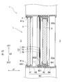
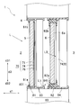
- FIG. 2 is a longitudinal sectional view of the double window of FIG. 1.
- 3A is an enlarged view of the deflection layer in the double window of FIG. 2, and
- FIG. 3B is an enlarged view showing a modification of the deflection layer of FIG. 3A.
- FIG. 14 is a longitudinal sectional view showing a deflection layer in a direction different from that in FIG. 13 in a tenth modification.
- the “vertical direction” in this specification is a direction that is not parallel to the horizontal direction in a plane parallel to the vertical direction, and does not necessarily match the vertical direction.
- “Upper” means one side in the vertical direction and the side (or direction) close to “upper” in the vertical direction.
- “Lower” refers to a side (or direction) opposite to “upper” in the vertical direction and close to “lower” in the vertical direction.
- a “sheet” is a concept including a member that can be called a film or a plate.
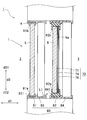
- FIG. 1 is a cross-sectional view showing the double window 1.
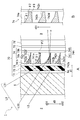
- 2 is a longitudinal sectional view of the double window 1 of FIG. 1, that is, a sectional view taken along the line II-II of FIG.
- FIG. 3A is an enlarged view of the deflection layer 74 in the double window 1 of FIG. 1 to 3A show an example in which a total reflection louver type deflection layer 74 is laminated on the indoor 3 side of the inner window 6.
- the double window 1 is installed in an opening 4 that opens toward the outdoor 2 and the indoor 3 between the adjacent outdoor 2 and the indoor 3.
- the outdoor 2 is an example of a first space
- the indoor 3 is an example of a second space.
- the double window 1 includes an outer window 5 that is an example of a first window and an inner window 6 that is an example of a second window.
- two outer windows 5 and two inner windows 6 are arranged.
- the inner window 6 is disposed on the indoor 3 side of the outer window 5 and can be moved relative to the outer window 5.
- Sunlight L is incident on the outer window 5 from the outdoor 2 side, and the incident sunlight L is emitted to the indoor 3 through the inner window 6.
- the double window 1 is provided with a light control sheet 70.
- light incident on the second space (indoor 3 in the figure) from the first space (outdoor 2 in the figure) is treated as sunlight.
- the present invention is not limited to this, and the incident light is derived from artificial light. It may be a thing.
- the outer window 5 and the inner window 6 are, for example, plate-like members made of glass or resin having visible light permeability.
- the thicknesses of the outer window 5 and the inner window 6 may be the same or different from each other. For example, the soundproofness can be improved by making the outer window 5 and the inner window 6 different in thickness.
- the light control sheet 70 is disposed on the surface 6a of the inner window 6 on the indoor 3 side, and has a sheet shape as a whole.
- the inner window 6 shown in FIGS. 1 to 3A is a single glass window.
- the light control sheet 70 is a sheet that does not have a protruding portion that protrudes greatly toward the indoor 3, thereby effectively avoiding the loss of the aesthetics of the opening 4, and double windows in various openings 4. 1 can be applied.
- the outer window 5 and the inner window 6 are held in the opening 4 by a holder 80.
- the holder 80 includes an outer window frame 81 that is an example of a first frame, an inner window frame 82 that is an example of a second frame, an outer window holder 83, and an inner window holder 84.
- the outer window holder 83 and the inner window holder 84 have rails 831 and 841 extending in a direction d2 (hereinafter referred to as a frontage direction) orthogonal to the opening direction d1 of the opening 4.
- the outer window 5 is held by the outer window holder 83 slidably, for example, slidable along the rail 831 with its outer peripheral edge held by the outer window frame 81.
- the inner window 6 is held by the inner window holder 84 so as to be movable along the rail 841, for example, slidable and removable, with a part or all of the outer peripheral edge thereof being held by the inner window frame 82.
- the inner window 6 may be, for example, rotatable (for example, inwardly opened or rotationally opened) or inclined (for example, inward) with respect to the outer window 5.
- the inner window 6 and the outer window 5 can move non-parallel to the opening direction d1 by being slidable along the rails 831 and 841 extending in the frontage direction d2.
- the inner window 6 may be fixed to the opening 4, while the outer window 5 may be attached to the opening 4 so as to be able to perform operations such as translation and rotation.
- the inner peripheries of the outer window frame 81 and the inner window frame 82 may be the same or different.
- the inner window frame 82 may have an inner circumference smaller than the outer window frame 81.
- the outer window frame 81 is difficult to enter the field of view, so that an aesthetic appearance can be ensured.
- the lower upper end 82 a of the inner window frame 82 is located above (d31 side) the lower upper end 81 a of the outer window frame 81.
- the reflected light L1 can be blocked by the inner window frame 82 so that the reflected light L1 irregularly reflected on the bottom surface of the outer window holder 83 (that is, the rail 831) or the bottom surface of the opening 4 does not travel to the indoor 3 side.
- the antiglare property can be improved.
- the upper lower end 82 b of the inner window frame 82 is positioned below (d32 side) than the upper lower end 81 b of the outer window frame 81.
- the upper lower end 82b of the inner window frame 82 is low so that the inner window 6 has an effect of eaves. I hardly receive it.
- the lower upper end 82a of the inner window frame 82 may be positioned above the lower upper end 81a of the outer window frame 81 in the range of 20 mm to 100 mm.
- the upper lower end 82b of the inner window frame 82 may be positioned below the upper lower end 81b of the outer window frame 81 in the range of 20 mm to 100 mm.
- the thickness of the air layer formed between the outer window 5 and the inner window 6 is not particularly limited, but may be within a range of 50 mm to 150 mm from the viewpoint of soundproofing and heat insulation, for example. Further, if air convection is generated inside the air layer, the heat insulation performance may be lowered. Therefore, in order to suppress the generation of convection, for example, it may be within a range of 50 mm to 80 mm.
- the thickness of an air layer refers to the space
- the outer window frame 81 and the inner window frame 82 may be formed of a material having lower thermal conductivity than a metal such as aluminum or a metal such as resin or wood.
- the outer window frame 81 and the inner window frame 82 may be formed by laminating metal, resin, and wood, or mixing wood with resin.
- the outer window frame 81 is formed of metal
- the inner window frame 82 is formed of resin.
- Both the outer window frame 81 and the inner window frame 82 may be formed of resin.
- the inner window frame 82 may be made of a material having high thermal conductivity so that latent heat generated in the deflection layer 74 described later can be easily released.
- the double window 1 may have a portion having an ultraviolet blocking function that absorbs or reflects ultraviolet rays on the outdoor 2 side of the deflection layer 74.
- the double window 1 may include a portion having a light diffusion function in the optical path from the outdoor 2 to the indoor 3 for incident light.
- the outdoor 2 side and / or the indoor 3 side of the deflecting layer 74. Includes a portion having a light diffusion function.
- the light control sheet 70 includes an ultraviolet absorbing adhesive layer 71 that is an example of a portion having an ultraviolet absorbing function, which is laminated on the surface 6 a of the inner window 6 on the indoor 3 side in the following order.
- the barrier layer 72, the first adhesive layer 73, the deflection layer 74, the second adhesive layer 75, and the light diffusion layer 76 which is an example of a portion having a light diffusion function.
- the ultraviolet absorbing function of the portion having the ultraviolet absorbing function for example, the light transmittance at a predetermined wavelength included in the wavelength range of 380 nm to 200 nm can be set to 5% or less. It is more preferable that the predetermined wavelength is included in a wavelength range of 380 nm to 300 nm because fading due to sunburn of furniture or goods caused by sunlight can be further suppressed.
- the light diffusion layer 76 can be omitted.
- the outer window 5 and / or the inner window 6 can be made of template glass, ground glass, frosted glass, or the like.
- the outer window 5 and the inner window 6 are an example of a portion having a light diffusion function provided on the outdoor 2 side of the deflection layer 74.
- the ultraviolet absorbing adhesive layer 71 can be omitted.
- a film having a function of reflecting or absorbing ultraviolet rays can be bonded to the outer window 5 and / or the inner window 6.
- the ultraviolet absorbing adhesive layer 71 is provided on the outdoor 2 side with respect to the deflection layer 74.
- the light control sheet 70 is fixed to the inner window 6 by the adhesive force of the ultraviolet absorbing adhesive layer 71.
- the ultraviolet absorbing pressure-sensitive adhesive layer 71 is, for example, an adhesive containing an ultraviolet absorber and having visible light permeability.
- the ultraviolet absorbing adhesive layer 71 absorbs the ultraviolet light L2 incident from the outdoor 2 side, thereby suppressing the ultraviolet light L2 from entering the deflection layer 74. Thereby, deterioration of the deflection layer 74 due to the ultraviolet ray L2 can be suppressed.
- the barrier layer 72 is fixed to the inner window 6 by the adhesive force of the ultraviolet absorbing adhesive layer 71.
- the barrier layer 72 is a film made of a resin such as PET (polyethylene terephthalate).
- PET polyethylene terephthalate
- the barrier layer 72 prevents the ultraviolet absorbent contained in the ultraviolet absorbing adhesive layer 71 from entering the deflection layer 74. Thereby, deterioration of the deflection
- the first adhesive layer 73 is, for example, an adhesive that does not contain an ultraviolet absorber and has visible light permeability.
- the deflection layer 74 is fixed to the barrier layer 72 by the adhesive force of the first adhesive layer 73.
- the deflection layer 74 is disposed on the indoor 3 side of the inner window 6.
- the deflection layer 74 is stacked on the inner window 6 so as to be movable relative to the outer window 5 together with the inner window 6.
- the deflection layer 74 deflects the visible light L3 incident from the outdoor 2 side and emits it to the indoor 3 side. That is, the deflection layer 74 has a daylighting function of adjusting the optical path of the light in the outdoor 2 and taking the light into the indoor 3.
- the deflection layer 74 in FIG. 3A includes a deflection layer main body 74a and a base material layer 74b.
- the base material layer 74b is, for example, a transparent or translucent resin film.
- the base material layer 74b is provided for manufacturing the deflection layer 74 in accordance with a manufacturing process described later.
- the base material layer 74b may be omitted.
- the deflection layer body 74 a includes a first portion 741, a second portion 742, and a third portion 743. Note that the third portion 743 is integrally formed with the first portion 741 using the same material as the first portion 741. Hereinafter, the first portion 741 and the third portion 743 are collectively referred to as an integral layer 744.
- the first portion 741 is bonded to the first adhesive layer 73 on the surface 741a on the outdoor two side.
- a plurality of substantially wedge-shaped grooves 741b are formed on the surface 741a of the first portion 741 at intervals in the vertical direction d3.
- Each groove 741b is formed in the first portion 741 over the entire region in the frontage direction d2 (see FIG. 1).
- the width of each groove 741b in the vertical direction d3 becomes narrower toward the indoor 3 side, that is, the third portion 743 side, and is finally closed in a state where the width is almost zero.
- the first portion 741 is made of a light transmissive material. This translucent material may be, for example, PET or acrylic resin.
- the second portion 742 is provided inside each groove 741b so as to fill each groove 741b.
- the second portion 742 has a shape that follows the groove 741b. Specifically, the second portion 742 has a side surface 742a, a steep slope 742b, a gentle slope 742c, and a bottom surface 742d.
- the side surface 742 a is flush with the surface 741 a of the first portion 741 and is bonded to the first adhesive layer 73.
- the steep slope 742b extends from the upper end of the side surface 742a toward the indoor 3 side, and is inclined downward d32 toward the indoor 3 side.
- the gentle slope 742c extends from the end of the steep slope 742b on the indoor 3 side toward the indoor 3 side, and is inclined downward d32 toward the indoor 3 side.
- the bottom surface 742d connects the lower end of the side surface 742a and the end of the gentle slope 742c on the indoor 3 side, that is, the lower end.
- the second portion 742 has a lower refractive index of visible light L3 than the first portion 741. Accordingly, the second portion 742 can totally reflect the visible lights L31 and L32 incident on the inclined surfaces 742b and 742c from the first portion 741 side, that is, the interface with the first portion 741 at an incident angle larger than the critical angle.
- the inclination angle ⁇ 1 of the steep slope 742b with respect to the opening direction d1 is larger than the inclination angle ⁇ 2 of the gentle slope 742c with respect to the opening direction d1.
- the inclination angle ⁇ 2 is 0 ° or more ( ⁇ 2 ⁇ 0). Since the inclination angle ⁇ 1 is larger than the inclination angle ⁇ 2, the steep slope 742b allows the visible light L31 from a high position on the outdoor 2 to enter at an incident angle larger than the critical angle, and the incident visible light L31 does not rise significantly and does not rise significantly. Total reflection is possible toward the back side of 3.
- the gentle slope 742c allows the visible light L32 from a low position in the outdoor 2 to be incident at an incident angle larger than the critical angle, and the incident visible light L32 does not rise significantly and does not rise significantly. Total reflection is possible toward the back side.
- the indoor 3 can be illuminated brightly. That is, the illumination effect of the light taken in can be improved.
- the visible lights L31 and L32 incident on the steep slope 742b or the gentle slope 742c are shown in a straight line, but in reality, they are refracted, that is, deflected every time they pass through interfaces having different refractive indexes.
- the second portion 742 has a main portion 742e that functions as an adhesive, and an optional functional material 742f dispersed in the main portion 742e.
- the main portion 742e is formed of a material having a lower refractive index than the first portion 741.
- the material of the main portion 742e may be a resin material, for example, an ionizing radiation curable resin that is cured by irradiation with ionizing radiation.
- the ionizing radiation curable resin may be, for example, an ultraviolet curable resin, an electron beam curable resin, a visible light curable resin, or a near infrared curable resin.
- the linear expansion coefficient of the main portion 742e is desirably the same as or close to the linear expansion coefficient of the first portion 741. By making the linear expansion coefficient of the main portion 742e the same as or close to the linear expansion coefficient of the first portion 741, separation of the second portion 742 from the first portion 741 due to thermal expansion of the main portion 742e can be suppressed.
- the functional inclusion 742f is dispersed in the main portion 742e in anticipation of various functions.
- a heat ray absorbing material may be employed as the functional inclusion 742f.
- the heat ray absorbing material may be, for example, transparent inorganic nanoparticles.
- Inorganic nanoparticles include, for example, antimony tin oxide (ATO), indium tin oxide (ITO), lanthanum hexaboride (LaB6), aluminum doped zinc oxide, indium doped zinc oxide, gallium doped zinc oxide, tungsten oxide, six It may be nanoparticles of cerium boride, anhydrous zinc antimonate and copper sulfide or a mixture thereof.
- ATO antimony tin oxide
- ITO indium tin oxide
- LaB6 lanthanum hexaboride
- Al doped zinc oxide aluminum doped zinc oxide
- indium doped zinc oxide gallium doped zinc oxide
- tungsten oxide six
- It may be nanoparticles of cerium boride, anhydrous zinc antimonate and copper sulfide or a mixture thereof.
- a coloring material may be employed as the functional content 742f.
- the colorant may be a pigment, and more specifically, a black pigment such as carbon black, graphite, or titanium nitride.
- the deflection layer 74 can exhibit the light blocking function of the visible light L3.
- bluish particles such as amber, blue, and purple, reddish particles, yellowish particles, and the like may be used as the colorant.
- the second portion 742 of the deflection layer 74 may be composed of two or more layers having different functions.
- the layer on the outdoor side of the second portion 742 may have a heat shielding function
- the layer on the indoor side of the second portion 742 may have a design function.
- the deflection layer 74 can be manufactured, for example, as follows. First, an integrated layer 744 of the first portion 741 and the third portion 743 is made of a material such as ionizing radiation curable epoxy acrylate. Specifically, a mold roll having a convex portion corresponding to the configuration (that is, arrangement, shape, etc.) of the groove 741b of the first portion 741 is prepared. Next, a sheet of the base material layer 74b is fed between the mold roll and the nip roll, and a curable material is supplied between the mold roll and the base material layer 74b in accordance with the feeding of the sheet.
- a material such as ionizing radiation curable epoxy acrylate.
- the curable material is pressed with a mold roll and a nip roll so that the liquid curable material supplied onto the base material layer 74b is filled in the concave portion of the mold roll.
- the surface 741a and the groove are formed on the curable material while securing the third portion 743 by supplying the curable material onto the base material layer 74b so that the mold roll and the base material layer 74b do not contact each other.
- the shape of 741b is transferred.
- the integral layer 744 is obtained by irradiating the curable resin with light to cure (solidify) the curable material.
- a liquid composition containing a curable material such as urethane acrylate that forms the main portion 742e by curing and a functional content 742f is supplied to the integrated layer 744.
- the composition is filled into each groove 741b of the first portion 741 using a doctor blade.
- the excess composition overflowing out of the groove 741b is scraped off with a doctor blade.
- the 2nd part 742 is obtained by irradiating ionizing radiation and hardening a composition. In this way, the deflection layer 74 having the base layer 74b and the deflection layer body 74a is manufactured.
- FIG. 3B is an enlarged view showing a modification of the deflection layer 74 of FIG. 3A.
- the deflection layer 74 may be inclined upward d31 as the bottom surface 742d moves toward the indoor 3 side.
- the deflecting layer 74 may be made of a material having a lower refractive index than the deflecting layer body 74a that does not include the functional inclusion 742f.
- the inclination angle ⁇ 1 of the steep slope 742b with respect to the opening direction d1 is larger than the inclination angle ⁇ 2 of the gentle slope 742c with respect to the opening direction d1.
- the inclination angle ⁇ 2 is 0 ° or more ( ⁇ 2 ⁇ 0).
- the inclination angle ⁇ 3 of the bottom surface 742d with respect to the opening direction d1 is smaller than ⁇ 1 ( ⁇ 1> ⁇ 3).
- the second adhesive layer 75 is, for example, an adhesive that does not contain an ultraviolet absorber and has visible light permeability.
- the light diffusion layer 76 is fixed to the deflection layer 74 by the adhesive force of the second adhesive layer 75.
- the light diffusion layer 76 is disposed on the indoor 3 side of the deflection layer 74.
- the light diffusion layer 76 diffuses the visible light L ⁇ b> 3 deflected by the deflection layer 74 and emits it to the indoor 3.
- the light diffusion layer 76 may be, for example, template glass, frosted glass, or frosted glass. According to the light diffusion layer 76, a diffused light distribution obtained by diffusing the visible light L3 deflected by the deflection layer 74 can be obtained, so that the indoor 3 can be illuminated uniformly and brightly. In addition, by providing the light diffusion layer 76, it is possible to reduce the glare that can be seen from the indoor side according to the repeated arrangement of the first portion 741 and the second portion 742 having different refractive indexes. .
- the double window 1 configured as described above can be assembled using, for example, a double window kit including the inner window 6, the light control sheet 70, the inner window frame 82, and the inner window holder 84 as follows. it can. In the following example, it is assumed that the outer window 5, the outer window frame 81, and the outer window holder 83 are already provided in the opening 4.
- the light control sheet 70 is affixed to the inner window 6 via the ultraviolet absorbing adhesive layer 71.
- the light control sheet 70 may be attached at any of the manufacturing stage of the inner window 6 and the assembly stage (that is, the construction stage) of the double window 1.
- the light control sheet 70 before being attached to the inner window 6 may have a release sheet attached to the ultraviolet absorbing adhesive layer 71.
- the inner window frame 82 is attached to the outer periphery of the inner window 6 and the light control sheet 70.
- the inner window frame 82 may be attached either before the assembly step to the opening of the double window 1 or during the assembly step to the opening of the double window 1.
- the inner window holder 84 is installed in the opening 4 so as to be adjacent to the outer window holder 83 on the indoor 3 side.
- the inner window holder 84 may be installed by fixing the inner window holder 84 to the opening 4 by screwing or the like. Next, the inner window 6 is fitted into the inner window holder 84 and attached.
- the double window 1 can be easily assembled by combining the existing outer window 5 and the double window kit.
- an auxiliary material called a fusible frame at the lower end on the indoor 3 side of the opening 4 May be installed.
- the inner window holder 84 is mounted substantially horizontally.
- the inner window 6 is attached to be within 3 ° from the horizontal.
- the reflection surface of the deflection layer 74 laminated on the inner window 6 may take an angle that is not intended in design. In such a case, the angle of the inner window 6 may be adjusted by disposing an angle adjusting attachment (not shown) below the inner window holder 84.
- the second portion 742 of the deflection layer 74 has a reflective surface that is asymmetric in a longitudinal sectional view.
- the inner window 6 is configured to be detachable from the inner window holder 84, it is asymmetrical by attaching the inner window 6 to the inner window holder 84 by turning it upside down in consideration of the incident angle of light and the necessity of daylighting. You may use a reflective surface properly.
- the sunlight L incident on the inner window 6 is incident on the ultraviolet absorbing adhesive layer 71 immediately after passing through the inner window 6.
- the ultraviolet L2 is absorbed by the ultraviolet absorbing adhesive layer 71 and hardly transmits. Since the ultraviolet ray L2 hardly passes through the ultraviolet absorbing adhesive layer 71, the incidence of the ultraviolet ray L2 on the deflection layer 74 located on the emission side of the ultraviolet absorbing adhesive layer 71 is suppressed. Thereby, deterioration of the deflection layer 74 due to the ultraviolet ray L2 can be suppressed.
- the visible light L3 passes through the ultraviolet absorbing adhesive layer 71 with almost no absorption.
- the visible light L3 that has passed through the ultraviolet absorbing adhesive layer 71 passes through the barrier layer 72 and the first adhesive layer 73 in order and then enters the deflection layer 74.
- the visible light L3 incident on the surface 741a of the first portion 741 travels inside the first portion 741, and has an interface 742b with the second portion 742 having a lower refractive index than the first portion 741. Incident to 742c.
- the steep slope 742b has a posture ( ⁇ 1> ⁇ 2) nearly parallel to the visible light L31 from a high position
- the visible light L31 from a high position is larger than the critical angle on the steep slope 742b. Easy to enter at an incident angle. Thereby, the visible light L31 from a high position can be reliably totally reflected by the steep slope 742b.
- the steep slope 742b is inclined downward d32, the total reflection direction by the steep slope 742b is close to the horizontal direction, that is, the opening direction d1. Thereby, the rising of visible light L31 from a high position can be suppressed, and visible light L31 can be totally reflected toward the back side of indoor 3.
- the gentle slope 742c has a posture ( ⁇ 2 ⁇ 0) that is nearly parallel to the visible light L32 from a low position, the visible light L32 from the low position is more than the critical angle on the gentle slope 742c. Easy to enter at a large incident angle. Thereby, the visible light L32 from a low position can be reliably totally reflected by the gentle slope 742c.
- the gentle slope 742c is inclined downward d32, the total reflection direction by the gentle slope 742c is close to the horizontal direction. Thereby, the rising of the visible light L32 from a low position is suppressed, and the visible light L32 can be totally reflected toward the back side of the indoor 3.
- the visible light L3 incident on the side surface 742a of the second portion 742 is incident on the functional content 742f and is affected by the functional content 742f.
- the functional inclusion 742f is a heat-absorbing material, the heat of visible light L3 can be absorbed and the transfer of heat to the indoor 3 side can be suppressed.
- the visible light L 3 emitted from the deflection layer 74 passes through the second adhesive layer 75 and enters the light diffusion layer 76.
- the visible light L3 incident on the light diffusion layer 76 is diffused and emitted to the indoor 3.
- the light from the outdoor 2 is deflected by the deflecting layer 74 and taken into the indoor 3, so that the illumination effect of the taken light can be improved while avoiding direct light.
- the light diffusion layer 76 can be omitted.
- the outer window 5 and / or the inner window 6 can be made of template glass, ground glass, frosted glass, or the like.
- the ultraviolet absorbing adhesive layer 71 can be omitted.
- a film having a function of reflecting or absorbing ultraviolet rays can be bonded to the outer window 5 and / or the inner window 6.
- the double window 1 of the present embodiment is not limited to the configuration shown in FIGS. 1 to 3A, and can be variously changed as shown in the following modifications.
- the same reference numerals as those used for the corresponding parts in the above embodiment are used for the parts that can be configured in the same manner as in the above embodiment.
- the duplicated explanation is omitted.
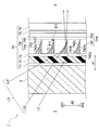
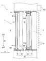
- FIG. 4 is a longitudinal sectional view showing an example in which a deflection layer 74 is laminated on the outdoor 2 side of the inner window 6 as the double window 1 according to the first modification.
- the light control sheet 70 is laminated in the following order on the surface 6b on the outdoor 2 side of the inner window 6, in the following order: an adhesive layer 202, a light diffusion layer 76, an adhesive layer 75, It has the hard coat layer 201 which is an example of the part which has the deflection
- the hard coat layer 201 has weather resistance, light transmissivity, and scratch resistance that hardly causes deterioration due to ultraviolet rays, heat, water, chemicals, temperature changes, and the like.
- the hard coat layer 201 may be formed, for example, by applying an electron beam curable transparent resin to which an ultraviolet absorber is added on the deflecting layer 74 and curing the applied transparent resin by electron beam irradiation.
- an ultraviolet adhesive layer 71 similar to that shown in FIG. 3A may be disposed between the hard coat layer 201 and the deflection layer 74.
- the ultraviolet absorbing adhesive layer 71 can be omitted, or the ultraviolet adhesive layer 71 and the outer window 5 having an ultraviolet blocking function can be used in combination.
- the inner window 6 instead of providing the light diffusion layer 76, the inner window 6 itself may have a light diffusion function.
- the inner window 6 may be a template glass, frosted glass, or frosted glass, or a light diffusing agent is dispersed in the inner window 6 or a layer having a light diffusing function is provided. Or you may.
- the visible light L3 can be deflected by the deflecting layer 74 and taken into the indoor 3 in the same way as the double window 1 of the above-described embodiment and modified example, so that direct light is reduced.
- the illumination effect of the light taken in can be improved.
- the visible light L3 deflected by the deflection layer 74 is diffused by the light diffusion layer 76, so that the indoor 3 can be illuminated brightly.
- the deterioration of the deflection layer 74 due to the ultraviolet ray L2 can be suppressed.
- the deflection layer 74 can be protected by the hard coat layer 201, the weather resistance of the deflection layer 74 can be improved. Further, in the first modified example, since the deflection layer 74 is disposed so as to avoid the indoor side, the chance of dirt adhering to the surface of the deflection layer 74 is reduced.
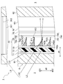
- FIG. 5 is a longitudinal sectional view showing an example in which a deflection layer 74 is laminated on the indoor 3 side of the outer window 5 as the double window 1 according to the second modification.
- FIG. 5 corresponds to a case in which the inner window 6 in FIG. That is, instead of laminating the light control sheet 70 shown in FIG. 3A on the surface of the inner window 6 on the indoor 3 side, the light control sheet 70 may be laminated on the surface of the outer window 5 on the indoor 3 side.
- the outer window 5 has an ultraviolet blocking function, the ultraviolet absorbing adhesive layer 71 can be omitted.
- the deflecting layer 74 is disposed on the outer window 5 side, not on the inner window 6 that is in contact with the indoor 3 and is likely to cause condensation. Therefore, it is possible to suppress the occurrence of mold on the deflection layer 74 or the occurrence of peeling due to condensation.
- the second modified example similarly to the double window 1 of the above-described embodiment and modified example, it is possible to improve the illumination effect of the light taken in while reducing the direct light by the deflection layer 74.
- the deflection layer 74 is arranged so as to avoid the indoor side, the chance that dirt adheres to the surface of the deflection layer 74 is reduced.
- FIG. 6 is a longitudinal sectional view showing an example in which a deflection layer 74 is laminated on the outdoor 2 side of the outer window 5 as the double window 1 according to the third modification.
- FIG. 6 corresponds to the first modified example (FIG. 4) in which the inner window 6 is replaced with the outer window 5. That is, instead of laminating the light control sheet 70 shown in FIG. 4 on the surface of the inner window 6 on the outdoor 2 side via the adhesive layer 202, the adhesive layer 202 is formed on the surface of the outer window 5 on the outdoor 2 side. You may laminate through. Further, in the example shown in FIG.
- the deflection layer 74 is disposed on the outdoor 2 side from the outer window 5, and thus is more easily deteriorated due to scratches and wind and rain than when disposed on the indoor 3 side. For this reason, on the outdoor 2 side of the deflection layer 74, a hard coat layer 201 having not only an ultraviolet absorbing function but also excellent scratch resistance and water resistance is disposed. By disposing the hard coat layer 201, deterioration of the deflection layer 74 due to scratches or wind and rain can be suppressed. Further, on the indoor 3 side of the deflection layer 74, a light diffusion layer 76 is arranged in the same manner as in the embodiment and the modification described above.
- the light diffusion layer 76 may be fixed to the deflection layer 74 via an adhesive layer, or may be coated on the deflection layer 74.
- the deflecting layer 74 is disposed on the outer window 5 side, not on the inner window 6 where the dew layer 74 is in contact with the indoor 3 and condensation is likely to occur. Therefore, it is possible to suppress the occurrence of mold on the deflection layer 74 or the occurrence of peeling due to condensation.
- FIG. 7 is a longitudinal sectional view showing an example in which a deflection layer 74 is arranged inside the inner window 6 as the double window 1 according to the fourth modification.
- the inner window 6 of the fourth modification is an embodiment of double-glazed glass, and the deflection layer 74 is combined with double-glazed glass.
- the inner window 6 of the fourth modified example includes, in order from the outdoor 2 side, a first inner window substrate 61, a light control sheet 70 having the configuration shown in FIG. 3A, an intermediate layer 63, and a second inner window. And a window substrate 62.
- at least one of the first inner window substrate 61 and the second inner window substrate 62 may be provided with a thermal barrier coating called a Low-E metal film.
- the first inner window substrate 61 and the second inner window substrate 62 are connected by a frame-shaped spacer 301 disposed between the peripheral portions of the inner window substrates 61 and 62.
- a sealant 302 is provided on the outer peripheral surface of the spacer 301.
- the intermediate layer 63 may be filled with an inert gas such as air or argon, or the intermediate layer 63 may be in a vacuum state.
- the deflection layer 74 is laminated on the first inner window substrate 61, but the deflection layer 74 in the second modification (see FIG. 4) is formed on the second inner window substrate 62. It may be laminated on top.
- the second window 6 including the deflection layer 74 has a configuration called a so-called pair glass as a whole, a pair of inner window substrates 61 and 62 whose relative positions are positioned and a gap is formed between them. have.
- the present invention is not limited to the illustrated example, and the inner window 6 may have a configuration called so-called laminated glass, and the intermediate layer 63 may be deleted. Further, the number of substrates constituting the inner window 6 may be three or more.
- the distance between the first inner window substrate 6 and the second inner window substrate 62 may be, for example, within 20 mm in consideration of heat insulation.
- the fourth modified example similarly to the double window 1 of the above-described embodiment and modified example, it is possible to improve the illumination effect of the light taken in while reducing the direct light by the deflection layer 74. Moreover, since the heat insulation effect can be enhanced by using the double-glazed glass, the energy consumption for operating the air conditioner can be suppressed.
- the deflection layer 74 or the light control sheet 70 is disclosed as a component different from the inner window 6 or the outer window 5
- at least one of the inner window 6 and the outer window 5 has two or more transparent plates.
- FIG. 8 is a longitudinal sectional view showing an example in which a deflection layer 74 is arranged inside the outer window 5 as the double window 1 according to the fifth modification.
- the inner window 6 was the aspect of multilayer glass
- the outer window 5 is the aspect of multilayer glass.
- FIG. 8 corresponds to a structure in which the first inner window substrate 61 in FIG. 7 is replaced with the first outer window substrate 51 and the second inner window substrate 62 in FIG. 7 is replaced with the second outer window substrate 52.
- the intermediate layer 63 may be deleted.
- the fifth modified example similarly to the double window 1 of the above-described embodiment and modified example, it is possible to improve the illumination effect of the light taken in while avoiding direct light by the deflection layer 74. Moreover, the energy consumption of an air conditioner can be reduced by improving the heat insulation effect of the double window 1.
- the deflection layer 74 may be disposed apart from the inner window 6 and the outer window 5.
- the deflection layer 74 may be provided with a gap with respect to the inner window 6 and the outer window 5, and may be movable relative to the inner window 6 and the outer window 5.
- the deflecting layer 74 may be configured to always face the outer window 5, or drawn out from a storage space (not shown) at the upper end or the lower end inside the opening 4 to be in time with the outer window 5. You may be comprised so that it may oppose. Thereby, the user can freely select the field of view.
- FIG. 9 is a longitudinal sectional view showing an example in which a deflection layer 74 is arranged on the outdoor 2 side of the outer window 5 through a gap as the double window 1 according to the sixth modification.
- the deflection layer 74 of the sixth modification is held by the holder 401 at the end of the opening 4 on the outdoor 2 side. More specifically, the deflection layer 74 is movable, for example, slidable along the rail 402 of the holder 401 extending in the frontage direction d2 in the frontage direction d2.
- the movement of the deflection layer 74 can be performed independently of the movement of the outer window 5 and the movement of the inner window 6.
- the holder 401 may be integrated with the outer window holder 83, and the deflection layer 74 may not be able to move relative to the outer window holder 83.
- the deflection layer 74 may be parallel to the outer window 5 and the inner window 6 or may be non-parallel. If standing, the position of the holder 401 may be adjusted, and the deflection layer 74 may be inclined with respect to the outer window 5 to be configured like a shade.
- the deflection layer 74 of the sixth modified example is disposed on the outdoor 2 side from the outer window 5, it is more likely to be deteriorated due to scratches or wind and rain than when disposed on the indoor 3 side. For this reason, on the outdoor 2 side of the deflection layer 74, a hard coat layer 201 having not only an ultraviolet absorbing function but also excellent scratch resistance and water resistance is disposed. By disposing the hard coat layer 201, deterioration of the deflection layer 74 due to scratches or wind and rain can be suppressed. Further, on the indoor 3 side of the deflection layer 74, a light diffusion layer 76 is arranged in the same manner as in the embodiment and the modification described above. The light diffusion layer 76 may be fixed to the deflection layer 74 via an adhesive layer, or may be coated on the deflection layer 74.
- the deflection layer 74 similarly to the double window 1 of the above-described embodiment and modified example, it is possible to improve the illumination effect of the light taken in while avoiding direct light by the deflection layer 74.
- the deflection layer 74 by arranging the deflection layer 74 on the outdoor 2 side of the outer window 5, light with a high incident angle can be deflected in the direction of a low incident angle, and reflection loss at the window surface can be minimized. More light amount of sunlight L can be taken in by the deflection layer 74.
- the deflection layer 74 is provided at a position on the outdoor side with respect to the outer window 5 with a gap from the inner window 6 and the outer window 5.
- An example is shown.
- the deflection layer 74 is provided at a position between the outer window 5 and the inner window 6 via a gap with respect to the inner window 6 and the outer window 5. It may be done.
- the deflecting layer 74 may be configured to always face the outer window 5 and the inner window 6, or may be drawn out from the storage space (not shown) at the upper or lower end inside the opening 4. You may be comprised so that it may oppose the window 5 and the inner window 6 timely. Thereby, the user can freely select the field of view.
- FIG. 10 is a longitudinal sectional view showing an example in which a deflection layer 74 is arranged on the indoor 3 side of the outer window 5 through a gap as the double window 1 according to the seventh modification. Further, in the double window 1 according to the seventh modified example, the deflection layer 74 is disposed on the outdoor 2 side of the inner window 6 from the inner window 6 via a gap. The deflection layer 74 of the seventh modified example is held by the holder 801 between the outer window 5 and the inner window 6 in the opening 4. More specifically, the deflection layer 74 is movable in the frontage direction d2 along the rail 802 of the holder 801 extending in the frontage direction d2, and is slidable.
- deviation layer 74 of FIG. 10 is 1 sheet sash, you may make it 2 sheets.
- a hard coat layer 201 containing an ultraviolet absorber is disposed on the outdoor 2 side of the deflecting layer 74 as in the sixth modified example (FIG. 9).
- a light diffusion layer 76 is disposed on the indoor 3 side of the deflection layer 74.
- the movement of the deflection layer 74 can be performed independently of the movement of the outer window 5 and the movement of the inner window 6.
- the holder 801 may be integrated with the inner window holder 84, and the deflection layer 74 may not be able to move relative to the outer window holder 83.
- the seventh modified example similarly to the double window 1 of the above-described embodiment and modified example, it is possible to improve the illumination effect of the light taken in while avoiding direct light by the deflection layer 74.
- the deflection layer 74 is located on the outdoor side of the outer window 5 or at a position between the outer window 5 and the inner window 6.
- An example is shown in which the inner window 6 and the outer window 5 are provided via gaps.
- the deflection layer 74 is provided at a position closer to the indoor side than the inner window 6 with respect to the inner window 6 and the outer window 5 via a gap.
- the deflecting layer 74 may be configured to always face the inner window 6, or may be drawn out from a storage space (not shown) at the upper or lower end inside the opening 4 to be in time with the inner window 6. You may be comprised so that it may oppose. Thereby, the user can freely select the field of view.
- FIG. 11 is a longitudinal sectional view showing an example in which a deflection layer 74 is disposed on the indoor 3 side of the inner window 6 through a gap as the double window 1 according to the eighth modification.
- the deflection layer 74 of the eighth modification is held by the holder 801 on the indoor side of the inner window 6 in the opening 4. More specifically, the deflection layer 74 is movable in the frontage direction d2 along the rail 802 of the holder 801 extending in the frontage direction d2, and is slidable.
- deviation layer 74 of FIG. 11 is 1 sheet sash, you may make it 2 sheets.
- a coat layer 201 is disposed.
- a light diffusion layer 76 is disposed on the indoor 3 side of the deflection layer 74.
- the movement of the deflection layer 74 can be performed independently of the movement of the outer window 5 and the movement of the inner window 6.
- the holder 801 may be integrated with the inner window holder 84, and the deflection layer 74 may not be able to move relative to the outer window holder 83.
- FIG. 12 is a perspective view showing a deflection layer 74 supported as a double window 1 according to a ninth modification so as to be rotatable about a predetermined axis.
- the deflection layer 74 of the ninth modification includes a louver type deflection layer (see FIG. 3A and the like) that deflects light by total reflection, a louver type deflection layer (see FIG. 20) that deflects light by specular reflection, and a prism type.
- the deflection layer (see FIG. 18) and the craze type deflection layer (see FIG. 19) may be used.
- the deflection layer 74 of the ninth modification is supported rotatably about an axis extending in the frontage direction d2.
- the double window 1 according to the fourteenth modification includes a support shaft member 142 connected to the deflection layer 74 and a drive device 143 capable of driving the support shaft member 142.
- the support shaft member 142 extends in the frontage direction d2.
- the orientation of the deflection layer 74 can be adjusted according to the installation position, time, time, and the like.
- deviation layer 74 can exhibit scheduled functions, such as a daylighting function, a light shielding function, a heat shielding function, with respect to sunlight irrespective of time and time.
- the orientation of the deflection layer 74 is adjusted so that the bottom surface 742d of the deflection layer 74 in FIG.
- FIG. 12 the specific configuration shown in FIG. 12 is merely an example of a support method that allows the orientation of the deflection layer 74 to be varied.
- FIGS. 13 to 16 show another example of a configuration for supporting the deflection layer 74 so that the orientation of the deflection layer 74 can be changed as a tenth modification.
- FIG. 13 is a longitudinal sectional view showing an example in which a deflection layer 74 is arranged on the indoor 3 side of the inner window 6 through a gap as the double window 1 according to the tenth modification.
- FIG. 14 is a perspective view showing a double window 1 according to a tenth modification.
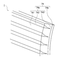
- FIG. 15 is an enlarged perspective view of the deflection layer 74 in the double window 1 of the tenth modification.
- the main portion 742e and the functional inclusion 742f (see FIG. 3A) constituting the second portion 742 are not shown.
- the double window 1 of the tenth modification includes a plurality of strip-shaped deflection layers 74 arranged in the vertical direction d ⁇ b> 3 and each deflection layer 74 so that the orientation of each deflection layer 74 can be changed.
- a support member 101 that supports In the tenth modification the deflection layer 74 has a so-called blind mode.
- the deflection layer 74 is arranged at a position facing the inner window 6 on the indoor 3 side.
- the deflection layer 74 of the tenth modified example is also called a slat or a blade plate, and is formed as a thin plate-like member that is elongated in the frontage direction d2.
- the deflection layer 74 of the tenth modification is formed in a slightly curved thin plate shape.
- the double window 1 of the tenth modified example has a mounting box 102, a ladder cord 103, a lifting / lowering cord 104, and an operation grip 105.
- the attachment box 102 is a fixture for attaching the deflection layer 74 to the wall.
- the ladder cord 103 hangs down from the mounting box 102 and supports each deflecting layer 74 in a state of being spaced apart in the vertical direction d3.
- the lifting / lowering cord 104 can pull up the deflection layer 74.
- the operation grip 105 is connected to the lifting / lowering cord 104, the ladder cord 103 and the lifting / lowering cord 104.
- the ladder code 103 controls the direction of each deflection layer 74, that is, the normal direction of the sheet surface of each deflection layer 74, so that each deflection layer 74 is substantially parallel.
- the direction of the deflection layer 74 can be adjusted.
- the direction of each deflection layer 74 is changed so as to rotate about an axis parallel to the longitudinal direction d2.
- each deflection layer 74 can be pulled up so as to narrow the interval in the vertical direction d3 sequentially from the deflection layer 74 on the lower d32 side. At this time, at least a part of each deflection layer 74 is accommodated in the mounting box 102, and the inner window 6 is exposed to the indoor 3. Similarly, by operating the lifting / lowering cord 104 via the operation grip 105, the deflection layer 74 gathered upward can be lowered to a position facing the inner window 6.
- the deflection layer 74 when the sheet surface of the deflection layer 74 extends substantially in the vertical direction d3, various functions expected for the deflection layer 74 with respect to sunlight L from the outdoors 2, for example, A lighting function, a light shielding function, a heat shielding function, etc. can be exhibited.
- the deflection layer 74 is changed with respect to the sunlight L from the sun whose altitude is changed by changing the direction of all the deflection layers 74 using the ladder code 103. Effectively perform planned functions.
- FIG. 16 is a longitudinal sectional view showing a deflecting layer 74 in a different direction from FIG. 13 in the tenth modification.
- the direction of the deflection layer 74 may be adjusted as shown in FIG. 16 so that the sunlight L passes between the neighboring deflection layers 74.
- this method compared with the case where sunlight L permeate
- the 2nd part 742 contains the functional substance 742f (refer FIG. 3A) which has visible-light-shielding property, in the state shown by FIG. It is also possible to prevent peeping from the opening direction d1.
- the light from the outdoor 2 is deflected by the deflecting layer 74 and taken into the indoor 3 so that the direct light can be obtained. While avoiding, the illumination effect of the light taken in can be improved.
- the deflection layer 74 has a daylighting function, a light shielding function, a heat shielding function, etc. The planned function can be demonstrated.
- the deflection layer 74 illustrated in the embodiment and the modification described above has a size facing the entire area of the outer window 5 and the inner window 6.
- the present invention is not limited to this example, and the deflection layer 74 may be disposed only in a part of the region facing the outer window 5 or may be disposed only in a part of the region facing the inner window 6. Good.
- FIG. 17 is a longitudinal sectional view showing an example in which the deflection layer 74 is partially arranged on the inner window 6 and the outer window 5 as the double window 1 according to the eleventh modification.
- the deflection layer 74 is disposed in a region facing the upper half of the outer window 5 and a region facing the lower half of the inner window 6. More specifically, the deflection layer 74 shown in FIG. 17 is partially laminated on the surface 5 a on the indoor 3 side of the outer window 5 and the surface 6 a on the indoor 3 side of the inner window 6.
- the deflection layer 74 of FIG. 17 is laminated on the upper half of the surface 5a of the outer window 5 and the lower half of the surface 6a of the inner window 6, it is not limited to such a configuration.
- the deflection layer 74 may be laminated on the lower half of the surface 5 a of the outer window 5 and the upper half of the surface 6 a of the inner window 6. Further, the deflection layer 74 may be laminated at the central portion in the vertical direction d3 of the surface 5a of the outer window 5 or the surface 6a of the inner window 6. By arranging the deflection layer 74 at the center of the outer window 5 or the inner window 6 in the vertical direction d3, it is deflected from below the height of the human line of sight, depending on the height of the opening 4 and the depth in the frontage direction.
- the deflection layer 74 may be partially laminated on the surface 5 b on the outdoor 2 side of the outer window 5 and the surface 6 b on the outdoor 2 of the inner window 6. Further, the deflection layer 74 may be partial to the surfaces 5a and 5b of the outer window 5 and the surfaces 6a and 6b of the inner window 6 not only in the vertical direction d3 but also in the frontage direction d2. Good.
- the deflection layer 74 having a size that is partially projected on the inner window 6 and the outer window 5 in the opening direction d1 is provided on the outdoor 2 side of the outer window 5, between the outer window 5 and the inner window 6, or on the inner side. You may arrange
- the illumination effect of the light taken in while avoiding direct light by the deflection layer 74 can be improved.
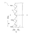
- FIG. 18 is a longitudinal sectional view showing a prism type deflection layer 74 as the double window 1 according to the twelfth modification.
- the deflection layer 74 of the twelfth modification is a prism form.
- the deflection layer 74 has a prism surface 7400, and deflects the visible light L ⁇ b> 3 by reflection or refraction at the prism surface 7400 to be taken into the indoor 3.
- the deflection layer 74 of the twelfth modification has a sheet-like main body portion 7401 and a plurality of unit prisms 7402 arranged on the main body portion 7401.
- the main body portion 7401 and the unit prism 7402 are made of a translucent material.
- the unit prisms 7402 are arranged in the vertical direction d3 and extend in the frontage direction d2.
- Each unit prism 7402 is arranged on one surface of the main body portion 7401 without any gap.
- the unit prism 7402 has a first surface 7402a and a second surface 7402b arranged to face each other in the vertical direction d3.
- the deflection layer 74 reflects, in particular, totally reflects the visible light L3 incident on the unit prism 7402 from one of the first surface 7402a and the second surface 7402b on the other of the first surface 7402a and the second surface 7402b. Accordingly, the deflection layer 74 can deflect the visible light L3 and emit it to the indoor 3 side.
- the illumination effect of the light taken in while avoiding the direct light can be improved by the deflection layer 74 as in the double window 1 of the embodiment and the modification described above. Further, according to the twelfth modification, the number of parts of the deflection layer 74 can be reduced by configuring the deflection layer 74 with a prism.
- FIG. 19 is a longitudinal sectional view showing a craze-type deflection layer 74 as the double window 1 according to the thirteenth modification.
- the deflection layer 74 of the thirteenth modification is a craze mode.
- the term “craze” (sometimes referred to as “craze”) refers to a substantially linear crack or crack formed in a resin film.
- the craze in the thirteenth modified example is one in which resin fibrils (that is, fibrous resin) remain between the wall surfaces of cracks or cracks formed in the resin film, and no resin fibrils remain. It is different from a crack.
- the deflection layer 74 of the thirteenth modification has a main body portion 7410 made of a resin film and a plurality of crazes 7411 formed on the surface 7410 a on the outdoor 2 side of the main body portion 7410.
- the craze 7411 is, for example, a straight plate with a sharp tip such as a blade or blade, and can be obtained by imparting a minute bending deformation along the straight line to the resin film.
- the visible light L3 incident on the craze 7411 of the deflecting layer 74 travels in the craze 7411 and then the resin fibril 7411a (that is, the high refractive index layer). It is incident on the gap 7411b (that is, the low refractive index layer).
- the gap 7411b that is, the low refractive index layer.
- FIG. 19 only one gap 7411b is representatively shown.
- the illumination effect of the light taken in can be improved by reducing the direct light by the deflection layer 74.
- the number of parts of the deflection layer 74 can be reduced by configuring the deflection layer 74 with crazes.
- FIG. 20 is a longitudinal sectional view showing a mirror louver type deflection layer 74 as the double window 1 according to the fourteenth modification.
- the deflection layer 74 of the twelfth modification has a plurality of blades 7415 arranged at intervals in the vertical direction d3. Each blade 7415 deflects the visible light L3 toward the indoor 3 side by specularly reflecting the visible light L3 on its upper surface 7415a.
- the deflection layer 74 shown in FIG. 20 is prepared by preparing a transparent base material with a cut 7416 and then filling the transparent base cut 7416 with a high reflectivity material such as aluminum. obtain.
- the upper surface 7415a of the blade 7415 is formed of a high reflectivity material such as aluminum.
- the blade 7415 may be formed as a gap. In this example, total reflection due to the difference in refractive index between the transparent substrate and the blade 7415 made of a gap can be caused, and a deflection function that does not cause reflection loss due to total reflection can be expected.
- FIG. 21 is a longitudinal sectional view showing an example in which an angle-dependent light control sheet 7420 is arranged on the indoor 3 side of the deflection layer 74 as the double window 1 according to the fifteenth modification.
- a deflection layer 74 is laminated on the outer window 5
- an angle-dependent light control sheet 7420 is laminated on the inner window 6.
- the angle-dependent light control sheet 7420 selectively scatters only incident light from a predetermined angle range and transmits other incident light.
- the angle-dependent light control sheet 7420 maintains a resin composition containing at least two types of photopolymerizable oligomers or monomers in a film form, and cures the film form body by irradiating ultraviolet rays from a predetermined direction. You may form by doing.
- the angle-dependent light control sheet 7420 of the fifteenth modified example has an optical characteristic of scattering the visible light L3 incident from obliquely above at an angle of a predetermined angle or more. Further, the angle-dependent light control sheet 7420 has an optical characteristic of transmitting visible light incident from obliquely above at an angle less than a predetermined angle, visible light incident from the horizontal direction, and visible light incident from obliquely below.
- the visible light L3 incident on the deflection layer 74 can travel obliquely downward toward the indoor 3 side.
- the visible light L3 traveling obliquely downward may become glare and feel dazzling.
- the visible light L3 traveling obliquely downward can be scattered by the angle-dependent light control sheet 7420. Thereby, the glare resulting from the visible light L3 which progresses diagonally downward can be suppressed.
- the illumination effect of the light taken in while avoiding direct light can be improved by the deflection layer 74. Further, the glare can be suppressed by scattering the visible light L3 that could not be appropriately deflected by the deflection layer 74 by the angle-dependent light control sheet 7420.
- FIG. 22 is a longitudinal sectional view showing an example in which the deflection layer 74 is reinforced as the double window 1 according to the sixteenth modification.
- the outer peripheral edge of the light control sheet 70 that is, the deflection layer 74 is covered with the covering material 151
- the outer peripheral edges of the light control sheet 70 and the windows 5 and 6 are window frames. 81, 82.
- the covering material 151 is formed of, for example, a silicone resin, an acrylic resin, a urethane resin, a polysulfide resin, and a mixture thereof.
- the covering material 151 may be disposed not only to cover the boundary between the substrate and the deflection layer 74 but also to run on the deflection layer 74.
- FIG. 22 shows a mode in which the end portion of the deflection layer 74 is accommodated in the window frames 81 and 82.
- this modification is not limited to this.
- the deflection layer 74 is attached to the existing outer window 5 and inner window 6 later, the end of the deflection layer 74 may not be accommodated in the window frames 81 and 82.
- the boundary between the substrate and the deflection layer 74 can be covered by disposing the covering material 151 along the periphery of the deflection layer 74 so as to cover the boundary between the substrate and the deflection layer 74.
- the coating material 151 can suppress the intrusion of moisture, foreign matter, and the like into the deflection layer 74, so that the deterioration of the deflection layer 74 and the peeling of the deflection layer 74 can be suppressed.
Landscapes
- Engineering & Computer Science (AREA)
- Structural Engineering (AREA)
- Civil Engineering (AREA)
- Physics & Mathematics (AREA)
- Architecture (AREA)
- General Physics & Mathematics (AREA)
- Optics & Photonics (AREA)
- Optical Elements Other Than Lenses (AREA)
Abstract
L'invention concerne une double fenêtre (1) qui est disposée entre un premier espace (2) et un second espace (3) dans une section ouverte (4) qui est ouverte sur le premier espace (2) et le second espace (3). La double fenêtre (1) comporte : une première fenêtre (5) ; et une seconde fenêtre (6) qui est plus proche du second espace (3) que la première fenêtre (5) et qui peut être déplacée relativement par rapport à la première fenêtre (5). Une couche polarisante (74) polarise la lumière qui est incidente depuis le côté premier espace (2), et permet à la lumière polarisée d'être émise vers le côté second espace (3).
Applications Claiming Priority (2)
| Application Number | Priority Date | Filing Date | Title |
|---|---|---|---|
| JP2016-036030 | 2016-02-26 | ||
| JP2016036030A JP6376475B2 (ja) | 2016-02-26 | 2016-02-26 | 二重窓およびその組立キット、ならびに二重窓の製造方法 |
Publications (1)
| Publication Number | Publication Date |
|---|---|
| WO2017146207A1 true WO2017146207A1 (fr) | 2017-08-31 |
Family
ID=59686198
Family Applications (1)
| Application Number | Title | Priority Date | Filing Date |
|---|---|---|---|
| PCT/JP2017/007087 Ceased WO2017146207A1 (fr) | 2016-02-26 | 2017-02-24 | Double fenêtre, son kit d'installation, et procédé de fabrication de double fenêtre |
Country Status (2)
| Country | Link |
|---|---|
| JP (1) | JP6376475B2 (fr) |
| WO (1) | WO2017146207A1 (fr) |
Cited By (1)
| Publication number | Priority date | Publication date | Assignee | Title |
|---|---|---|---|---|
| CN113879463A (zh) * | 2021-10-25 | 2022-01-04 | 哈尔滨工程大学 | 一种可控制进光量的舱室舷窗 |
Families Citing this family (1)
| Publication number | Priority date | Publication date | Assignee | Title |
|---|---|---|---|---|
| JP2020071239A (ja) * | 2018-10-29 | 2020-05-07 | 大日本印刷株式会社 | 採光フィルム、窓部材、採光フィルムの施工方法 |
Citations (5)
| Publication number | Priority date | Publication date | Assignee | Title |
|---|---|---|---|---|
| JPH0729153Y2 (ja) * | 1988-12-14 | 1995-07-05 | 立山アルミニウム工業株式会社 | 断熱二重サッシ |
| WO2015098940A1 (fr) * | 2013-12-25 | 2015-07-02 | シャープ株式会社 | Élément laissant passer la lumière naturelle, vitre, store et persienne laissant passer la lumière naturelle |
| JP2015143864A (ja) * | 2015-02-16 | 2015-08-06 | 大日本印刷株式会社 | 採光シート、採光装置、及び建物 |
| WO2015174401A1 (fr) * | 2014-05-12 | 2015-11-19 | シャープ株式会社 | Dispositif d'éclairage naturel |
| JP5829711B2 (ja) * | 2014-03-14 | 2015-12-09 | 大和ハウス工業株式会社 | 採光面材および建物の開口部構造 |
Family Cites Families (3)
| Publication number | Priority date | Publication date | Assignee | Title |
|---|---|---|---|---|
| JPS63125098U (fr) * | 1987-02-10 | 1988-08-15 | ||
| EP0403887B1 (fr) * | 1989-06-20 | 1993-04-28 | Siemens Aktiengesellschaft | Procédé de production de carbure de silicium monocristallin |
| JP2014047536A (ja) * | 2012-08-31 | 2014-03-17 | Id:Kk | ブラインド機能を有する外窓・内窓構造体 |
-
2016
- 2016-02-26 JP JP2016036030A patent/JP6376475B2/ja not_active Expired - Fee Related
-
2017
- 2017-02-24 WO PCT/JP2017/007087 patent/WO2017146207A1/fr not_active Ceased
Patent Citations (5)
| Publication number | Priority date | Publication date | Assignee | Title |
|---|---|---|---|---|
| JPH0729153Y2 (ja) * | 1988-12-14 | 1995-07-05 | 立山アルミニウム工業株式会社 | 断熱二重サッシ |
| WO2015098940A1 (fr) * | 2013-12-25 | 2015-07-02 | シャープ株式会社 | Élément laissant passer la lumière naturelle, vitre, store et persienne laissant passer la lumière naturelle |
| JP5829711B2 (ja) * | 2014-03-14 | 2015-12-09 | 大和ハウス工業株式会社 | 採光面材および建物の開口部構造 |
| WO2015174401A1 (fr) * | 2014-05-12 | 2015-11-19 | シャープ株式会社 | Dispositif d'éclairage naturel |
| JP2015143864A (ja) * | 2015-02-16 | 2015-08-06 | 大日本印刷株式会社 | 採光シート、採光装置、及び建物 |
Cited By (1)
| Publication number | Priority date | Publication date | Assignee | Title |
|---|---|---|---|---|
| CN113879463A (zh) * | 2021-10-25 | 2022-01-04 | 哈尔滨工程大学 | 一种可控制进光量的舱室舷窗 |
Also Published As
| Publication number | Publication date |
|---|---|
| JP6376475B2 (ja) | 2018-08-22 |
| JP2017150283A (ja) | 2017-08-31 |
Similar Documents
| Publication | Publication Date | Title |
|---|---|---|
| JP6346395B2 (ja) | 採光シート | |
| JP5818171B2 (ja) | 光制御具 | |
| US20170314752A1 (en) | Daylighting device and daylighting system | |
| US9051771B2 (en) | Sun protection device with angle-selective transmission properties | |
| JP6684704B2 (ja) | 採光装置 | |
| JP6715183B2 (ja) | 採光装置 | |
| JP6244660B2 (ja) | ブラインド | |
| WO2016175203A1 (fr) | Latte d'éclairage naturel et dispositif d'éclairage naturel | |
| JP6111646B2 (ja) | 採光装置、建物 | |
| JP6696535B2 (ja) | 二重窓およびその組立キット、ならびに二重窓の製造方法 | |
| JP6376475B2 (ja) | 二重窓およびその組立キット、ならびに二重窓の製造方法 | |
| JP6311224B2 (ja) | 光制御部材 | |
| JP2014126708A (ja) | 採光シート、採光装置、及び建物 | |
| JP2020037849A (ja) | フェンス | |
| JP6309932B2 (ja) | 採光シート、窓ガラス及びロールスクリーン | |
| JP6414282B2 (ja) | ブラインド | |
| JP6142909B2 (ja) | 光制御具 | |
| JP6800927B2 (ja) | 採光システム | |
| JP6309933B2 (ja) | 採光シート、窓ガラス及びロールスクリーン | |
| JP2016180841A (ja) | 採光部材、閉鎖部材、建造物 | |
| CN207647042U (zh) | 一种聚碳酸酯遮挡采光板 | |
| JP2023051464A (ja) | 庇 | |
| JP2016042186A (ja) | 採光シート、窓ガラス及びロールスクリーン | |
| JP2017107213A (ja) | 採光シート、窓ガラス及びロールスクリーン | |
| JP2014077851A (ja) | 光制御シート及び光制御シート付き光入射部 |
Legal Events
| Date | Code | Title | Description |
|---|---|---|---|
| NENP | Non-entry into the national phase |
Ref country code: DE |
|
| 121 | Ep: the epo has been informed by wipo that ep was designated in this application |
Ref document number: 17756641 Country of ref document: EP Kind code of ref document: A1 |
|
| 122 | Ep: pct application non-entry in european phase |
Ref document number: 17756641 Country of ref document: EP Kind code of ref document: A1 |