WO2017149578A1 - Dispositif de suppression de bruit, véhicule ferroviaire et automobile - Google Patents
Dispositif de suppression de bruit, véhicule ferroviaire et automobile Download PDFInfo
- Publication number
- WO2017149578A1 WO2017149578A1 PCT/JP2016/055965 JP2016055965W WO2017149578A1 WO 2017149578 A1 WO2017149578 A1 WO 2017149578A1 JP 2016055965 W JP2016055965 W JP 2016055965W WO 2017149578 A1 WO2017149578 A1 WO 2017149578A1
- Authority
- WO
- WIPO (PCT)
- Prior art keywords
- signal line
- conductor
- noise
- ebg structure
- noise canceller
- Prior art date
- Legal status (The legal status is an assumption and is not a legal conclusion. Google has not performed a legal analysis and makes no representation as to the accuracy of the status listed.)
- Ceased
Links
Images




Classifications
-
- B—PERFORMING OPERATIONS; TRANSPORTING
- B61—RAILWAYS
- B61C—LOCOMOTIVES; MOTOR RAILCARS
- B61C17/00—Arrangement or disposition of parts; Details or accessories not otherwise provided for; Use of control gear and control systems
- B61C17/12—Control gear; Arrangements for controlling locomotives from remote points in the train or when operating in multiple units
-
- H—ELECTRICITY
- H05—ELECTRIC TECHNIQUES NOT OTHERWISE PROVIDED FOR
- H05K—PRINTED CIRCUITS; CASINGS OR CONSTRUCTIONAL DETAILS OF ELECTRIC APPARATUS; MANUFACTURE OF ASSEMBLAGES OF ELECTRICAL COMPONENTS
- H05K9/00—Screening of apparatus or components against electric or magnetic fields
-
- Y—GENERAL TAGGING OF NEW TECHNOLOGICAL DEVELOPMENTS; GENERAL TAGGING OF CROSS-SECTIONAL TECHNOLOGIES SPANNING OVER SEVERAL SECTIONS OF THE IPC; TECHNICAL SUBJECTS COVERED BY FORMER USPC CROSS-REFERENCE ART COLLECTIONS [XRACs] AND DIGESTS
- Y02—TECHNOLOGIES OR APPLICATIONS FOR MITIGATION OR ADAPTATION AGAINST CLIMATE CHANGE
- Y02T—CLIMATE CHANGE MITIGATION TECHNOLOGIES RELATED TO TRANSPORTATION
- Y02T90/00—Enabling technologies or technologies with a potential or indirect contribution to GHG emissions mitigation
- Y02T90/10—Technologies relating to charging of electric vehicles
- Y02T90/16—Information or communication technologies improving the operation of electric vehicles
Definitions
- the present invention relates to a noise canceller, a railway vehicle, and an automobile.
- Patent Document 1 JP-A-2002-159124 (Patent Document 1) and JP-A-2015-97273 (Patent Document 2).
- Patent Document 2 an electric wire cleat in which a through hole is formed in a portion for drawing in an electric wire of a vehicle control device that is fixed under the floor of a railway vehicle from the fitting side can be provided and divided vertically by the through hole portion.
- a vehicle electric wire cleat made of a set of insulators a groove is provided on the outside of a hole through which an electric wire passes so as to cover the electric wire through hole, and a ring-shaped ferrite core is provided in the groove.
- Patent Document 2 states that “a circuit board according to an embodiment is a circuit board on which a plurality of electronic components are mounted on a printed wiring board, and a semiconductor device mounted on the printed wiring board and a semiconductor device.
- a first EBG structure provided on the opposite side of the printed wiring board, the operating frequency of the semiconductor device is outside the cutoff band of the first EBG structure, and the first EBG structure is An electrode unit connected to the ground or a power supply, the operating frequency of the circuit board being in the cutoff band of the first EBG structure, and the first EBG structure formed of the first conductor;
- the patch portion and the electrode portion in the insulating layer Between the patch portion and the electrode portion in the insulating layer, the patch portion of 10 mm square or less formed by the second conductor, the insulating layer provided between the electrode portion and the patch portion, Provided patch part and electrode , A via connected to the bets are mushroom structure with.
- Noise suppression is indispensable in large electric devices equipped with multiple electronic devices such as railway vehicles and automobiles, because malfunctions due to electromagnetic noise interference between devices do not occur.
- a method of adding a filter circuit element such as a capacitor or a ferrite core to a cable or a signal line that is a noise propagation path is generally used.
- the number of signal lines is large, the labor for providing the filter circuit elements on each signal line increases, and the addition of the filter circuit elements causes problems such as increase in apparatus weight, volume, and cost.
- Patent Document 2 describes a technique for preventing the propagation of noise by using a periodic conductor structure (Electromagnetic Band Gap structure) in which conductors are periodically arranged without using a filter circuit element.
- Patent Document 2 shows a method for preventing electromagnetic noise generated in an integrated circuit from propagating in the printed circuit board.
- Noise generated by an IC on a printed circuit board is generally a high frequency of several tens to several hundreds of MHz.
- the frequency of noise which is a problem in power electronics such as railways and automobiles, is a relatively low frequency of about several tens of kHz to several MHz.
- the length of the signal line on the printed circuit board is significantly different from the length of the signal line of the railway or automobile. Therefore, Patent Document 2 does not assume suppression of noise propagation by signal lines such as cables and signal lines between electronic devices in large apparatuses such as railways and automobiles.
- the present invention provides a noise canceller that attenuates noise propagated due to a signal line such as a cable / signal line provided in a moving body such as a railway or an automobile, and a moving body equipped with the noise canceller.
- the present application includes a plurality of means for solving the above-described problems.
- a power converter that drives and controls an electric motor, a communication device that communicates with the outside, and a power converter and a communication device.
- a conductive signal line guide part that guides the signal line in a predetermined section, the signal line guide part is electrically connected to GND, and a conductor having a predetermined shape is provided.
- An EBG structure that is periodically arranged in a matrix, and the EBG structure is provided between the signal line and the surface of the signal line guide portion and on the signal line side surface of the signal line guide portion It is a railway vehicle characterized by that.
- a noise canceller that attenuates noise propagating in a signal line
- the noise canceller having a conductive casing connected to GND, and the casing includes a plane of the casing and a signal.
- the EBG structure in which conductors of a predetermined shape are periodically arranged in a matrix on the surface of the signal line side housing, and the region of the EBG structure extends in the direction in which the signal line extends.
- the noise canceller is characterized in that the length in the extending direction of the signal line is longer than the length in the substantially vertical direction.
- a car including a power converter that controls the driving of an electric motor, and a conductive housing connected to GND, an electronic device that controls the car, a power converter, and an electronic device.
- a power line, an electronic device, and a signal line provided in the housing, and the housing is an EBG in which conductors of a predetermined shape are periodically arranged in a matrix
- the EBG structure is an automobile characterized in that the EBG structure is provided on the signal line side surface of the signal line guide portion between the signal line and the housing surface.
- the present invention it is possible to provide a noise canceller that attenuates the propagation of electromagnetic noise caused by a signal line, and a railway vehicle and automobile equipped with the noise canceller.
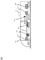
- FIG. It is a figure which shows an example of a structure of the rail vehicle in Example 1.
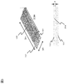
- FIG. It is a figure which shows the cross section and plane of a structure (noise canceller) which suppress the electromagnetic noise propagation of the cable and signal wire
- FIG. It is a figure which shows the model structure used for the electromagnetic field analysis. It is a figure which shows an electromagnetic field analysis result. It is a schematic diagram which shows an example of the structure which has arrange
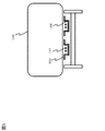
- FIG. 10 is a schematic diagram when a noise canceller is provided in an automobile in Example 7.
- FIG. 1 schematically shows an example of the configuration of a railway vehicle in the present embodiment.
- the railway vehicle 100 includes a pantograph 101, a power converter 102, a transponder 105 (communication device), and an electronic device 106.
- the pantograph 101 is supplied with electric power from an overhead line (not shown) and supplies electric power to an electronic device such as the power converter 102 through a signal line.
- the power converter 102 converts the voltage and frequency of the electric power received from the pantograph 101 and supplies the electric power to a motor (not shown).
- the transponder 105 transmits and receives signals wirelessly with a ground unit installed on the ground and an external communication device.
- the electronic devices 106 mounted on the railway vehicle including the pantograph 101, the power converter 102, and the transponder 105 are electrically connected by a signal line 107 (wiring).
- the signal line 107 is provided across the vehicles. Therefore, noise generated from one electronic device or the power converter 102 propagates through the signal line 107 and may affect other electronic devices across vehicles.
- the electromagnetic noise 104 generated from the power converter 102 is electromagnetically coupled to the surface of the conductive railway vehicle connected to the signal line 107 and the GND, so that the signal line 107 and propagates to the transponder 105, which may cause a malfunction in transmission / reception of the signal of the transponder 105.
- a filter circuit element such as a ferrite core is provided in each signal line in order to suppress noise generated from a noise source from propagating through the signal line.
- these filter circuit elements need to be provided for each signal line, in the case of a railway vehicle having several tens or more signal lines, an increase in labor for providing the filter circuit elements, and an increase in the number of filter circuit elements in the vehicle. There are problems such as an increase in weight and manufacturing cost.
- the present invention provides an EBG (Electromagnetic Band Gap) on the surface of a guide (signal line guide portion) that guides a signal line in a section of the signal line that connects a noise source and a device that receives noise.
- EBG Electromagnetic Band Gap
- the periodic conductor 103 (EBG structure) based on the principle is provided. Since the railway vehicle is a metal casing and the guide is also conductive, the guide is grounded to the ground via the railway vehicle, wheels, and tracks. Therefore, the periodic conductor 103 is installed on the surface of the conductive casing having the ground.
- the electromagnetic noise propagating through the signal line by electromagnetic coupling between the signal line and the railcar surface is attenuated by the periodic conductor 103 having the EBG structure, and the influence of the noise on the equipment connected by the signal line is suppressed.
- the same effect can be obtained even if there are a plurality of signal lines. Therefore, a plurality of periodic conductors 103 having the EBG structure are installed on the surface of a railway vehicle close to the provided signal line, for example, the surface of a guide, for example, without installing a ferrite core or the like on each signal line. Electromagnetic noise propagating through each signal line can be suppressed.
- the periodic conductor 103 provided in the guide is provided in a vehicle different from a vehicle having an electronic device serving as a noise source.
- the periodic conductor 103 may be provided in a vehicle having an electronic device serving as a noise source. It goes without saying that the effects of Even when the noise source and the electronic device affected by the noise are in the same vehicle, the same effect can be obtained by providing the periodic conductor 103 on the signal line between the noise source and the electronic device.
- the guide having the periodic conductor 103 plays a role as a noise canceller.
- the periodic conductor 103 can serve as a noise canceller even if it is provided directly on the railway vehicle.
- the noise canceller is grounded near a noise source such as an inverter, it is possible to suppress the propagation of noise before the noise propagates far away.
- FIG. 2 shows a sectional view and a plan view of a structure (noise canceller) for suppressing electromagnetic noise propagation of cables and signal lines according to an embodiment of the present invention.
- the noise canceller in this embodiment includes a periodic conductor 103 installed between a signal line 107 laid inside the conductive casing 101 and a surface inside the conductive casing 101.
- the periodic conductor 103 has a structure in which conductors having a predetermined shape are periodically arranged in a matrix.
- the conductors of the predetermined shape referred to here are periodically arranged in a matrix form, not only those arranged in a complete periodic manner but also some positions at the positions of the individual conductors of the predetermined shape. Even if there is a discrepancy, it includes those that play the role of noise cancellers.
- the conductive housing having the signal lines and the signal lines shown in FIG. 2 for example, the railway vehicle itself, a guide in the railway vehicle, and a signal line laid inside the railway vehicle are applicable. Note that this embodiment is not limited to railway vehicles or guides, and may be used for mobile objects such as cars and medical devices as long as signal lines are provided near the surface of the conductive housing. Can be applied. In addition, as a material of the conductive casing, a metal, a conductive resin, or the like can be considered.
- signal lines in a railway vehicle such as a power cable that transmits power from the power source to each device, and a signal cable that transmits signals from the signal source to each device. It is laid.
- the signal line 107 is used to send power and signals to each device as described above.
- the power and signal are sent by a current flowing through the signal line 107 and a voltage applied to the signal line 107.
- a magnetic field 202 and an electric field 201 are generated between the signal line 107 and the conductive casing 101 by the current and voltage flowing through the signal line 107.
- the phenomenon that current and voltage pass through the signal line is considered that the magnetic field 202 and the electric field 201 generated between the signal line 107 and the conductive casing 101 are propagated along the signal line 107. It is done. This becomes a factor of noise propagation.
- the periodic conductor 103 having an EBG structure is provided between the signal line 107 and the conductive casing 101.
- the periodic conductor 103 can attenuate an electric field having a specific frequency incident in a direction perpendicular to the installation surface of the periodic conductor 103.
- the conductor surface provided with the periodic conductor 103 is grounded (GND).
- mushroom-shaped conductors are arranged in a matrix so that the EBG structure attenuates the frequency of specific electromagnetic noise propagating due to the signal line.
- the periodic conductor 103 having an EBG structure is installed between the signal line 107 and the surface of the conductive casing 101 and on the surface of the conductive casing 101 on the signal line 107 side.
- the periodic conductor 103 functions as a noise canceller that absorbs electromagnetic noise energy propagating through the signal line and suppresses noise propagation through the signal line.
- a protective member for protecting the periodic conductor 103 may be provided on the surface of the periodic conductor 103.
- the protective member an insulating resin, an oxide such as aluminum, or the like may be used. Thereby, the periodic conductor 103 can be protected and durability can be improved.
- the distribution of the electric field 201 around the signal line 107 is complicated.
- the electric field 201 on the surface of the conductive casing is incident in a direction substantially perpendicular to the surface of the conductive casing 101.
- the magnetic field 202 is perpendicular to the direction of the electric field shown in FIG. 2 and is generated so as to cover the periphery of the signal line 107.
- the periodic conductor 103 is installed on the surface of the conductive casing 101 that is grounded, so that it absorbs the energy of the electric field of a specific frequency that is incident vertically and suppresses the propagation of noise that is propagated due to the signal line 107.
- the noise propagation suppression frequency fr is determined by an inductance Lc due to the shape of each conductor of the periodic conductor 103 and a parasitic capacitance Cd between adjacent conductors, as shown in Equation 1.
- the shape and structure of the periodic conductor 103 are adjusted, or a circuit element 104 such as a chip capacitor is used to set the capacitance Cd between the periodic conductors to a desired value. It may be used.
- the circuit element 104 having a desired capacitance Cd the frequency at which electromagnetic noise is absorbed can be easily controlled without changing the shape of the periodic conductor 103.
- the unit structure of the EBG structure in the periodic conductor 103 employs a mushroom-type structure having a substantially flat head and a substantially rod-like shape that supports the head. It is better to change the shape according to the frequency.
- FIG. 3 shows a model structure used for electromagnetic field analysis.
- the size of the surface on which the periodic conductor 103 is installed has a length of 2.5 m in the extending direction of the signal line 107 and a width of 1 m in the direction perpendicular to the extending direction. did.
- the distance between the signal line 107 and the periodic conductor 103 was 50 mm.
- each conductor was set to a width of 100 mm, a length of 50 mm, a conductor height of 10 mm, and a conductor thickness of 5 mm so that the frequency for absorbing electromagnetic noise was 3.3 MHz.
- the distance between adjacent individual conductors was set to 5 mm.
- the signal line laid above the periodic conductor 103 has a length of 3 m, and in the electromagnetic field analysis, electromagnetic noise is input from one end of the signal line 107 and the electromagnetic noise that is output from the other end and the electromagnetic noise that is input to the other end.
- the high-frequency propagation characteristics were obtained from the ratio.
- the conductive casing 101 is set to GND, the width is 1 m, the thickness is 10 mm, and the length is 3 m, which is the same as the signal line.
- Fig. 4 shows the electromagnetic field analysis results.
- the attenuation amount of the high frequency component propagating through the signal line 107 is rapidly increased only by about 3.3 MHz. This indicates that 3.3 MHz noise propagation is absorbed by the noise canceller according to the present embodiment.
- the amount of noise attenuation is the length and width of the surface on which the periodic conductor 103 is installed, the shape and structure of the periodic conductor 103, the distance between the individual periodic conductors 103, and the distance of the signal line 107 passing over the periodic conductor 103. It changes by etc.
- the attenuation amount of noise propagation can be increased. Assuming a railway vehicle, since the cable signal line in the vehicle extends to several tens of meters, the installation length of the 2.5 m periodic conductor 103 is sufficiently within the practical range.
- the extending direction of the signal line 107 and the direction of the periodicity of the structure of the periodic conductor 103 are matched.
- the present invention is not limited to this. The effect of the present invention can be obtained even if the direction in which the conductors are periodically arranged does not match.
- the periodic conductor 103 is assumed to be manufactured by a printed circuit board manufacturing process, but is not limited thereto.
- the individual conductors of the periodic conductor 103 may be manufactured by sheet metal processing or the like, and fixed to the conductive housing with screws or the like, so that the structure can be freely attached and detached. Electrical characteristics such as frequency for suppressing noise propagation are determined by the structure and interval of the periodic conductor 103.
- the structure of the periodic conductor 103 and the position of the periodic conductor 103 can be changed after mounting.
- the frequency for suppressing noise propagation can be adjusted.
- the height adjustment mechanism is not limited to a structure using screws, but may be any mechanism that can adjust the height, such as a structure that can be freely adjusted by a fitting type.
- FIG. 5 is a schematic view of a signal line passing through a guide 500 (signal line guide part) under the railcar floor. 5 shows an example in which a guide is provided outside the railway vehicle housing 100, the guide 500 may be provided in the railway vehicle housing 100.
- a conductive guide 500 for holding the signal line 107 under the floor of the railway vehicle casing 100.
- a noise canceller that can easily suppress electromagnetic noise propagating through a signal line, and a railway vehicle including the noise canceller.
- FIG. 6 is a diagram in the case where two signal lines 107 are provided on the upper side of the periodic conductor 103.
- the structure of the periodic conductor 103 may be the same.
- the separation part 601 for separating the electromagnetic coupling of the periodic conductor 103 is provided.
- the separation unit 601 is configured so that the circuit element is in a region between the signal lines 107 that are separated from each other by a predetermined distance. It can be configured by providing a portion where 104 is not mounted.
- the separation unit 601 can be configured by changing only a part of the interconductor distance for the periodic conductor 103. That is, the separation part 601 may be a non-periodic part as a region different from the periodicity of the periodic conductor 103.
- the separation unit 601 is provided in the vicinity of the center of the periodic conductor 103 between the signal lines.
- the present invention is not limited to this, and the positional relationship between the signal lines and the signal lines and the structure thereof are not limited thereto. Due to this limitation, it may be provided close to one of the signal lines. That is, the separation unit 601 may be provided so as to achieve the electromagnetic noise attenuation required for each signal line.
- the extending direction of the separation unit 601 and the extending direction of the signal line 107 are matched, but the present invention is not limited to this. That is, in order to prevent the electromagnetic coupling between each signal line and the periodic conductor 103 from affecting each other, a separation unit 601 that makes the periodic conductor 103 non-periodic is provided in a region between each signal line 107. That's fine.
- FIG. 7 shows a structure in which the periodic conductor 103 is provided on each surface of the conductive casing 701 covering the periphery of two signal lines arranged at a predetermined distance. Although not shown, the conductive casing 701 is grounded.
- the structure in which the periodic conductor 103 is provided on one surface of the planar conductive casing 501 located in the vicinity of the signal line 107 is shown.
- the shape of the conductive casing 501 in the vicinity of the signal line 107 is a shape surrounding the signal line 107 as shown in FIG. 7, the periodic conductor 103 for suppressing noise propagation is included in the conductive casing 701. It is desirable to provide the periodic conductor 103 on all of the surfaces on the signal line 107 side.
- the signal line 107 is surrounded by the conductive casing 701 as shown in FIG. 7, and the surface of the conductive casing 701 that is electromagnetically coupled to the signal line 107 cannot be limited to a single plane. This is because the electric field distribution between the signal line 107 and the conductive casing 701 can be considered to be generated between each surface of the conductive casing 701 surrounding the signal line 107.
- the periodic conductor 103 may be provided on each surface of the conductive casing 701 that is electromagnetically coupled to the signal line 107.
- the electric field distribution generated from the signal line 107 is incident in a direction substantially perpendicular to the surface of the periodic conductor 103, so that the attenuation effect of electromagnetic noise propagating through the signal line 107 can be enhanced.
- the separation portion 601 in the conductive casing 501 when there are a plurality of signal lines 107 for which noise propagation is to be suppressed, it is desirable to provide the separation portion 601 in the conductive casing 501 as described in the second embodiment. Therefore, in the case of FIG. 7, it is desirable to provide the separation portion 601 on the upper surface of the signal line in addition to the lower surface of the signal line closer to the signal line 107. In addition, it is preferable to provide the separating portion 601 between the periodic conductor 103 provided on each surface of the conductive casing 701. Thereby, the electromagnetic noise which propagates through each signal line can be attenuated, respectively.
- the shape of the conductive casing 701 is not limited to this, and for example, the shape of the upper surface of the signal line 107 is not surrounded as shown in FIG. It is also possible to do this. In that case, a high noise reduction effect can be obtained by providing the periodic conductor 103 for suppressing noise propagation on both the lower surface and the side surface. Thereby, the signal line laying structure which suppressed noise propagation can be provided.
- the periodic conductor 103 is provided on those surfaces, thereby reducing the electronic noise propagating through the signal line. Can be increased.
- the signal line 107 is a single line.
- the case where the signal line bundle 802 and 803 includes a plurality of signal lines 107 is described with reference to FIG. .
- FIG. 8 is an example showing a structure in the case where the signal line bundles 802 and 803 are housed in a U-shaped conductive casing 801.
- the method of bundling the signal lines is not limited to the signal line bundles 802 and 803 shown in FIG. 8, and any bundling method may be used as long as the signal lines are bundled.
- the electric field distribution generated from the signal line bundles 802 and 803 is omitted, but the electric field distribution is incident substantially perpendicular to the surface of the periodic conductor 103.
- the common mode noise propagates between the shield sheath of the shielded cable and the conductive casing, and therefore the periodic conductor 103 for suppressing noise propagation is electrically connected to the shielded cable.
- the effect of reducing noise propagation can be obtained by installing it between the conductive casing 801. Thereby, the noise propagation suppression structure which suppressed noise propagation can be provided.
- propagation of electromagnetic noise in a bundle of signal lines can be suppressed even when a plurality of signal lines are bundled.
- FIG. 9 shows an example of the structure of the noise canceller in the present embodiment.
- Example 4 shows a structure in which the periodic conductor 103 is provided between the shielded cable and the conductive casing 801 in order to reduce common mode noise even if the signal line bundles 801 and 802 are shielded cables.
- the structure of this embodiment can also reduce the normal mode electromagnetic field that propagates between the inner conductor 901 that is the core of the cable and the outer conductor 902 that is the shield in the shielded cable.
- a periodic conductor 903 for suppressing noise propagation is provided between the inner conductor 901 and the outer conductor 902. That is, the periodic conductor 903 is provided with a gap 904 so as to cover the periphery of the internal conductor 901 in the extending direction. In this case, the electric field distribution generated from the inner conductor 901 enters the surface of the periodic conductor 903 in a substantially vertical direction. Thereby, the periodic conductor 903 can suppress noise propagation of a specific frequency.
- the surface parallel to the outer conductor 902 is curved to be a curved surface, but may be a flat surface instead of a curved surface.
- FIG. 10 is an example showing the structure of the noise canceller in the present embodiment.
- FIG. 10 shows an example in which a shielded cable 1005 having a signal line 1004 therein is covered with a shielding conductor 1001 having a periodic conductor 903. At this time, the shielding conductor 1001 is preferably grounded. Even if the target signal line is a single line or a shielded cable, the effect of reducing noise propagation can be obtained.
- the shielding conductor 1001 has a structure that can be opened and closed by providing an opening / closing part 1002 (fixed part) that allows one end and the other end of the shielding conductor 1001 to be freely attached and detached.
- the noise canceller according to the present embodiment can be applied later as a noise propagation suppression measure.
- the opening / closing part 1002 can be realized at low cost by using fasteners, hooks, buttons, and the like.
- the shielding conductor 1001 may be a flexible plate-like member such as a thin metal plate or a conductive flexible substrate sheet. Thereby, the electromagnetic noise countermeasure of a signal line can be retrofitted at low cost.
- a noise canceller that can be retrofitted can be provided as a countermeasure for suppressing the electromagnetic noise propagation of the signal line.
- FIG. 11 shows a schematic diagram when a noise canceller is provided in an automobile.
- the automobile includes an automobile housing 1100 including a chassis and a body, an electronic device 1101 such as a battery, a power converter 1102, a periodic conductor 1103, and a signal line 1107.
- an electronic device 1101 such as a battery
- a power converter 1102 a periodic conductor 1103, and a signal line 1107.
- electronic devices that generate electromagnetic noise such as the power converter 1102 and electromagnetic noise that propagates through the signal line 1107 that connects the electronic device 1101 can be suppressed by providing the automobile casing 1100 with the periodic conductor 1103.
- the place where the periodic conductor 1103 is provided is not limited to the automobile housing 1100, and the same effect can be obtained even if it is provided in a guide for bundling the signal lines.
- the present invention is not limited to these.
- the noise canceller according to the present invention can be applied to any device such as a medical device in which a power source and an electronic device and a number of signal lines connecting them are housed in a conductive casing.
- the present invention is not limited to the above-described embodiments, and includes various modifications.
- the above-described embodiments have been described in detail for easy understanding of the present invention, and are not necessarily limited to those having all the configurations described.
- a part of the configuration of one embodiment can be replaced with the configuration of another embodiment, and the configuration of another embodiment can be added to the configuration of one embodiment.
- SYMBOLS 100 Rail vehicle, 101 ... Pantograph, 102 ... Power converter, 103 ... Periodic conductor, 105 transponder, 106 ... Electronic equipment, 107 ... Signal line, 204 ... Circuit element, 500 ... Guide, 601 ... Separation part, 701 ... Housing , 801 ... Housing, 802 ... Signal line bundle, 803 ... Signal line bundle, 901 ... Signal line internal conductor, 902 ... Signal line external conductor, 903 ... Periodic conductor, 1001 ... Shielding conductor, 1002 ... Opening / closing section, 1004 ... Signal line , 1005 ... shielded cable
Landscapes
- Engineering & Computer Science (AREA)
- Automation & Control Theory (AREA)
- Transportation (AREA)
- Mechanical Engineering (AREA)
- Microelectronics & Electronic Packaging (AREA)
- Shielding Devices Or Components To Electric Or Magnetic Fields (AREA)
- Electric Propulsion And Braking For Vehicles (AREA)
- Noise Elimination (AREA)
Abstract
L'invention concerne un dispositif de suppression de bruit pour supprimer la propagation de bruit en raison d'une ligne de signal, et un véhicule ferroviaire et une automobile où le dispositif de suppression de bruit est monté. Le dispositif de suppression de bruit comporte un convertisseur de puissance électrique qui commande un moteur électrique par entraînement, un dispositif de communication pour établir une communication avec l'extérieur, une ligne de signal disposée entre le convertisseur de puissance électrique et le dispositif de communication, et une unité de guidage de ligne de signal conductrice qui guide une section prédéterminée de la ligne de signal, et caractérisé en ce que l'unité de guidage de ligne de signal est connectée électriquement à la terre et comprend une structure EBG dans laquelle un conducteur ayant une forme prédéterminée est disposé périodiquement dans une matrice, la structure EBG étant disposée sur une face côté ligne de signal de l'unité de guidage de ligne de signal entre la ligne de signal et la face de l'unité de guidage de ligne de signal.
Priority Applications (2)
| Application Number | Priority Date | Filing Date | Title |
|---|---|---|---|
| PCT/JP2016/055965 WO2017149578A1 (fr) | 2016-02-29 | 2016-02-29 | Dispositif de suppression de bruit, véhicule ferroviaire et automobile |
| JP2016563146A JP6337143B2 (ja) | 2016-02-29 | 2016-02-29 | 鉄道車両 |
Applications Claiming Priority (1)
| Application Number | Priority Date | Filing Date | Title |
|---|---|---|---|
| PCT/JP2016/055965 WO2017149578A1 (fr) | 2016-02-29 | 2016-02-29 | Dispositif de suppression de bruit, véhicule ferroviaire et automobile |
Publications (1)
| Publication Number | Publication Date |
|---|---|
| WO2017149578A1 true WO2017149578A1 (fr) | 2017-09-08 |
Family
ID=59742609
Family Applications (1)
| Application Number | Title | Priority Date | Filing Date |
|---|---|---|---|
| PCT/JP2016/055965 Ceased WO2017149578A1 (fr) | 2016-02-29 | 2016-02-29 | Dispositif de suppression de bruit, véhicule ferroviaire et automobile |
Country Status (2)
| Country | Link |
|---|---|
| JP (1) | JP6337143B2 (fr) |
| WO (1) | WO2017149578A1 (fr) |
Citations (10)
| Publication number | Priority date | Publication date | Assignee | Title |
|---|---|---|---|---|
| JPS5628802Y2 (fr) * | 1976-09-22 | 1981-07-09 | ||
| JPH0343758Y2 (fr) * | 1985-09-26 | 1991-09-12 | ||
| JPH0515586B2 (fr) * | 1986-06-20 | 1993-03-02 | Hitachi Ltd | |
| JPH0730501U (ja) * | 1993-11-05 | 1995-06-06 | 株式会社ユタカ製作所 | 鉄道車両用高電圧大電流配線の電磁波シールド装置 |
| JPH0727761Y2 (ja) * | 1989-09-27 | 1995-06-21 | 東海旅客鉄道株式会社 | ディーゼル動車の制御盤 |
| JP2002159124A (ja) * | 2000-11-17 | 2002-05-31 | Toshiba Transport Eng Inc | 車両用電線クリート |
| JP2006168534A (ja) * | 2004-12-16 | 2006-06-29 | Toshiba Corp | 車両制御装置及びそれを用いた鉄道車両 |
| JP2013232613A (ja) * | 2012-04-05 | 2013-11-14 | Sony Corp | 配線基板及び電子機器 |
| JP2015097273A (ja) * | 2014-12-12 | 2015-05-21 | 株式会社東芝 | 回路基板および半導体部品 |
| JP2016032081A (ja) * | 2014-07-30 | 2016-03-07 | 公益財団法人鉄道総合技術研究所 | 電磁波遮蔽材及び機器収容体 |
-
2016
- 2016-02-29 JP JP2016563146A patent/JP6337143B2/ja active Active
- 2016-02-29 WO PCT/JP2016/055965 patent/WO2017149578A1/fr not_active Ceased
Patent Citations (10)
| Publication number | Priority date | Publication date | Assignee | Title |
|---|---|---|---|---|
| JPS5628802Y2 (fr) * | 1976-09-22 | 1981-07-09 | ||
| JPH0343758Y2 (fr) * | 1985-09-26 | 1991-09-12 | ||
| JPH0515586B2 (fr) * | 1986-06-20 | 1993-03-02 | Hitachi Ltd | |
| JPH0727761Y2 (ja) * | 1989-09-27 | 1995-06-21 | 東海旅客鉄道株式会社 | ディーゼル動車の制御盤 |
| JPH0730501U (ja) * | 1993-11-05 | 1995-06-06 | 株式会社ユタカ製作所 | 鉄道車両用高電圧大電流配線の電磁波シールド装置 |
| JP2002159124A (ja) * | 2000-11-17 | 2002-05-31 | Toshiba Transport Eng Inc | 車両用電線クリート |
| JP2006168534A (ja) * | 2004-12-16 | 2006-06-29 | Toshiba Corp | 車両制御装置及びそれを用いた鉄道車両 |
| JP2013232613A (ja) * | 2012-04-05 | 2013-11-14 | Sony Corp | 配線基板及び電子機器 |
| JP2016032081A (ja) * | 2014-07-30 | 2016-03-07 | 公益財団法人鉄道総合技術研究所 | 電磁波遮蔽材及び機器収容体 |
| JP2015097273A (ja) * | 2014-12-12 | 2015-05-21 | 株式会社東芝 | 回路基板および半導体部品 |
Also Published As
| Publication number | Publication date |
|---|---|
| JPWO2017149578A1 (ja) | 2018-03-08 |
| JP6337143B2 (ja) | 2018-06-06 |
Similar Documents
| Publication | Publication Date | Title |
|---|---|---|
| JP2013214705A (ja) | 櫛歯構造のシールド層及びそのワイヤレス充電トランスミッター | |
| JP5868285B2 (ja) | プリント基板 | |
| JPWO2018173263A1 (ja) | 回路基板 | |
| JP5686090B2 (ja) | ノイズフィルタが搭載された電子装置 | |
| JP6337143B2 (ja) | 鉄道車両 | |
| US9039430B2 (en) | Electric connector, train-information transmission/reception system, and method for connecting electric connector | |
| CN208142474U (zh) | 高压插接连接器 | |
| US20160207635A1 (en) | Transport machine and aircraft | |
| JP2008181818A (ja) | 信号伝送ケーブル接続構造 | |
| US20200139905A1 (en) | Cable connection structure | |
| WO2018012144A1 (fr) | Dispositif de conversion de puissance pour véhicule ferroviaire, et véhicule ferroviaire | |
| Zhao et al. | Anti-electromagnetic interference design for railway vehicles in complex electromagnetic environment | |
| CN218400294U (zh) | 电动座椅驱动传输装置及包括其的电动座椅总成、车辆 | |
| US12526913B2 (en) | Electronic device | |
| JP2020181843A (ja) | 電子制御装置 | |
| JPH08148877A (ja) | 電子機器用遮蔽装置 | |
| JP7239870B2 (ja) | 電磁波遮蔽装置 | |
| JP2007088332A (ja) | Emcシールドケース | |
| Wu et al. | Design and Test of Anti-EMI for Rail Trains | |
| JP2014138130A (ja) | 電線の配線システム | |
| US12388359B2 (en) | Power conversion device | |
| KR102871708B1 (ko) | 모터 제어 유닛 | |
| JP7607846B2 (ja) | 鉄道車両用の電力変換装置 | |
| JP7439490B2 (ja) | ノイズ対策回路 | |
| JP2009022142A (ja) | 列車情報送受信システム |
Legal Events
| Date | Code | Title | Description |
|---|---|---|---|
| ENP | Entry into the national phase |
Ref document number: 2016563146 Country of ref document: JP Kind code of ref document: A |
|
| NENP | Non-entry into the national phase |
Ref country code: DE |
|
| 121 | Ep: the epo has been informed by wipo that ep was designated in this application |
Ref document number: 16892423 Country of ref document: EP Kind code of ref document: A1 |
|
| 122 | Ep: pct application non-entry in european phase |
Ref document number: 16892423 Country of ref document: EP Kind code of ref document: A1 |