WO2017149669A1 - Appareil de ventilation - Google Patents
Appareil de ventilation Download PDFInfo
- Publication number
- WO2017149669A1 WO2017149669A1 PCT/JP2016/056287 JP2016056287W WO2017149669A1 WO 2017149669 A1 WO2017149669 A1 WO 2017149669A1 JP 2016056287 W JP2016056287 W JP 2016056287W WO 2017149669 A1 WO2017149669 A1 WO 2017149669A1
- Authority
- WO
- WIPO (PCT)
- Prior art keywords
- frame
- ventilation fan
- flange portion
- oblique
- guide holes
- Prior art date
- Legal status (The legal status is an assumption and is not a legal conclusion. Google has not performed a legal analysis and makes no representation as to the accuracy of the status listed.)
- Ceased
Links
Images


Classifications
-
- F—MECHANICAL ENGINEERING; LIGHTING; HEATING; WEAPONS; BLASTING
- F24—HEATING; RANGES; VENTILATING
- F24F—AIR-CONDITIONING; AIR-HUMIDIFICATION; VENTILATION; USE OF AIR CURRENTS FOR SCREENING
- F24F7/00—Ventilation
- F24F7/04—Ventilation with ducting systems, e.g. by double walls; with natural circulation
- F24F7/06—Ventilation with ducting systems, e.g. by double walls; with natural circulation with forced air circulation, e.g. by fan positioning of a ventilator in or against a conduit
- F24F7/10—Ventilation with ducting systems, e.g. by double walls; with natural circulation with forced air circulation, e.g. by fan positioning of a ventilator in or against a conduit with air supply, or exhaust, through perforated wall, floor or ceiling
Definitions
- the present invention relates to a ventilation fan that sucks indoor air and exhausts it outdoors or sucks outdoor air and supplies it indoors.
- Patent Document 1 discloses a ventilation fan that includes a frame-shaped frame, an electric motor, an orifice, a fan, and a shutter, and is used by being attached to a ventilation opening.
- the ventilation fan is simply fixed by the mounting bolts, but when installing at a high place, there is concern about dropping during an earthquake, and so on, from the frame-shaped frame of the ventilation fan toward the indoor side wall surface. It is fixed by a wood screw using a screw fixing hole provided in a flange portion formed so as to be along.
- a wooden frame that is slightly larger than the frame shape of the ventilation fan on the site, and a large wooden frame that is larger than the frame-shaped frame within the range specified by the standard is applied to the contractor. Or it must be created by the end user.
- the range of the internal dimensions of the wooden frame defined by the standard is generally a range that is about 1 mm to 5 mm larger than the frame.
- the present invention has been made in view of the above, and an object of the present invention is to obtain a ventilation fan that can be easily fixed without the need for recreating a wooden frame.
- the present invention includes a fan inside a frame-shaped frame having an opening at the center, and the frame-shaped frame is mounted on a wooden frame installed in a ventilation fan mounting hole on a wall surface. It is a ventilation fan fixed in the inserted state.
- the frame-shaped frame has a cylindrical portion inserted into the wooden frame, and a flange portion extending from the indoor side end of the cylindrical portion so as to extend along the indoor side of the wall surface.
- a screw fixing hole perpendicular to the contact surface and a plurality of oblique screwing guide holes having an inclination with respect to the contact surface are provided.
- the plurality of oblique screwing guide holes are disposed on at least two opposite sides of the flange portion.
- the ventilating fan according to the present invention has an effect that it can be easily fixed without generating the trouble of recreating the wooden frame.
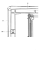
- FIG. Enlarged perspective view of the vicinity of the oblique screwing guide hole of the ventilation fan according to Embodiment 1 Sectional drawing of the part of the diagonal screwing guide hole of the ventilation fan which concerns on Embodiment 1
- FIG. 1 is an exploded perspective view of the ventilation fan according to Embodiment 1 of the present invention in an installed state.
- the ventilation fan 1 includes a frame-shaped frame 2 having an open center, and an electric motor 3 fixed inside the frame-shaped frame 2.
- an orifice 4 is provided in a frame-like frame 2, and an oil receiver 5 is attached to the orifice 4.
- An electric motor 3 is provided inside the frame-shaped frame 2, a fan 7 is attached to the shaft 6 of the electric motor 3, and a spinner 8 is attached to the center of the fan 7. That is, the fan 7 is installed inside the frame-like frame 2.
- the ventilation fan 1 is fixed to a wooden frame 11 or the like inserted into a ventilation fan mounting hole 10 formed on the wall surface of the building, and the fan 7 is driven to rotate, so that the indoor air and the outdoor air are interposed. Create an air flow and ventilate the room. That is, the ventilation fan 1 is fixed in a state where the frame-shaped frame 2 is inserted into the ventilation fan mounting hole 10 on the wall surface on which the wooden frame 11 is installed.
- the frame-shaped frame 2 has a strength to support the entire ventilation fan 1 and is formed in a rectangular shape with resin.
- the frame-like frame 2 is open at the indoor side and the outdoor side.
- the frame-like frame 2 is not limited to the shape described above.
- the shape may be a circular shape, and the material may be a metal steel plate.
- the orifice 4 is detachably provided on the indoor side of the frame-like frame 2, that is, on the air inflow side.
- the orifice 4 functions as a wind tunnel that closes a gap between the frame-shaped frame 2 and the fan 7 and guides indoor air to the fan 7.
- the orifice 4 is made of synthetic resin or metal and has a filter or mesh guard attached thereto, but the filter or mesh guard is not shown in FIG.
- the oil receiver 5 is detachably attached to the orifice 4.
- the oil receiver 5 has a function of collecting oil contained in oil smoke discharged during cooking on the orifice 4 and collecting the oil flowing down through the orifice 4.
- the oil receiver 5 may be integrated with the orifice 4.
- a plurality of shutter plates 9 for opening and closing the outdoor opening are provided on the outdoor side of the frame-like frame 2.
- the shutter plate 9 is made of resin.
- the shutter plate 9 pivots up and down by the wind pressure of the ventilation flow generated by the fan 7 and opens to the side when the fan 7 stops. close. Since the shutter plate 9 closes the air path, the movement of the air inside and outside the room is suppressed when the ventilation fan 1 is stopped, so that the room temperature can be stabilized.
- the electric motor 3 rotates the shaft 6 provided on the electric motor 3 to rotate the fan 7 attached to the shaft 6.
- the spinner 8 is detachably fitted to the shaft 6, and the indoor air and the outdoor air of the frame-like frame 2 are ventilated in a state where the ventilation fan 1 is fixed.
- FIG. 2 is a perspective view of the frame-shaped frame of the ventilation fan according to the first embodiment.
- the frame-like frame 2 has a cylindrical portion 2 a that is inserted into the wooden frame 11.
- An upper flange portion 20 is provided at the upper edge portion, and a left flange portion 30 is provided at the left edge portion along the indoor side wall surface at the indoor side end of the cylindrical portion 2a.
- a right flange portion 40 is provided at the right edge portion, and a lower flange portion 50 is provided at the flange lower edge portion.
- the upper flange portion 20, the left flange portion 30, the right flange portion 40, and the lower flange portion 50 are collectively referred to as a flange portion 60.
- the cylinder part 2a and the flange part 60 are integrally molded. Since the outer shape of the flange portion 60 is larger than that of the ventilation fan mounting hole 10, the surface rising from the cylindrical portion 2 a comes into contact with the wooden frame 11 when the cylindrical portion 2 a is inserted into the wooden frame 11.
- the surface rising from the cylindrical portion 2a of the flange portion 60 is referred to as a contact surface 60a.
- the upper flange portion 20 is provided with a screw fixing hole 20a for fixing the ventilation fan 1 and an oblique screwing guide hole 20b.
- the left flange portion 30 is provided with a screw fixing hole 30a for fixing the ventilation fan 1 and an oblique screw driving guide hole 30b.
- the right flange portion 40 is provided with a screw fixing hole 40a for fixing the ventilation fan 1 and an oblique screwing guide hole 40b.
- the lower flange portion 50 is provided with a screw fixing hole 50a for fixing the ventilation fan 1 and an oblique screw driving guide hole 50b.
- the screw fixing holes 20a, 30a, 40a, 50a are perpendicular to the contact surface 60a, and the oblique screwing guide holes 20b, 30b, 40b, 50b are inclined with respect to the contact surface 60a with the wooden frame 11. Have.
- the created wooden frame 11 is inserted into the ventilation fan mounting hole 10 formed on the wall surface of the building, and the gap between the ventilation fan mounting hole 10 and the wooden frame 11 is filled with a caulking agent and fixed.
- the frame-like frame 2 is inserted into the wooden frame 11 fixed to the ventilation fan mounting hole 10 from the indoor side.
- the wooden frame 11 has a plate thickness of about 20 mm to 30 mm, and the dimensions inside the wooden frame are created on site by a contractor or end user within a range that is about 1 mm to 5 mm larger than the outer dimensions of the frame-like frame 2. . Therefore, the ventilation fan 1 cannot be fixed to the wall surface simply by inserting the frame-like frame 2 into the wooden frame 11.
- the screw fixing holes 20a provided in the flange portion 60 formed so as to extend from the upper, lower, left and right edges of the frame-like frame 2 of the ventilation fan 1 toward the indoor side wall surface A wood screw is driven into the wooden frame 11 by 30a, 40a, 50a.
- the ventilation fan 1 When the ventilation fan 1 is fixed to the wooden frame 11 prepared according to the recommended dimensions described in the installation manual or the instruction manual, the wood screw is driven into the wooden frame 11 from the screw fixing holes 20a, 30a, 40a, 50a. It can be made to contact firmly and the ventilation fan 1 can be fixed.
- the wooden frame 11 prepared at the work site is not prepared according to the recommended dimensions, and the wooden frame 11 is detached from the screw fixing holes 20a, 30a, 40a, 50a, and the wooden screw cannot be driven.
- the ventilation fan 1 is attached to one side, the wooden frame 11 is recreated, or the gap between the wooden frame 11 and the ventilation fan 1 is filled. Or the like. That is, even if the wooden frame 11 is not created according to the recommended dimensions, the ventilation fan 1 can be easily fixed by using the guide holes 20b, 30b, 40b, and 50b in the oblique screw.
- FIG. 3 is an enlarged perspective view of the vicinity of the oblique screwing guide hole of the ventilation fan according to the first embodiment.
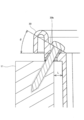
- FIG. 4 is a cross-sectional view of a portion of the oblique screw driving guide hole of the ventilation fan according to the first embodiment.
- the oblique screwing guide hole 30b will be described, but the same applies to the oblique screwing guide holes 20b, 40b, and 50b.
- the oblique screwing guide hole 30b is a square hole.
- the screwing angle ⁇ of the oblique screwing guide hole 30b by increasing the screwing angle ⁇ of the oblique screwing guide hole 30b, the guide for driving the wooden screw into the wooden frame 11 can be lengthened, and screwing can be performed more easily. Furthermore, the allowable gap width L with the wooden frame 11 can be increased.
- the screwing angle ⁇ is an inclination with respect to the contact surface 60a of the oblique screwing guide hole 30b, and the wood screw is screwed in a state inclined with respect to the wooden frame 11 as the screwing angle ⁇ increases.
- the ventilation fan 1 is attached to one side, the wooden frame 11 is recreated, The correspondence of filling the gap between the fan 11 and the ventilation fan 1 becomes unnecessary.
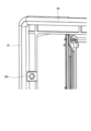
- FIG. FIG. 5 is an enlarged perspective view of the vicinity of the oblique screw driving guide hole of the ventilation fan according to Embodiment 2 of the present invention.
- the oblique screwing guide hole 30b is a round hole. If the oblique screwing guide hole 30b is a round hole, the structure of the mold for creating the frame-like frame 2 is somewhat complicated due to the addition of a slide or the like. Since the contact area between the wood screw and the oblique screw driving guide hole 30b increases, the wood screw can be driven easily.
- the oblique screwing guide hole 30b has been described, but the same applies to the oblique screwing guide holes 20b, 40b, and 50b.
- the upper flange portion 20, the left flange portion 30, the right flange portion 40, and the lower flange portion 50 are provided with the oblique screwing guide holes 20b, 30b, 40b, 50b.
- the oblique screwing guide holes 20b and 50b may be provided, or only the left and right oblique screwing guide holes 30b and 40b may be provided. That is, the oblique screwing guide holes 20b and 50b may be provided on the upper and lower sides of the flange portion 60, or the oblique screwing guide holes 30b and 40b may be provided on the left and right sides of the flange portion 60.
- the ventilation fan 1 can be attached to the wooden frame. 11 can be securely fixed to the center.
- the upper flange portion 20, the left flange portion 30, the right flange portion 40, and the lower flange portion 50 are provided with oblique screwing guide holes 20b, 30b, 40b, 50b one by one.
- the upper flange portion 20, the left flange portion 30, the right flange portion 40, and the lower flange portion 50 may be provided with a plurality of oblique screwing guide holes 20b, 30b, 40b, and 50b.
- an oblique screwing guide hole may be provided on the diagonal of the flange portion 60.
- the shutter plate 9 is opened and closed by the presence or absence of the wind pressure of the ventilation flow by the fan 7.
- the shutter plate 9 is connected to the opening and closing device by a connecting rod, and manually or automatically by the opening and closing device.
- a structure that can be opened and closed may be used.
- the shutter plate 9 can be made of a material other than resin.
- the shutter plate 9 can be made of a steel plate, but is not limited to this. Further, the shutter plate 9 may have a single structure.
- the configuration described in the above embodiment shows an example of the contents of the present invention, and can be combined with another known technique, and can be combined with other configurations without departing from the gist of the present invention. It is also possible to omit or change the part.
Landscapes
- Engineering & Computer Science (AREA)
- Chemical & Material Sciences (AREA)
- Combustion & Propulsion (AREA)
- Mechanical Engineering (AREA)
- General Engineering & Computer Science (AREA)
- Air-Flow Control Members (AREA)
Abstract
Cet appareil de ventilation comprend un ventilateur sur l'intérieur d'un cadre en forme de cadre (2) doté d'une ouverture au centre, et est fixé tandis que le cadre en forme de cadre (2) est inséré dans le cadre en bois installé dans un trou de montage d'appareil de ventilation dans une surface de paroi. Le cadre en forme de cadre (2) présente une partie tubulaire (2a) qui est insérée dans le cadre en bois et une partie de bride (60) qui s'étend de l'extrémité côté intérieur de la partie tubulaire (2a) le long du côté intérieur de la surface de paroi. La partie de bride (60) comprend des trous de fixation de vis (20a, 30a, 40a, 50a) qui sont perpendiculaires à la surface de butée (60a) en appui sur le cadre en bois et une pluralité de trous de guidage d'insertion de vis obliques (20b, 30b, 40b, 50b) qui sont inclinés par rapport à la surface de butée (60a). La pluralité de trous de guidage d'insertion de vis obliques (20b, 30b, 40b, 50b) sont disposés sur au moins deux surfaces opposées de la partie de bride (60).
Priority Applications (2)
| Application Number | Priority Date | Filing Date | Title |
|---|---|---|---|
| JP2018502917A JP6469308B2 (ja) | 2016-03-01 | 2016-03-01 | 換気扇 |
| PCT/JP2016/056287 WO2017149669A1 (fr) | 2016-03-01 | 2016-03-01 | Appareil de ventilation |
Applications Claiming Priority (1)
| Application Number | Priority Date | Filing Date | Title |
|---|---|---|---|
| PCT/JP2016/056287 WO2017149669A1 (fr) | 2016-03-01 | 2016-03-01 | Appareil de ventilation |
Publications (1)
| Publication Number | Publication Date |
|---|---|
| WO2017149669A1 true WO2017149669A1 (fr) | 2017-09-08 |
Family
ID=59743577
Family Applications (1)
| Application Number | Title | Priority Date | Filing Date |
|---|---|---|---|
| PCT/JP2016/056287 Ceased WO2017149669A1 (fr) | 2016-03-01 | 2016-03-01 | Appareil de ventilation |
Country Status (2)
| Country | Link |
|---|---|
| JP (1) | JP6469308B2 (fr) |
| WO (1) | WO2017149669A1 (fr) |
Citations (8)
| Publication number | Priority date | Publication date | Assignee | Title |
|---|---|---|---|---|
| JPS5031752U (fr) * | 1973-07-17 | 1975-04-08 | ||
| JPS6012123U (ja) * | 1983-07-04 | 1985-01-26 | 三菱電機株式会社 | 換気扇 |
| JPS60169871U (ja) * | 1984-04-18 | 1985-11-11 | 富士通電装株式会社 | ラツクの表面板固着構造 |
| JPH05126374A (ja) * | 1991-11-08 | 1993-05-21 | Matsushita Seiko Co Ltd | 換気扇 |
| JPH0680180U (ja) * | 1993-04-26 | 1994-11-08 | 特殊木化工業株式会社 | 電力量計用取付板 |
| JP2005188772A (ja) * | 2003-12-24 | 2005-07-14 | Fukuvi Chem Ind Co Ltd | 換気フードおよび換気フードの取付方法 |
| JP2006141188A (ja) * | 2004-11-09 | 2006-06-01 | Takaden Akita:Kk | 埋込型分電盤 |
| JP2008121954A (ja) * | 2006-11-10 | 2008-05-29 | Mirai Ind Co Ltd | 換気扇固定台座 |
Family Cites Families (1)
| Publication number | Priority date | Publication date | Assignee | Title |
|---|---|---|---|---|
| JP3708361B2 (ja) * | 1999-04-23 | 2005-10-19 | 松下エコシステムズ株式会社 | 換気扇 |
-
2016
- 2016-03-01 WO PCT/JP2016/056287 patent/WO2017149669A1/fr not_active Ceased
- 2016-03-01 JP JP2018502917A patent/JP6469308B2/ja active Active
Patent Citations (8)
| Publication number | Priority date | Publication date | Assignee | Title |
|---|---|---|---|---|
| JPS5031752U (fr) * | 1973-07-17 | 1975-04-08 | ||
| JPS6012123U (ja) * | 1983-07-04 | 1985-01-26 | 三菱電機株式会社 | 換気扇 |
| JPS60169871U (ja) * | 1984-04-18 | 1985-11-11 | 富士通電装株式会社 | ラツクの表面板固着構造 |
| JPH05126374A (ja) * | 1991-11-08 | 1993-05-21 | Matsushita Seiko Co Ltd | 換気扇 |
| JPH0680180U (ja) * | 1993-04-26 | 1994-11-08 | 特殊木化工業株式会社 | 電力量計用取付板 |
| JP2005188772A (ja) * | 2003-12-24 | 2005-07-14 | Fukuvi Chem Ind Co Ltd | 換気フードおよび換気フードの取付方法 |
| JP2006141188A (ja) * | 2004-11-09 | 2006-06-01 | Takaden Akita:Kk | 埋込型分電盤 |
| JP2008121954A (ja) * | 2006-11-10 | 2008-05-29 | Mirai Ind Co Ltd | 換気扇固定台座 |
Also Published As
| Publication number | Publication date |
|---|---|
| JP6469308B2 (ja) | 2019-02-13 |
| JPWO2017149669A1 (ja) | 2018-06-28 |
Similar Documents
| Publication | Publication Date | Title |
|---|---|---|
| JP5249892B2 (ja) | パネル装置 | |
| KR20090046344A (ko) | 방충망이 구비된 시스템 루버 | |
| JP6469308B2 (ja) | 換気扇 | |
| US20240280278A1 (en) | Embedded ventilation fan | |
| JP6772361B2 (ja) | 天井パネルおよび空気調和機 | |
| JP2018021739A (ja) | 換気扇 | |
| JP4811052B2 (ja) | 外壁端末換気口 | |
| WO2017158834A1 (fr) | Ventilateur soufflant | |
| JP6434151B2 (ja) | 換気扇 | |
| JP3913741B2 (ja) | 多角形窓用コーナー部品、コーナー部品を備えた多角形窓 | |
| WO2022219812A1 (fr) | Ventilateur soufflant | |
| US5746654A (en) | Ventilator | |
| JPH09170775A (ja) | 天井埋込み形空気調和機 | |
| JP2005232872A (ja) | ガラリ取り付け構造 | |
| JP2017168475A (ja) | ルーバ換気装置 | |
| JP6865964B2 (ja) | ウェザーカバー | |
| JP5345088B2 (ja) | 換気扇 | |
| EP2581678A2 (fr) | Registre d'entree d'air | |
| WO2021161468A1 (fr) | Soufflerie de ventilation | |
| JP7257991B2 (ja) | ダクト用換気扇 | |
| JP5117256B2 (ja) | フィルタボックスの取り付け構造および施工方法 | |
| KR20130005236U (ko) | 공기조화용 환기구 | |
| JPH09177445A (ja) | 窓サッシ | |
| WO2018158970A1 (fr) | Ventilateur d'aération | |
| KR102458262B1 (ko) | 환풍기의 소음 저감용 그릴 구조 |
Legal Events
| Date | Code | Title | Description |
|---|---|---|---|
| ENP | Entry into the national phase |
Ref document number: 2018502917 Country of ref document: JP Kind code of ref document: A |
|
| NENP | Non-entry into the national phase |
Ref country code: DE |
|
| 121 | Ep: the epo has been informed by wipo that ep was designated in this application |
Ref document number: 16892513 Country of ref document: EP Kind code of ref document: A1 |
|
| 122 | Ep: pct application non-entry in european phase |
Ref document number: 16892513 Country of ref document: EP Kind code of ref document: A1 |