WO2017149829A1 - Mécanisme à came et dispositif d'embrayage utilisant ledit mécanisme à came - Google Patents
Mécanisme à came et dispositif d'embrayage utilisant ledit mécanisme à came Download PDFInfo
- Publication number
- WO2017149829A1 WO2017149829A1 PCT/JP2016/080462 JP2016080462W WO2017149829A1 WO 2017149829 A1 WO2017149829 A1 WO 2017149829A1 JP 2016080462 W JP2016080462 W JP 2016080462W WO 2017149829 A1 WO2017149829 A1 WO 2017149829A1
- Authority
- WO
- WIPO (PCT)
- Prior art keywords
- cam
- ring
- pressure ring
- cam mechanism
- wall portion
- Prior art date
- Legal status (The legal status is an assumption and is not a legal conclusion. Google has not performed a legal analysis and makes no representation as to the accuracy of the status listed.)
- Ceased
Links
Images


Classifications
-
- F—MECHANICAL ENGINEERING; LIGHTING; HEATING; WEAPONS; BLASTING
- F16—ENGINEERING ELEMENTS AND UNITS; GENERAL MEASURES FOR PRODUCING AND MAINTAINING EFFECTIVE FUNCTIONING OF MACHINES OR INSTALLATIONS; THERMAL INSULATION IN GENERAL
- F16D—COUPLINGS FOR TRANSMITTING ROTATION; CLUTCHES; BRAKES
- F16D27/00—Magnetically- or electrically- actuated clutches; Control or electric circuits therefor
- F16D27/10—Magnetically- or electrically- actuated clutches; Control or electric circuits therefor with an electromagnet not rotating with a clutching member, i.e. without collecting rings
- F16D27/108—Magnetically- or electrically- actuated clutches; Control or electric circuits therefor with an electromagnet not rotating with a clutching member, i.e. without collecting rings with axially movable clutching members
-
- F—MECHANICAL ENGINEERING; LIGHTING; HEATING; WEAPONS; BLASTING
- F16—ENGINEERING ELEMENTS AND UNITS; GENERAL MEASURES FOR PRODUCING AND MAINTAINING EFFECTIVE FUNCTIONING OF MACHINES OR INSTALLATIONS; THERMAL INSULATION IN GENERAL
- F16H—GEARING
- F16H25/00—Gearings comprising primarily only cams, cam-followers and screw-and-nut mechanisms
- F16H25/08—Gearings comprising primarily only cams, cam-followers and screw-and-nut mechanisms for interconverting rotary motion and reciprocating motion
- F16H25/12—Gearings comprising primarily only cams, cam-followers and screw-and-nut mechanisms for interconverting rotary motion and reciprocating motion with reciprocation along the axis of rotation, e.g. gearings with helical grooves and automatic reversal
-
- F—MECHANICAL ENGINEERING; LIGHTING; HEATING; WEAPONS; BLASTING
- F16—ENGINEERING ELEMENTS AND UNITS; GENERAL MEASURES FOR PRODUCING AND MAINTAINING EFFECTIVE FUNCTIONING OF MACHINES OR INSTALLATIONS; THERMAL INSULATION IN GENERAL
- F16H—GEARING
- F16H53/00—Cams or cam-followers, e.g. rollers for gearing mechanisms
Definitions
- the following disclosure relates to a cam mechanism applied to a vehicle and a clutch device using the cam mechanism.
- a clutch may be interposed between two shafts for the purpose of switching between a two-wheel drive (2WD) mode and a four-wheel drive (4WD) mode, and an actuator may control connection / disconnection of the clutch. Since it is difficult to generate a sufficient thrust force by a single means, a cam mechanism may be combined to increase the output.
- Patent Document 1 is advantageous in generating a large thrust force, but the burden on the actuator is rather increased. Even if the roll can roll without friction at a certain point on the contact line facing in the radial direction, the cam surface has a circumferential speed difference with respect to the roll at the inner side or the outer side in the radial direction from that point. Friction inevitably occurs between the cam surface and the roll. The inventors have discovered that when bearing large thrust forces, such friction can cause significant resistance or damage the cam surface and roll.
- the cam mechanism has an annular shape around an axis, is arranged in a circumferential direction on one surface of the annular ring facing in the axial direction, and each of the cam mechanisms is perpendicular to the axis.
- a cam ring provided with a plurality of cam surfaces inclined in the circumferential direction, and adjacent to the surface of the cam ring in the axial direction and facing the surface of the cam ring and symmetrical with the cam surfaces of the cam ring
- a pressure ring provided with a plurality of cam surfaces and rotatable relative to the cam ring around the shaft; and a plurality of taper rollers interposed between the cam ring and the pressure ring, each of which is in a radial direction
- a tapered roller having a conical surface tapered inwardly and capable of rolling on the cam surface.
- the first rotating member and the second rotating member that can rotate independently around the shaft, the cam mechanism described above, and the cam ring are drivably coupled to each other.
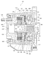
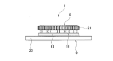
- FIG. 1 is a cross-sectional view of the clutch device according to the first embodiment.
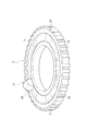
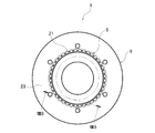
- FIG. 2 is a perspective view of the cam ring and the cam member of the cam mechanism according to the first embodiment.
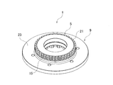
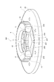
- FIG. 3 is an exploded perspective view of the cam mechanism according to the first embodiment.
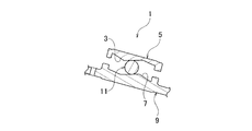
- FIG. 4 is an exploded perspective view when the cam member of the cam mechanism according to the first embodiment is arranged on the pressure ring.
- FIG. 5A is a perspective view when the cam ring and the pressure ring of the cam mechanism according to the first embodiment are not relatively rotated.
- FIG. 5B is a side view of the cam ring and pressure ring corresponding to FIG. 5A.
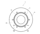
- FIG. 6A is a plan view of the cam ring and pressure ring corresponding to FIG. 5A.
- FIG. 6B is a cross-sectional view taken along line VIB-VIB of FIG. 6A.
- FIG. 7A is a perspective view when the cam ring and the pressure ring of the cam mechanism according to the first embodiment rotate relative to each other.
- FIG. 7B is a side view of the cam ring and pressure ring corresponding to FIG. 7A.
- FIG. 8A is a plan view of the cam ring and pressure ring corresponding to FIG. 7A.
- 8B is a cross-sectional view taken from line VIIIB-VIIIB in FIG. 8A. It is a perspective view of the cam mechanism which concerns on 2nd Embodiment. It is sectional drawing of the cam mechanism which concerns on 2nd Embodiment.
- the axis means the rotating shaft of the rotating member, and the radial direction means the direction orthogonal to this.
- Such a rotation axis usually coincides with the central axis of the cam mechanism.
- a cam mechanism is used in combination with, for example, a clutch device, an example of which is a multi-plate clutch.
- a clutch device an example of which is a multi-plate clutch.
- the combination with the multi-plate clutch is advantageous in that the torque to be transmitted can be controlled continuously in a quantitative manner, but is not necessarily limited to this.
- an appropriate friction clutch or other spline, dog, synchro cone, etc. Can be combined with a type clutch.
- the clutch device 101 includes an outer rotating member 103 and an inner rotating member 105 as a pair of rotating members that can rotate independently around an axis, and the outer rotating member 103 and the inner rotating member 105.
- An intermittent portion 107 that is arranged between the outer rotating member 103 and the inner rotating member 105 by axial movement, an actuator 109 that operates the intermittent portion 107, and an intermittent portion that is operated by the actuator 109.
- the cam mechanism 1 which operates 107 is provided.
- the pair of rotating members are not necessarily arranged on the inner side and the outer side, respectively.
- an independent intermittent part intervenes between these, and a rotating member may also serve as a clutch plate, respectively.
- the actuator 109 is connected to the cam ring 5 in a driving manner and rotates relative to the pressure ring 9 to cause a cam action, thereby connecting the clutch.
- the outer rotating member 103 is rotatably supported by a carrier 113 as a stationary member via a bearing 111, and includes a rotor 115 and a housing 117.
- the rotor 115 is made of a magnetic material, and is arranged such that one side extending portions 119 and 121 and a wall portion 123 that extend to the electromagnet 167 side of the actuator 109 in the axial direction cover the periphery of the electromagnet 167. 123 is arranged between the electromagnet 167 and the pilot clutch 163 of the actuator 109 in the axial direction.
- a member 125 made of a nonmagnetic material is integrally provided on the wall portion 123 by a fixing means such as welding. That is, since the nonmagnetic member 125 cuts the wall portion 123, the magnetic flux is guided to the armature 165 described later so as to bypass the member 125.
- the core 175 surrounding the electromagnet 167, the extended portions 119 and 121, the wall portion 123, and the armature 165 constitute a magnetic path that guides a closed magnetic flux loop. When the electromagnet 167 is excited, the magnetic flux attracts the armature 165 toward the wall portion 123.
- the rotor 115 is provided with an air gap that is opposed to the core 175 of the electromagnet 167 with a small gap therebetween, so that magnetic flux can be transferred from the core 175 of the electromagnet 167 to the rotor 115. .
- the pilot clutch 163 side of the rotor 115 is an other-side extension portion 127 extending in the axial direction, and a spline-shaped connection portion 129 is provided on the inner periphery of the other-side extension portion 127. It has been.
- the housing 117 is coupled to the coupling portion 129 so as to be integrally rotatable, and the axial position of the rotor 115 is positioned by abutment of the convex portion 131 provided on the housing 117 with the end portion, and fixing such as welding is performed. By means, it is fixed so as to be rotatable together with the housing 117.
- the housing 117 is made of a nonmagnetic material and has a bottomed cylindrical shape.
- a seal member 133 is provided between the housing 117 and the rotor 115 in the radial direction to partition the inside of the outer rotating member 103 from the outside.
- the bottom wall 135 of the housing 117 is provided with an injection hole 137 for allowing the lubricating oil to flow into the outer rotating member 103. After the lubricating oil is injected, the housing 117 is closed by the lid member 139.
- a spline-shaped engaging portion 141 is formed on the cylindrical inner periphery of the housing 117, and the outer clutch plate of the intermittent portion 107 is engaged.
- an engaging portion 143 having a concavo-convex shape in the circumferential direction is formed extending toward the rotor 115 in the axial direction.
- An outer plate is engaged with the recess.
- the engaging portion 143 is located on the inner peripheral side of the other extending portion 127 of the rotor 115, and the magnetic flux is transmitted to the other extending portion 127 by disposing the engaging portion 143 made of a nonmagnetic material. It has a difficult structure.
- a connecting member 145 such as a stud bolt is fixed to the bottom wall portion 135 of the housing 117, and one rotating member (not shown) of the input / output members is provided via the connecting member 145, for example.
- the outer rotating member 103 is connected to be rotatable together.
- a seal member 147 that partitions the inside and outside of the carrier 113 is disposed between the outer rotating member 103 and the carrier 113, and a dust cover 149 is disposed so as to cover the periphery of the seal member 147. Yes.
- the inner rotating member 105 is disposed on the rotational axis of the outer rotating member 103 so as to be rotatable relative to the outer rotating member 103.
- the inner rotating member 105 is formed in a hollow shape, and is rotatably supported by the outer rotating member 103 via an X ring 151, a sliding bush 153, and a bearing 155 on the outer periphery.
- the X ring 151 is a sealing means for partitioning the outside with respect to the outside after the lubricating oil is sealed inside the outer rotating member 103.
- a spline-shaped engaging portion 157 is formed on the outer periphery of the inner rotating member 105, and the inner clutch plate of the intermittent portion 107 and the pressure ring 9 of the cam mechanism 1 are engaged.
- a partition wall 159 is provided as a single member continuous with the inner rotation member 105 at the central portion on the axial center side of the inner rotation member 105, and partitions the inside and the outside of the outer rotation member 103.
- a spline-shaped connecting portion 161 is formed on the inner periphery of the inner rotating member 105.
- the other rotating member (not shown) of the input / output members is connected to the inner rotating member 105 so as to be integrally rotatable.
- the driving torque transmitted between the inner rotating member 105 and the outer rotating member 103 is interrupted by the interrupting portion 107.
- the intermittent portion 107 is disposed in the outer rotating member 103 and includes a plurality of outer clutch plates and a plurality of inner clutch plates.
- the plurality of outer clutch plates are engaged with an engaging portion 141 formed on the inner periphery of the housing 117 so as to be axially movable and integrally rotatable with the outer rotating member 103.
- the plurality of inner clutch plates are alternately arranged in the axial direction with respect to the plurality of outer clutch plates, and can be moved in the axial direction to an engaging portion 157 formed on the outer periphery of the inner rotating member 105 and rotate integrally with the inner rotating member 105. Engaged as possible.
- the intermittent portion 107 is a multi-plate clutch composed of a plurality of outer clutch plates and a plurality of inner clutch plates, and is a control type friction clutch capable of intermediate control of transmission torque with sliding friction.
- Such an interrupting portion 107 is interrupted by the operation of the actuator 109, and interrupts the driving torque transmitted between the outer rotating member 103 and the inner rotating member 105.
- the actuator 109 includes a pilot clutch 163, an armature 165, an electromagnet 167, and the like.
- the pilot clutch 163 is arranged between the rotor 115 and the armature 165 in the axial direction in the outer rotating member 103.
- the pilot clutch 163 includes a plurality of outer plates that are axially movable to the engaging portion 143 of the housing 117 and are connected to the outer rotating member 103 so as to be integrally rotatable, and a plurality of outer plates on the outer periphery of the cam ring 5 of the cam mechanism 1.
- it is composed of a plurality of inner plates which are alternately arranged in the axial direction and are movable in the axial direction and connected to the cam ring 5 so as to be integrally rotatable.
- Such a pilot clutch 163 is connected by the armature 165 being attracted and moved by the excitation of the electromagnet 167.
- the armature 165 is made of a magnetic material, is formed in an annular shape, is disposed to face the rotor 115 with the pilot clutch 163 interposed therebetween in the axial direction, and is disposed in the outer rotating member 103 so as to be movable in the axial direction.
- the armature 165 is attracted and moved to the rotor 115 side by a magnetic flux loop formed when the electromagnet 167 is excited, and the pilot clutch 163 is connected.
- the electromagnet 167 is disposed outside the outer rotating member 103 via the bearing 169 in the rotor 115 and is prevented from rotating by the carrier 113 by the rotation preventing member 171 and includes an electromagnetic coil 173 and a core 175.
- the electromagnetic coil 173 is annularly molded with a predetermined number of turns and molded with resin.
- a lead wire 177 is connected to the electromagnetic coil 173, and is connected to a controller (not shown) that controls energization via the lead wire 177.
- a core 175 is disposed around the electromagnetic coil 173.
- the core 175 is made of a magnetic material so that a magnetic field is formed by energization of the electromagnetic coil 173, has a predetermined magnetic path cross-sectional area, and is disposed between the electromagnetic coil 173 and the rotor 115 in the radial direction.
- the magnetic flux is transmitted along with 115 to form a magnetic flux loop.
- the electromagnet 167 is energized to the electromagnetic coil 173 so as to generate the necessary friction torque at the intermittent portion 107 under the control of the controller, the pilot clutch 163 is connected, and the thrust force is generated by the cam mechanism 1.
- the cam mechanism 1 is composed of a cam ring 5, a pressure ring 9, and a cam member 11.
- the cam mechanism 1 is adjacent to the clutch device 101, and in particular, the pressure ring 9 is adjacent to the intermittence portion 107. Therefore, the pressure ring 9 can exert a pressing force on the intermittence portion 107 to connect the clutch.
- the cam ring 5 is disposed on the outer periphery of the inner rotating member 105 so as to be movable in the axial direction, and a plurality of inner plates of the pilot clutch 163 can be rotated integrally with an uneven engagement portion 21 formed on the outer diameter portion of the cam ring 5. It is connected. That is, the cam ring 5 forms a ring around the axis.
- a thrust bearing 179 that receives a thrust reaction force generated in the cam mechanism 1 is disposed.
- the pressure ring 9 is axially movable to the engaging portion 157 of the inner rotating member 105 and is disposed so as to be rotatable integrally with the inner rotating member 105.
- the pressure ring 9 is axially connected to the intermittent portion 107 so as to be able to contact the clutch plate of the intermittent portion 107. Adjacent to each other.
- the pressure ring 9 is axially moved in the connecting direction of the intermittent portion 107 by the thrust force generated by the cam mechanism 1, and the annular pressing portion 23 formed on the outer peripheral side applies a pressing force to the plurality of clutch plates of the intermittent portion 107. Grant and connect.
- a plurality of cam surfaces 3 and 7 are formed in the circumferential direction on the axially opposed surfaces of the pressure ring 9 and the cam ring 5, respectively.
- a cam member 11 is interposed between the seven members.
- This cam member 11 causes the pressure ring 9 to be connected to the intermittent portion 107 side with a strength corresponding to the friction torque generated in the pilot clutch 163 when a differential rotation occurs between the cam ring 5 and the pressure ring 9 due to the connection of the pilot clutch 163. Generates a cam thrust force that moves in the axial direction.
- the electromagnet 167 when the electromagnet 167 is energized, the magnetic lines of force are circulated through the core 175, the one-side extending portions 119 and 121 of the rotor 115, the wall portion 123, and the armature 165, thereby forming a magnetic flux loop.
- the armature 165 is attracted and moved to the electromagnet 167 side, and the pilot clutch 163 is fastened.
- the fastening torque of the pilot clutch 163 is converted into axial thrust through the cam mechanism 1, and the pressing portion 23 of the pressure ring 9 presses the plurality of clutch plates of the intermittent portion 107 to connect the intermittent portion 107.
- connection of the intermittent portion 107 connects the outer rotating member 103 and the inner rotating member 105, and for example, it is possible to transmit driving torque between the input / output members.
- the cam mechanism 1 includes a cam ring 5 having a plurality of cam surfaces 3 formed in the circumferential direction, and is rotatable relative to the cam ring 5 in the axial direction. And a pressure ring 9 formed with a plurality of cam surfaces 7 facing the cam surface 3 of the cam ring 5 in the circumferential direction, and between the cam surfaces 3 and 7 of the cam ring 5 and the pressure ring 9, the cam ring 5 and the pressure A plurality of cam members 11 that move relative to the circumferential direction between the cam surfaces 3 and 7 by the relative rotation with the ring 9 and move the pressure ring 9 in the axial direction are provided.
- the cam member 11 is a tapered roller that tapers inward in the radial direction.
- the cam surfaces 3 and 7 of the cam ring 5 and the pressure ring 9 are in relative movement with respect to the cam surfaces 3 and 7 of the cam member 11.
- the inclination is set so that the center position on the inner diameter side of the cam member 11 and the center position on the outer diameter side of the cam member 11 are the same in the radial direction.
- cam ring 5 and the pressure ring 9 include an inner diameter wall portion 13 that restricts the movement of the cam member 11 toward the inner diameter side, and an outer diameter wall portion 15 that restricts the movement of the cam member 11 toward the outer diameter side. Is provided.
- the inner diameter wall portion 13 and the outer diameter wall portion 15 have a circular shape capable of simultaneously regulating the plurality of cam members 11.
- the inner end peripheral wall 17 and the outer end peripheral wall 19 of the taper roller in the cam member 11 are formed in curved shapes 20 and 22.
- the cam member 11 is formed of a material having higher strength than the cam surfaces 3 and 7.
- Each cam member 11 is a tapered roller formed in a truncated cone shape and tapering inward in the radial direction. That is, each cam member 11 has a conical surface that tapers inward in the radial direction. This alleviates the peripheral speed difference with respect to the cam surfaces 3 and 7 and reduces friction.
- Each taper roller is dimensioned so that the conical surface bus converges in the axis, preferably to minimize the peripheral speed difference, i.e. the friction.
- a plurality of cam members 11 are arranged at equal intervals in the circumferential direction of the cam ring 5 and the pressure ring 9 between the cam surfaces 3 and 7 formed on the opposing surfaces of the cam ring 5 and the pressure ring 9 facing each other in the axial direction. ing.
- the cam ring 5 and the pressure ring 9 rotate relative to each other due to a rotation difference between the cam ring 5 and the pressure ring 9 by controlling the rotation of the cam ring 5 by fastening the pilot clutch 163.
- the cam member 11 which is a taper roller rolls on the cam surfaces 3 and 7 by the relative rotation of the cam ring 5 and the pressure ring 9, and also moves the pressure ring 9 in the axial direction as described later.
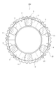
- the cam ring 5 generally has an annular shape, and the plurality of cam surfaces 3 are arranged in the circumferential direction on one surface of the annular ring facing in the axial direction.
- the cam surface 3 of the cam ring 5 is formed of two inclined surfaces that are inclined upward on both sides in the circumferential direction, which is both sides of the moving direction of the cam member 11, with respect to one cam member 11.
- a plurality of crests and troughs are continuously formed at equal intervals in the circumferential direction with respect to each cam member 11 as a set. That is, each cam surface 3 is inclined in the circumferential direction with respect to the circumferential surface orthogonal to the axis.
- each cam surface 3 of the cam ring 5 is inclined so that the two inclined surfaces expand from the inner diameter side toward the outer diameter side, and therefore, while the cam members 11 roll, Maintain contact. That is, each cam surface 3 is inclined not only in the circumferential direction but also in a direction in which the surface is directed outward in the radial direction, and is in line contact with the conical surface of each cam member 11. This also helps to hold each cam member 11 radially.
- each cam surface 3 is an inclined surface dimensioned to direct the cam member 11 such that the generatrix of the conical surface always intersects the axis, an example of which is a helical surface centered on the axis . In such a combination, each cam member 11 does not cause skew (inclination) with respect to the radial direction and does not cause a difference in peripheral speed, so that it can roll on each cam surface 3 without friction.
- the cam surface 7 of the pressure ring 9 is disposed opposite to the cam surface 3 of the cam ring 5 in the axial direction.
- the pressure ring 9 is also generally ring-shaped and includes a plurality of cam surfaces 7 corresponding to the plurality of cam surfaces 3.
- the cam surface 7 of the pressure ring 9 has the same inclination angle and the same shape as the cam surface 3 of the cam ring 5, and is at an initial position where no rotational difference is generated between the cam ring 5 and the pressure ring 9.
- the cam ring 5 is arranged symmetrically facing the cam surface 3 in the axial direction.
- the movement distance on the outer diameter side of the cam member 11 can be determined in the circumferential movement of the cam surfaces 3 and 7 of the cam member 11.
- the moving distance on the inner diameter side of the member 11 can be made larger, and blurring of the rotational axis in the circumferential direction of the cam ring 5 and the pressure ring 9 of the cam member 11 can be prevented.
- cam members 11 each composed of a plurality of tapered rollers are arranged in the valleys between the cam surfaces 3 and 7, respectively.
- the cam ring 5 and the pressure ring 9 are closest to each other in the axial direction.
- the pressing portion 23 of the pressure ring 9 presses the plurality of clutch plates of the intermittent portion 107, and the intermittent portion 107 is connected.
- the cam member 11 is formed of a taper roller, and the cam surfaces 3 and 7 are inclined so as to expand from the inner diameter side toward the outer diameter side. Even if the cam member 11 moves to any position on the cam surfaces 3 and 7, the center position on the inner diameter side of the cam member 11 and the center position on the outer diameter side of the cam member 11 can be made the same in the radial direction. .
- the design accuracy of the cam mechanism 1 can be improved, the setting of the fastening torque of the pilot clutch 163 in the actuator 109 of the clutch device 101 can be easily changed, and the intermittent portion 107 of the clutch device 101 can be changed.
- the intermittent characteristics in can be improved.
- the cam ring 5 and the pressure ring 9 include an inner diameter wall portion 13 positioned on the inner diameter side of each of the cam surfaces 3 and 7, and an outer diameter wall portion 15 positioned on the outer diameter side of the cam surfaces 3 and 7. Is provided.
- the inner diameter wall portion 13 and the outer diameter wall portion 15 regulate the movement of the cam member 11 toward the inner diameter side in the circumferential movement of the cam surfaces 3 and 7 of the cam member 11, and the outer diameter The wall portion 15 restricts the movement of the cam member 11 toward the outer diameter side.
- the inner diameter wall portion 13 and the outer diameter wall portion 15 are formed on the opposing surfaces of the cam ring 5 and the pressure ring 9 so as to face each other in the same shape, and have an inner diameter with respect to the plurality of cam members 11. The movement to the side and the movement to the outer diameter side can be restricted.
- the cam member 11 can be stably moved in the circumferential direction of the cam surfaces 3 and 7, and the axial movement of the pressure ring 9 can be stabilized.
- the inner diameter wall portion 13 and the outer diameter wall portion 15 have a circular shape that is continuously formed in an annular shape in the circumferential direction so that the plurality of cam members 11 can be simultaneously regulated.
- the inner diameter wall portion 13 and the outer diameter wall portion 15 have a circular shape, the circumferential movement of all the cam surfaces 3 and 7 of the plurality of cam members 11 can be stably performed.
- the axial movement of the pressure ring 9 can be stabilized.
- the inner diameter wall portion 13 and the outer diameter wall portion 15 are provided so that the inner wall surface in contact with the cam member 11 is perpendicular to the end surfaces of the cam ring 5 and the pressure ring 9.
- the inner end peripheral wall 17 and the outer end peripheral wall 19 of the cam member 11 sliding with the inner wall surfaces of the inner diameter wall portion 13 and the outer diameter wall portion 15 are formed in curved surfaces 20 and 22.
- the cam member 11 can smoothly move along the curved surfaces of the inner end peripheral wall 17 and the outer end peripheral wall 19.
- the cam surfaces 3 and 7 can be moved.
- the cam member 11 is formed of a material having higher material strength than the cam surfaces 3 and 7, that is, the cam ring 5 and the pressure ring 9.
- the cam member 11 is composed of a taper roller, the contact between the cam member 11 and the cam surfaces 3 and 7 is a line contact, and the contact pressure is higher than the point contact when a ball is used for the cam member 11. Has been lowered.
- cam member 11 When a ball is used for the cam member 11, if the material strength of the cam member 11 is higher than the material strength of the cam surfaces 3 and 7, stress concentrates on the contact portion of the cam surfaces 3 and 7 with the cam member 11, The cam surfaces 3 and 7 may be damaged.
- the cam member 11 may be deformed by the contact pressure with the cam surfaces 3 and 7.
- the cam member 11 made of a taper roller has a reduced contact pressure with the cam surfaces 3 and 7, so even if the material strength of the cam member 11 is higher than that of the cam surfaces 3 and 7, the cam surface 3 , 7 and deformation of the cam member 11 can be prevented.
- the clutch device 101 it is possible to increase the fastening force of the pilot clutch 163 and increase the moving stroke in the axial direction of the pressure ring 9 without increasing costs due to design changes or design changes.
- the intermittent characteristics of the part 107 can be improved.
- the cam member 11 is composed of a tapered roller whose rotation diameter increases from the inner diameter side toward the outer diameter side, and the cam surfaces 3 and 7 of the cam ring 5 and the pressure ring 9 are cams of the cam member 11.
- the center position on the inner diameter side of the cam member 11 and the center position on the outer diameter side of the cam member 11 in the relative movement with respect to the surfaces 3 and 7 are set so as to be the same in the radial direction.
- the axial movement of the pressure ring 9 can be designed without considering the frictional resistance caused by the sliding of the cam member 11 on the cam surfaces 3 and 7. Accuracy can be improved.
- the cam ring 5 and the pressure ring 9 include an inner diameter wall portion 13 that restricts the movement of the cam member 11 toward the inner diameter side, and an outer diameter wall portion 15 that restricts the movement of the cam member 11 toward the outer diameter side. Since it is provided, the cam member 11 can be stably moved in the circumferential direction of the cam surfaces 3 and 7, and the axial movement of the pressure ring 9 can be stabilized.
- the inner diameter wall portion 13 and the outer diameter wall portion 15 have a circular shape capable of simultaneously regulating the plurality of cam members 11, the circumferential direction of all the cam surfaces 3, 7 of the plurality of cam members 11 is provided. The movement can be stably performed, and the axial movement of the pressure ring 9 can be stabilized.
- the cam member 11 follows the curved surface of the inner end peripheral wall 17 and the outer end peripheral wall 19.
- the cam surfaces 3 and 7 can be moved smoothly.
- the cam member 11 is formed of a material having a material strength higher than that of the cam surfaces 3 and 7, the cam member 11 can be prevented from being deformed and a high cam thrust force of the cam mechanism 1 can be obtained.
- the design accuracy of the cam mechanism 1 can be improved, so that an accurate design according to the characteristics of the interrupting portion 107 can be performed. Intermittent characteristics can be improved.
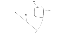
- the outer end surface 203 of the tapered roller in the cam member 11 includes a convex portion that is convex outward in the radial direction, and the convex portion is an appropriate curved surface, for example, a spherical surface.
- the curvature radius R1 of the curved surface is set smaller than the radius R2 of the inner peripheral surface 205 of the outer diameter wall portion 15.
- the outer diameter wall portion 15 may be provided on only one of the cam ring 5 and the pressure ring 9.
- cam surfaces 3 and 7 of the cam ring 5 and the pressure ring 9 are a first cam surface 207 where the cam member 11 is relatively moved from the initial position to the first operation position, and the cam member is operated second from the first operation position.
- the first cam surface 207 is set to have a larger inclination angle than the second cam surface 209.
- the outer diameter wall portion 15 is formed in a circular shape, that is, in a cylindrical shape, so that the inner peripheral surface of the outer diameter wall portion 15 is formed.
- 205 (see FIG. 13) will have at least two contact points.
- outer diameter wall portion 15 is provided on each of the cam ring 5 and the pressure ring 9, the outer end surface 203 and the inner peripheral surface 205 of the outer diameter wall portion 15 come into contact at least at four points. .
- the outer end surface 203 of the tapered roller in the cam member 11 includes a convex portion that is convex outward in the radial direction, and the convex portion is an appropriate curved surface, for example, a spherical surface.
- the radius of curvature R1 of the outer end surface 203 of the tapered roller is set to be smaller than the radius R2 of the inner peripheral surface 205 of the outer diameter wall portion 15.
- the outer end surface 203 of the taper roller is convex outward in the radial direction and has a radius of curvature R1 smaller than the radius R2 of the inner peripheral surface 205, it slides in point contact with the inner peripheral surface 205 of the outer peripheral wall portion 15. To do.
- the radius of curvature R1 of the outer end surface 203 of the taper roller is the same as the definition based on normal technical common sense, and is defined as the radius of the curved surface of the outer end surface 203 as understood with reference to FIG.
- the curvature radius R1 of the outer end surface 203 is made smaller than the radius R2 of the inner peripheral surface 205 of the outer diameter wall portion 15 in this way, so that the cam member 11 is connected to the cam ring 5.
- the pressure ring 9 relative to each other between the cam surfaces 3 and 7, the contact point between the outer end surface 203 and the inner peripheral surface 205 of the outer diameter wall portion 15 is one point, and the outer diameter wall portion 15 is connected to the cam ring 5.
- the pressure ring 9 is provided on each of the pressure rings 9, two contact points between the outer end surface 203 and the inner peripheral surface 205 of the outer diameter wall portion 15 can be provided.
- the outer diameter wall portion 15 is provided only on the cam ring 5 or only on the pressure ring 9 as shown in FIGS.
- the inner diameter wall 13 is also provided only on the cam ring 5 or only on the pressure ring 9.
- the contact point between the outer end surface 203 of the cam member 11 and the inner peripheral surface 205 of the outer diameter wall portion 15 is set to 1. It can be a point, and the frictional resistance can be further reduced.
- cam surfaces 3 and 5 of the cam ring 5 and the pressure ring 9 include a first cam surface 207 and a second cam surface 209.
- the first cam surface 207 moves relative to a certain extent between the cam surfaces 3 and 7 of the cam ring 5 and the pressure ring 9 from the initial position from the valleys of the cam surfaces 3 and 7 positioned at the initial position of the cam member 11. It is provided in the range up to the first operating position when That is, the first cam surface 207 is continuously inclined from the trough, and the trough calms the cam member 11 to the initial position, but when the cam member 11 rolls on the first cam surface 207, the first cam surface 207 Move axially to the operating position.
- the axial stroke of the pressure ring 9 with respect to the rotational phase between the cam ring 5 and the pressure ring 9 can be increased.
- the second cam surface 209 is formed at the peak portion of the cam surfaces 3 and 7 where the cam member 11 completes the relative movement between the cam surfaces 5 and 7 between the cam ring 5 and the pressure ring 9 from the first operation position. It is provided in the range up to the second operating position which is the top. That is, the first cam surface 207 to the second cam surface 209 are continuously inclined, and when the cam member 11 rolls on the second cam surface 209, it moves in the axial direction to the second operating position.
- the rotational phase of the cam ring 5 and the pressure ring 9 is made larger than that of the first cam surface 207, and the displacement ratio of the axial stroke of the pressure ring 9 to this is made smaller.
- the thrust force of the pressure ring 9 is increased.
- the first cam surface 207 and the second cam surface 209 are set such that the inclination angle of the first cam surface 207 is larger than the inclination angle of the second cam surface 209.
- the cam member 11 moves on the second cam surface 209, that is, when the cam member 11 moves from the first operation position to the second operation position, the cam member 11 is positioned on the first cam surface 207.
- the fastening force of the intermittent portion 107 can be accurately controlled, and the intermittent characteristic of the intermittent portion 107 is improved. Can do.
- the outer end surface 203 of the taper roller in the cam member 11 is formed in a spherical shape, and the radius of curvature R1 of the outer end surface 203 of the taper roller is larger than the radius R2 of the inner peripheral surface 205 of the outer diameter wall portion 15. Since it is set to be small, the contact between the outer end surface 203 of the cam member 11 and the inner peripheral surface 205 of the outer diameter wall portion 15 in the relative movement between the cam surfaces 3 and 7 of the cam ring 5 and the pressure ring 9 of the cam member 11. The points can be reduced, and the frictional resistance can be reduced.
- outer diameter wall portion 15 is provided only on one of the cam ring 5 and the pressure ring 9, the contact between the outer end surface 203 of the cam member 11 and the inner peripheral surface 205 of the outer diameter wall portion 15. A point can be made into one point, and also frictional resistance can be reduced.
- first cam surface 207 is set to have an inclination angle larger than that of the second cam surface 209, the first cam surface 207 can improve the responsiveness from the initial position of the cam member 11, and second The cam surface 209 can accurately control the axial movement of the pressure ring 9.
- the cam ring and the pressure ring are provided with the inner diameter wall portion and the outer diameter wall portion.
- the present invention is not limited thereto, and at least one of the cam ring and the pressure ring includes an inner diameter wall portion and What is necessary is just to provide an outer-diameter wall part.
- the inner end peripheral wall and the outer end peripheral wall are formed in a curved shape.
- the present invention is not limited thereto, and one of the inner end peripheral wall and the outer end peripheral wall is formed in a curved shape. May be.
- the contact point between the outer end surface 203 of the cam member 11 and the inner peripheral surface 205 of the outer diameter wall portion 15 is set to 1.
- the outer end surface 203 of the cam member 11 is not formed into a spherical shape with a radius of curvature R1 as described above, a convex portion (protrusion or the like) is formed in the vicinity of the axial center of the outer end surface 203 of the cam member 11. May be provided so as to abut and slide on the outer diameter wall portion. Also in this case, a curved surface or a flat surface may be formed so that the front end of the convex portion or the edge portion of the front end does not come into contact with the outer diameter wall portion.
- the actuator is an electromagnetic actuator.
- the present invention is not limited to this, for example, an actuator that causes relative rotation between the cam ring and the pressure ring, such as a motor, gear, and cam mechanism. Any actuator may be used.
Landscapes
- Engineering & Computer Science (AREA)
- General Engineering & Computer Science (AREA)
- Mechanical Engineering (AREA)
- Physics & Mathematics (AREA)
- Electromagnetism (AREA)
- Mechanical Operated Clutches (AREA)
Abstract
L'invention concerne un mécanisme à came (1) utilisé en combinaison avec un embrayage (107) permettant de transmettre un couple entre un premier élément rotatif et un second élément rotatif, le mécanisme à came comprenant : une anneau de came (5) formant un espace annulaire autour d'un arbre et dans lequel une face de l'espace annulaire orientée dans la direction axiale est munie de multiples faces de came (3) côte à côte dans la direction circonférentielle et inclinées chacune dans la direction circonférentielle par rapport à un plan circonférentiel perpendiculaire à l'arbre ; un anneau de pression (9) adjacent à ladite face de l'anneau de came (5) dans la direction axiale, muni de multiples faces de came (7) orientées vers ladite face de l'anneau de came (5) et symétriques aux multiples faces de came (3) de l'anneau de came (5), l'anneau de pression pouvant tourner par rapport à l'anneau de came (5) autour de l'arbre ; et de multiples rouleaux coniques (11) interposés entre l'anneau de came (5) et l'anneau de pression (9), présentant des faces coniques respectives s'effilant vers l'intérieur dans la direction radiale, et pouvant rouler sur les faces de came (3, 7).
Priority Applications (3)
| Application Number | Priority Date | Filing Date | Title |
|---|---|---|---|
| EP16892665.7A EP3425239A4 (fr) | 2016-03-04 | 2016-10-14 | Mécanisme à came et dispositif d'embrayage utilisant ledit mécanisme à came |
| CN201680062027.0A CN108138922B (zh) | 2016-03-04 | 2016-10-14 | 凸轮机构及使用了该凸轮机构的离合器装置 |
| US15/950,237 US10704612B2 (en) | 2016-03-04 | 2018-04-11 | Cam mechanism and clutch device with the same |
Applications Claiming Priority (4)
| Application Number | Priority Date | Filing Date | Title |
|---|---|---|---|
| JP2016-041787 | 2016-03-04 | ||
| JP2016041787 | 2016-03-04 | ||
| JP2016-158619 | 2016-08-12 | ||
| JP2016158619A JP6735180B2 (ja) | 2016-03-04 | 2016-08-12 | カム機構及びこのカム機構を用いたクラッチ装置。 |
Related Child Applications (1)
| Application Number | Title | Priority Date | Filing Date |
|---|---|---|---|
| US15/950,237 Continuation US10704612B2 (en) | 2016-03-04 | 2018-04-11 | Cam mechanism and clutch device with the same |
Publications (1)
| Publication Number | Publication Date |
|---|---|
| WO2017149829A1 true WO2017149829A1 (fr) | 2017-09-08 |
Family
ID=59742684
Family Applications (1)
| Application Number | Title | Priority Date | Filing Date |
|---|---|---|---|
| PCT/JP2016/080462 Ceased WO2017149829A1 (fr) | 2016-03-04 | 2016-10-14 | Mécanisme à came et dispositif d'embrayage utilisant ledit mécanisme à came |
Country Status (1)
| Country | Link |
|---|---|
| WO (1) | WO2017149829A1 (fr) |
Cited By (6)
| Publication number | Priority date | Publication date | Assignee | Title |
|---|---|---|---|---|
| WO2019171459A1 (fr) * | 2018-03-06 | 2019-09-12 | Gkn ドライブライン ジャパン株式会社 | Mécanisme de came à faible hystérésis pourvu de rouleaux coniques |
| WO2019244268A1 (fr) * | 2018-06-20 | 2019-12-26 | Gkn ドライブライン ジャパン株式会社 | Mécanisme de came à faible hystérésis équipé d'un rouleau conique |
| WO2020008507A1 (fr) * | 2018-07-02 | 2020-01-09 | Gkn ドライブライン ジャパン株式会社 | Dispositif d'embrayage à friction |
| CN110821981A (zh) * | 2019-11-28 | 2020-02-21 | 河北艾斯特车桥有限公司 | 一种用于重型车辆的全盘式制动器 |
| CN112334675A (zh) * | 2018-07-06 | 2021-02-05 | 株式会社电装 | 离合装置 |
| US11773919B2 (en) | 2019-03-26 | 2023-10-03 | Gkn Automotive Limited | Disconnectable coupling with lubrication control |
Citations (4)
| Publication number | Priority date | Publication date | Assignee | Title |
|---|---|---|---|---|
| JPH0260525B2 (fr) * | 1982-12-30 | 1990-12-17 | Aisin Aw Co | |
| JPH0791514A (ja) * | 1990-12-14 | 1995-04-04 | Boris Borisovich Ropateikku | 回転運動から往復運動への、およびその逆の変換機構 |
| JP2001041230A (ja) * | 1999-07-29 | 2001-02-13 | Nsk Ltd | スラスト円錐ころ軸受 |
| JP2005201288A (ja) * | 2004-01-13 | 2005-07-28 | Kubota Tekkosho:Kk | カップリング |
-
2016
- 2016-10-14 WO PCT/JP2016/080462 patent/WO2017149829A1/fr not_active Ceased
Patent Citations (4)
| Publication number | Priority date | Publication date | Assignee | Title |
|---|---|---|---|---|
| JPH0260525B2 (fr) * | 1982-12-30 | 1990-12-17 | Aisin Aw Co | |
| JPH0791514A (ja) * | 1990-12-14 | 1995-04-04 | Boris Borisovich Ropateikku | 回転運動から往復運動への、およびその逆の変換機構 |
| JP2001041230A (ja) * | 1999-07-29 | 2001-02-13 | Nsk Ltd | スラスト円錐ころ軸受 |
| JP2005201288A (ja) * | 2004-01-13 | 2005-07-28 | Kubota Tekkosho:Kk | カップリング |
Non-Patent Citations (1)
| Title |
|---|
| See also references of EP3425239A4 * |
Cited By (14)
| Publication number | Priority date | Publication date | Assignee | Title |
|---|---|---|---|---|
| WO2019171459A1 (fr) * | 2018-03-06 | 2019-09-12 | Gkn ドライブライン ジャパン株式会社 | Mécanisme de came à faible hystérésis pourvu de rouleaux coniques |
| CN112334679B (zh) * | 2018-06-20 | 2023-09-15 | 吉凯恩汽车有限公司 | 具备圆锥滚柱的低滞后的凸轮机构 |
| WO2019244268A1 (fr) * | 2018-06-20 | 2019-12-26 | Gkn ドライブライン ジャパン株式会社 | Mécanisme de came à faible hystérésis équipé d'un rouleau conique |
| CN112334679A (zh) * | 2018-06-20 | 2021-02-05 | 吉凯恩汽车有限公司 | 具备圆锥滚柱的低滞后的凸轮机构 |
| JPWO2019244268A1 (ja) * | 2018-06-20 | 2021-05-13 | ジーケーエヌ オートモーティブ リミテッド | テーパローラを備えた低ヒステリシスのカム機構 |
| WO2020008507A1 (fr) * | 2018-07-02 | 2020-01-09 | Gkn ドライブライン ジャパン株式会社 | Dispositif d'embrayage à friction |
| CN112352114A (zh) * | 2018-07-02 | 2021-02-09 | 吉凯恩汽车有限公司 | 摩擦离合器装置 |
| JPWO2020008507A1 (ja) * | 2018-07-02 | 2021-05-13 | ジーケーエヌ オートモーティブ リミテッド | 摩擦クラッチ装置 |
| CN112352114B (zh) * | 2018-07-02 | 2022-02-15 | 吉凯恩汽车有限公司 | 摩擦离合器装置 |
| JP7065189B2 (ja) | 2018-07-02 | 2022-05-11 | ジーケーエヌ オートモーティブ リミテッド | 摩擦クラッチ装置 |
| CN112334675A (zh) * | 2018-07-06 | 2021-02-05 | 株式会社电装 | 离合装置 |
| US11773919B2 (en) | 2019-03-26 | 2023-10-03 | Gkn Automotive Limited | Disconnectable coupling with lubrication control |
| CN110821981A (zh) * | 2019-11-28 | 2020-02-21 | 河北艾斯特车桥有限公司 | 一种用于重型车辆的全盘式制动器 |
| CN110821981B (zh) * | 2019-11-28 | 2021-10-01 | 河北埃克斯福动力科技有限公司 | 一种用于重型车辆的全盘式制动器 |
Similar Documents
| Publication | Publication Date | Title |
|---|---|---|
| WO2017149829A1 (fr) | Mécanisme à came et dispositif d'embrayage utilisant ledit mécanisme à came | |
| US10704612B2 (en) | Cam mechanism and clutch device with the same | |
| JP7070506B2 (ja) | 転動体カム、および、それを用いたクラッチ装置 | |
| CN105723112B (zh) | 减少了摩擦损失的离合装置以及差速装置 | |
| US10138954B2 (en) | Rotation transmission device | |
| KR20160003856A (ko) | 전자 액추에이터 | |
| CN106104051B (zh) | 旋转传递装置 | |
| JP2015102185A (ja) | 断続装置及びこの断続装置を用いたデファレンシャル装置 | |
| JP4715690B2 (ja) | 駆動力伝達装置 | |
| JP6247519B2 (ja) | 断続装置 | |
| JP2008082397A (ja) | 駆動力伝達装置 | |
| US20150260232A1 (en) | Universal joint | |
| KR20100063304A (ko) | 액티브 토크전달장치 | |
| US8276724B2 (en) | Power transmission system for vehicle changing power transmission state by electric control | |
| WO2020009199A1 (fr) | Élément de roulement à came et dispositif d'embrayage utilisant celui-ci | |
| WO2019171459A1 (fr) | Mécanisme de came à faible hystérésis pourvu de rouleaux coniques | |
| JP2018141512A (ja) | 動力伝達装置 | |
| JP4686952B2 (ja) | 駆動力伝達装置 | |
| JP4952238B2 (ja) | 駆動力伝達装置 | |
| JP4239680B2 (ja) | 電磁クラッチ機構 | |
| EP2290253B1 (fr) | Système de transmission de puissance pour véhicule changeant d'état de transmission de puissance par commande électrique | |
| JP2004239311A (ja) | 摩擦クラッチ | |
| JP5141804B2 (ja) | 駆動力伝達装置 | |
| JP2019095028A (ja) | 動力伝達装置 | |
| JP2013238255A (ja) | カム機構、駆動力伝達装置、およびモータカム装置 |
Legal Events
| Date | Code | Title | Description |
|---|---|---|---|
| NENP | Non-entry into the national phase |
Ref country code: DE |
|
| 121 | Ep: the epo has been informed by wipo that ep was designated in this application |
Ref document number: 16892665 Country of ref document: EP Kind code of ref document: A1 |