WO2020008507A1 - Dispositif d'embrayage à friction - Google Patents
Dispositif d'embrayage à friction Download PDFInfo
- Publication number
- WO2020008507A1 WO2020008507A1 PCT/JP2018/025079 JP2018025079W WO2020008507A1 WO 2020008507 A1 WO2020008507 A1 WO 2020008507A1 JP 2018025079 W JP2018025079 W JP 2018025079W WO 2020008507 A1 WO2020008507 A1 WO 2020008507A1
- Authority
- WO
- WIPO (PCT)
- Prior art keywords
- cam
- rotating body
- support
- clutch
- pressure plate
- Prior art date
- Legal status (The legal status is an assumption and is not a legal conclusion. Google has not performed a legal analysis and makes no representation as to the accuracy of the status listed.)
- Ceased
Links
Images




Classifications
-
- F—MECHANICAL ENGINEERING; LIGHTING; HEATING; WEAPONS; BLASTING
- F16—ENGINEERING ELEMENTS AND UNITS; GENERAL MEASURES FOR PRODUCING AND MAINTAINING EFFECTIVE FUNCTIONING OF MACHINES OR INSTALLATIONS; THERMAL INSULATION IN GENERAL
- F16D—COUPLINGS FOR TRANSMITTING ROTATION; CLUTCHES; BRAKES
- F16D13/00—Friction clutches
- F16D13/22—Friction clutches with axially-movable clutching members
- F16D13/38—Friction clutches with axially-movable clutching members with flat clutching surfaces, e.g. discs
- F16D13/52—Clutches with multiple lamellae ; Clutches in which three or more axially moveable members are fixed alternately to the shafts to be coupled and are pressed from one side towards an axially-located member
-
- F—MECHANICAL ENGINEERING; LIGHTING; HEATING; WEAPONS; BLASTING
- F16—ENGINEERING ELEMENTS AND UNITS; GENERAL MEASURES FOR PRODUCING AND MAINTAINING EFFECTIVE FUNCTIONING OF MACHINES OR INSTALLATIONS; THERMAL INSULATION IN GENERAL
- F16D—COUPLINGS FOR TRANSMITTING ROTATION; CLUTCHES; BRAKES
- F16D27/00—Magnetically- or electrically- actuated clutches; Control or electric circuits therefor
- F16D27/10—Magnetically- or electrically- actuated clutches; Control or electric circuits therefor with an electromagnet not rotating with a clutching member, i.e. without collecting rings
- F16D27/108—Magnetically- or electrically- actuated clutches; Control or electric circuits therefor with an electromagnet not rotating with a clutching member, i.e. without collecting rings with axially movable clutching members
-
- F—MECHANICAL ENGINEERING; LIGHTING; HEATING; WEAPONS; BLASTING
- F16—ENGINEERING ELEMENTS AND UNITS; GENERAL MEASURES FOR PRODUCING AND MAINTAINING EFFECTIVE FUNCTIONING OF MACHINES OR INSTALLATIONS; THERMAL INSULATION IN GENERAL
- F16D—COUPLINGS FOR TRANSMITTING ROTATION; CLUTCHES; BRAKES
- F16D41/00—Freewheels or freewheel clutches
- F16D41/06—Freewheels or freewheel clutches with intermediate wedging coupling members between an inner and an outer surface
- F16D41/08—Freewheels or freewheel clutches with intermediate wedging coupling members between an inner and an outer surface with provision for altering the freewheeling action
-
- F—MECHANICAL ENGINEERING; LIGHTING; HEATING; WEAPONS; BLASTING
- F16—ENGINEERING ELEMENTS AND UNITS; GENERAL MEASURES FOR PRODUCING AND MAINTAINING EFFECTIVE FUNCTIONING OF MACHINES OR INSTALLATIONS; THERMAL INSULATION IN GENERAL
- F16H—GEARING
- F16H25/00—Gearings comprising primarily only cams, cam-followers and screw-and-nut mechanisms
- F16H25/08—Gearings comprising primarily only cams, cam-followers and screw-and-nut mechanisms for interconverting rotary motion and reciprocating motion
- F16H25/12—Gearings comprising primarily only cams, cam-followers and screw-and-nut mechanisms for interconverting rotary motion and reciprocating motion with reciprocation along the axis of rotation, e.g. gearings with helical grooves and automatic reversal
Definitions
- the following disclosure relates to a friction clutch device using a cam mechanism, and particularly to a friction clutch device that can suppress drag torque.
- a clutch may be interposed between two shafts, and the connection and disconnection may be switched by an actuator.
- a dog clutch such as a dog clutch
- a friction clutch such as a multi-plate clutch may be used.
- the friction clutch it is possible to quantitatively control the torque to be transmitted by using the slip.
- the device requires a means for generating a sufficient axial force. It is necessary to provide. Since it is difficult for a single means to generate sufficient axial force, a pilot clutch for generating a differential is combined with a cam mechanism that multiplies the circumferential force due to the differential and converts it to axial force. There is.
- Patent Documents 1 and 2 disclose related technologies.
- the pilot clutch creates a differential by its own frictional braking, but when a differential is applied from the outside, drag (drag) resistance is generated in the pilot clutch. This drag also increases the differential, and the increased differential activates the cam mechanism to apply an axial force to the main clutch, thereby causing unintended drag on the main clutch. Such a situation can occur, for example, when a rotation difference occurs between the front and rear wheels in the 4WD mode. Such drags have a negative effect on the fuel economy of the vehicle.
- the present inventors have conceived of a clutch device disclosed below in order to solve such a problem.
- a clutch device for controlling transmission of torque between a first rotator and a second rotator, each rotatable about an axis, includes a first cam surface, A cam plate rotatable about the axis with respect to the second rotating body, a pilot clutch coupled to the cam plate to brake the cam plate in a circumferential direction with respect to the first rotating body, A second cam surface axially facing the first cam surface, a pressure plate rotating with the second rotating body and movable in the axial direction, interposed between the cam plate and the pressure plate; And a plurality of rolling elements that roll in accordance with the differential of the cam plate with respect to the pressure plate, and form an annular shape around the axis, and each of the plurality of rolling elements is rotatably supported to perform rolling. Restricted support And a support that frictionally fits with the second rotating body to generate resistance to movement in the rotating direction, and the first rotating body when pressed axially by the pressure plate.
- a friction clutch that transmits the torque to and from the second rotating
- FIG. 1 is a longitudinal sectional view of a clutch device including a cam mechanism according to one embodiment.
- FIG. 2 is a partially cut perspective view of the cam mechanism.
- FIG. 3A is a cross-sectional view of the pressure plate, the taper roller, and the cam plate, which is cut along a cross-section including a shaft and a radial axis passing through the center of the taper roller.
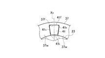
- FIG. 3B is a partial plan view of the tapered roller and the support as viewed in the axial direction.
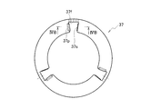
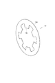
- FIG. 4A is a plan view of a support based on an example as viewed in an axial direction.
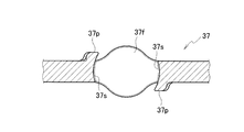
- FIG. 4B is a partial cross-sectional view of the support taken from line VIB-VIB of FIG. 4A.
- FIG. 5 is a partial plan view of a tapered roller and a support based on another example as viewed in the axial direction.
- FIG. 6A is a cross-sectional view of a pressure plate, a cam ball, and a cam plate according to an example using a cam ball.
- FIG. 6B is a partial plan view of the cam ball and the support as viewed in the axial direction.
- FIG. 7 is a perspective view of the disc spring.
- the axis means the rotating shaft of the cam mechanism, and the axial direction is a direction parallel to this, and the radial direction is a direction orthogonal to this, and Direction means the direction of rotation about the axis.
- the cam mechanism 3 can be applied to, for example, the clutch device 1 illustrated in FIG. 1, but is not necessarily limited to this.
- the clutch device 1 is a device that intermittently or controls transmission of torque between a first rotating body and a second rotating body that rotate around an axis X.
- the first rotating body is a clutch.
- the case 21 is the case, and the second rotating body is the shaft 23.
- the clutch device 1 generally includes a cam mechanism 3, means 27 for operating the cam mechanism 3, a friction clutch 25, and a spring 13 for pushing the cam mechanism back to an initial position.
- a friction clutch 25 is interposed between the clutch case 21 and the shaft 23 to mediate torque transmission.
- the friction clutch 25 is a multi-plate clutch, but may be another type of friction clutch.
- a plurality of outer plates of the clutch 25 are connected to the clutch case 21 by lugs and the like, and a plurality of inner plates alternately arranged with the outer plates are connected to the shaft 23 by lugs and the like.
- the cam mechanism 3 exerts an axial force on the clutch 25, the outer plate and the inner plate are frictionally connected, and torque is transmitted between the clutch case 21 and the shaft 23. Further, the torque transmitted is increased or decreased by increasing or decreasing the axial force.
- the clutch device 1 also includes a means 27 for generating a differential to operate the cam mechanism 3, and the means 27 generally includes a pilot clutch 29 and a solenoid 31 for operating the pilot clutch 29.
- the means 27 actuate the cam mechanism by braking the cam plate 35, in this example, relative to the pressure plate 39.
- the pilot clutch 29 is also a multi-plate clutch in this example, but may be another type of friction clutch.
- the plurality of outer plates of the pilot clutch 29 are connected to the clutch case 21 by lugs and the like, and the plurality of inner plates alternately arranged with the outer plates are connected to the cam plate 35 by lugs and the like.
- the solenoid 31 further includes a core 32 that guides the magnetic flux but has a gap, and an armature 33 that is arranged so as to straddle the gap.
- the core 32 and the armature 33 are arranged so as to sandwich the pilot clutch 29. I have.
- the solenoid 31 When the solenoid 31 is excited, the magnetic flux attracts the armature 33 toward the core 32, so that friction occurs between the outer plate and the inner plate to brake the cam plate 35. That is, when there is an angular velocity difference between the clutch case 21 and the shaft 23, the cam plate 35 generates a differential with respect to the pressure plate 39 accordingly.
- the cam mechanism 3 generally includes a cam plate 35, a pressure plate 39, a plurality of rolling elements interposed therebetween, and an annular support for supporting the rolling elements. 37.
- the example of the rolling element is the taper roller 41, but may be a ball as described later, or may have another appropriate shape.
- the cam plate 35 is rotatable about the axis X and is connected to the inner plate of the means 27 by a lug or the like so as to receive the differential as described above.
- the cam plate 35 is provided with a cam surface 35c in contact with the rolling surface 41 R of the tapered roller 41.
- the cam surface 35c is slightly inclined in the circumferential direction with respect to the circumferential surface orthogonal to the axis X so that the taper roller 41 rolls and moves in the axial direction.
- the pressure plate 39 is also rotatable about the axis X, is opposed to the cam plate 35 in the axial direction, and is also opposed to the clutch 25 in the axial direction so as to press the clutch 25 and is movable in the axial direction. Also, it is engaged with the shaft 23 so as to rotate with the shaft 23. Therefore, the cam plate 35 generates a differential with respect to the pressure plate 39 when braking.
- the pressure plate 39 also comprises a cam surface 39c in contact with the rolling surface 41 R of the tapered roller 41.
- the cam surface 39c is also slightly inclined in the circumferential direction with respect to the circumferential surface orthogonal to the axis X so that the pressure plate 39 is moved in the axial direction by the rolling of the taper roller 41.
- the inclination may be given to only one of the cam surface 35c and the cam surface 39c.
- the plurality of tapered rollers 41 are symmetrically arranged with respect to the axis X.
- the number of the tapered rollers 41 is three in the illustrated example, but is not limited to this. Three or more is preferable from the viewpoint of maintaining the parallelism between the plates 35 and 39, but too many usually do not contribute to the burden of the axial force.
- Each tapered roller 41 is directed as along the radial axis X R orthogonal to the axis X, a side in the rolling contact surface 41 R of rolling over it in contact with the cam surface 35c, 39c as shown in FIG. 3A is there.
- Such rolling surface 41 R is rotationally symmetrical with respect to the radiation axis X R, also forms a tapered such conical surface toward the radially inward.
- Rolling surface 41 R and the cam surface 35c, contact with 39c may be substantially its entire length across line contact. This helps the cam mechanism 3 to bear a large axial force and provides a moderate resistance to rolling. This resistance is braking to the initial movement of the cam mechanism 3 as described later.
- each taper roller 41 the outer peripheral surface 41f facing outward in the radial direction comes into contact with and is supported by the support 37.
- the outer peripheral surface 41f may be separated from the cam plate 35 and the pressure plate 39.
- the inner peripheral surface 41i may be separated from any of the plates 35 and 39, the support 37, and the shaft 23, or may be supported in contact with the support 37 as shown in FIG.
- the support 37 is generally annular and most of it is a disk portion 37w having a constant thickness.
- the disk portion 37w is cut out or punched out at equal intervals in the circumferential direction to form a notch for accommodating the taper roller 41, and the inner surfaces thereof are a support surface 37f and a holding surface 37s.
- Support surface 37f abuts on the outer peripheral surface 41f of the tapered roller 41, the holding surface 37s is in contact with the rolling surface 41 R.
- the support surface 37f and the holding surface 37s are dimensioned to be in close contact with each other to prevent the tapered roller 41 from falling off, and may be dimensioned to be in frictional contact with each other for resistance to rolling. Such resistance can also act as a brake to the initial movement of the cam mechanism 3.
- the support 37 can further include a claw 37p that protrudes mainly in the axial direction from the disk portion 37w so as to extend the holding surface 37s.
- the taper roller 41 overcomes the elasticity of the claw 37p and snaps into the notch, and thereafter the claw 37p prevents the taper from falling off. Further, the claw 37p can increase the resistance to the rolling of the taper roller 41 by extending the holding surface 37s.
- the support 37 may protrude from the disk portion 37w on the outer periphery thereof so as to enlarge the area of the support surface 37f.
- the enlarged support surface 37f is advantageous in supporting the radially outward pressing force applied to the tapered roller 41, and can increase the resistance of the tapered roller 41 to rolling.
- the support 37 moves in both the circumferential direction and the axial direction as the taper roller 41 rolls on the cam surfaces 35c and 39c to move up and down, respectively, so that the support 37 continues to support the taper roller 41.
- the plurality of disk portions 37w of the support 37 are fitted to the shaft 23 at radially inner ends. Such a fit allows the support 37 to move in the axial direction, but is at least frictional to create resistance to rotational movement. This not only helps to align the taper roller 41 and the support 37 with respect to the axis X, but also resists the operation of the cam, so that the cam mechanism 3 exerts an unintended pressing force on the pressure plate 39 as a result. Hinder.
- a structure, a member, or a coating that increases friction at least in the rotation direction may be interposed between the disk portion 37w and the shaft 23. In order to increase the contact area with the shaft 23, the disk portion 37w may be continuous inside the inner peripheral surface 41i of the tapered roller 41 as shown in FIG.
- the rolling element may be a cam ball 41B as shown in FIGS. 6A and 6B instead of the roller.
- Rolling surface 41 R of the cam ball 41B may be a rotationally symmetric spherical surface.
- Support 37 is provided with a circular hole in response to the rolling surface 41 R.
- the inner surface of the circular hole is supported surface 37f, which is sized so as to contact closely to the rolling surface 41 R of the cam ball 41B, also optionally be dimensioned as possible contact with the frictional the resistance to rolling Good.
- a so-called disc spring can be used as the spring 13.
- the disc spring is not limited to one, and may be a plurality of stacked disc springs.
- the entire spring 13 has a conical dish shape slightly inclined from the outer edge toward the center, and has a hole near the center, that is, a truncated cone.
- Only the outer edge portion 13d may be a perfect cone, or the inner peripheral portion may be cut out to form a plurality of tab portions 13p.
- the inner end of the tab portion 13p is supported by a stationary member, and exerts elasticity at the outer edge of the outer edge portion 13d.
- Such a shape is advantageous for exhibiting a constant elastic force over a relatively long stroke, and the characteristics are unlikely to change even if the tab portion 13p and the outer edge portion 13d are slightly worn.
- the spring 13 abuts any one of the shafts 23 on the inner circumference, for example, the snap ring 15 engaged with a lug for the inner plate, and abuts on the outer edge, for example, the pressure plate 39. It is urged away from the friction clutch 25. When the axial force by the cam mechanism 3 is released, the spring 13 pushes the pressure plate 39 back to the initial position, thereby preventing the friction clutch 25 from being dragged.
- Pressing the pressure plate 39 evenly at the outer edge of the spring 13 has an advantage in maintaining the parallelism between the plates 35 and 39, and also has an advantage in that the pressure plate 39 presses the friction clutch 25 evenly. .
- the cam mechanism 3 when an unintended drag occurs on the pilot clutch 29, the cam mechanism 3 operates unintentionally and presses the pressure plate 39 toward the friction clutch 25.
- the spring 13 presses the pressure plate 39 in a direction opposite thereto, but does not oppose the pressing force applied only by the elastic force of the spring 13.
- Several resistive elements including a support 37 frictionally fitted to the shaft 23, inhibit initial movement of the cam mechanism 3 and cooperate with the spring 13 to prevent unintended dragging.
- the clutch device 1 according to the present embodiment also contributes to the fuel saving of the vehicle in terms of electric power consumption.
Landscapes
- Engineering & Computer Science (AREA)
- General Engineering & Computer Science (AREA)
- Mechanical Engineering (AREA)
- Physics & Mathematics (AREA)
- Electromagnetism (AREA)
- Mechanical Operated Clutches (AREA)
- Transmission Devices (AREA)
Abstract
La présente invention concerne un dispositif d'embrayage (1) pour commander la transmission d'un couple entre un premier corps rotatif (21) et un second corps rotatif (23) capables chacun de se mettre en rotation autour d'un axe, ledit dispositif d'embrayage comprenant : une plaque de came (35) pourvue d'une première surface de came (35c) et apte à se mettre en rotation autour de l'axe par rapport au second corps rotatif (23) ; un embrayage pilote (29) relié à la plaque de came (35) de manière à freiner la plaque de came (35) dans la direction circonférentielle par rapport au premier corps rotatif (21) ; une plaque de pression (39) qui est pourvue d'une seconde surface de came (39c) faisant face à la première surface de came (35c) dans la direction axiale et qui peut se mettre en rotation conjointement avec le second corps rotatif (23) et se déplacer dans la direction axiale ; une pluralité de corps de roulement (41) pour rouler conformément à un mouvement différentiel de la plaque de came (35) par rapport à la plaque de pression (39), les corps de roulement (41) étant intercalés entre la plaque de came (35) et la plaque de pression (39) ; un support (37) qui forme un anneau autour de l'axe et supporte de manière rotative chacun de la pluralité de corps de roulement (41) et limite leur roulement, le support (37) étant monté à ajustement serré avec le second corps rotatif (23) de façon à générer une résistance contre un mouvement dans la direction de rotation ; et un embrayage à friction (25) pour transmettre un couple entre le premier corps rotatif (21) et le second corps rotatif (23) lorsqu'il est pressé axialement sur la plaque de pression (39).
Priority Applications (3)
| Application Number | Priority Date | Filing Date | Title |
|---|---|---|---|
| CN201880095168.1A CN112352114B (zh) | 2018-07-02 | 2018-07-02 | 摩擦离合器装置 |
| JP2020528556A JP7065189B2 (ja) | 2018-07-02 | 2018-07-02 | 摩擦クラッチ装置 |
| PCT/JP2018/025079 WO2020008507A1 (fr) | 2018-07-02 | 2018-07-02 | Dispositif d'embrayage à friction |
Applications Claiming Priority (1)
| Application Number | Priority Date | Filing Date | Title |
|---|---|---|---|
| PCT/JP2018/025079 WO2020008507A1 (fr) | 2018-07-02 | 2018-07-02 | Dispositif d'embrayage à friction |
Publications (1)
| Publication Number | Publication Date |
|---|---|
| WO2020008507A1 true WO2020008507A1 (fr) | 2020-01-09 |
Family
ID=69060779
Family Applications (1)
| Application Number | Title | Priority Date | Filing Date |
|---|---|---|---|
| PCT/JP2018/025079 Ceased WO2020008507A1 (fr) | 2018-07-02 | 2018-07-02 | Dispositif d'embrayage à friction |
Country Status (3)
| Country | Link |
|---|---|
| JP (1) | JP7065189B2 (fr) |
| CN (1) | CN112352114B (fr) |
| WO (1) | WO2020008507A1 (fr) |
Citations (5)
| Publication number | Priority date | Publication date | Assignee | Title |
|---|---|---|---|---|
| JP2005344920A (ja) * | 2004-06-07 | 2005-12-15 | Tochigi Fuji Ind Co Ltd | トルク伝達機構 |
| JP2008248937A (ja) * | 2007-03-29 | 2008-10-16 | Jtekt Corp | 駆動力伝達装置 |
| JP2013064472A (ja) * | 2011-09-20 | 2013-04-11 | Jtekt Corp | 駆動力伝達装置 |
| JP2016061350A (ja) * | 2014-09-17 | 2016-04-25 | Ntn株式会社 | ローラカム機構、回転伝達装置およびステアバイワイヤ方式の車両用操舵装置 |
| WO2017149829A1 (fr) * | 2016-03-04 | 2017-09-08 | Gkn ドライブライン ジャパン株式会社 | Mécanisme à came et dispositif d'embrayage utilisant ledit mécanisme à came |
Family Cites Families (11)
| Publication number | Priority date | Publication date | Assignee | Title |
|---|---|---|---|---|
| JP4006960B2 (ja) * | 2001-06-08 | 2007-11-14 | 株式会社ジェイテクト | 電磁パイロット式クラッチ装置の製造方法 |
| JP4010839B2 (ja) * | 2002-03-25 | 2007-11-21 | 株式会社ショーワ | 動力切換装置 |
| US6790153B2 (en) * | 2002-12-04 | 2004-09-14 | Ntn Corporation | Roller clutch assembly |
| JP2006125495A (ja) * | 2004-10-28 | 2006-05-18 | Gkn ドライブライン トルクテクノロジー株式会社 | 電磁クラッチ及び動力伝達装置 |
| JP2009019743A (ja) * | 2007-07-13 | 2009-01-29 | Gkn ドライブライン トルクテクノロジー株式会社 | 動力伝達装置 |
| JP2010127294A (ja) * | 2008-11-25 | 2010-06-10 | Ntn Corp | プーリユニット |
| JP2011122680A (ja) * | 2009-12-11 | 2011-06-23 | Jtekt Corp | 電磁クラッチ |
| FR2969242B1 (fr) * | 2010-12-16 | 2013-07-05 | Peugeot Citroen Automobiles Sa | Dispositif de transmission de couple, et boite de vitesses le comportant |
| JP6135035B2 (ja) * | 2011-09-26 | 2017-05-31 | 株式会社ジェイテクト | 電磁クラッチ |
| JP5951215B2 (ja) * | 2011-10-13 | 2016-07-13 | 株式会社ジェイテクト | クラッチ装置 |
| JP6020060B2 (ja) * | 2012-11-09 | 2016-11-02 | 株式会社ジェイテクト | 伝達トルク推定装置 |
-
2018
- 2018-07-02 WO PCT/JP2018/025079 patent/WO2020008507A1/fr not_active Ceased
- 2018-07-02 CN CN201880095168.1A patent/CN112352114B/zh not_active Expired - Fee Related
- 2018-07-02 JP JP2020528556A patent/JP7065189B2/ja active Active
Patent Citations (5)
| Publication number | Priority date | Publication date | Assignee | Title |
|---|---|---|---|---|
| JP2005344920A (ja) * | 2004-06-07 | 2005-12-15 | Tochigi Fuji Ind Co Ltd | トルク伝達機構 |
| JP2008248937A (ja) * | 2007-03-29 | 2008-10-16 | Jtekt Corp | 駆動力伝達装置 |
| JP2013064472A (ja) * | 2011-09-20 | 2013-04-11 | Jtekt Corp | 駆動力伝達装置 |
| JP2016061350A (ja) * | 2014-09-17 | 2016-04-25 | Ntn株式会社 | ローラカム機構、回転伝達装置およびステアバイワイヤ方式の車両用操舵装置 |
| WO2017149829A1 (fr) * | 2016-03-04 | 2017-09-08 | Gkn ドライブライン ジャパン株式会社 | Mécanisme à came et dispositif d'embrayage utilisant ledit mécanisme à came |
Also Published As
| Publication number | Publication date |
|---|---|
| CN112352114B (zh) | 2022-02-15 |
| JP7065189B2 (ja) | 2022-05-11 |
| JPWO2020008507A1 (ja) | 2021-05-13 |
| CN112352114A (zh) | 2021-02-09 |
Similar Documents
| Publication | Publication Date | Title |
|---|---|---|
| US11402006B2 (en) | Differential device | |
| US7980371B2 (en) | Selectable mode clutch | |
| US6257386B1 (en) | Power cut/connect device | |
| JP2002195311A (ja) | 二方向クラッチ | |
| US9133891B2 (en) | Friction clutch plate, friction clutch and driving force transmission apparatus | |
| EP4048914B1 (fr) | Plaque d'induit flexible pour un embrayage à roue libre électromagnétique | |
| WO2022219827A1 (fr) | Dispositif de mise en prise par frottement | |
| WO2020008507A1 (fr) | Dispositif d'embrayage à friction | |
| TW201837332A (zh) | 離合器摩擦片以及離合器裝置 | |
| KR101664579B1 (ko) | 자동변속기의 리턴스프링 공용 구조 | |
| CN103267069B (zh) | 离合器装置 | |
| JP6298777B2 (ja) | ディスクブレーキ装置 | |
| JP2004239406A (ja) | クラッチ装置 | |
| JP2012062937A (ja) | 電磁クラッチ及びこれを備えた駆動力伝達装置 | |
| JP2008248937A (ja) | 駆動力伝達装置 | |
| JPH03199722A (ja) | 2方向差動クラッチ | |
| WO2019171459A1 (fr) | Mécanisme de came à faible hystérésis pourvu de rouleaux coniques | |
| JP2004239405A (ja) | クラッチ装置 | |
| WO2018061626A1 (fr) | Dispositif d'embrayage de motocyclette | |
| JP4686952B2 (ja) | 駆動力伝達装置 | |
| JP2004239311A (ja) | 摩擦クラッチ | |
| JP2005351296A (ja) | 摩擦係合装置のフリクションプレート | |
| KR101315532B1 (ko) | 구동력 전달시스템 | |
| JP2008075802A (ja) | クラッチプレート、摩擦クラッチ及び駆動力伝達装置 | |
| JP2012122563A (ja) | 係合装置 |
Legal Events
| Date | Code | Title | Description |
|---|---|---|---|
| 121 | Ep: the epo has been informed by wipo that ep was designated in this application |
Ref document number: 18925368 Country of ref document: EP Kind code of ref document: A1 |
|
| ENP | Entry into the national phase |
Ref document number: 2020528556 Country of ref document: JP Kind code of ref document: A |
|
| NENP | Non-entry into the national phase |
Ref country code: DE |
|
| 122 | Ep: pct application non-entry in european phase |
Ref document number: 18925368 Country of ref document: EP Kind code of ref document: A1 |