WO2017149900A1 - ラベル貼付機構、ラベル貼付装置及びラベル貼付方法 - Google Patents
ラベル貼付機構、ラベル貼付装置及びラベル貼付方法 Download PDFInfo
- Publication number
- WO2017149900A1 WO2017149900A1 PCT/JP2016/087370 JP2016087370W WO2017149900A1 WO 2017149900 A1 WO2017149900 A1 WO 2017149900A1 JP 2016087370 W JP2016087370 W JP 2016087370W WO 2017149900 A1 WO2017149900 A1 WO 2017149900A1
- Authority
- WO
- WIPO (PCT)
- Prior art keywords
- label
- adherend
- unit
- sticking
- holding
- Prior art date
- Legal status (The legal status is an assumption and is not a legal conclusion. Google has not performed a legal analysis and makes no representation as to the accuracy of the status listed.)
- Ceased
Links
Images


Classifications
-
- B—PERFORMING OPERATIONS; TRANSPORTING
- B65—CONVEYING; PACKING; STORING; HANDLING THIN OR FILAMENTARY MATERIAL
- B65C—LABELLING OR TAGGING MACHINES, APPARATUS, OR PROCESSES
- B65C3/00—Labelling other than flat surfaces
-
- B—PERFORMING OPERATIONS; TRANSPORTING
- B65—CONVEYING; PACKING; STORING; HANDLING THIN OR FILAMENTARY MATERIAL
- B65C—LABELLING OR TAGGING MACHINES, APPARATUS, OR PROCESSES
- B65C9/00—Details of labelling machines or apparatus
- B65C9/26—Devices for applying labels
- B65C9/36—Wipers; Pressers
Definitions
- the present invention relates to a label attaching mechanism for attaching a label to an adherend, a label attaching apparatus provided with this label attaching mechanism, and a label attaching method for attaching a label to an adherend.
- an adherend In the fields of product manufacture, management, distribution, etc., information on the product is visibly printed and attached to the product, or a label attached directly to an object such as the product (hereinafter referred to as an adherend). Is used.
- JP2008-239227A includes a suction plate having a suction surface for sucking a label, a pressing member that presses the label via a sheet member, and a pressing member that is interposed between the pressing member and the label.
- a label affixing device having a sheet member that is pressed to press a label against an article is disclosed.
- the label sticking device of Patent Document 1 when a roller as a pressing member is pressed against an article via a sheet member and the roller rolls according to the curvature of the cylindrical surface of the article, the label is moved by the sheet member to the cylindrical surface of the article. Is pushed along. Thereby, a label can be stuck to an article having a cylindrical surface without causing wrinkles.
- a label application device due to the diversification of the packages described above, it is more difficult to apply labels with a label application device.
- a package in which food is enclosed in a packaging material in a vacuum state hereinafter referred to as a vacuum pack
- the packaging material since the packaging material is in close contact with the food, the shape of the enclosed food is directly reflected in the surface shape of the package.
- a label pasting region is usually provided at the edge portion of the exterior material that does not reach the enclosed food.
- a label sticking device for sticking a label, a label sticking mechanism for sticking the label to an adherend, a sticking transport section for transporting the label, and the label A control unit that controls a sticking mechanism, wherein the label sticking mechanism has a holding part that holds the label with an adhesive surface facing the adherend side, and a transport surface of the sticking transport part.
- a label sticking device comprising: a pressing part that presses down an adherend; and a driving part that drives the holding part so that the adhesive surface of the label is in contact with the adherend pressed by the pressing part.
- the holding portion that holds the adhesive surface of the label having an adhesive surface toward the adherend, and the placement surface on which the adherend is placed.
- a label sticking mechanism having a pressing part that presses the adherend, and a drive part that drives the holding part so that the adherend surface of the label comes into contact with the adherend pressed by the pressing part.
- a label affixing method for affixing a label to an adherend to be continuously conveyed wherein identification information for identifying the adherend is acquired from the adherend to be conveyed, and based on the acquired identification information Position information relating to the label application area on the adherend, correcting the acquired position information on the application area based on the identification information, and controlling the drive unit based on the corrected position information.
- the label Labeling method of attaching the urging region is provided.
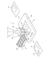
- FIG. 1 is a perspective view for explaining a label sticking mechanism according to an embodiment of the present invention.
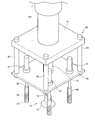
- FIG. 2 is an enlarged perspective view showing a main part of the label sticking mechanism according to the embodiment of the present invention.
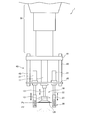
- FIG. 3 is a side view of the label sticking mechanism according to the embodiment of the present invention.
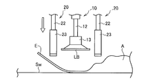
- FIG. 4 is a side view showing a state in which the label sticking mechanism descends toward the adherend while holding the label.
- FIG. 5 is a side view showing a state immediately before the label sticking mechanism sticks the label to the adherend.
- FIG. 6 is a side view showing the state when the label attaching mechanism attaches a label to the adherend.
- FIG. 1 is a perspective view for explaining a label sticking mechanism according to an embodiment of the present invention.
- FIG. 2 is an enlarged perspective view showing a main part of the label sticking mechanism according to the embodiment of the present invention.
- FIG. 3 is a side view of the label sticking mechanism according to the embodiment of the present invention.
- FIG. 4 is
- FIG. 1 is a perspective view for explaining a label attaching mechanism 1 according to an embodiment of the present invention.
- FIG. 2 is an enlarged perspective view showing a main part of the label sticking mechanism 1.
- FIG. 3 is a side view of the label sticking mechanism 1.
- the label sticking mechanism 1 is a device that sticks a label LB to a specific region of the adherend A placed on the placement surface Sw of the placement table W.
- the area to which the label LB is affixed is represented as an affixed area AL, and is indicated by a broken line in FIG.
- the adherend A is a package in which food is sealed in a vacuum state in an exterior material (hereinafter referred to as a vacuum pack).
- a vacuum pack since the outer packaging material is in close contact with the food, the shape of the enclosed food is directly reflected on the surface shape of the package. For this reason, the sticking area AL of the adherend is provided at the edge portion of the exterior material that does not reach the enclosed food.
- the label LB describes information on the food enclosed in the adherend A, such as the date of manufacture, the date of thawing, the expiration date, and the like.
- the label LB is transported to the vicinity of the label sticking mechanism 1 by the transport belt C.
- the conveyance surface of the conveyance belt C is subjected to a non-adhesion process in which the adhesion surface of the label LB is difficult to adhere.
- the label sticking mechanism 1 includes a holding unit 10 that holds the label LB with the adhesive surface facing the adherend A side, and a pressing unit 20 that holds the adherend A toward the placement surface Sw. And a drive unit 30 that drives the holding unit 10.
- the holding unit 10 and the pressing unit 20 are attached to the driving unit 30 via a bracket 40.
- the holding unit 10 includes a holding unit mount 11 attached to the bracket 40, a holding unit rod 12 connected to the holding unit mount 11, and a suction cup 13 attached to the tip of the holding unit rod 12.
- the holding part mount 11 and the holding part rod 12 are made of metal.
- the holder mount 11 is provided with a mechanism (not shown) for moving the holder rod 12 in the normal direction of the placement surface Sw (hereinafter also referred to as a pressing direction).
- the suction cup 13 is made of a flexible material. As the flexible material, rubber or synthetic resin is preferable.
- the suction force of the suction cup 13 is set to be weaker than the adhesive force of the label LB.
- a plane including the position P1 of the end portion in contact with the label LB of the suction cup 13 is referred to as a holding surface.
- the pressing portion 20 includes a pressing portion mount 21 attached to the bracket 40, a pressing portion rod 22 connected to the pressing portion mount 21, and a tip end portion 23 connected to the pressing portion rod 22.
- the pressing part mount 21 and the pressing part rod 22 are made of metal.
- the tip portion 23 is formed in a bottomed cylindrical shape. The outer bottom surface of the tip portion 23 constitutes a contact surface that contacts the adherend A.
- the drive unit 30 includes an actuator that can be driven in the vertical direction and horizontal direction of the mounting table W and in the normal direction (pressing direction) of the mounting surface Sw.
- the drive unit 30 includes an actuator that drives in a rotation direction about the normal line of the placement surface Sw. Accordingly, the driving unit 30 drives the holding unit 10 and the pressing unit 20 in a space extending over the conveyance surface of the conveyance belt C, the conveyance surface of the conveyance belt C, the placement surface Sw, and the placement surface Sw. can do.
- the drive unit 30 has a holding surface that holds the label in the holding unit 10 at a position advanced from a reference surface including a contact surface that contacts the adherend A of the pressing unit 20 and a position retracted from the reference surface.
- the drive unit 30 sets the position P1 of the end (holding surface) of the suction cup 13 in the holding unit 10 to the position P2 ( It is set at a position advanced to the placement surface Sw side in the normal direction of the placement surface Sw than the reference surface).
- the holding surface is set at this position.
- the bracket 40 includes a drive unit side support plate 41 attached to the drive unit 30, an adherend side support plate 42 to which the holding unit mount 11 and the pressing unit mount 21 are attached, and the drive unit side support plate 41 and the adherend side.
- a connecting member 43 that connects the support plate 42 is provided.
- the drive unit side support plate 41, the adherend side support plate 42, and the connecting member 43 are all made of metal.
- the drive unit side support plate 41 and the adherend side support plate 42 have a rectangular shape, and are connected to each other by connecting members 43 at the four corners.
- the holding portion mount 11 is attached to the center portion of the adherend-side support plate 42. Further, four pressing portion mounts 21 are attached to the periphery of the central portion of the adherend-side support plate 42.
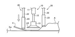
- FIG. 4 is a side view showing a state in which the label sticking mechanism 1 descends toward the adherend A while holding the label LB.
- FIG. 5 is a side view showing a state immediately before the label applying mechanism 1 applies the label LB to the adherend A.
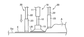
- FIG. FIG. 6 is a side view showing a state when the label attaching mechanism 1 attaches the label LB to the adherend A.
- FIGS. 4 to 6 show the state of the edge portion E of the adherend A in which the labeling area AL of the label LB is set.
- the label sticking mechanism 1 is configured such that the position P1 of the end portion of the suction cup 13 is closer to the placement surface Sw side than the position P2 of the outer bottom surface of the tip portion 23 in the normal direction of the placement surface Sw.
- the label LB is sucked and held from the transport belt C in the state where the head is advanced forward. Since the conveyance surface of the conveyance belt C is subjected to non-adhesive processing, even if the label LB is disposed in a state where the adhesion surface is in contact with the conveyance surface, the holding unit 10 is able to remove the label LB by the suction force of the suction cup 13. Can be easily taken up from the conveyor belt C.
- the drive unit 30 makes the position P1 of the end of the suction cup 13 a normal direction of the placement surface Sw rather than the position P2 of the outer bottom surface of the front end portion 23 of the holding unit 20. At the bracket 40 side.
- the drive unit 30 moves the bracket 40 in the normal direction of the placement surface Sw so that the position P1 of the end portion of the suction cup 13 is more than the position P2 of the outer bottom surface of the distal end portion 23 of the pressing unit 20.
- the holding part 10 and the pressing part 20 are lowered toward the adherend A in a state of being retracted to the side.
- the holding unit 10 and the pressing unit 20 are moved above the placement surface Sw. Since the suction force of the suction cup 13 is set to be weaker than the adhesive strength of the label LB, the label LB is released from the suction cup 13 without following the movement of the suction cup 13.
- the sticking defect which arises when a part of the to-be-adhered body A in which the sticking area
- the outer bottom surface of the tip portion 23 is pressed against the placement surface Sw before the label LB held by the holding unit 10, and then the label LB is affixed to the adherend A. Therefore, after the outer bottom surface of the tip portion 23 has surely pressed the sticking area of the adherend A against the mounting surface Sw, the adhesive surface of the label LB contacts the adherend A, so that the label LB is attached to the adherend A. Can be securely attached.
- the label sticking mechanism 1 according to the present embodiment can be variously modified without departing from the gist of the present invention.
- the holding unit 10 may be connected to a suction mechanism that generates negative pressure, and may be configured to adsorb the label LB using the generated negative pressure. That is, the holding part 10 may be formed with a suction part. It is preferable that the negative pressure can be turned on and off at the timing when the label LB is picked up from the conveying belt C and the timing when the label LB is released after being attached to the adherend A. Since such a suction part is formed in the holding part 10, the label LB can be surely taken up and held by suction, and the label LB can be released smoothly after the label LB is stuck to the adherend A. It can be carried out.
- the buffering property of the holding part 10 can be further increased, and when the label LB is taken up from the transport belt C or when the label LB is applied to the adherend A, The effect of not damaging the label LB and the adherend A is further enhanced.
- the holding part 10 is a suction part
- the suction part of the holding part 10 is adsorbed to the label LB
- the label LB may be twisted or wrinkled by a sudden negative pressure.
- the bellows structure is combined, the suction force applied to the label LB is buffered by the contraction of the bellows part 51 when the suction part of the holding part 10 is attracted to the label LB. This can prevent the label LB from being twisted or wrinkled.
- the label LB can be released smoothly by turning off the suction.
- the four pressing parts 20 provided in the label sticking mechanism 1 according to the present embodiment may be detachably attached to each other.
- the pressing part 20 since the pressing part 20 is formed so as to be detachable, the user of the label sticking mechanism 1 leaves the pressing part 20 at a position corresponding to a desired area in the adherend A, and other than the corresponding part.
- the pressing portion 20 can be removed. Thereby, the food enclosed in the vacuum pack can be protected. Moreover, the required location in the to-be-adhered body A can be suppressed exactly.
- FIGS. 8 to 10 are enlarged views of a main part for explaining a modification example of a portion of the pressing portion that contacts the label LB.
- the portion that contacts the label LB is shaped so that the cross-sectional area that intersects the normal direction decreases as the normal direction of the mounting surface Sw moves toward the mounting surface Sw. Can do.
- the pressing portion 60 shown in FIG. 8 has a spherical portion 61 formed in a contact portion with the label LB. According to this configuration, the contact area with the adherend A can be reduced. Thereby, even if the surface of the adherend A is uneven, the adherend A can be reliably pressed toward the placement surface Sw.
- the structure may be such that the normal direction of the mounting surface Sw is tapered toward the mounting surface Sw side.
- the elastic member 71 further has a bellows portion 72.
- the elastic member 71 at the contact portion with the label LB, it is possible to prevent the adherend A from being damaged when the adherend A is pressed toward the placement surface Sw. it can.
- the elastic member 71 when it is pressed against the adherend A, it also has an anti-slip effect. Thereby, the adherend A can be reliably pressed toward the placement surface Sw.
- the adherend A is described as a vacuum pack.
- the adherend A is not limited to a vacuum pack.
- a package in which a tray in which food is stored is covered with a transparent film, a package in which an outer packaging material is formed in a cylindrical shape and food is stored and both ends of the opening of the cylinder are sealed may be used.
- the user can change the position of the pressing part 20 so as to correspond to the area to be pressed on the plane including the pasting area of the adherend A, or freely set the intervals between the plurality of pressing parts 20. Can be set. Thereby, even if there is a difference in the shape of the adherend A to which the label LB is attached and the crease of the adherend A, the necessary portion of the adherend A can be surely pressed, and the label LB can be covered. Can be reliably affixed to the body A.
- the length of the long holes 44a, 44b, and 44c, the positions to be formed, and the number are not limited to the example described in FIG.
- a plurality of mounting holes to which the pressing portion mount 21 can be attached may be formed in the adherend-side support plate 42.
- a plurality of mounting holes may be formed concentrically from the center of the adherend-side support plate 42.
- the label sticking device is a label sticking device for sticking a label, and controls a label sticking mechanism for sticking a label to an adherend, a sticking transport unit for transporting the label, and a label sticking mechanism.
- a label sticking mechanism a holding part that holds the label with the adhesive surface facing the adherend side, and a pressing part that presses the sticking area of the adherend toward the transport surface of the sticking transport part; And a drive unit that drives the holding unit so that the adhesive surface of the label comes into contact with the pasting region of the adherend pressed by the pressing unit.
- the sticking transport unit 101 transports the adherend A to which the label LB is pasted by the label pasting mechanism 1.
- the label LB can be pasted while the adherend A is being transported by the pasting transport unit 101.
- the feeding transport unit 102 feeds the adherend A to the pasting transport unit 101.
- the conveyance speeds of the sticking conveyance unit 101 and the loading conveyance unit 102 are appropriately adjusted by a controller described later. Details of the control of the conveyance speed will be described later.
- the upstream imaging unit 103 is arranged on the upstream side of the label attaching mechanism 1 and images the adherend A before attaching the label LB.
- the image data picked up by the upstream image pickup unit 103 is used for the determination process of the pasting area where the label LB is pasted.
- the downstream imaging unit 104 is arranged on the downstream side of the label pasting mechanism 1 and images the adherend A after pasting the label LB.
- the image data acquired by the downstream imaging unit 104 is used to generate an error signal that notifies an error in the label LB application state.
- the printer unit 110 includes a printer main body 111 that prints information about the adherend A on a label LB, a label roll 112 in which the label LB before printing is temporarily attached to a continuous body of the mount, and a continuous body of the mount.
- the label sticking apparatus 100 includes the printer unit 110, so that information on the adherend A (food) can be printed on the label LB immediately before sticking.
- the printer unit 110 is connected to an information processing apparatus such as a personal computer (PC) (not shown), and receives input of information related to the adherend A (food) from the user, or sets the printer itself. Can do.
- PC personal computer
- FIG. 13 is a schematic configuration diagram of the label sticking device 100.
- the label sticking device 100 controls the drive of the sticking drive motor 201 and the sticking drive motor 201 as shown in FIG.
- the label sticking device 100 includes a vertical actuator 211, a horizontal actuator 212, a height actuator 213, a rotation direction actuator 214, and each of the actuators that constitute the drive unit 30 provided in the label sticking mechanism 1.
- the vertical actuator 211 is an actuator that drives in the transport direction of the sticking transport unit 101.
- the lateral actuator 212 is an actuator that drives in a direction that intersects the transport direction of the sticking transport unit 101.
- the height direction actuator is an actuator that drives in the normal direction of the conveyance surface of the sticking conveyance unit 101.
- the rotation direction actuator 214 is an actuator that drives in the rotation direction about the normal line of the conveyance surface of the sticking conveyance unit 101.
- the label sticking device 100 controls the drive of the holding part actuator 215 that drives the holding part 10 provided in the label sticking mechanism 1 in the normal direction of the conveyance surface of the sticking conveyance part 101 and the holding part actuator. And an actuator controller 225.
- the label sticking device 100 has a storage device 230.
- the storage device 230 stores a control program for executing a process (described later) for determining a pasting area where the label LB is pasted on the adherend A based on the acquired image data.
- identification information for identifying the adherend A and information related to the paste area of the label LB that differs for each adherend A are associated with the determination process of the paste area.
- the table is stored.
- the storage device 230 stores a control program for executing processing for adjusting the transport speed of the sticking transport unit 101 and the transport speed of the loading transport unit 102. The identification information for identifying the adherend A will be described later.
- the label sticking apparatus 100 includes a controller 240 that performs overall control of each configuration described above.
- controller 240 will be described.
- the controller 240 executes the control program stored in the storage device 230 in the microprocessor, thereby pasting each adherend A on the basis of the image data acquired from the upstream imaging unit 103 via the input / output interface. A process for determining an area is executed.
- the controller 240 executes a process of adjusting the conveyance speed of the sticking conveyance unit 101 and the conveyance speed of the loading conveyance unit 102 by executing a control program stored in the storage device 230 in the microprocessor.
- the controller 240 executes the control program stored in the storage device 230 in the microprocessor, thereby comparing the pasting position of the label LB after pasting acquired by the downstream imaging unit 104 with the determined pasting area. If the degree of departure from the determined pasting area exceeds the threshold, processing for notifying an error message is performed by a not-shown notification unit.
- the controller 240 is connected to the printer unit 110 via an input / output interface, adjusts the conveyance speed of the sticking conveyance unit 101 and the conveyance speed of the loading conveyance unit 102, and performs printing in the printer unit 110. It is possible to generate a control signal for stopping the operation or temporarily stopping the conveyance of the label LB.
- the process for determining the label LB application area refers to the identification information for identifying the adherend A from the conveyed adherend A and the label application area on the adherend A based on the acquired identification information.
- the position information is acquired, the position information of the obtained pasting area is corrected based on the identification information, and the drive unit 30 is controlled based on the corrected position information to stick the label LB to the pasting area.
- the identification information of the adherend A is the product name of the food described in the package which is the adherend A, the position of the product name column in which the product name is described, the shape of the column, the size of the column, and the background color. , Character color, etc.
- these pieces of information described in the package are used as identification information.
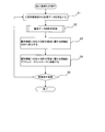
- FIG. 14 is a flowchart showing the contents of the pasting area determination process for each adherend A based on the image data, which is executed by the controller 240.
- step S1 the controller 240 acquires identification information of the adherend A. That is, the controller 240 receives image data obtained by imaging the adherend A from the upstream imaging unit 103.
- step S2 the controller 240 executes an analysis process on the acquired image data. Details of the analysis processing will be described later.
- the controller 240 extracts identification information by analysis processing.
- step S3 the controller 240 extracts position information related to the pasting region associated with the identification information from the storage device 230. That is, the controller 240 accesses the storage device 230 and extracts position information related to the pasting region corresponding to the identification information of the adherend A obtained as a result of the analysis processing in step S2 based on the stored table. To do. In addition, the controller 240 corrects the extracted position information based on the obtained identification information, and generates an actuator control signal based on the corrected position information.
- step S5 the controller 240 determines whether or not there is a subsequent adherend A. If there is a subsequent adherend A, the controller 240 repeats from step S1, and if there is no subsequent adherend A, the process is performed. finish.
- FIGS. 15 and 16 are schematic views for explaining the package of the adherend A used in the present embodiment.
- the contents to be printed on the exterior material of the adherend A are determined based on specific rules. For example, the position, shape, size, etc. of the product name column are unified for each product name of the food enclosed in the adherend A. Also, a predetermined background color and character color are used in the product name column. These rules can be used as identification information for identifying the adherend A by providing rules for the position, shape, size, background color, character color, etc. of these product name fields. And the sticking area
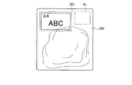
- FIG. 15 shows an example of a package of an adherend 300.
- a product name column 301 on which product name ABC is printed and a pasting area AL are shown.
- the pasting area AL is a broken line frame, the broken line frame is not printed on the actual adherend.
- Position information relating to the broken line frame is defined by position information based on the product name column.
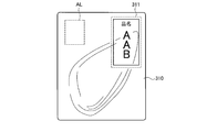
- FIG. 16 shows an example of a package of another adherend 310.
- a product name column 311 on which product name AAB is printed and a pasting area AL are shown.
- the position information regarding the pasting area AL indicated by the broken line frame is defined by the position information based on the product name column.
- a table that associates the product name, the position information of the product name column, and the position information of the pasting area AL with reference to the product name column is stored in the storage device 230 for each food enclosed in the adherend A. Keep it.
- the controller 240 can extract the position information of the contour of the adherend 300 and the position information of the product name column 301 with respect to the contour by analyzing the acquired image data. . Further, the controller 240 extracts the position information of the pasting area AL corresponding to this position information from the storage device 230. Further, the controller 240 corrects the position information of the pasting area AL extracted from the storage device 230 based on the position information of the actual product name column 301 obtained by the analysis, and generates an actuator control signal.
- the label sticking apparatus 100 can stick the label LB to the sticking area AL of the adherend A that is continuously conveyed. Further, as described above, the label sticking apparatus 100 corrects the position information of the extracted sticking area AL based on the position information in the actual product name column 301 obtained by the analysis, and generates the actuator control signal. Therefore, for example, even when the adherend A is placed so that the rotation angles about the normal line of the transport surface are different from each other, the label LB can be attached to the correct application region AL.
- the pasted position of the pasted label LB and the storage device 230 are extracted from the image data of the adherend A including the pasted label acquired by the downstream imaging unit 104.
- the difference (degree of deviation) can be calculated by comparing the position information obtained by correcting the position information of the pasting area AL. By setting a threshold value for the difference, when the threshold value is exceeded, it can be notified as a pasting error.
- the controller 240 controls the feeding speed of the feeding transport section 102 to be synchronized with the transport speed of the sticking transport section 101 in a normal state.
- T1 Time from when the label applying device 100 applies the label LB to the adherend A, to acquire the next label LB, and after the acquisition, the time until the label LB is applied to the next adherend A
- T2 Time from application of the label LB to the adherend A until the next label LB enters the drivable region of the label application device 100.
- T1 and T2 satisfy T1 ⁇ T2.
- the controller 240 sets, in the normal state satisfying T1 ⁇ T2, a transport position on the pasting transport unit 101 when the label LB is pasted on the adherend A, on the upstream side of the pasting transport unit 101.
- the controller 240 determines that the timing when the label LB is pasted to the pasting area AL of the adherend A by the label pasting mechanism 1 is the transport for pasting. In accordance with the transition to the downstream side in the transport direction of the part 101, the transport speed of the feeding transport part 102 is controlled to be slower than the transport speed of the sticking transport part 101.
- the controller 240 further reduces the speed of the sticking conveyance unit.
- the controller 240 By performing such a stepwise adjustment process of the conveyance speed, it is possible to reliably adhere the label LB to the adherend A while maintaining the speed of the adhesion conveying unit 101 as much as possible. Further, by maintaining the speed of the sticking transport unit 101 as much as possible, it is possible to prevent a reduction in work efficiency.
- the label sticking apparatus 100 includes a label sticking mechanism 1 for sticking the label LB to the adherend A, a sticking transport unit 101 for transporting the label LB, and a controller 240 for controlling the label sticking mechanism 1. And have.
- the label sticking device 100 uses the label sticking mechanism 1 to direct the adherend A toward the placement surface Sw by the pressing portion 20 even when the sticking area of the adherend A is lifted from the placement surface Sw.
- the label LB can be attached to the adherend A in a pressed state. For this reason, according to the label sticking apparatus 100 according to the present embodiment, the label LB is attached to the adherend A while preventing the sticking failure caused by the sticking area of the adherend A floating from the placement surface Sw.
- the affixing operation can be performed continuously.
- the label sticking device 100 includes a printer unit 110 that prints information about the adherend A, and the label sticking mechanism 1 sticks a printed label LB printed by the printer unit 110 to the adherend A, thereby Since the label LB having information corresponding to the adherend A can be prepared immediately before the work of attaching the adherend A to the adherend A, work efficiency is improved.
- the label sticking apparatus 100 can determine the sticking area of the label LB corresponding to the adherend A based on the identification information of the adherend A being conveyed. For this reason, the label sticking apparatus 100 can continuously perform the work of sticking the label LB at an accurate position for each adherend A. Moreover, since the label sticking apparatus 100 uses the label sticking mechanism 1, it is possible to prevent sticking defects caused by the sticking area of the adherend A being lifted from the placement surface Sw.
- the label sticking device 100 includes a vertical actuator 211, a horizontal actuator 212, a height actuator 213, a rotation direction actuator 214, and a rotation direction actuator 214 that constitute the drive unit 30 provided in the label sticking mechanism 1.
- Actuator controllers 221, 222, 223, and 224 for controlling the driving of each actuator are provided.
- the label sticking apparatus 100 reliably maintains the label LB while maintaining the speed of the sticking transport unit 101 as much as possible. Can be affixed to the adherend A.
Landscapes
- Labeling Devices (AREA)
Abstract
本発明の実施形態に係るラベル貼付機構は、ラベルを保持する保持部と、被着体を載置面に向けて押さえる押さえ部と、保持部を駆動する駆動部とを有する。ラベル貼付機構において、保持部及び押さえ部は、ブラケットを介して駆動部に取り付けられている。
Description
本発明は、被着体にラベルを貼り付けるラベル貼付機構、このラベル貼付機構を備えたラベル貼付装置、及び被着体にラベルを貼り付けるラベル貼付方法に関する。
製品の製造、管理、流通等の分野では、製品に関する情報が視認可能に印字されて製品に取り付けられるタグや、製品などの対象物(以下、被着体という)に、直接、貼付されるラベルが用いられる。
被着体にラベルを貼付する作業には、ラベル貼付装置が用いられており、これまでにも、ラベルに皺が発生しないように、ラベルを被着体の表面形状に追従させて貼付する技術が提案されている(JP2008-239227A参照)。
JP2008-239227Aには、ラベルを吸引する吸着面を有する吸着板と、シート部材を介してラベルを押さえる押さえ部材と、押さえ部材とラベルとの間に介在し、吸着板の貼付位置で押さえ部材に押されてラベルを物品に対して押圧するシート部材を有するラベル貼付装置が開示されている。特許文献1のラベル貼付装置では、押さえ部材としてのローラがシート部材を介して物品に押圧されて、ローラが物品の円柱面の曲率に応じて転動すると、ラベルがシート部材によって物品の円柱面に沿って押し付けられる。これにより、円柱面を有する物品に対して、皺を生じさせることなくラベルを貼付できる。
食品業界では、被着体である食品のパッケージの形態は多様化している。例えば、食品が収められたトレーが透明フィルムで覆われたパッケージ、外装材が筒状に形成されており食品が収められて筒の開口両端を封止してなるパッケージ、深絞り成形された樹脂製容器に食品が収められたパッケージ、食品が外装材に真空状態で封入されたパッケージ等がある。
また、上述したパッケージの多様化により、ラベル貼付装置によるラベルの貼付も困難性が増している。特に、食品が外装材に真空状態で封入されたパッケージ(以下、真空パックという)では、外装材が食品に密着するため、封入された食品の形状がそのままパッケージの表面形状に反映される。このため、被着体が真空パックの場合には、通常、封入された食品が及ばない外装材の縁部分にラベルの貼付領域が設けられている。
しかし、真空パックの縁部分は、箱詰めによる輸送や保管を経ることにより、折れ曲がり易い。このため、真空パックを載置面に置いた際に、載置面から縁部分が浮き上がるような折り癖がつくことがあった。ラベルの貼付領域に折り癖がつくと、ラベル貼付装置による貼付エラーが発生し易くなる。このため、被着体が真空パックの場合には、縁部分に折り癖がつかないように箱詰めする配慮や、ラベル貼付装置への投入前に折り癖を直す人為的な手間が必要であった。このように、被着体の状態によっては、ラベル貼付装置による貼付作業の効率が低下するため、ラベル貼付装置には依然として改良の余地があった。
そこで、本発明は、被着体の貼付領域に確実にラベルを貼付できるようにすることを目的とする。
本発明のある態様によれば、ラベルを貼付するラベル貼付機構であって、粘着面を被着体側に向けて前記ラベルを保持する保持部と、前記被着体が載置された載置面に向けて前記被着体を押さえる押さえ部と、前記押さえ部によって押さえられた前記被着体に前記ラベルの前記粘着面が当接するように前記保持部を駆動する駆動部とを有するラベル貼付機構が提供される。
また、本発明の別の態様によれば、ラベルを貼付するラベル貼付装置であって、前記ラベルを被着体に貼付するラベル貼付機構と、前記ラベルを搬送する貼付用搬送部と、前記ラベル貼付機構を制御する制御部とを有し、前記ラベル貼付機構は、粘着面を前記被着体側に向けて前記ラベルを保持する保持部と、前記貼付用搬送部の搬送面に向けて前記被着体を押さえる押さえ部と、前記押さえ部によって押さえられた前記被着体に前記ラベルの前記粘着面が当接するように前記保持部を駆動する駆動部と、を有するラベル貼付装置が提供される。
さらに、本発明の別の態様によれば、粘着面を有するラベルの前記粘着面を前記被着体側に向けて保持する保持部と、前記被着体が載置される載置面に向けて前記被着体を押さえる押さえ部と、前記押さえ部によって押さえられた前記被着体に前記ラベルの前記粘着面が当接するように前記保持部を駆動する駆動部とを有するラベル貼付機構を用いて、連続して搬送される被着体にラベルを貼付するラベル貼付方法であって、搬送される前記被着体から前記被着体を識別する識別情報を取得し、前記取得した識別情報に基づいて前記被着体における前記ラベルの貼付領域に関する位置情報を取得し、前記取得した貼付領域の位置情報を前記識別情報に基づいて補正し、補正後の位置情報に基づいて前記駆動部を制御して、前記ラベルを前記貼付領域に貼付するラベル貼付方法が提供される。
これらの態様によれば、被着体の貼付領域に確実にラベルを貼付できる。
[ラベル貼付機構]
本発明の実施形態に係るラベル貼付機構は、ラベルを貼付するラベル貼付機構であって、粘着面を被着体側に向けて前記ラベルを保持する保持部と、前記被着体が載置された載置面に向けて前記被着体を押さえる押さえ部と、前記押さえ部によって押さえられた前記被着体に前記ラベルの前記粘着面が当接するように前記保持部を駆動する駆動部とを有する。
本発明の実施形態に係るラベル貼付機構は、ラベルを貼付するラベル貼付機構であって、粘着面を被着体側に向けて前記ラベルを保持する保持部と、前記被着体が載置された載置面に向けて前記被着体を押さえる押さえ部と、前記押さえ部によって押さえられた前記被着体に前記ラベルの前記粘着面が当接するように前記保持部を駆動する駆動部とを有する。
以下、ラベル貼付機構について、図面を参照して詳細に説明する。また、図面において、同様の機能を有する構成については、同一の番号を付して詳細な説明は省略する。
図1は、本発明の実施形態に係るラベル貼付機構1を説明する斜視図である。図2は、ラベル貼付機構1の要部を拡大して示す斜視図である。図3は、ラベル貼付機構1の側面図である。図1に示すように、ラベル貼付機構1は、載置台Wの載置面Swに載置された被着体Aの特定の領域にラベルLBを貼付する装置である。本実施形態においては、ラベルLBが貼付される領域を、貼付領域ALと表し、図1では破線で記載されている。
本実施形態において、被着体Aとは、食品が外装材に真空状態で封入されたパッケージである(以下、真空パックという)。真空パックでは、外装材が食品に密着するため、封入された食品の形状がそのままパッケージの表面形状に反映される。このため、被着体の貼付領域ALは、封入された食品が及ばない外装材の縁部分に設けられる。
ラベルLBとは、本実施形態では、被着体Aに封入された食品に関する情報、例えば、製造年月日、解凍年月日、消費期限等が記載されたものである。本実施形態では、ラベルLBは、搬送ベルトCによってラベル貼付機構1の近傍まで搬送される。搬送ベルトCの搬送面には、ラベルLBの粘着面が粘着し難い非粘着加工が施されている。
図1に示すように、ラベル貼付機構1は、粘着面を被着体A側に向けてラベルLBを保持する保持部10と、被着体Aを載置面Swに向けて押さえる押さえ部20と、保持部10を駆動する駆動部30とを有する。ラベル貼付機構1において、保持部10及び押さえ部20は、ブラケット40を介して駆動部30に取り付けられている。
以下、各部の構成について説明する。図2に示すように、保持部10は、ブラケット40に取り付けられる保持部マウント11と、保持部マウント11に連結された保持部ロッド12と、保持部ロッド12の先端に取り付けられた吸盤13とを備える。保持部マウント11及び保持部ロッド12は、金属製である。保持部マウント11には、保持部ロッド12を載置面Swの法線方向(以下、押さえ方向という場合がある)に動かす機構(図示しない)が備えられている。吸盤13は、可撓性材料で形成されている。可撓性材料としては、ゴム又は合成樹脂が好ましい。吸盤13の吸着力は、ラベルLBの粘着力よりも弱く設定されている。吸盤13のラベルLBと接触する端部の位置P1が含まれる平面を保持面という。
押さえ部20は、ブラケット40に取り付けられる押さえ部マウント21と、押さえ部マウント21に連結された押さえ部ロッド22と、押さえ部ロッド22に連結された先端部分23とを備える。押さえ部マウント21及び押さえ部ロッド22は、金属製である。先端部分23は、有底筒状に形成されている。先端部分23の外側底面は、被着体Aに当接する当接面を構成している。
また、押さえ部ロッド22の端部と先端部分23の内側底面との間には、弾性部材として、コイルバネ24が配置されている。このコイルバネ24が押し縮められたり、伸張したりすることにより、押さえ部ロッド22に対して先端部分23を押さえ方向に動かすことができる。したがって、押さえ部20は、押さえ方向に伸縮自在に形成されている。
本実施形態に係るラベル貼付機構1は、4つの押さえ部20を有する。押さえ部20は、保持部10にラベルLBが保持された状態で、ラベルLBの外縁よりも外側に配置されている。これにより、押さえ部20は、被着体Aにおいて、ラベルLBが貼付される貼付領域ALの周囲を押さえることができる。
駆動部30は、図示しないが、載置台Wの縦方向、横方向及び載置面Swの法線方向(押さえ方向)に駆動することのできるアクチュエータを備える。また、駆動部30は、載置面Swの法線を軸とする回動方向に駆動するアクチュエータを備える。これにより、駆動部30は、搬送ベルトCの搬送面、搬送ベルトCの搬送面上方、載置面Swの上方、及び載置面Swに亘る空間内において、保持部10及び押さえ部20を駆動することができる。
駆動部30は、保持部10においてラベルを保持する保持面を、押さえ部20の被着体Aに当接する当接面を含む基準面よりも前進した位置と、基準面よりも後退した位置とに駆動する。具体的には、図3に示されるように、駆動部30は、保持部10における吸盤13の端部(保持面)の位置P1を、押さえ部20の先端部分23の外側底面の位置P2(基準面に相当する)よりも、載置面Swの法線方向において、載置面Sw側に前進した位置にセットする。ラベルLBを搬送ベルトCから取り上げる際には、保持面は、この位置にセットされる。また、駆動部30は、保持部10における吸盤13の端部の位置P1を、押さえ部20の先端部分23の外側底面の位置P2よりも、ブラケット40側に後退した位置にセットする。ラベルLBを保持した状態では、保持面は、この位置にセットされる。
ブラケット40は、駆動部30に取り付けられた駆動部側支持板41と、保持部マウント11及び押さえ部マウント21が取り付けられた被着体側支持板42と、駆動部側支持板41と被着体側支持板42とを連結する連結部材43とを備える。駆動部側支持板41、被着体側支持板42及び連結部材43は、いずれも金属製である。駆動部側支持板41及び被着体側支持板42は、矩形状を有し、その四隅において連結部材43によって互いに連結されている。被着体側支持板42の中央部には、保持部マウント11が取り付けられている。また、被着体側支持板42の中央部の周辺には、4つの押さえ部マウント21が取り付けられている。
続いて、上述した構成を有するラベル貼付機構1の動作について説明する。
図4は、ラベル貼付機構1がラベルLBを保持した状態で、被着体Aに向けて下降する様子を示した側面図である。図5は、ラベル貼付機構1がラベルLBを被着体Aに貼付する直前の様子を示した側面図である。図6は、ラベル貼付機構1が被着体AにラベルLBを貼付したときの様子を示した側面図である。図4~図6には、ラベルLBの貼付領域ALが設定されている被着体Aの縁部分Eの様子が示されている。
ラベル貼付機構1は、図3に示したように、吸盤13の端部の位置P1が先端部分23の外側底面の位置P2よりも、載置面Swの法線方向において、載置面Sw側に前進した状態で、搬送ベルトCからラベルLBを吸着して保持する。搬送ベルトCの搬送面には非粘着加工が施されているため、ラベルLBが粘着面を搬送面に接する状態で配置されていても、保持部10は、吸盤13の吸着力によって、ラベルLBを搬送ベルトCから容易に取り上げることができる。
搬送ベルトCからラベルLBを吸着した後は、駆動部30は、吸盤13の端部の位置P1を押さえ部20の先端部分23の外側底面の位置P2よりも、載置面Swの法線方向においてブラケット40側に後退させる。
続いて、駆動部30は、図4に示すように、吸盤13の端部の位置P1を押さえ部20の先端部分23の外側底面の位置P2よりも載置面Swの法線方向においてブラケット40側に後退させた状態で、保持部10及び押さえ部20を被着体Aに向けて下降させる。
このため、図5に示すように、駆動部30が保持部10をラベルLBが被着体Aに貼付される位置まで下降させる際、先端部分23の外側底面は、吸盤13の端部に先行して、載置面Swから浮き上がった縁部分E又は載置面Swよりも高くなった被着体Aの表面に接する。駆動部30は、先端部分23の外側底面が縁部分Eに接した後も、吸盤13に保持されたラベルLBが被着体Aに貼付されるまでブラケット40を下降させる。このとき、押さえ部20は、コイルバネ24が押し縮められながら、押さえ方向に伸縮される。
これにより、図5に示すように、載置面Swよりも浮き上がった被着体Aの縁部分E及び載置面Swよりも高くなった被着体Aの表面が、先端部分23の外側底面によって載置面Swに向けて押さえられ、更に、図6に示すように載置面Swに押さえ付けられた状態で、ラベルLBが被着体Aに貼付される。
ラベルLBが被着体Aに貼付された後、保持部10及び押さえ部20は、載置面Swの上方に移動される。吸盤13の吸着力は、ラベルLBの粘着力よりも弱く設定されているため、ラベルLBは、吸盤13の移動に追従することなく、吸盤13から解放される。
次に、上述した本実施形態に係るラベル貼付機構1の作用効果について説明する。
上述した本実施形態に係るラベル貼付機構1は、粘着面を被着体A側に向けてラベルLBを保持する保持部10と、載置面Swに向けて被着体Aを押さえる押さえ部20と、押さえ部20によって押さえられた被着体Aの貼付領域にラベルLBの粘着面が当接するように保持部10を駆動する駆動部30とを有することにより、ラベルLBの貼付領域ALが含まれた被着体Aの一部が載置面Swから浮き上がっていても、押さえ部20によって、被着体Aを載置面Swに向けて押さえられた状態で被着体Aの貼付領域ALにラベルLBを貼付できる。このため、本実施形態に係るラベル貼付機構1によれば、ラベルLBの貼付領域ALが含まれた被着体Aの一部が載置面Swから浮き上がっていることにより生じる貼付不良を防止できる。
また、保持部10のラベルLBと当接する部分、すなわち、吸盤13は、可撓性材料で形成されている。これにより、ラベルLBを搬送ベルトCから取り上げる際、或いは、被着体AにラベルLBを貼付する際に、吸盤13がラベルLBに押しつけられても、ラベルLBを損傷することがない。さらには、被着体Aを損傷することがない。これらの観点から、吸盤13は、ゴム材料から形成されていることが好ましい。
また、押さえ部20は、押さえ方向に伸縮可能に形成されている。また、駆動部30は、ラベルLBを搬送ベルトCから取り上げる際には、保持部10における吸盤13の端部(保持面)の位置P1を、押さえ部20の先端部分23の外側底面の位置P2(基準面に相当する)よりも、載置面Swの法線方向において、ブラケット40側に前進した位置にセットし、ラベルLBを保持した状態では、保持部10における吸盤13の端部の位置P1を、押さえ部20の先端部分23の外側底面の位置P2よりも、後退した位置にセットする。
これにより、ラベルLBが貼付される直前では、先端部分23の外側底面が保持部10に保持されたラベルLBに先行して被着体Aを載置面Swに向けて押さえ、続いて、ラベルLBが被着体Aに貼付される。したがって、先端部分23の外側底面が被着体Aの貼付領域を載置面Swに確実に押しつけた後に、ラベルLBの粘着面が被着体Aに当接するため、ラベルLBを被着体Aに確実に貼付することができる。
また、ラベル貼付機構1には、4つの押さえ部20が設けられている。これにより、押さえ部20は、被着体AのラベルLBの貼付領域ALの周囲を確実に押さえることができる。また、押さえ部20は、ラベルLBが保持部10に保持された状態で、ラベルLBの縁部分よりも外側に設けられている。これにより、押さえ部20は、保持部10に保持されたラベルLBに干渉することなく、且つ被着体AのラベルLBの貼付領域ALの周囲を確実に押さえることができる。
[ラベル貼付機構の変形例]
本実施形態に係るラベル貼付機構1は、本発明の要旨を逸脱しない範囲で種々の変更が可能である。
本実施形態に係るラベル貼付機構1は、本発明の要旨を逸脱しない範囲で種々の変更が可能である。
保持部10は、負圧を生成する吸引機構に接続されており、生成した負圧を利用してラベルLBを吸着する構成になっていてもよい。すなわち、保持部10には、吸引部が形成されていてもよい。ラベルLBを搬送ベルトCから取り上げるタイミングと、ラベルLBを被着体Aに貼付した後の解放のタイミングとで、負圧のオンオフが自在になっていることが好ましい。保持部10に、このような吸引部が形成されていることにより、吸引により確実にラベルLBを取り上げて保持できるとともに、ラベルLBを被着体Aに貼付した後のラベルLBの解放もスムーズに行うことができる。
保持部10において、ラベルLBに当接する部分は、可撓性材料から形成されており、更に蛇腹構造を有していてもよい。図7は、保持部におけるラベルLBに当接する部分の変形例を説明する要部拡大図である。図7に示すように、変形例として示す保持部50のラベルLBとの当接部分には、蛇腹部51及び吸盤52が形成されている。図面において、同様の機能を有する構成については、同一の番号を付している。保持部50が蛇腹部51を備えることにより、保持部10の緩衝性を一層高めることができ、ラベルLBを搬送ベルトCから取り上げる際、或いは、被着体AにラベルLBを貼付する際において、ラベルLBや被着体Aを損傷しないという効果が一層高められる。
上述した吸引機構を備えた吸引部と蛇腹構造とを組み合わせることもできる。保持部10が吸引部の場合には、保持部10の吸引部がラベルLBに吸着した際に、急激な負圧によって、ラベルLBに撚れ又は皺が生じ得る。これに対して、蛇腹構造が組み合わされていると、保持部10の吸引部がラベルLBに吸着した際に、蛇腹部51が収縮することにラベルLBにかかる吸着力が緩衝される。これにより、ラベルLBに撚れ又は皺ができることを防止できる。また、被着体Aに貼付した後で、吸引をオフにすることにより、ラベルLBの解放もスムースに行える。
本実施形態に係るラベル貼付機構1に設けられた4つの押さえ部20は、それぞれが着脱可能に取り付けられていてもよい。例えば、真空パックに封入された食品のサイズや形状によっては、封入された食品の一部が特定の位置にある押さえ部20によって押される頻度が高くなる状況が起こりうる。これに対して、押さえ部20が着脱可能に形成されていることにより、ラベル貼付機構1のユーザは、被着体Aにおける所望の領域に対応する位置にある押さえ部20を残し、該当箇所以外の押さえ部20を取り外すことができる。これにより、真空パックに封入された食品を保護することができる。また、被着体Aにおける必要箇所を的確に押さえることができる。
図8~10は、押さえ部におけるラベルLBに当接する部分の変形例を説明する要部拡大図である。押さえ部20において、ラベルLBに当接する部分は、載置面Swの法線方向を載置面Sw側に向かうに連れて、法線方向に交差する断面積が小さくなるような形状とすることができる。このような構造の一例として、図8に示す押さえ部60は、ラベルLBとの当接部分に、球状部分61が形成されている。この構成によれば、被着体Aとの接触面積を小さくできる。これにより、被着体Aの表面が凸凹していても、被着体Aを載置面Swに向けて確実に押さえることができる。同様の構造として、載置面Swの法線方向を載置面Sw側に向かうに連れて先細りになった構造であってもよい。
図9に示す押さえ部70は、ラベルLBとの当接部分が弾性部材71で形成されている。弾性部材71は、さらに蛇腹部分72を有している。このように、ラベルLBとの当接部分に弾性部材71が設けられていることにより、被着体Aを載置面Swに向けて押さえる際に、被着体Aの損傷を防止することができる。また、弾性部材71とすることにより、被着体Aに押し当てられた際に、滑り止めの効果も奏する。これにより、被着体Aを載置面Swに向けて確実に押さえることができる。
図10に示す押さえ部80は、ラベルLBとの当接部分に、複数の押さえ部80の先端同士を連結してなる枠状部分81が形成されている。枠状部分81は、硬質材料から形成されていてもよいし、可撓性材料で形成されていてもよい。貼付領域の近傍に食品が及んでいる場合などにおける被着体Aの表面形状への追従性の観点から、可撓性材料からなることが好ましい。ラベルLBとの当接部分に、枠状部分81が設けられていることによって、被着体Aの貼付領域の周辺を載置面Swに向けて確実に押さえることができる。
本実施形態において、被着体Aは真空パックであるとして説明した。しかし、被着体Aは、真空パックに限定されない。例えば、食品が収められたトレーが透明フィルムで覆われたパッケージ、外装材が筒状に形成されており食品が収められて筒の開口両端を封止してなるパッケージ等であってもよい。
図11は、被着体側支持板の変形例を示す構成図である。図11に示す被着体側支持板44は、被着体側支持板の各辺に平行に形成された長孔44a,44b,44cを有する。被着体側支持板44では、押さえ部マウント21が長孔44a,44b,44cに沿って、載置面Swに対して平行方向に移動自在に取り付けられる。
このようにすることで、ユーザは、被着体Aの貼付領域を含む平面において、押さえたい領域に対応するように押さえ部20の位置を変更したり、複数の押さえ部20の間隔を自由に設定したりできる。これにより、ラベルLBが貼付される被着体Aの形状や、被着体Aの折り癖の違いがあっても、被着体Aの必要箇所を確実に押さえることができ、ラベルLBを被着体Aに確実に貼付できる。なお、長孔44a,44b,44cの長さ、形成される位置、及び数は、図11に記載された例示に限定されない。
このほかに、被着体側支持板42には、押さえ部マウント21を取り付けることのできる複数の取付用ホールが形成されていてもよい。例えば、被着体側支持板42の中央から同心円状に複数の取付用ホールが形成されていてもよい。
[ラベル貼付装置]
次に、本発明の実施形態に係るラベル貼付装置について説明する。
次に、本発明の実施形態に係るラベル貼付装置について説明する。
本実施形態に係るラベル貼付装置は、ラベルを貼付するラベル貼付装置であって、ラベルを被着体に貼付するラベル貼付機構と、ラベルを搬送する貼付用搬送部と、ラベル貼付機構を制御する制御部とを有し、ラベル貼付機構は、粘着面を被着体側に向けてラベルを保持する保持部と、貼付用搬送部の搬送面に向けて被着体の貼付領域を押さえる押さえ部と、押さえ部によって押さえられた被着体の貼付領域にラベルの粘着面が当接するように保持部を駆動する駆動部と、を有する。以下、本発明に係るラベル貼付装置について、図面を参照して詳細に説明する。
図12は、本発明の実施形態に係るラベル貼付装置100を説明する斜視図である。図12に示すように、ラベル貼付装置100は、連続して搬送される被着体Aの特定の貼付領域にラベルLBを貼付する装置である。ラベル貼付装置100は、ラベルLBを被着体Aに貼付する上述したラベル貼付機構1と、被着体Aを搬送する貼付用搬送部101と、貼付用搬送部101に被着体Aを投入する投入用搬送部102と、ラベル貼付機構1の上流側に配置された上流側撮像部103と、ラベル貼付機構1の下流側に配置された下流側撮像部104とを有する。また、ラベル貼付装置100は、ラベルLBに被着体Aに封入された食品に関する情報、例えば、製造年月日、解凍年月日、消費期限等を印字するプリンタユニット110を有する。
貼付用搬送部101は、ラベル貼付機構1によってラベルLBを貼付する被着体Aを搬送する。貼付用搬送部101により、被着体Aを搬送しながらラベルLBを貼付することができる。投入用搬送部102は、貼付用搬送部101に被着体Aを投入する。貼付用搬送部101及び投入用搬送部102の搬送速度は、後述するコントローラによって適宜調整されている。搬送速度の制御についての詳細は後述する。
上流側撮像部103は、ラベル貼付機構1の上流側に配置されており、ラベルLBを貼付する前の被着体Aを撮像する。上流側撮像部103によって撮像された画像データは、ラベルLBを貼付する貼付領域の決定処理に使用される。
下流側撮像部104は、ラベル貼付機構1の下流側に配置されており、ラベルLBを貼付した後の被着体Aを撮像する。下流側撮像部104によって取得された画像データは、ラベルLBの貼付状態のエラーを通知するエラー信号の生成に使用される。
プリンタユニット110は、ラベルLBに被着体Aに関する情報を印字するプリンタ本体111と、印字前のラベルLBが台紙の連続体に仮着されてなるラベルロール112と、台紙の連続体から剥離されたラベルLBを搬送する搬送ベルト113と、ラベルLBが剥離された後の台紙の連続体を回収する台紙ロール114を備える。
ラベル貼付装置100は、プリンタユニット110を備えることにより、被着体A(食品)に関する情報を、貼付直前にラベルLBに印字することができる。プリンタユニット110は、図示しないパーソナルコンピュータ(PC)等の情報処理装置に接続されており、ユーザから被着体A(食品)に関する情報の入力を受け付けたり、プリンタ自体の設定等を行ったりすることができる。
次に、ラベル貼付装置100の構成について説明する。図13は、ラベル貼付装置100の概略構成図である。
ラベル貼付装置100は、図12に示す構成を作動させるための構成として、図13に示すように、貼付用搬送部101を駆動する貼付用駆動モータ201と、貼付用駆動モータ201の駆動を制御するコンベアコントローラ202と、投入用搬送部102を駆動する投入用駆動モータ203と、投入用駆動モータ203の駆動を制御するコンベアコントローラ204とを有する。
ラベル貼付装置100は、ラベル貼付機構1に備えられた駆動部30を構成する縦方向アクチュエータ211と、横方向アクチュエータ212と、高さ方向アクチュエータ213と、回動方向アクチュエータ214と、上記の各アクチュエータの駆動をコントロールするアクチュエータコントローラ221,222,223,224とを備える。縦方向アクチュエータ211は、貼付用搬送部101の搬送方向に駆動するアクチュエータである。横方向アクチュエータ212は、貼付用搬送部101の搬送方向に交差する方向に駆動するアクチュエータである。高さ方向アクチュエータとは、貼付用搬送部101の搬送面の法線方向に駆動するアクチュエータである。回動方向アクチュエータ214は、貼付用搬送部101の搬送面の法線を軸とした回動方向に駆動するアクチュエータである。
また、ラベル貼付装置100は、ラベル貼付機構1に備えられた保持部10を貼付用搬送部101の搬送面の法線方向に駆動する保持部アクチュエータ215と、この保持部アクチュエータの駆動をコントロールするアクチュエータコントローラ225とを有する。
ラベル貼付装置100は、記憶装置230を有する。記憶装置230には、取得された画像データに基づいて、被着体AにラベルLBを貼付する貼付領域を決定する処理(後述する)を実行するための制御プログラムが格納されている。また、記憶装置230には、貼付領域の決定処理に関連して、被着体Aを識別するための識別情報と、被着体Aごとに異なるラベルLBの貼付領域に関する情報とが関連付けされたテーブルが記憶されている。また、記憶装置230には、貼付用搬送部101の搬送速度と投入用搬送部102の搬送速度とを調整する処理を実行するための制御プログラムが格納されている。被着体Aを識別するための識別情報については、後段にて説明する。
さらに、ラベル貼付装置100は、上述した各構成を統括制御するコントローラ240を備える。
続いて、コントローラ240について説明する。
コントローラ240は、マイクロプロセッサ、ROM、RAM等の記憶装置、入出力インターフェース、これらを接続するバス等から構成される。コントローラ240は、アクチュエータ(縦方向アクチュエータ211,横方向アクチュエータ212,高さ方向アクチュエータ213、及び回動方向アクチュエータ214)や駆動モータ(貼付用駆動モータ201,投入用駆動モータ203)の制御信号を生成し、入出力インターフェースを介して、各コントローラ(アクチュエータコントローラ221,222,223,224及びコンベアコントローラ202,204)に供給する。
コントローラ240は、記憶装置230に格納された制御プログラムをマイクロプロセッサにおいて実行することにより、入出力インタフェースを介して上流側撮像部103から取得された画像データに基づいて、被着体Aごとに貼付領域を決定する処理を実行する。
コントローラ240は、記憶装置230に格納された制御プログラムをマイクロプロセッサにおいて実行することにより、貼付用搬送部101の搬送速度と投入用搬送部102の搬送速度とを調整する処理を実行する。
コントローラ240は、記憶装置230に格納された制御プログラムをマイクロプロセッサにおいて実行することにより、下流側撮像部104によって取得された貼付後のラベルLBの貼付位置と、決定された貼付領域とを比較して、決定された貼付領域から逸脱する度合いが閾値を超えた場合には、図示しない通知部によりエラーメッセージを通知する処理を実行する。
また、コントローラ240は、入出力インタフェースを介して、プリンタユニット110に接続されており、貼付用搬送部101の搬送速度と投入用搬送部102の搬送速度とを調整するとともに、プリンタユニット110における印字動作の停止や、ラベルLBの搬送を一時的に停止する等の制御信号を生成することができる。
続いて、以下において、コントローラ240がラベルLBの貼付領域を決定する処理について説明する。
ラベルLBの貼付領域を決定する処理とは、搬送される被着体Aから被着体Aを識別する識別情報を取得し、取得した識別情報に基づいて被着体Aにおけるラベルの貼付領域に関する位置情報を取得し、取得した貼付領域の位置情報を識別情報に基づいて補正し、補正後の位置情報に基づいて駆動部30を制御して、ラベルLBを貼付領域に貼付する処理である。
ここで、被着体Aの識別情報とは、被着体Aであるパッケージに記載された食品の品名、また当該品名が記載された品名欄の位置、欄の形状及び欄のサイズ、背景色、文字色等である。本実施形態では、パッケージに記載されたこれらの情報を識別情報として使用する。
図14は、コントローラ240によって実行される、画像データに基づく被着体Aごとの貼付領域の決定処理の内容を示すフローチャートである。
ステップS1において、コントローラ240は、被着体Aの識別情報を取得する。すなわち、コントローラ240は、上流側撮像部103から被着体Aを撮像した画像データを受け取る。
ステップS2において、コントローラ240は、取得した画像データの解析処理を実行する。解析処理の詳細は、後述する。コントローラ240は、解析処理により、識別情報を抽出する。
ステップS3において、コントローラ240は、記憶装置230から識別情報に関連付けされた貼付領域に関する位置情報を抽出する。すなわち、コントローラ240は、記憶装置230にアクセスして、格納されたテーブルに基づいて、ステップS2における解析処理の結果として得られた被着体Aの識別情報に対応する貼付領域に関する位置情報を抽出する。また、コントローラ240は、得られた識別情報に基づいて、抽出した位置情報を補正し、補正後の位置情報に基づくアクチュエータの制御信号を生成する。
ステップS4において、コントローラ240は、貼付領域に関する補正後の位置情報をアクチュエータコントローラ221,222,223,224に供給する。
ステップS5において、コントローラ240は、後続する被着体Aの有無を判別し、後続の被着体Aがある場合には、ステップS1から繰り返し、後続の被着体Aがない場合には処理を終了する。
ここで、ステップS2における画像データの解析処理の一例について、模式図を用いて説明する。図15及び図16は、本実施形態において用いられる被着体Aのパッケージを説明する模式図である。
画像データの解析処理を正確且つ効率的に行うために、被着体Aの外装材に印字する内容を、特定のルールに基づいて決めておく。例えば、被着体Aに封入された食品の品名ごとに、品名欄の位置、形状、サイズ等を統一する。また、品名欄には予め決められた背景色と文字色とを使用する。これらの品名欄の位置、形状、サイズ、背景色、文字色等にルールを設けることによって、これらの情報を被着体Aを識別するための識別情報として使用することができる。そして、被着体AにおけるラベルLBの貼付領域ALを「品名欄」を基準とした位置情報によって決めておく。
図15には、ある被着体300のパッケージの一例が示されている。被着体300には、品名ABCが印字された品名欄301と貼付領域ALとが示されている。貼付領域ALは破線枠にしているが、実際の被着体に破線枠は印字されていない。この破線枠に関する位置情報を、品名欄を基準とする位置情報で規定する。
図16には、別の被着体310のパッケージの一例が示されている。被着体310には、品名AABが印字された品名欄311と貼付領域ALとが示されている。破線枠で示された貼付領域ALに関する位置情報を、品名欄を基準とする位置情報で規定する。
このように、被着体Aに封入される食品ごとに、品名と、品名欄の位置情報と、品名欄を基準とした貼付領域ALの位置情報とを関連付けしたテーブルを記憶装置230に格納しておく。
以上のように準備しておくことにより、コントローラ240は、取得した画像データを解析することにより、被着体300の輪郭の位置情報、この輪郭に対する品名欄301の位置情報を抽出することができる。また、コントローラ240は、この位置情報に対応する貼付領域ALの位置情報を記憶装置230から抽出する。さらに、コントローラ240は、解析によって得られた実際の品名欄301の位置情報に基づいて、記憶装置230から抽出された貼付領域ALの位置情報を補正してアクチュエータの制御信号を生成する。
これにより、ラベル貼付装置100は、連続的に搬送される被着体Aの貼付領域ALにラベルLBを貼付することができる。また、ラベル貼付装置100は、上記説明したように、解析によって得られた実際の品名欄301の位置情報に基づいて、抽出された貼付領域ALの位置情報を補正してアクチュエータの制御信号を生成するため、例えば、被着体Aごとに搬送面の法線を軸とする回転角がそれぞれ異なるように載置されていても、正しい貼付領域ALにラベルLBを貼付することができる。
したがって、ラベル貼付装置100によれば、搬送部において搬送される被着体Aの向きが揃っていなくても、また、被着体Aが搬送面幅方向の中央部に載置されていなくても、確実に貼付領域ALにラベルLBを貼付することができる。また、ラベル貼付装置100によれば、被着体Aが搬送面幅方向の中央部に載置されていなくても、確実に貼付領域ALにラベルLBを貼付することができる。
また、上述した方法によれば、下流側撮像部104によって取得された貼付後のラベルを含む被着体Aの画像データから、貼付後のラベルLBの貼付位置と、記憶装置230から抽出された貼付領域ALの位置情報を補正して得られた位置情報とを比較して、差分(逸脱の度合い)を算出することができる。差分に閾値を設定することにより、閾値を超えた場合には、貼付エラーとして通知することができる。
続いて、以下において、コントローラ240が、貼付用搬送部101の搬送速度と投入用搬送部102の搬送速度とを調整する処理について説明する。
本実施形態に係るラベル貼付装置100では、コントローラ240は、通常状態において、投入用搬送部102の搬送速度を貼付用搬送部101の搬送速度に同調させるように制御している。
ラベル貼付装置100により、滞りなく貼付動作が実行されるためには、下記の条件を満たすことである。すなわち、
T1:ラベル貼付装置100が、被着体AにラベルLBを貼付してから、次のラベルLBを取得しに行き、取得後、次の被着体AにラベルLBを貼付するまでの時間
T2:被着体AにラベルLBを貼付してから、次のラベルLBがラベル貼付装置100の駆動可能領域に入るまでの時間
上記T1とT2とが、T1≦T2を満たすことである。
T1:ラベル貼付装置100が、被着体AにラベルLBを貼付してから、次のラベルLBを取得しに行き、取得後、次の被着体AにラベルLBを貼付するまでの時間
T2:被着体AにラベルLBを貼付してから、次のラベルLBがラベル貼付装置100の駆動可能領域に入るまでの時間
上記T1とT2とが、T1≦T2を満たすことである。
コントローラ240は、T1≦T2を満たす通常状態において、ラベルLBを被着体Aに貼付するときの貼付用搬送部101上の搬送位置を、貼付用搬送部101の上流側に設定しておく。
そして、コントローラ240は、T1とT2とが、T1>T2になった場合には、コントローラ240は、ラベル貼付機構1によりラベルLBを被着体Aの貼付領域ALに貼付するタイミングが貼付用搬送部101における搬送方向下流側に遷移したことに伴って、投入用搬送部102の搬送速度を貼付用搬送部101の搬送速度よりも遅くするよう制御する。
具体的には、コントローラ240は、T1>T2を検出した際、検出後、直ちに貼付用搬送部101の速度を落とさずに、まずは、投入用搬送部102の搬送速度を貼付用搬送部101の搬送速度よりも遅くするように制御する。
T1>T2の条件下においては、投入用搬送部102の搬送速度を貼付用搬送部101の搬送速度よりも遅くしても、ラベルLBが被着体Aに貼付されるときの貼付用搬送部101上の搬送位置が徐々に貼付用搬送部101における下流側に遷移する状況が解消されない場合がある。
この場合には、更に、コントローラ240は、貼付用搬送部の速度を遅くする。このような段階的な搬送速度の調整処理が行われることにより、貼付用搬送部101の速度を可能な限り維持しながら、ラベルLBを被着体Aに確実に貼付することができる。また、貼付用搬送部101の速度を可能な限り維持することで、作業効率の低下を防止することができる。
続いて、上述した本実施形態に係るラベル貼付装置100の作用効果について説明する。
上述した本実施形態に係るラベル貼付装置100は、ラベルLBを被着体Aに貼付するラベル貼付機構1と、ラベルLBを搬送する貼付用搬送部101と、ラベル貼付機構1を制御するコントローラ240とを有する。ラベル貼付装置100は、ラベル貼付機構1を用いることにより、被着体Aの貼付領域が載置面Swから浮き上がっていても、押さえ部20によって、被着体Aを載置面Swに向けて押さえられた状態で被着体AにラベルLBを貼付できる。このため、本実施形態に係るラベル貼付装置100によれば、被着体Aの貼付領域が載置面Swから浮き上がっていることにより生じる貼付不良を防止しつつ、被着体AにラベルLBを貼付する作業を連続的に行うことができる。
ラベル貼付装置100は、被着体Aに関する情報を印字するプリンタユニット110を備え、ラベル貼付機構1は、プリンタユニット110により印字された印字済みラベルLBを被着体Aに貼付することにより、被着体Aに応じた情報を有するラベルLBを被着体Aに貼付する作業の直前に用意することができるため、作業効率が向上する。
ラベル貼付装置100では、被着体Aのパッケージに記載された食品の品名、また当該品名が記載された品名欄の位置、欄の形状及び欄のサイズ、背景色、文字色等の情報を識別情報として使用する。また、ラベル貼付装置100は、この識別情報を取得する上流側撮像部103と、識別情報と被着体Aごとの貼付領域とが関連付けて記憶された記憶装置230と、を有し、コントローラ240は、識別情報に関連付けされたラベルLBの貼付領域に関する位置情報を記憶装置230から取得し、取得した位置情報を、取得した識別情報に基づいて補正し、補正後の位置情報に基づいて駆動部30を制御する。
このように、ラベル貼付装置100は、搬送される被着体Aの識別情報に基づいて、この被着体Aに応じたラベルLBの貼付領域を決定できる。このため、ラベル貼付装置100は、被着体Aごとに正確な位置にラベルLBを貼付する作業を連続的に行うことができる。また、ラベル貼付装置100は、ラベル貼付機構1を用いているので、被着体Aの貼付領域が載置面Swから浮き上がっていることにより生じる貼付不良を防止できる。
また、ラベル貼付装置100は、ラベル貼付機構1に備えられた駆動部30を構成する縦方向アクチュエータ211と、横方向アクチュエータ212と、高さ方向アクチュエータ213と、回動方向アクチュエータ214と、上記の各アクチュエータの駆動をコントロールするアクチュエータコントローラ221,222,223,224とを備える。
これにより、ラベル貼付装置100は、保持部10を自在に駆動することができるとともに、保持部10に保持されたラベルLBの向きを自在に変更できる。したがって、ラベル貼付装置100は、ユーザが貼付用搬送部101に被着体Aを投入する際に、位置決めを厳密に行わなくとも、ラベルLBを被着体Aに確実に貼付できる。
また、ラベル貼付装置100は、ラベルLBが貼付された後の被着体Aを撮像する下流側撮像部104を、更に備え、コントローラ240は、下流側撮像部104によって取得された画像データから、貼付後のラベルLBの貼付位置に関する位置情報を抽出し、貼付後のラベルLBの位置情報が予定された貼付領域から逸脱する度合いを算出し、この逸脱度合いが閾値を超えた場合には、エラーを通知するエラー信号を生成することができる。これにより、ラベル貼付装置100は、仮に貼付エラーが発生した場合であっても、エラーを通知することができる。
また、ラベル貼付装置100は、貼付用搬送部101に向けて被着体Aを投入する投入用搬送部102を備え、コントローラ240は、通常状態において、投入用搬送部102の搬送速度を貼付用搬送部101の搬送速度に同調させるよう制御し、ラベル貼付機構1によりラベルLBを被着体Aの貼付領域に貼付するタイミングが貼付用搬送部101における搬送方向の下流側に遷移したことに伴って、投入用搬送部102の搬送速度を貼付用搬送部101の搬送速度よりも遅くするよう制御する。
これにより、ユーザが被着体Aの投入間隔や投入量等を意図的に調整しなくとも、ラベル貼付装置100は、貼付用搬送部101の速度を可能な限り維持しながら、確実にラベルLBを被着体Aに貼付できる。
[ラベル貼付装置の変形例]
本実施形態に係るラベル貼付装置100は、本発明の要旨を逸脱しない範囲で種々の変更が可能である。上述したラベル貼付機構1の変形例は、本実施形態に係るラベル貼付装置100に対しても適用可能である。
本実施形態に係るラベル貼付装置100は、本発明の要旨を逸脱しない範囲で種々の変更が可能である。上述したラベル貼付機構1の変形例は、本実施形態に係るラベル貼付装置100に対しても適用可能である。
ラベル貼付装置100では、投入用搬送部102の上方に上流側撮像部103が配置されている。しかし、上流側撮像部103の位置は、これに限定されない。貼付用搬送部101の上方にあってもよい。
本実施形態に係るラベル貼付装置100に用いられるプリンタユニット110は一例であって、ラベルLBに印字可能なものであれば適用可能である。
本実施形態に係るラベル貼付装置100に用いられるプリンタユニット110において、印字されるラベルLBは、台紙の連続体に仮着されたものであり、台紙の連続体から剥離されると説明したが、台紙のないタイプであってもよい。すなわち、ラベルが連続体になっており、印字前或いは印字後に切断されて、ラベルLBとして貼付されるタイプであってもよい。
本願は、2016年3月3日に日本国特許庁に出願された特願2016-041509に基づく優先権を主張し、この出願の全ての内容は参照により本明細書に組み込まれる。
Claims (17)
- ラベルを貼付するラベル貼付機構であって、
粘着面を被着体側に向けて前記ラベルを保持する保持部と、
前記被着体が載置された載置面に向けて前記被着体を押さえる押さえ部と、
前記押さえ部によって押さえられた前記被着体に前記ラベルの前記粘着面が当接するように前記保持部を駆動する駆動部と
を有するラベル貼付機構。 - 請求項1に記載のラベル貼付機構であって、
前記押さえ部は、押さえ方向に伸縮可能に形成されているラベル貼付機構。 - 請求項1又は2に記載のラベル貼付機構であって、
前記駆動部は、
前記保持部において前記ラベルを保持する保持面を、
前記押さえ部の前記被着体に当接する当接面を含む基準面よりも前記載置面側に向けて前進した位置と、前記基準面に対して前記載置面とは反対側に後退した位置とに駆動するラベル貼付機構。 - 請求項3に記載のラベル貼付機構であって、
前記駆動部は、
前記ラベルを前記被着体に貼付する際には、
前記保持部において前記ラベルを保持する保持面を、前記基準面よりも後退した位置にセットするラベル貼付機構。 - 請求項1~4のいずれか1項に記載のラベル貼付機構であって、
前記保持部が前記ラベルを吸引する吸引部であるラベル貼付機構。 - 請求項1~5のいずれか1項に記載のラベル貼付機構であって、
前記押さえ部が着脱可能に取り付けられているラベル貼付機構。 - 請求項1~6のいずれか1項に記載のラベル貼付機構であって、
前記押さえ部は、前記載置面に対して平行方向に移動自在に取り付けられるラベル貼付機構。 - 請求項1~7のいずれか1項に記載のラベル貼付機構であって、
前記押さえ部が複数設けられているラベル貼付機構。 - 請求項8に記載のラベル貼付機構であって、
前記複数の押さえ部は、前記保持部に保持される前記ラベルの外縁よりも外側に設けられているラベル貼付機構。 - 請求項1~9のいずれか1項に記載のラベル貼付機構であって、
前記押さえ部の前記被着体と当接する部分が弾性部材で形成されているラベル貼付機構。 - ラベルを貼付するラベル貼付装置であって、
前記ラベルを被着体に貼付するラベル貼付機構と、
前記ラベルを搬送する貼付用搬送部と、
前記ラベル貼付機構を制御する制御部とを有し、
前記ラベル貼付機構は、
粘着面を前記被着体側に向けて前記ラベルを保持する保持部と、前記貼付用搬送部の搬送面に向けて前記被着体を押さえる押さえ部と、前記押さえ部によって押さえられた前記被着体に前記ラベルの前記粘着面が当接するように前記保持部を駆動する駆動部と、
を有するラベル貼付装置。 - 請求項11に記載のラベル貼付装置であって、
前記被着体に関する情報を印字するプリンタを、更に備え、
前記ラベル貼付機構は、前記プリンタにより印字された印字済みラベルを前記被着体に貼付するラベル貼付装置。 - 請求項11又は12に記載のラベル貼付装置であって、
前記被着体は、当該被着体を識別する識別情報を有しており、
前記識別情報を取得する撮像部と、
前記識別情報と、前記被着体ごとに予め決められた前記ラベルを貼付する貼付領域とが関連付けて記憶された記憶部と、を有し、
前記制御部は、前記識別情報に関連付けされた前記貼付領域に関する位置情報を前記記憶部から取得し、前記取得した位置情報を前記取得した識別情報に基づいて補正し、補正後の位置情報に基づいて前記駆動部を制御するラベル貼付装置。 - 請求項11~13のいずれか1項に記載のラベル貼付装置であって、
前記駆動部は、前記保持部を前記搬送面の法線を軸とする回動方向に駆動するアクチュエータと、前記搬送部の搬送方向に駆動するアクチュエータと、前記搬送部の載置面の法線方向に駆動するアクチュエータと、前記搬送方向に直交する方向に駆動するアクチュエータとを備えるラベル貼付装置。 - 請求項11~14のいずれか1項に記載のラベル貼付装置であって、
前記ラベルが貼付された後の被着体を撮像する貼付後撮像部を、更に備え、
前記制御部は、前記貼付後撮像部によって取得された画像データから、貼付後のラベルの貼付位置に関する位置情報を抽出し、前記貼付後のラベルの位置情報が前記貼付領域から逸脱する度合いが閾値を超えた場合には、エラーを通知するエラー信号を生成するラベル貼付装置。 - 請求項11~15のいずれか1項に記載のラベル貼付装置であって、
前記貼付用搬送部に向けて前記被着体を投入する投入用搬送部を、更に備え、
前記制御部は、通常状態において、前記投入用搬送部の搬送速度を前記貼付用搬送部の搬送速度に同調させるよう制御し、
前記ラベル貼付機構により前記ラベルを前記被着体に貼付するタイミングが前記貼付用搬送部における搬送方向の下流側に遷移したことに伴って、前記投入用搬送部の搬送速度を前記貼付用搬送部の搬送速度よりも遅くするよう制御するラベル貼付装置。 - 請求項1~10のいずれか1項に記載されたラベル貼付機構を用いて、連続して搬送される被着体にラベルを貼付するラベル貼付方法であって、
搬送される前記被着体から前記被着体を識別する識別情報を取得し、
前記取得した識別情報に基づいて前記被着体における前記ラベルの貼付領域に関する位置情報を取得し、
前記取得した貼付領域の位置情報を前記識別情報に基づいて補正し、
補正後の位置情報に基づいて前記駆動部を制御して、前記ラベルを前記貼付領域に貼付するラベル貼付方法。
Priority Applications (1)
| Application Number | Priority Date | Filing Date | Title |
|---|---|---|---|
| JP2018502539A JP6941090B2 (ja) | 2016-03-03 | 2016-12-15 | ラベル貼付機構及びラベル貼付装置 |
Applications Claiming Priority (2)
| Application Number | Priority Date | Filing Date | Title |
|---|---|---|---|
| JP2016041509 | 2016-03-03 | ||
| JP2016-041509 | 2016-03-03 |
Publications (1)
| Publication Number | Publication Date |
|---|---|
| WO2017149900A1 true WO2017149900A1 (ja) | 2017-09-08 |
Family
ID=59743697
Family Applications (1)
| Application Number | Title | Priority Date | Filing Date |
|---|---|---|---|
| PCT/JP2016/087370 Ceased WO2017149900A1 (ja) | 2016-03-03 | 2016-12-15 | ラベル貼付機構、ラベル貼付装置及びラベル貼付方法 |
Country Status (2)
| Country | Link |
|---|---|
| JP (1) | JP6941090B2 (ja) |
| WO (1) | WO2017149900A1 (ja) |
Cited By (5)
| Publication number | Priority date | Publication date | Assignee | Title |
|---|---|---|---|---|
| JP2019167155A (ja) * | 2018-03-26 | 2019-10-03 | サトーホールディングス株式会社 | ラベル貼付装置、ラベル貼付方法 |
| JP2020175956A (ja) * | 2019-04-17 | 2020-10-29 | 株式会社寺岡精工 | ラベル貼付ヘッド、ラベル貼付装置。 |
| JP2021503385A (ja) * | 2017-11-17 | 2021-02-12 | 青▲島▼海威物▲聯▼科技有限公司 | 電子タグ切断装置 |
| CN113428458A (zh) * | 2021-07-26 | 2021-09-24 | 浙江科仓智能科技有限公司 | 一种包装机自动吸标贴附装置 |
| WO2023053866A1 (ja) * | 2021-09-29 | 2023-04-06 | サトーホールディングス株式会社 | ラベル貼付装置、ラベル貼付方法及びプログラム |
Families Citing this family (1)
| Publication number | Priority date | Publication date | Assignee | Title |
|---|---|---|---|---|
| JP7709731B2 (ja) * | 2021-09-07 | 2025-07-17 | 株式会社寺岡精工 | ラベル貼付装置 |
Citations (3)
| Publication number | Priority date | Publication date | Assignee | Title |
|---|---|---|---|---|
| JPS49136199U (ja) * | 1973-03-22 | 1974-11-22 | ||
| JP2008239227A (ja) * | 2007-03-29 | 2008-10-09 | Sato Corp | ラベル貼付装置 |
| JP2015101405A (ja) * | 2013-11-28 | 2015-06-04 | 富士機械株式会社 | ラベル照合検査装置 |
Family Cites Families (2)
| Publication number | Priority date | Publication date | Assignee | Title |
|---|---|---|---|---|
| JP3421091B2 (ja) * | 1993-08-27 | 2003-06-30 | テルモ株式会社 | 情報管理装置 |
| JP5341558B2 (ja) * | 2009-03-03 | 2013-11-13 | サトーホールディングス株式会社 | ラベル貼付装置 |
-
2016
- 2016-12-15 WO PCT/JP2016/087370 patent/WO2017149900A1/ja not_active Ceased
- 2016-12-15 JP JP2018502539A patent/JP6941090B2/ja active Active
Patent Citations (3)
| Publication number | Priority date | Publication date | Assignee | Title |
|---|---|---|---|---|
| JPS49136199U (ja) * | 1973-03-22 | 1974-11-22 | ||
| JP2008239227A (ja) * | 2007-03-29 | 2008-10-09 | Sato Corp | ラベル貼付装置 |
| JP2015101405A (ja) * | 2013-11-28 | 2015-06-04 | 富士機械株式会社 | ラベル照合検査装置 |
Cited By (11)
| Publication number | Priority date | Publication date | Assignee | Title |
|---|---|---|---|---|
| JP2021503385A (ja) * | 2017-11-17 | 2021-02-12 | 青▲島▼海威物▲聯▼科技有限公司 | 電子タグ切断装置 |
| JP7138716B2 (ja) | 2017-11-17 | 2022-09-16 | 青▲島▼海威物▲聯▼科技有限公司 | 電子タグ切断装置 |
| JP2019167155A (ja) * | 2018-03-26 | 2019-10-03 | サトーホールディングス株式会社 | ラベル貼付装置、ラベル貼付方法 |
| JP7037977B2 (ja) | 2018-03-26 | 2022-03-17 | サトーホールディングス株式会社 | ラベル貼付装置、ラベル貼付方法 |
| JP2020175956A (ja) * | 2019-04-17 | 2020-10-29 | 株式会社寺岡精工 | ラベル貼付ヘッド、ラベル貼付装置。 |
| JP7382064B2 (ja) | 2019-04-17 | 2023-11-16 | 株式会社寺岡精工 | ラベル貼付ヘッド、ラベル貼付装置。 |
| CN113428458A (zh) * | 2021-07-26 | 2021-09-24 | 浙江科仓智能科技有限公司 | 一种包装机自动吸标贴附装置 |
| WO2023053866A1 (ja) * | 2021-09-29 | 2023-04-06 | サトーホールディングス株式会社 | ラベル貼付装置、ラベル貼付方法及びプログラム |
| JP2023049479A (ja) * | 2021-09-29 | 2023-04-10 | サトーホールディングス株式会社 | ラベル貼付装置、ラベル貼付方法及びプログラム |
| US20250128849A1 (en) * | 2021-09-29 | 2025-04-24 | Sato Holdings Kabushiki Kaisha | Label attaching apparatus, label attaching method, and program |
| JP7698301B2 (ja) | 2021-09-29 | 2025-06-25 | 株式会社サトー | ラベル貼付装置、ラベル貼付方法及びプログラム |
Also Published As
| Publication number | Publication date |
|---|---|
| JP6941090B2 (ja) | 2021-09-29 |
| JPWO2017149900A1 (ja) | 2019-01-17 |
Similar Documents
| Publication | Publication Date | Title |
|---|---|---|
| JP6941090B2 (ja) | ラベル貼付機構及びラベル貼付装置 | |
| TWI541134B (zh) | Sheet peeling apparatus and peeling method, and sheet bonding apparatus and sticking method | |
| TW200540009A (en) | Single sheet joining method and apparatus using the same | |
| CN116477162A (zh) | 贴签粘附系统、方法以及计算机可读的非暂时性存储介质 | |
| CN116477163A (zh) | 贴签粘附系统、方法以及计算机可读的非暂时性存储介质 | |
| CN116477165A (zh) | 贴签粘附系统、方法以及计算机可读的非暂时性存储介质 | |
| JP5810557B2 (ja) | ラベル貼付装置、包装装置及びラベル貼付方法 | |
| CN116477164A (zh) | 贴签粘附系统、方法以及计算机可读的非暂时性存储介质 | |
| JP2011057248A (ja) | ラベル貼り付け装置 | |
| JP5416825B2 (ja) | 電子部品の実装装置及び実装方法 | |
| JP6507693B2 (ja) | 貼付装置、および貼付装置を備えた包装装置 | |
| JP2008285285A (ja) | テープ貼付け装置 | |
| JP6507691B2 (ja) | 吸着パット及び、吸着パットを備えた貼付装置 | |
| WO2009090384A1 (en) | Labelling machine | |
| JP2009010032A (ja) | 電子部品の実装装置及び実装方法 | |
| JP4253349B2 (ja) | 電子部品の実装装置 | |
| JP6507694B2 (ja) | 貼付装置、および貼付装置を備えた包装装置 | |
| JP7117701B2 (ja) | 離型紙剥離装置 | |
| JP7698301B2 (ja) | ラベル貼付装置、ラベル貼付方法及びプログラム | |
| JP6422533B1 (ja) | ラベル剥離装置、ラベル自動貼付装置、及びラベル剥離方法 | |
| JP6561513B2 (ja) | 用紙発行装置、及び用紙発行装置を有する貼付装置 | |
| US20150111715A1 (en) | Device and method for folding foldable blanks | |
| JP2021102482A (ja) | ラベル受け渡し装置 | |
| JP2000229613A (ja) | ダンボール箱用防塵ラベルのシート及び貼着システム | |
| JP6507692B2 (ja) | ラベル貼付装置、およびラベル貼付装置を備えた包装装置 |
Legal Events
| Date | Code | Title | Description |
|---|---|---|---|
| DPE1 | Request for preliminary examination filed after expiration of 19th month from priority date (pct application filed from 20040101) | ||
| ENP | Entry into the national phase |
Ref document number: 2018502539 Country of ref document: JP Kind code of ref document: A |
|
| NENP | Non-entry into the national phase |
Ref country code: DE |
|
| 121 | Ep: the epo has been informed by wipo that ep was designated in this application |
Ref document number: 16892734 Country of ref document: EP Kind code of ref document: A1 |
|
| 122 | Ep: pct application non-entry in european phase |
Ref document number: 16892734 Country of ref document: EP Kind code of ref document: A1 |